WOTPC自动转换开关简化样本
- 格式:pdf
- 大小:579.34 KB
- 文档页数:16
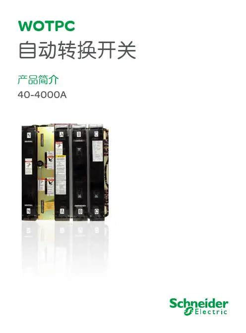

第七部分自动双电源转换系统选型表7-17-2A T S 系列自动电源转换系统选型表——M a s t e r p a c t MT/ -0530********E 32703I V E 模块A C P 底座B A / U A 控制器说明:1: 主回路断路器与备用回路断路器规格可以不同2: M a s t e r p a c t M T 不同型号和规格都可以组成自动电源转换系统3: 主备回路的断路器可以是抽屉式,也可以是固定式4: M C H 电操机构、X F /M X 线圈、I V E 模块、A C P 底座、B A /U A 控制器的额定电压必须相同5: 自动电源转换系统标准配置表如下:6: A T S 系统中的M T 断路器若要求通信功能, 要求使用E c o C o m 选件(无遥控功能)7: M a s t e r p a c t M T 可以使用机械联锁和电气联锁1 主电源回路断路器 备用电源回路断路器2 控制单元 控制单元3 M C H 电动操作机构 电动操作机构4 M X M X 5 X F 合闸线圈 X F 合闸线圈 6 P F 触点 P F 触点7 O F 触点 O F 触点8 C E 触点 (抽屉式) C E 触点 (抽屉式)9 电气联锁单元 I V E 模块10 A C P 底座11 自动控制器 (U A 或 B A )12 U A /B A 接线适配器注: B A 用于 2 U A 用于 1 路7-3两个断路器的电源自动切换系统可能的状态“常用” 0 1 0“备用”0 0 1QN: Masterpact 采用“常用”电源QR: Masterpact 采用“备用”电源IVE: 电气联锁和端子排M: 电动机构XF: 合闸线圈MX: 分励脱扣线圈CE: 接通位置的开关O F: 辅助切换开关SDE: 故障跳闸指示开关CH: “弹簧储能”开关PF: “合闸准备就绪”触点 (在断路器位于断开,未闭锁和操作机构储能时允许合闸)。

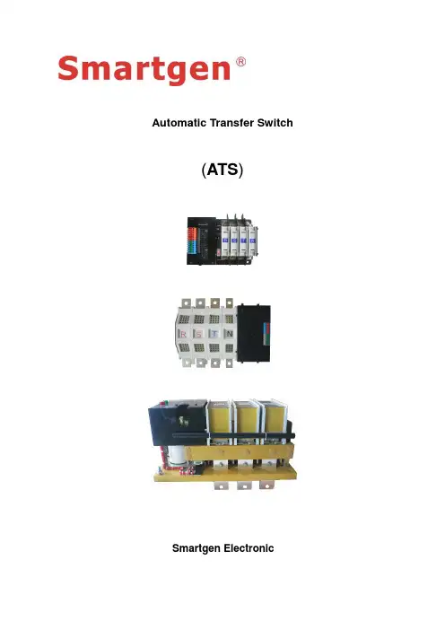
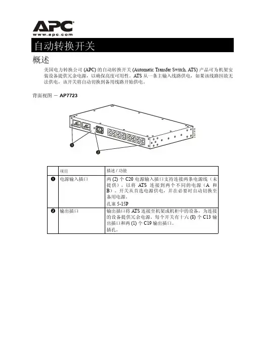
Automatic Transfer Switch(ATS)Smartgen ElectronicCONTENT1SUMMARY (4)2OPERATING CONDITIONS (4)3SPECIFICATION (4)4TYPE INSTRUCTION (4)5STRUCTURE (5)6CASE DIMENSIONS (5)6.1. T YPE “N” CASE DIMENSIONS AND TECHNICAL DATA (5)6.2. T YPE “T”C ASE DIMENSIONS AND TECHNICAL DATA (6)6.3. T YPE “M” EXTERNAL DIMENSIONS AND TECHNICAL DATA (8)7ATS CONNECTING DIAGRAM AND OPERATING PRINCIPAL (9)7.1. “N” AND “T” SIMPLE CONNECTING DIAGRAM (9)7.2. “M” SIMPLE CONNECTING DIAGRAM (10)8INSTALLATION AND TESTING (10)1 SUMMARYSmartgen SGQ Automatic Transfer Switch (ATS) is used in conditions from AC660V 50/60HZ to DC250V which under structure of electromagnetism driving. SGQ ATS can make fast loading transfer (transfer time ≤80ms) under two ways power supply. Also ATS can be widely used in Hi-buildings, post, telecommunications, mines, ships, medical, public health, military installations, and so on. Two ways power can be mains, gens and storage battery.5 STRUCTURESmartgen SGQ Automatic Transfer Switch (ATS) apply for structure of magnet coil driving and two ways interlocking of electric and mechanical. And ATS’s major contact structure is two-stable and one-moving, and the moving contact is “V” type design, in order to ensure there is no short circuit of the two-ways power supply. “N” and “T” apply for structure of single coils operation and the coil only have current while it is transferred, and this can extremely extend theYPE “N” CASE DIMENSIONS AND TECHNICAL DATARIGHT VIEWSpecification Case size Installation size Cupper bar(A) A2P A3P A4P D C B2P B3P B4P E M U TQ63N 172 200 228 186 155 139 167 195 165 5 12 27 Q125N 193 228 265 186 155 159 195 231 165 7 20 37“N” technical data6.3. T YPE “M” EXTERNAL DIMENSIONS AND TECHNICAL DATATOP VIEW RIGHT VIEW7 ATS CONNECTING DIAGRAM AND OPERATINGPRINCIPAL7.1. “N” AND “T” SIMPLE CONNECTING DIAGRAMNote:1. Position control I2. Position control II3. Aux. contact of position I4. Aux. contact of position IISB1 as No.1 power’s switch on button SB1 as No.2 power’s switch on button7.2. “M” SIMPLE CONNECTING DIAGRAMNote:1. Position control I2. Position control II3. Aux. contact of position I4. Aux. contact of position IISB1 as No.1 power’s switch on button SB1 as No.2 power’s switch on button 8 INSTALLATION AND TESTINGThe installation and testing of ATS must be operated by experts and people who much learn about switch equipments. Protection and preventive measures must be considered during the operation. The wires connection of switch major loop must make its down lead prohibit from any pressure and strong force. Should inspect if have any damage to switch or any harmful environment before installation or debugging. Meanwhile, should check the wires connection if loose during transportation. Also should make the switch is clean and clean way smudge, special prohibit any smudges on the surface ofinsulation parts. The smudges could be caused from the packing materials during transportation or in storage. When connect main loop, should make the two-ways power phase sequence as same. Also should strictly follow to wires diagram in manual when connect to second loop and pay attention to control the voltage grade of power. There must be have excellent ground-connection when installation. Considering the personal safety and quickness of switch transfer, the debugging handle for testing only and users never operate it with load. Should use handle to operate the switch first when debugging. If everything goes well, using manual button to power-driven operation. And ATS is normal running after there is no error.。
自动转换开关的毕业设计(机械CAD图纸)目录摘要 (1)Abstract (4)第一章绪论 (7)1.1 课题概况 (7)1.1.1当前双电源转换开关的现状 (8)1.1.2双电源转换开关的发展 (8)1.2课题研究涉及的有关概念 (11)第二章系统方案确定及控制原理 (13)2.1系统方案确定 (13)2.1.1自动转换开关的组成 (13)2.1.2系统方案的确定 (13)第三章控制系统设计 (18)3.1 SPT604电压传感器 (18)3.1.1 LM393电压比较器 (19)3.1.2 NE555施密特触发器 (21)3.1.3中间继电器 (22)3.1.4 ULN2003A达林顿晶体管 (23)3.1.5塑料外壳式低压断路器 (26)3.1.6跳线 (27)3.1.7控制原理图设计 (28)3.2报警电路设计 (28)第四章机械结构设计 (29)4.1机械结构设计要求 (29)4.2电机的选用 (30)4.2.1电机功率的确定 (30)4.2.2 电机类型的选择 (32)4.3系统机械传动路线 (33)4.4主轴的设计 (33)4.5六方离合销的设计 (39)第五章系统可靠性分析 (39)5.1电气控制部分可靠性分析 (40)5.2 机械传动部分可靠性分析 (41)5.3 总体注意事项 (42)第六章结论 (43)参考文献 (44)致谢 (46)自动转换开关的设计摘要研究本课题的目的及重要性:为保证重要负载供电的连续性,双电源自动转换开关的应用需求已越来越大,技术性能要求也越来越高。
转换一旦失败将会造成多种危害,电源间的短路或重要负荷断电,其后果都是严重的,这不仅仅会带来经济损失,也可能造成社会问题。
就其目前的发展现状来看,对双电源自动转换开关的研制和生产已是刻不容缓。
否则,就无法满足因人们生活质量的不断改善而对电源可靠性的要求越来越迫切,功能更完善的发展要求。
本文首先分别介绍了自动切换器的电气控制原理和机械系统的结构设计,并相应地给出了系统框图和控制系统硬件原理框图。
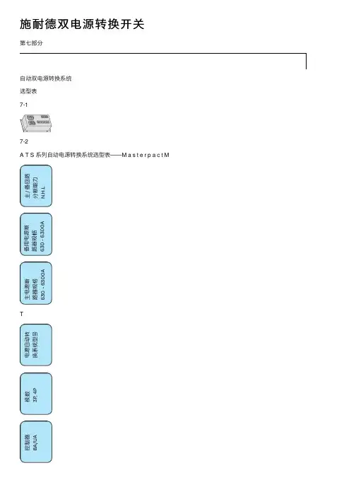
施耐德双电源转换开关第七部分⾃动双电源转换系统选型表7-17-2A T S 系列⾃动电源转换系统选型表——M a s t e r p a c t MT/ -0530********E 32703I V E 模块A C P 底座B A / U A 控制器说明:1: 主回路断路器与备⽤回路断路器规格可以不同2: M a s t e r p a c t M T 不同型号和规格都可以组成⾃动电源转换系统3:主备回路的断路器可以是抽屉式,也可以是固定式4: M C H 电操机构、X F /M X 线圈、I V E 模块、A C P 底座、B A /U A 控制器的额定电压必须相同5: ⾃动电源转换系统标准配置表如下:6: A T S 系统中的M T 断路器若要求通信功能, 要求使⽤E c o C o m 选件(⽆遥控功能)7: M a s t e r p a c t M T 可以使⽤机械联锁和电⽓联锁1 主电源回路断路器备⽤电源回路断路器2 控制单元控制单元3 M C H 电动操作机构电动操作机构4 M X M X 5 X F 合闸线圈 X F 合闸线圈 6 P F 触点 P F 触点7 O F 触点 O F 触点8 C E 触点 (抽屉式) C E 触点 (抽屉式)9 电⽓联锁单元 I V E 模块10 A C P 底座11 ⾃动控制器 (U A 或 B A )12 U A /B A 接线适配器注: B A ⽤于 2 U A ⽤于 1 路7-3两个断路器的电源⾃动切换系统可能的状态“常⽤” 0 1 0“备⽤”0 0 1QN: Masterpact 采⽤“常⽤”电源QR: Masterpact 采⽤“备⽤”电源IVE: 电⽓联锁和端⼦排M: 电动机构XF: 合闸线圈MX: 分励脱扣线圈CE: 接通位置的开关O F: 辅助切换开关SDE: 故障跳闸指⽰开关CH: “弹簧储能”开关PF: “合闸准备就绪”触点 (在断路器位于断开,未闭锁和操作机构储能时允许合闸)。
施耐德万高技术支持技术支持Q&A技术支持1.1 综述1. 双电源自动转换系统中CB级和PC级分别是什么意思?施耐德是哪一类的产品?在双电源转换系统中,PC级是指能够接通、承载、但不用于分断短路电流的双电源转换系统(无过电流保护);CB级是指配备过电流脱扣器双电源转换系统,它的主触头能够接通并用于分断短路电流(即具备短路过载保护功能)。
施耐德电源转换开关产品中既有CB级(WATSN、ATNSX、ATMT、WSATS)的产品,也有PC级(WOTPC、WBTPC、WTS、WATSG、WATSN、WSATS)产品。
2. 自动转换开关电器常用使用类别怎样选用?使用类别:ATSE(自动转换开关电器)常选用AC-33A、AC-33B、AC-33 iA、AC-33iB作为其使用类别。
AC-33 iA、AC-33iB含义是:系统总负荷包含笼型电动机及阻性负载。
AC-33A、AC-33B含义是:电动机负载或包含电动机、电阻负载和30%以下白炽灯负载的混合负载。
其中A表示频繁操作,B表示不频繁操作。
3. 建筑消防电气设计上有没有对电源切换的要求, 如果有应设置在什么位置?火灾自动报警、消防通信等消防用电设备均设有应急电源。
当使用的电源故障停电时,被停止供电的重要负荷采用电源自动切换装置(ATS)切换至另一电源。
《高层民用建筑设计防火规范》第9.1.2条规定:“高层建筑的消防控制室、消防水泵、消防电梯、防烟排烟风机等的供电,应在最末一级配电箱处设置自动切换装置。
4. 首端与末端设置转换开关的不同点?ATS设在首端 (如在变电所低压的第一级配电处)和设在末端相比,末端设ATS时,除了电源故障停电能自动切换外,当配电设备故障或低压线路上发生故障而停电时,末端ATS也能动作,增加了负荷的供电可靠性;首端设ATS时,如果配电设备或低压线路发生故障而停电,该ATS不动作,这样就无法保证负荷的继续供电,所以末端ATS比首端ATS更为可靠。
MATSAutomatic transfer switches Intelligent design High reliabilityMATS Automatic Transfer SwitchContentsAutomatic transfer switchesProduct description Design graphical and operation theory Product guide Technical parameter Controller description State indication Delay setup Second terminal wiring description Controller technical data Demission (234671*********)Product type●CB class ;●PC class 。
MATS automatic transfer switchesMATS series automatic transfer switches is based on Eaton's MCCB MCB and disconnect switches. Mechanical andelectrical interlocking are build-in and make two source no paralleling. Three types of controllers can adapt complex applications.●Model intelligent and compact design;●Low noise and safe transfer with the engine drive mechanism;●Low consumption in running time;●Mechanical and electricalinterlocking make no paralleling in transfer process;●Undervoltage 、lack phase 、 Loss voltage sensor;automatic pick up;●CB class is based on breaker which has line protectionfunction; PC class is based on disconnect switch; ●Auto / Man;●Online time set;●Fire interlocking and LED indicating are standard;●Can not transfer when the emergency is error;●Condition indication.Product descriptionMATS automatic transfer switches2M ats Automatic Transfer Switches /electrical ContentsDescription PageMATS Automatic Transfer SwitchDesign graphical and operation theoryStandardGB 14048.11-2002《Low voltageswitches and automatic transferswitches》Operating environment● Temperature: -25℃~700C● Altitude: <2000m● Humidity: <95%● Pollution: 3● IP20Design graphicalOperation theory● The automatic transfer switchis made of controller and acouple of switches that makethe transfer between normaland emergency;● Auto and Manual model can beprogrammable on thefaceplate;● Normal and emergency sensorwhen choose the auto model.The power source will transfer to emergency when normal iserror and emergency is right;● When normal is ready, thepower source will transfer tonormal achieve pick upfunction. When choosemanual, the controller will turn off, use the handle to transferthe power source. This modelis used to repairing andabnormal states;● MATS Automatic TransferSwitch is build-infire-interlocking function. Whenfire-interlocking signal iseffective, the controller willopen both normal andemergency to cut the powersource. After single has beenremoved, you must re-plug itand reset the controller;● Normal and emergency stateindication;● MATSB is used for Utility-Generator application.3Mats Automatic Transfer Switches /electricalCB class PC class4MATS Automatic Transfer SwitchProduct guideMats Automatic Transfer Switches /electrical CB class product guideMCB based●Breaker: PL9, 6kA;●Trip curve: C type or D type;●Amperes: 0.5, 1, 2, 3, 4, 6, 10, 13, 16, 20, 25, 32, 40, 50, 63A;●Controller: A type only.NoteMCCB based●Controller: A, B, C;●Break: LZM;●Inm: 1: 160A, 2: 250A, 3: 630A;●Break capability: C-36kA, N-50kA, S-70kA;●Protective unite: A: Thermomagnetic trip;AE: Electronic tripping device;●Amperes: 1: 20, 25, 32, 40, 50, 63, 80, 100, 125, 160A ;2: 160, 200, 250A ;3: 320, 400, 500, 630A 。
Easy-to-operate ATS controller with advanced diagnostic capabilitiesThe Eaton ATC-900 controller brings ease of use, adaptability, supervisory and programming capabilities to automatic transfer switch (ATS) equipment. Extreme reliability makes this controller ideal for mission-critical applications in healthcare, wastewater, data center and other industrial and commercial applications. The ATC-900 controller is compatible with Eaton’s complete transfer switch product offering including contactor, molded case and power frame type transfer switches.Ease of use• Color display for systemstatus, metering data,programming, diagnostics,help and troubleshooting• Simple arrow keys are usedfor quick screen navigation• LED mimic bus withsource available and sourceconnected indication• Easy-to-interpret functiondescriptions without use codes• Data screens are groupedfor ease of viewing andsecure edits• Engine test, help, lamptest, enter and bypass timerpushbuttons• PC-based setpoint editor tool(EASE)—create, edit and savesetpoint configuration files• USB port for upload/downloadof metering data, eventdetails, setpoint configurationfiles and firmware updatesAdvanced diagnostics• Time/date stamped eventsummaries and detailsincluding historicalmetering values• High-speed event waveformcapture of voltage, frequencyand current• Export event log (csv file) withmetering data to USB drive forpost-event analysis• Integral load-side meteringmodule (optional) providesreal-time display of power,electrical current andpower factorMonitoring and control• Selective kilowatt load shed(optional module)• Remote load testing• Primary and secondarycontrol functionality for three-source applications such asutility-generator-generator• Industry standardcommunication—serial(RS-485/Modbus T RTU) andEthernet (optional module)• Remote management of asingle or multiple ATC-900with HMi Remote AnnunciatorControllerFlexibility• Open (time delay, in-phasemonitor) or closed transitioncontrol• For use in low-voltage (up to600 Vac) and medium-voltagesystems (up to 46 kVac)• Up to 20 field-programmablecontrol inputs and relayoutputsSmart functionality• ATS Health reports equipmentendurance, electricalexcursions, performance andcomponent health, allowingservice personnel to makeinformed maintenancedecisions and manage risk• Maintenance Watch E issuesautomated notifications andtask guidance to performscheduled inspection andmaintenance based onNFPA T 110—standard foremergency and standbypower systemsEaton is a registered trademark.All other trademarks are property of their respective owners.Eaton1000 Eaton Boulevard Cleveland, OH 44122United States © 2023 EatonAll Rights Reserved Printed in USAPublication No. PA140003EN / Z27509April 2023Features Description System applicationThree-phase or single-phase Low-voltage: up to 600 VacMedium-voltage: up to 46 kVac (external PT required)Features DescriptionOutputs (fixed)Source 1 available and Source 2 available (Form C, rated 10 A at 250 Vac/30 Vdc) Generator start 1 and Generator start 2 Follow us on social media to get the latest product and support information.。