Kent Introl 调节阀说明书
- 格式:doc
- 大小:1.04 MB
- 文档页数:7
调节阀手册第一章概述O.P.小洛维特在现代化工厂的自动控制中,调节阀起着十分重要的作用,这些工厂的生产取决于流动着的液体和气体的正确分配和控制。
这些控制无论是能量的交换、压力的降低或者是简单的容器加料,都需要靠某些最终控制元件去完成。
最终控制元件可以认为是自动控制的“体力”。
在调节器的低能量级和执行流动流体控制所需的高能级功能之间,最终控制元件完成了必要的功率放大作用。
调节阀是最终控制元件的最广泛使用的型式。
其他的最终控制元件包括计量泵、调节挡板和百叶窗式挡板(一种蝶阀的变型)、可变斜度的风扇叶片、电流调节装置以及不同于阀门的电动机定位装置。
尽管调节阀得到广泛的使用,调节系统中的其它单元大概都没有像它那样少的维护工作量。
在许多系统中,调节阀经受的工作条件如温度、压力、腐蚀和污染都要比其它部件更为严重,然而,当它控制工艺流体的流动时,它必须令人满意地运行及最少的维修量。
调节阀在管道中起可变阻力的作用。
它改变工艺流体的紊流度或者在层流情况下提供一个压力降,压力降是由改变阀门阻力或"摩擦"所引起的。
这一压力降低过程通常称为“节流”。
对于气体,它接近于等温绝热状态,偏差取决于气体的非理想程度(焦耳一汤姆逊效应)。
在液体的情况下,压力则为紊流或粘滞摩擦所消耗,这两种情况都把压力转化为热能,导致温度略为升高。
常见的控制回路包括三个主要部分,第一部分是敏感元件,它通常是一个变送器。
它是一个能够用来测量被调工艺参数的装置,这类参数如压力、液位或温度。
变送器的输出被送到调节仪表一一调节器,它确定并测量给定值或期望值与工艺参数的实际值之间的偏差,一个接一个地把校正信号送出给最终控制元件一一调节阀。
阀门改奕了流体的流量,使工艺参数达到了期望值。
在气动调节系统中,调节器输出的气动信号可以直接驱动弹簧-薄膜式执行机构或者活塞式执行机构,使阀门动作、在这种情况下,确定阀位所需的能量是由压缩空气提供的,压缩空气应当在室外的设备中加以干燥,以防止冻结,并应净化和过滤。
肯特阀门说明书一、产品概述肯特阀门是一种常见的工业阀门,主要用于控制介质的流量和压力。
它由阀体、阀瓣、阀杆、密封圈等部件组成,具有结构简单、操作方便、密封可靠等特点。
二、产品特点1. 结构简单:肯特阀门采用直通式结构,流道畅通,流体阻力小。
2. 操作方便:肯特阀门采用手动操作方式,旋转角度大,开关灵活。
3. 密封可靠:肯特阀门采用双向密封设计,密封性能好,不易泄漏。
4. 耐腐蚀:肯特阀门主要材料为不锈钢和铜合金等耐腐蚀材料。
三、使用方法1. 安装:在安装前应检查肯特阀门的外观是否完好无损,并清洗内部杂质。
根据管道布局和介质流向确定安装位置,并确保与管道连接牢固。
2. 操作:手动旋转肯特阀门的手柄即可实现开关操作。
注意不要过度旋转或用力过猛,以免损坏零部件。
3. 维护:定期检查肯特阀门的密封性能和操作情况,如发现问题及时维修或更换零部件。
四、注意事项1. 在使用肯特阀门时,应根据介质的性质和流量选择合适的规格和型号。
2. 在操作肯特阀门时,应注意力度适当,不要过度旋转或用力过猛。
3. 在长期未使用肯特阀门时,应定期进行维护保养,以确保其正常运行。
五、常见故障及处理方法1. 泄漏:可能是密封圈老化或损坏导致的。
此时需要更换密封圈。
2. 卡死:可能是阀杆损坏或堵塞导致的。
此时需要清洗或更换阀杆。
3. 无法开关:可能是手柄松动或零部件损坏导致的。
此时需要紧固手柄或更换零部件。
六、结语以上就是肯特阀门的详细说明书,希望对大家有所帮助。
在使用肯特阀门时,请务必严格按照说明书操作,并注意安全事项。
如有任何疑问,请咨询专业人士。
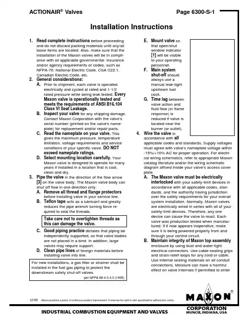
mInstallation InstructionsE.Mount valve sothat open/shut window indicator [1] will be visible to your operating personnel.F.Main systemshut-off should always use a manual leak-tight upstream fuel cock.G.Time lag betweenvalve action and fluid flow (or flame response) isreduced if valve is located near the burner (or outlet).4.Wire the valve inaccordance with allapplicable codes and standards. Supply voltages must agree with valve’s nameplate voltage within -15%/+10% AC for proper operation. For electri-cal wiring schematics, refer to appropriate Maxon catalog literature and/or the wiring schematic diagram affixed inside your valve’s access cover plate.A.The Maxon valve must be electricallyinterlocked with your safety-limit devices in accordance with all applicable codes, stan-dards, and the authority having jurisdiction over the safety requirements for your overall system installation. Normally, Maxon valves are electrically wired in series with all of your safety-limit devices. Therefore, any one device can cause the valve to react. Each valve was production tested when manufac-tured. If it now appears inoperative, make sure it is being powered properly from and through your control circuit.B.Maintain integrity of Maxon top assemblyenclosure by using dust and water-tightelectrical connectors. Use cable-sealing grips and strain-relief loops for any cord or e internal sealing materials on all conduit connections. Moisture can have a harmful effect on valve internals if permitted to enter1.Read complete instructions before proceedingand do not discard packing materials until any/all loose items are located. Also, make sure that the installation of the Maxon valves will be in compli-ance with all applicable governmental, insurance and/or agency requirements or codes, such as NFPA-70, National Electric Code, CSA C22.1,Canadian Electric Code, etc.2.General considerations:A.Prior to shipment, each valve is operatedelectrically and cycled at rated and 1-1/2rated pressure while being leak tested. Every Maxon valve is operationally tested and meets the requirements of ANSI B16.104Class VI Seat Leakage.B.Inspect your valve for any shipping damage.Contact Maxon Corporation with the valve’s serial number (printed on the valve's name-plate) for replacement and/or repair parts.C.Read the nameplate on your valve. Thisgives the maximum pressure, temperature limitation, voltage requirements and service conditions of your specific valve. DO NOT exceed nameplate ratings.D.Select mounting location carefully. YourMaxon valve is designed to operate for many years if installed in a location that is cool,clean and dry.3.Pipe the valve in the direction of the flow arrow[3] on the valve body. The Maxon valve body can shut off flow in one direction only.A.Remove all thread and flange protectorsbefore installing valve in your service line.B.Teflon tape acts as a lubricant and greatlyreduces the pipe wrench turning force re-quired to seal the threads.Take care not to overtighten threads as this can damage the valve.C.Good piping practice dictates that piping beindependently supported, so that valve bodies are not placed in a bind. In addition, large valves may require support.D.Clean pipe lines of foreign materials beforeinstalling valve into line.For new installations, a gas filter or strainer shall be installed in the fuel gas piping to protect the downstream safety shut-off valves.per NFPA 86-4-2.4.3 (1995)Installation Instructions (cont'd.)through wiring connectors. Make sure that allaccess cover plates are in place and securelyfastened. All cover screws should be tight-ened using an alternate cross corner tighten-ing pattern to the values shown below.While all covers are torqued at time of pro-duction testing, torque should be recheckedperiodically to ensure adequate sealingprotection.5.Pre-operational exercising:Prior to initial fluid flow start-up and with upstream manual cock still closed, operate the valveelectrically for 10-15 cycles. This not only pro-vides an electrical check, but also wipes valvebody disc and seat free of accumulated foreignmatter.6.Air actuated valves require clean, dry air atdesignated pressures. Outlets and vents, wherepresent, should be protected from accidentalblockage.NOTE: Although Maxon ACTIONAIR® Valves donot require lubrication, they do contain Buna Nbellows diaphragms in the air actuator sub-assembly. Quality of the compressed air supplymust not contain any lubricant that is not compat-ible to Buna N elastomers. Although manysynthetic oils and additives have been publicizedfor advanced lubricating characteristics in pneu-matic systems, strict attention should be exer-cised to avoid their use, even in small amounts. 7.Air-operated ACTIONAIR® Valves equipped withthe Power-to-Close or Power-to-Open actuatorassembly require electrical power and com-pressed air to be actuated. The valve will remainin the actuated position for a minimum of 15minutes on loss of power. The valve will return to its normal position with a loss of cylinder air orcontinuous power to the overriding solenoid valve.r evoC)sb l-n i(euq roTs r evocssecca2-"52.05mInstallation Instructions (cont'd.)Top Assembly RotationMaxon valves can and should be ordered in aconfiguration compatible with planned piping, but ifopen/shut indicator window is not visible and/or valveorientation is not proper, the top assembly can berotated in 90° increments around the valve bodycenterline axis by the following procedure:1.Shut off all electrical and pneumatic powerand close off upstream manual cock.2.Remove wiring access cover plate [2] anddisconnect power lead wires. (Tag carefully forlater re-assembly.)3.Remove conduit, electrical leads, and any airline connections.4.Note physical position of any signal switchactuator wands on auxiliary signal switches (seeswitch arrangement sketch).5.Unscrew the two body bolts [4] screwed up fromthe bottom to 1/4 inch. DO NOT completelyremove. These bolts secure the valve body [3] tothe valve’s top assembly housing [5].6.Gently lift the top assembly [5] (not more than1/4" in height); just enough to break the sealbetween the valve body assembly and the rubbergasket adhering to the bottom of the top housing.This step may require loosening the stemcoupling [6] to permit components freedom ofmovement.WARNING: LIFTING TOO FAR MAY DISLODGESOME SMALL PARTS INSIDE THE TOPHOUSING, REQUIRING COMPLEX RE-ASSEMBLY AND RETESTING BY TRAINEDFACTORY PERSONNEL.7.Remove the two body bolts [4] screwed up fromthe bottom (were partially unscrewed in step 5).8.Carefully rotate top assembly to the desiredposition in a plane parallel to the top of the valvebody casting. Rotate the top housing about 30°beyond this position, and then rotate it back.Reposition the top housing back down onto thevalve body casting. This should align the open/shut indicator with its window and provide proper alignment of the internal mechanism.9.Realign holes in valve body casting with thecorresponding tapped holes in the bottom of the top assembly housing. Be sure the gasket is still in place between the body and top housing.Retighten the stem couplings.Wiring Diagram Auxiliary Switch ArrangementA–Number Coded Wires H–Mounting ScrewsB–Rubber Grommet I –Spring Retainer Extension C–Mounting Screws J–Switch WandD–Normal (de-energized)K–Actual (energized) Position Switch Position SwitchE–Insulating Barrier L–Switch WandF–Bracket Mounting Pad M–Switch Mounting Bracket G–Drive Pin & Locating Hole N–GasketmmInstallation Instructions (cont'd.)Top Assembly Rotation (cont'd.)10.Reinsert the body bolts up from the bottomthrough the body and carefully engage threads of the top assembly. Tighten securely.11.Reconnect conduit, electrical leads, and allpneumatic lines, then check that signal switch wands are properly positioned and that open/shut indicator moves freely. Failure to correct any such misalignment can result in extensive damage to the internal mechanism of your valve.12.Energize valve and cycle several times fromclosed to full open position. Also electrically trip the valve in a partially opened position to prove valve operates properly.13.Replace and secure side cover access plateand place valve in service.Alternate Top Assembly Positionsre v o C )s b l -n i (e u q r o T sr e v o c s s e c c a 02-"52.05“R ”“TO ”“AW ”“L ”Maxon MaxonFour top assembly positions are available for most Maxon valves. When looking at the open/shut window indicator of a valve assembly, the motor (for motorized version), or the operating handle (for manual version), will be on the left side of the top assembly. The valve body is on the bottom. From thisview, the unidirectional valve body and the arrow on the valve body casting points in direction of fluid flow:to the right (position "R"), to the left (position "L"),towards you (position "TO") or away from you (posi-tion "AW"). With smaller size swinging gate valve bodies, only position "R" and position "TO" may be used.mOperating InstructionsAll manual reset valves may be operated manu-ally when solenoid is electrically energized, but electrical tripping is recommended for normal shut-downs.Manual reset valves require two positive actions to open: a half rotation of handle to latch internal mechanism, and a reversed half rotation of handle to open valve. This refers to normally closed valves.With normally open valves, the procedure is the same, but the valve body position (i.e., open or closed) is opposite to the normally closed version.Normally closed motorized valves begin open-ing cycle immediately upon being powered; motor runs only until full open position is reached. Normally open valves begin to close immediately, and motor runs until fully closed position is reached.Refer to appropriate catalog bulletin and specifi-cation page for operating sequence applying to your specific valve. Never operate valve until all essen-tial allied equipment is operative and any neces-sary purges completed. Failure of pneumatically operated valve to operate normally indicates that it is not powered. Check this first! Then check air control solenoid and/or cylinder air supply.Main system shut-off should always be accom-plished with an upstream leak-tight manual fuel cock.All Maxon valves react within a fraction of asecond when de-energized. One cycle drop in electri-cally supplied power can cause this reaction.Operator should be aware of and observe characteristic opening/closing action of the valve. Should operationever become sluggish, remove valve from service and contact Maxon for recommendations.Address inquiries to: Maxon Corporation, Muncie, IN 47302, Phone (765) 284-3304FAX (765) 286-8394Always include valve serial number and nameplate information to insure positive identification.Maintenance InstructionsMaxon valves are endurance tested far in excess of the most stringent requirements of the various ap-proval agencies. They are designed for long life even if frequently cycled, and to be as maintenance-free and trouble-free as possible.Every Maxon valve is operationally tested and meets the requirements of ANSI B16.104 Class VI Seat Leakage when it leaves our plant.Top assembly components require no field lubrication and should never be oiled.Auxiliary switches, motors and solenoids, may be replaced in the field.WARNING: Do not attempt field repair of valve body, top assembly or motor drive unit. Any alterations void all warranties.Valve leak test, performed with valve in line as prescribed by jurisdictional authorities, is strongly encouraged and should be done on a regularly scheduled basis. In rare instances where valve shows leakage, perform Pre-Operational Exercising (see Installation Instructions) and retest. If leakage does not stop, remove valve from service.Maxon valves are designed to be used with clean fluids. If foreign material is present in the fuel line, it will be necessary to inspect thevalve to make certain it is operating properly. If abnormal opening or closing is observed, the valve should be removed from service. Contact your Maxon representative for instructions.Insurance authorities agree . . .. . . that the safety of any industrial fuel burning installation is dependent upon well-trained operators who are able to follow instructions and to react properly in cases of emergency. Their knowledge of, and training on, the specific installation are both vital to safe operation.Safety controls may get out of order without the operator becoming aware of it unless shutdowns result. Production-minded operators have been known to bypass faulty controls without reporting the trouble.Continued safe operation of any installation is then assured only if the plant management carefully develops an exact schedule for regular periodic inspection of all safety controls, insisting that it then be rigidly adhered to.A main gas shut-off cock should be located upstream from all other fuel train piping compo-nents and used to shut off all flow of fuel for servicing and other shutdowns.All safety devices should be tested at least monthly* and more often if deemed advisable. Periodic testing for tightness of manual or motor-ized shut-off valve closure is equally essential.*per NFPA 86-Appendix B-4 (1995)Operator should be aware of and observe characteristic opening/closing action of the valve. Should operation ever become sluggish, remove valve from service and contact Maxon for recommendations.Address inquiries to: Maxon Corporation, Muncie, IN 47302, Phone (765) 284-3304FAX (765) 286-8394Always include valve serial number and nameplate information to insure positive identification.mmElectrical DataACTIONAIR ® ValvesNormally Closed ValvesNormally closed Series 1000 & 3000ACTIONAIR ® Valves(internal wiring schematic)Power-to-Close Series 1000 & 3000ACTIONAIR ® Valves(internal wiring schematic)WARNING: ACTIONAIR ®Valves equipped with Power-to-Close actuator assembly require electrical power and compressed air to be opened. The valve will remain in the openedposition for a minimum of 15 minutes on loss ofpower. The valve will return to its normally closed position with a loss of cylinder air or continuous power to the overriding solenoid valve.mElectrical DataACTIONAIR ® ValvesNormally Open ValvesNormally open Series 2000ACTIONAIR ® Valves(internal wiring schematic)Power-to-Open Series 2000ACTIONAIR ® Valves(internal wiring schematic)WARNING: ACTIONAIR ®Valves equipped with Power-to-Open actuator assembly require electrical power and compressed air to be closed. The valve will remain in the closedposition for a minimum of 15 minutes on loss ofpower. The valve will return to its normally open position with a loss of cylinder air or continuous power to the overriding solenoid valve.Notes m。
TECH-SEAL INTERNATIONAL3131 West Little York Rd Houston, Texas 77091Phone: 713-691-0668Fax: 713-358-9330Adjustable Choke Operation and Maintenance ManualRevision: 0Date: 6/06/2013Approved By: J.ATABLE OF CONTENTS1.Introduction ……………………………………………………………………….page 32.Choke Specifications & Features………………………………………………….page 43.Choke Operation…………………………………………………………..………page 54.Exploded View…………………………………………………………………….page 65.Maintenance……………………………………………………………………….page 106.Contact information……………………………………………………………….page 18INTRODUCTION:The 2” Adjustable Chokes is field-proven design which have been manufactured by Tech-Seal International from the high quality material. Tech-Seal Chokes conform to current API requirements, both functionally and in term of calculated stresses. Adjustable Choke is used to control flow rate; it is an important part of a manifold controlling downstream pressure and flow rates during flow-back process.2” 1502 ADJUSTABLE CHOKE SPECIFICATION & FEATURES:Specifications:∙2” 1502 Female Inlet x 2” 1502 Male Outlet∙10,000 psig CWP/ 15,000 psig CWP∙¾” max Orifice and 1.00” max Orifice∙¾” FL/TC and 1.00” FL/TC Seats∙Solid carbide TipFeatures:∙Low Maintenance∙Easy to read position indicator∙Thumb Screw for locking steam∙Available as 2 types: Adjustable Choke and Positive Choke∙Forged steel bodies∙Available H2S service (NACE MR-01-75)∙Choice of orifice sizes∙Easy to convert orifice sizes in fieldCHOKE OPERATION:The 2” 1502 Adjustable Choke features the needle and seat design to allow controllingpressures and flow rate. The choke is operated by turning the hand wheel in CW or CCW in order to obtain a specified downstream pressure, or a desired flow rate.When the desired flow rate or specified pressured is achieved, the thumb screw will beused to locked the stem in fixed position.The choke comes with a position indicator. It is used to determine the bean size needed for the positive choke. Every number on the position indicator represents the equivalent orifice diameter in 1/64th of an inch.NOTE:THIS ADJUSTABLE CHOKE IS NOT DESIGNED TO PROVIDE A POSITIVE SEAL.THEREFORE, AN ISOLATION VALVE SHOULD BE USED IN CONJUNTION WITH THE CHOKE.EXPLODED VIEWS & PART LISTTHE THREE MAIN ASSEMBLIES OF THE CHOKE:Bonnet AssemblyChoke Tee BodyChoke Saver Assembly2” 1502 POSITIVE CHOKE∙EXPLODED VIEW:1 Wing Nut 4 Union Seal 2” 1502 7 Choke saver2 Retainer Ring 5 Body3 Blanking Cap 6 Split Ring∙REPLACEMENT PART & PART NUMBER2” 1502 ADJUSTABLE CHOKE EXPLODED VIEW:REPLACEMENT PART & PART NUMBER`MAINTENANCEWARNING:Tech-Seal Int’l cannot anticipate all of situations a user may encounter while installing, using or repairing products. Therefore, the user must know and follow all applicable industry specifications on the safe installation and use.Failure to follow these warning and instructions could result in serious injury or death!Disassembly:NOTE: Protecting all the sealing surfaces all the time during disassembly or installation process1.Secure the choke assembly on a stationary safe surface.2.Bleed off any internal pressure from the choke assembly3.Loosen the thumb screw and back up the stem away from the seat by turning thehandle CCW.4.Loosen the hammer nut and remove the bonnet assembly.5. Using a choke wrench to remove the seat from the choke tee body6.Remove thumb screw (10), hex nut (1), indicator (4), washer and hand wheel fromthe stem.7.Remove the wing nut(3) from the bonnet assembly8.Unscrew and remove the stem(15) from the bonnet assembly9.Unscrew two socket cap screws and remove the bonnet cap.ing an adjustable wrench to remove the drive bushing (6).11. Remove the snap ring (14) from the bonnet seal pocket.12.Remove stem guide (13), packing retainer (12) and packing set (11) from the sealpocket.13.Unscrew the wing nut to remove the choke saver (21) from the choke tee body(18).INSPECTION-Clean all components-Visual inspection for corrosion, erosion, or any sign of fatigue crack.-Check the shoulder radius of the male end connection for any sign of fatigue crack or corrosion damage.-Check minimum wall at the end connections (see the next page)-Inspect stem carbide tip, and replace as necessary.-Inspect stem sealing surface, and replace as necessary-Inspect stem external thread, and replace as necessary-Inspect seal pocket surface of the bonnet housing for any sign of wear and damage-Check the external thread and carbide surface of the seat for any sign of damage.NOTE:Tech-Seal Int’l highly recommended any dimensions found to be at or thinner the minimum wall thickness requirements, the part or component must be repaired or replaced. Do not use worn, eroded, corrode products.21TSI Flow Products, Inc. Corporate Office CLEBURNE, TX5656 Wheatley St.1717 Hines Rd. Houston, TX 77091 Cleburne, TX 76031 Phone: (713) 691‐0668 Toll Free: 888.593.9143 Fax: (713) 691‐2328 Phone: 817.773.2536Hours: Monday ‐Friday, 8AM ‐5PM CST. Fax: 817.506.7697 CORPUS CHRISTI, TX BRIDGEVILLE, PA 4517 Baldwin 580 Mayer St.Corpus Christi, TX 78408 Bridgeville, Pa. 15017 Toll Free: 877.886.0202 Phone 412‐257‐0100 Phone: 361.882.0202 Fax: 412‐980‐3722Fax: 361.882.0205 .rchurilla@tsi ‐ KILGORE, TXTOWANDA, PA 302 S. longview St. Rr#6 box 6019‐9 Kilgore, TX 75662 Reeves business park Toll Free: 877.984.2870 Towanda pa 18848 Phone: 903.984.2870 570 297 2300Fax: 903.983.3750bpond@tsi ‐。
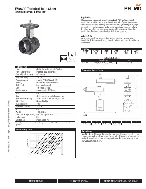
Close-off pressures are variable and actuator dependent, consult Select Pro and/or Price Guide for specifics.ApplicationThese valves are designed to meet the needs of HVAC and commercial applications requiring bubble tight shut-off for liquids. Typical applications include chiller isolation, cooling tower isolation, change-over systems, large air handler coil control, bypass and process control applications. The large Cv values provide for an economical control valve solution for larger flow applications. Designed for use in Victaulic® piping systems.Jobsite NoteValve assembly should be stored in a weather protected area prior toinstallation. Reference the butterfly valve installation instruction for additional information.2*AFAB C DEF17.0” [433]3.8” [97]16.4” [416]14.3” [363]2.0” [51]Safety NotesWARNING: For Belimo products sold in California: these products do or may contain chemicals which are known to the State of California to cause cancer and or birth defects or other reproductive harms. For more information see .F665VIC Technical Data SheetPressure Enhanced Rubber SeatD a t e c r e a t e d , 09/11/2019 - S u b j e c t t o c h a n g e . © B e l i m o A i r c o n t r o l s (U S A ), I n c .AFAB C DEF10.5” [267]3.8” [97]12.3” [312]10.2” [260]2.0” [51]GRAB C D EF10.8” [275]3.8” [97]10.2” [260]8.1” [206]2.0” [51]Dimensions (Inches [mm])AMA B C DEF9.8” [249]3.8” [97]12.3” [312]10.2” [260]2.0” [51]Dimensions (Inches [mm])GR N4AB C DEF14.1” [358]3.8” [97]13.6” [345]11.5” [292]2.0” [51]F665VIC Technical Data SheetPressure Enhanced Rubber SeatD a t e c r e a t e d , 09/11/2019 - S u b j e c t t o c h a n g e . © B e l i m o A i r c o n t r o l s (U S A ), I n c .GMA B C DEF9.9” [251]3.8” [97]12.3” [312]10.2” [260]2.0” [51]F665VIC Technical Data SheetPressure Enhanced Rubber SeatD a t e c r e a t e d , 09/11/2019 - S u b j e c t t o c h a n g e . © B e l i m o A i r c o n t r o l s (U S A ), I n c .†Rated Impulse Voltage 4kV, Type of Action 1.AA.B, Control Pollution Degree 3.Safety NotesWARNING: For Belimo products sold in California: these products do or may contain chemicals which are known to the State of California to cause cancer and or birth defects or other reproductive harms. For more information see .AFBUP-S-X1 Technical Data SheetOn/Off, Spring Return, AC/DC 24 VD a t e c r e a t e d , 09/11/2019 - S u b j e c t t o c h a n g e . © B e l i m o A i r c o n t r o l s (U S A ), I n c .Wiring Diagrams!WARNING! LIVE ELECTRICAL COMPONENTS!During installation, testing, servicing and troubleshooting of this product, it may be necessary to work with live electrical components. Have a qualified licensed electrician or other individual who has been properly trained in handling live electrical components perform these tasks. Failure to follow all electrical safety precautions when exposed tolive electrical components could result in death or serious injury.Meets cULus requirements without the need of an electrical ground connection.AActuators with appliance cables are numbered.UP Universal Power Supply (UP) models can be supplied with 24 VAC up to240 VAC, or 24 VDC up to 125 VDC.Apply only AC line voltage or only UL-Class 2 voltage to the terminals of auxiliary switches. Mixed or combined operation of line voltage/safetyextra low voltage is not allowed.Provide overload protection and disconnect as required.Actuators may also be powered by 24 VDC.Two built-in auxiliary switches (2x SPDT), for end position indication, interlock control, fan startup, etc.45Actuators may be powered in parallel. Power consumption must be observed.48Parallel wiring required for piggy-back applications.AFBUP-S-X1 Technical Data SheetOn/Off, Spring Return, AC/DC 24 VD a t e c r e a t e d , 09/11/2019 - S u b j e c t t o c h a n g e . © B e l i m o A i r c o n t r o l s (U S A ), I n c .。

Parker Solenoid Valves with Manual OverrideFor equipment test and power outageMarkets• Industrial equipment process• Energy (solar power)• Agriculture• Transportation Applications• Instrumentation equipment• Analyzers and diagnostic equipment • Process control• Lubrication equipment• Pilot valve actuation• Mobile fuel shut off• Textile and dry cleaning equipment • Irrigation systems Benefits• Locking manual override• Compact design• Compatible with all coils in valve family • Brass or Stainless with NBR seals • 2" NPT valves have a slow close feature to prevent water hammer Technical Data• 2-way and 3-way configurations • Flow factors up to 38.6• Operating Pressure up to 230 psi • Available in 1/4" to 2" NPT brass or 1/4" NPT stainless steelProductParker's locking manual override option for 2-way and 3-way stainless steel and brass solenoid valves provide more application solutions. Solenoid valves are designed to start and stop the flow of media when directed by an electrical signal. When electricity is not available to shift the valve into the ‘on’ position, a mechanical method must be used. These valves have this option. Instances where non-electrical valve function may be required include checking a system during start up, trouble shooting a problem or operation in a power failure.For industrial processes where manual override is required, Parker solenoid valves with manual override are the ideal solution.Parker’s Fluid Control Division has always offered 4-way pneumatic valves for valve actuation with manual override. Now, manual override is an option in the multi-mediasolenoid valves as well.CAT MANOVR0915 Dec. 2015© 2015 Parker Hannifin Corporation. All rights reserved.Valve Assembly Part NumbersOrderingFor simplicity, valves are shown with 1/2" conduit enclosures and 120/60 or 24 VDC coils. For other voltages or DIN coils, please contact the factory.Questions regarding this information can be directed to Technical Support at 1-860-827-2300.Parker Hannifin Corporation Fluid Control Division 95 Edgewood Avenue New Britain, CT 06051phone 860 827 /fcd* Direct Lift Valves (0 minimum pressure differential) will open at zero differential pressure, however, full flow through the valve will be achieved at approximately 5 psi differential.。
调节阀手册第一章概述O.P.小洛维特在现代化工厂的自动控制中,调节阀起着十分重要的作用,这些工厂的生产取决于流动着的液体和气体的正确分配和控制。
这些控制无论是能量的交换、压力的降低或者是简单的容器加料,都需要靠某些最终控制元件去完成。
最终控制元件可以认为是自动控制的“体力”。
在调节器的低能量级和执行流动流体控制所需的高能级功能之间,最终控制元件完成了必要的功率放大作用。
调节阀是最终控制元件的最广泛使用的型式。
其他的最终控制元件包括计量泵、调节挡板和百叶窗式挡板(一种蝶阀的变型)、可变斜度的风扇叶片、电流调节装置以及不同于阀门的电动机定位装置。
尽管调节阀得到广泛的使用,调节系统中的其它单元大概都没有像它那样少的维护工作量。
在许多系统中,调节阀经受的工作条件如温度、压力、腐蚀和污染都要比其它部件更为严重,然而,当它控制工艺流体的流动时,它必须令人满意地运行及最少的维修量。
调节阀在管道中起可变阻力的作用。
它改变工艺流体的紊流度或者在层流情况下提供一个压力降,压力降是由改变阀门阻力或"摩擦"所引起的。
这一压力降低过程通常称为“节流”。
对于气体,它接近于等温绝热状态,偏差取决于气体的非理想程度(焦耳一汤姆逊效应)。
在液体的情况下,压力则为紊流或粘滞摩擦所消耗,这两种情况都把压力转化为热能,导致温度略为升高。
常见的控制回路包括三个主要部分,第一部分是敏感元件,它通常是一个变送器。
它是一个能够用来测量被调工艺参数的装置,这类参数如压力、液位或温度。
变送器的输出被送到调节仪表一一调节器,它确定并测量给定值或期望值与工艺参数的实际值之间的偏差,一个接一个地把校正信号送出给最终控制元件一一调节阀。
阀门改奕了流体的流量,使工艺参数达到了期望值。
在气动调节系统中,调节器输出的气动信号可以直接驱动弹簧-薄膜式执行机构或者活塞式执行机构,使阀门动作、在这种情况下,确定阀位所需的能量是由压缩空气提供的,压缩空气应当在室外的设备中加以干燥,以防止冻结,并应净化和过滤。

液控快关调节阀控制说明书Specification of Switch Valve Controller武汉耐特阀门有限公司Wuhan Naite Valve Co.,Ltd.汽轮机液控快关调节阀控制器说明书目录第一章系统说明1. 系统概述 (2)1.1. 系统特点 (2)1.2. 主要功能 (2)2. 主要硬件配置 (3)3. 伺服控制器 (4)3.1. 安装与接线 (4)3.2. 系统功能 (7)3.3. 操作说明 (9)3.4. 返回测量值显示状态 (15)3.5. 参数查询 (15)3.6. 故障参数查询 (17)3.7. 现场调试 (18)4. 直流电源快关调节模块 (20)4.1. 安装与接线 (20)5. 触摸式液晶显示屏 (21)5.1. 安装与接线 (21)5.2. 按键简介 (22)5.3. 画面说明 (23)6. 液压集成块 (35)6.1. 技术参数 (37)6.2. 安装指导...................................................................................................................................................7. 伺服油缸 (37)7.1. 技术参数 (37)7.2. 安装指导...................................................................................................................................................8. 电气系统安装与接线 (37)8.1. 行程传感器安装 (37)8.2. 快关调节阀控制器柜体安装 (39)第二章系统布局及接线9. 系统布局图 (40)10. 接线图.................................................................................................................................................41 武汉耐特阀门有限公司1系统说明汽轮机液控快关调节阀控制器说明书第一章系统说明1.系统概述液控快关调节阀用于汽轮机补气管道,调整补气量并在紧急时刻快速关闭管道介质,防止蒸汽倒流,保护汽轮机组及设备的安全。
《阀门手册》阀门手册本书全面、系统地介绍了阀门的基础知识、阀门种类和阀门应用等方面的内容。
具体内容包括:阀门介绍、阀门选用准则、手动阀门、控制阀、手动控制器和执行机构、灵活阀门及定位器、确定阀门尺寸、确定执行机构尺寸和常见阀门问题等。
阀门手册本书可以作为阀门使用和维修人员以及设备管理和工程技术人员的工具书。
也可作为阀门设计人员和从事压力容器、管道设计人员的参考书。
阀门的定义按定义,阀门是专门设计成的机械器件用以直流、启动、停止、混合或调节工艺流体的流量、压力或温度。
阀门能设计成处理液体或气体的运行。
按阀门的设计、功能和应用的特征,它的类型、尺寸和压力等级有很多种类。
最小的工业阀门重量可小到 1 lb(0.45kg),可舒适地放于人的手中。
而最大的可重到10t (9070kg)以上,高度达到24ft(601m)以上。
工业过程阀门能用于管线尺寸由0.5m[公称直径(DN15)]到超过48in(DN1200)。
不过超过90%以上的阀门用于工艺系统上是安装在4in(DN100)或较小尺寸的管线上。
阀门压力能够用于由负压到超过1300psi(897bar).工艺阀门尺寸的如何变化实例如图1.1所示。
今天现有阀门的淋浴已由简单的水龙头发展到备有信息处理机的控制阀,该信息处理机提供工艺过程的单环路控制。
今天最常用的类型是闸阀、旋塞阀、球阀、蝶阀、止回阀、泄压阀和截止阀。
阀门能由许多种材料制造,大多数阀门是由钢、铁、塑料、黄铜、青铜或大量的特殊合金制造的。
第二节根据功能的阀门分类1、按介质的功能设计的特征;2、双位式阀门(开-关阀门);3、止回阀;4、节流阀;5、控制环路中的末控制元件等;按介质的功能和设计的特征阀门可分为三类:双位式(开-关式)阀门,它具有控制物流闭合和允许其通过的功能;止回阀,它只允许物流向一个方向穿流;节流阀,它可在全开到全馆的任一点上调节物流。
按功能给阀门定义的一个混乱情况是特殊的阀门设计,注入截止阀、闸阀、旋塞阀、球阀、蝶阀和胶管形阀门可符合一个、二个或所有三类分类。
调节阀电动调节阀是工业自动化过程控制中的重要执行单元仪表;随着工业领域的自动化程度越来越高,正被越来越多的应用在各种工业生产领域中;与传统的气动调节阀相比具有明显的优点:电动调节阀节能只在工作时才消耗电能,环保无碳排放,安装快捷方便无需复杂的气动管路和气泵工作站;阀门按其所配执行机构使用的动力,按其功能和特性分为线性特性,等百分比特性及抛物线特性三种阀门结构由电动执行机构和调节阀连接组合后经过机械连接装配、调试安装构成电动调节阀;主要零件零件材料:阀体、阀盖、填料压盖、阀杆、阀瓣、密封圈、指示标、阀杆螺母、螺帽套材料:灰铸铁、铸钢、不锈钢、黄铜工作原理工作电源:DC24V,AC220V,AC380V等电压等级;输入控制信号:DC4-20MA或者DC1-5V;反馈控制信号:DC4-20MA负载电阻碍500欧姆以下通过接收工业自动化控制系统的信号如:4~20mA来驱动阀门改变阀芯和阀座之间的截面积大小控制管道介质的流量、温度、压力等工艺参数;实现自动化调节功能;新型电动调节阀执行器内含饲服功能,接受统一的4-20mA或1-5V·DC的标准信号,将电流信号转变成相对应的直线位移,自动地控制调节阀开度,达到对管道内流体的压力、流量、温度、液位等工艺参数的连续调节;流量特性电动调节阀的流量特性,是在阀两端压差保持恒定的条件下,介质流经电动调节阀的相对流量与它的开度之间关系;电动调节阀的流量特性有:线性特性,等百分比特性及抛物线特性三种;应用领域电力、化工、冶金、环保、水处理、轻工、建材等工业自动化系统领域;安装电动调节阀最适宜安装为工作活塞上端在水平管线下部;温度传感器可安装在任何位置,整个长度必须浸入到被控介质中;电动调节阀一般包括驱动器,接受驱动器信号0-10V或4-20MA来控制阀门进行调节,也可根据控制需要,组成智能化网络控制系统,优化控制实现远程监控;电气原理动作原理:电机电源220VAC 或者380VAC,控制信号4~20mA,阀里面有控制器,控制器把电流信号转换为步进电机的角行程信号,电机转动,由齿轮,杠杆,或者齿轮加杠杆,带动阀杆运作,实现直行程或角行程反馈:电机运行,通过齿轮运转,由三接头的滑动变阻器输出阀门的定位信号,此外还有三根线的限位信号全开,全闭;公共线分类ZDLW电子式电动调节阀ZAZP型电动直通单座调节阀ZAZN电动直通双座调节阀ZAZM/P电动套筒调节阀ZAZQX型电动三通合流分流调节阀ZAZS型电动角型调节阀ZAZS型电动角型调节阀HTNT961Y减温水调节阀ZAZT、ZAZTC型电动隔膜调节阀ZAZPF46-10W型电动衬氟波纹管调节阀ZDLP型电子式电动单座调节阀ZDLN型电子式电动双座调节阀ZDLMP型电子式电动精小型套筒调节阀ZDZDLPM型智能型电动调节阀ZDLQ、ZDLX 型电子式电动三通调节阀ZDLW电子式电动调节阀类似产品自力式调节阀与电动调节阀功能相似的还有:;自力式调节阀不需外加能源,通过调节设定点控制温度;当温度升高,阀门根据温度变化成比例的关闭;自力式调节阀包含一个和一个包含一个温度传感器、一个设定点调整器、一个毛细管和一个工作活塞,电动执行器依靠选择不同的温度状态应用;温度调节阀根据液体膨胀原理操作,如果在传感器上的温度升高,将使得液体填充物同时加热并膨胀,在工作活塞的作用下阀门关闭,此时将冷却介质;通过设定点键可以一步步调整,电动二通阀可以在标尺上读出;所有的温控器都配有一个超温安全保护设备;使用维修随着工业的迅速发展,电动调节阀在冶金、石油化工等领域的应用越来越广泛,其稳定性、可靠性也显得越来越重要,它的工作状态的好坏将直接影响自动控制过程,本文将详细阐述电动调节阀的使用和维修;电子式电动单座调节阀,是由直行程全电子式电动执行机构和顶导向式直通低流阻单座阀组成;具有结构紧凑、重量轻、动作灵敏、流体通道呈S流线型、压降损失小、阀容量大、流量特性精确,直接接受调节仪表输入的4-20mA DC 0-10mA DC或1-5V DC等控制信号及单相电源即可控制运转,实现对工艺管路流体介质的自动调节控制,广泛应用于精确控气体、液体、蒸汽等介质的工艺参数如压力、流量、温度、液位等参数保持在给定值;安装使用注意事项新设计、安装的控制系统,为了确保调节阀在开车时能正常工作,并使系统安全运行,新阀在安装之前,应首先检查阀上的铭牌标记是否与设计要求相符;同时还应对以下项目进行调试;基本误差限;全行程偏差;回差;死区;泄漏量在要求严格的场合时进行;如果是对原系统中调节阀进行了大修,除了对上述各项进行校验外,还应对旧阀的填料函和连接处等部位进行密封性检查;在现场使用中,很多往往不是因为调节阀本身质量所引起,而是对调节阀的安装使用不当所造成,如安装环境、安装位置及方向不当或者是管路不清洁等原因所致;因此电动调节阀在安装使用时要注意以下几方面:⑴调节阀属于现场仪表,要求环境温度应在-25~60℃范围,相对湿度≤95%;如果是安装在露天或高温场合,应采取防水、降温措施;在有震源的地方要远离振源或增加防振措施;⑵调节阀一般应垂直安装,特殊情况下可以倾斜,如倾斜角度很大或者阀本身自重太大时对阀应增加支承件保护;⑶安装调节阀的管道一般不要离地面或地板太高,在管道高度大于2 m时应尽量设置平台,以利于操作手轮和便于进行维修;⑷调节阀安装前应对管路进行清洗,排除污物和焊渣;安装后,为保证不使杂质残留在阀体内,还应再次对阀门进行清洗,即通入介质时应使所有阀门开启,以免杂质卡住;在使用手轮机构后,应恢复到原来的空档位置;⑸为了使调节阀在发生故障或维修的情况下使生产过程能继续进行,调节阀应加旁通管路;同时还应特别注意,调节阀的安装位置是否符合工艺过程的要求;⑹电动调节阀的电气部分安装应根据有关电气设备施工要求进行;如是隔爆型产品应按爆炸危险场所电气设备安装规范要求进行安装;如现场导线采用SBH型或其它六芯或八芯、外径为 mm左右的胶皮安装电缆线;在使用维修中,在易爆场所严禁通电开盖维修和对隔爆面进行撬打;同时在拆装中不要磕伤或划伤隔爆面,检修后要还原成原来的隔爆要求状态;⑺执行机构的减速器拆修后应注意加油润滑,低速电机一般不要拆洗加油;装配后还应检查阀位与阀位开度指示是否相符;调节阀系列选型系统应用调节阀选型软件之所以上升为选型系统,有它的创新点所在:1 选型系统借助互联网,将企业在全国各地销售网点的订货信息自动传输至企业本部信息系统中,进行销售商务处理自动报价、合同评审、计划排产等,改变以往发邮件再人工重复录入的工作模式;2 远程自动判别订货产品是属于常规产品或特殊产品,调节阀产品选型系统可以使销售人员在公司外与客户签订合同前,利用软件系统,自动判别所选产品是否属于特殊品,为商务洽谈技术提供依据;3 可远程更新软件版本,随时可将产品的更新信息发布到各销售网点,保证销售选型人员得到的始终是最新的产品数据,从而保证了选型人员所选的产品信息与企业内部设计信息一致,减少了中间的出错环节;性能1.由于不需要进行系统调试,所以省去许多麻烦,节约了大量的时间,缩短竣工日期;2.由于不用使用阀门组和用于分层控制的阀门,所以为您节约了较多的管材,保温材料及安装费用和时间;3.使水系统时时刻刻都处于平衡状态,所以无论安装分期施工或设备分期使用都不会影响水系统的平衡;4.即使工程后期或投入运行后因改变某些用途而需要改变某些区域的水系统设计,也不会影响其他区域的水系统设计,更不会影响区域的水系统平衡;5.由于整个系统处于动态平衡状态,所以制冷机组及水泵将以最节能状态运行,节省了运行维护费用;6.由于系统的流量平衡是自动进行的,使安装维护更加便利,并杜绝了人为操作失误破坏平衡的可能;特点用途具有体积小,重量轻、连线简单、流量大、调节精度高等特点,广泛应用于电力、石油、化工、冶金、环保、轻工、教学和科研设备等行业的工业过程自动控制系统中;电动调节阀阀内组件:阀芯型式:上导单座套筒柱塞型阀芯流量特性:直线特性、等百分比特性或快开特性材料:1Cr18Ni9Ti 0Cr18Ni12Mo2Ti电动调节阀的用途及作用用于调节工业自动化过程控制领域中的介质流量、压力、温度、液位等工艺参数;电动调节阀适用范围空调、供暖、蒸气用电动调节阀通风、生活热水等民用系统及化工、石油冶金、电力轻工业等各行业生产过程中的自动控制;阀体结构选用要点⒈ 电动调节阀选用主要控制参数为:公称直径、设计公称压力、介质允许温度范围、流量系数等;⒉ 对于要求流量和开启高度成正比例关系的严格场合,应选用专用调节阀;球阀和蝶阀一般粗调时可以选用;⒊阀门的密封性能是考核阀门质量优劣的主要指标之一;阀门的密封性能主要包括两个方面,即内漏和外漏;内漏是指阀座与关闭件之间对介质达到的密封程度;外漏是指阀杆填料部位的泄露,中口垫片部位的泄露以及阀体因铸造缺陷造成的泄露;外漏是不允许发生的;⒋ 调节阀理想流量特性有快开、抛物线、线性、等百分比四种,需根据实际工作流量特性选择具有合适流量特性的调节阀;流量特性的选择原则见表1;表1 按配管情况选择阀门的特性注:S=调节阀全开时的压力损失/调节阀所在串联支路的总压力损失;为了避免通过阀门的水流速过高并尽量节省水泵功耗,宜使阀门工作状态的S≤.⒌ 调节阀公称直径的选取应根据所需阀门流通能力确定;调节阀公称直径不应过大或过小;过大,增加工程成本,并且阀门处于低百分比范围内,调节精度降低,使控制性能变差;过小,增加系统阻力,甚至会出现阀门100%开启时,系统仍无法达到设定的容量要求;6、调节阀的调节压差和关断压差对于调节阀,其允许的调节压差和关断压差是其选型的重要指标;实际压差如高于调节阀允许的调节压差,阀门会出现不能准确调节的问题,严重的会损伤阀门执行器;安装要点⒈ ;阀门的安装位置、高度、进出口方向必须符合符合口方向;设计要求,连接应牢固紧密;⒉ ;阀门可用各种形式的端部与管路连接;其中最主要的连接方式有螺纹、法兰及焊接连接;法兰连接时,若温度超过350℃时,由于螺栓、法兰和垫片蠕变松弛,应选择耐高温螺栓材料;⒊ ;阀门安装前必须进行外观检查,阀门的铭牌应符合现行国家标准GB12220通用阀门标志的规定;对于工作压力大于及在主干管上起到切断作用的阀门,应进行强度和严密性试验,合格后方准使用;其他阀门可不单独进行试验,待在系统试压中检验;⒋ ;强度试验时,试验压力为公称压力的倍,持续时间不少于5min,阀门的壳体、填料应无渗漏;⒌ ;严密性试验时,试验压力为公称压力的倍;试验压力在试验持续的时间内应保持不变,时间应符合表2的规定,以阀瓣密封面无渗漏为合格;⒍ ;公称通径:DN15~500表2 阀门压力持续时间执行标准产品标准GB/T13927-92通用阀门压力试验JB/T5296-91通用阀门流量系数和流阻系数的试验方法JB/T8528-1997普通型阀门电动装置技术条件GB12220-89通用阀门标志工程标准GB50243-2002通风与空调工程施工质量验收规范GB50242-2002建筑给水排水及采暖工程施工质量验收规范特点调节阀主要由阀体、套筒、阀瓣、阀杆等零件组成;套筒和阀瓣上都开有节流孔通过阀瓣在阀座内回转来改变过流面积,调节流量;配ZKJ型或其它型电动角行程执行器可实现遥控和自动控制;调节阀广泛应用于给水管路中作调节流量使用;也可在油品管路中使用;性能⒈由于不需要进行系统调试,所以省去许多麻烦,节约了大量的时间,缩短竣工日期;⒉由于不用使用阀门组和用于分层控制的阀门,所以为您节约了较多的管材,保温材料及安装费用和时间;⒊使水系统时时刻刻都处于平衡状态,所以无论安装分期施工或设备分期使用都不会影响水系统的平衡.⒋即使工程后期或投入运行后因改变某些用途而需要改变某些区域的水系统设计,不会影响其他区域的水系统设计,更不会影响其他区域的水系统平衡;⒌由于整个系统处于动态平衡状态,所以制冷机组及水泵将以最节能状态运行,节省了大量维护费用.⒍由于系统的流量平衡是自动进行的,使安装维护更加便利,并杜绝了人为操作失误破坏平衡的可能.优点除高可靠、全功能、超轻型的特点外,电动调节阀还有如下好处:⑴用电源既方便又节约,省去了建立气源站的一系列费用;⑵用“气动阀+电气阀门定位器+气源”的复杂方式,它不只是增加了费用,反而带来了可靠性的下降环节越多,可靠性差的因素增加;⑶从经济性上看,除省去气源站的费用外,还省去电气阀门定位器的费用:一台好的进口的电气阀门定位器,通常在5000~6000元以上,更好的在8000~10000的价位上,而这个价位基本上可购回上述高可靠的电子式执行机构;⑷环节减少了,相应减少了维修工作量;缺点电动调节阀也不是没有缺点:电机运行产生的内热会导致热保护,使调节阀停止工作;由于电机必须经过多级减速才能输出力矩,所以运行速度还不是很快,在有些要求快速启闭的场合还不适用,大力矩和高速,还是一个比较难以解决的矛盾;由于运动部件多,相对容易产生故障,尤其在调节频繁的工况,容易产生电机热保护、减速齿轮损坏、模块可控硅烧毁等故障,在这种工况下,最好还是选用气动调节阀比较适宜;。
文档来源为:从网络收集整理.word版本可编辑.欢迎下载支持. Kent Introl 调节阀说明书10/12 /19/71/79 系列单座直通调节阀目录内容页号•开箱及储存 2•安装注意事项 2•检查测试 3•执行器的拆卸 3•解体阀门 3•更换活塞环 3•更换填料 3•回装阀门 4•阀芯研磨4•回装执行器5•阀门本体部件表6•填料压兰螺母紧固力712/19系列调节阀配G系列气动执行器第一节开箱验货及贮存1.设备在包装和运输过程中有可能受到意外损伤。
当用户收到货物后,应及时开箱验货,进行外观检查,如发现阀门本体,执行器及所配仪表有外观损伤,应及时做好记录,必要时请拍下特写照片,以便供货商或货运代理迅速解决问题。
2.如果阀门包装开封后在一个月内不会被安装,请揭开法兰端口保护板涂上防护油,盖上保护板入库保存。
请做好防尘及防潮保护措施。
3.吊装运输阀门时,务必做好防止阀杆及仪表管路等部件受损的措施。
4.执行器与阀门在出厂前已做好初步调试,在非特殊情况下请不要将执行器和阀门分离,也不要拆卸任何仪表。
第二节安装注意事项:1.安装位置的选择➢选择直管段处安装调节阀,非特殊情况阀杆应垂直向上,执行器的上方必须预留足够的空间(最少200mm)以便检修时拆卸执行器。
特殊情况下阀门也可以竖直方向安装(执行器水平安装),但当执行器较大时,应将执行器的支架弹性支撑,必须考虑设备的振动和管道的热膨胀问题,不能硬性固定。
➢阀体上铸有出入口(OUT/IN)标识,同时标有介质流向箭头,必须保证出入口方向正确。
2.旁路措施如果希望调节阀在系统运行时仍能检修,请考虑采用三阀旁路措施。
3.阀门与管道的连接时的注意事项➢阀门两端的管道在安装阀门前应保证自然对中,附加应力不利于连接甚至损坏阀门本体。
➢采用法兰连接时,注意法兰螺栓紧固不要过力,否则会对阀体产生过大的附加应力甚至损坏法兰4.仪表连接如用户在定单中没有过滤减压阀,则用户必须在气动定位器前自己加装过滤减压阀。
肯特阀门说明书一、概述在工业生产和管道系统中,阀门起着控制流体的作用。
肯特阀门作为一种高品质的阀门产品,具有卓越的性能和可靠性。
本说明书将详细介绍肯特阀门的特点、结构、安装方法、维护保养等内容,帮助用户正确了解和使用肯特阀门。
二、特点肯特阀门具有以下特点:1.高可靠性:采用优质材料和先进工艺制造,保证阀门的可靠性和耐久性。
2.全封闭设计:阀体与阀盖之间采用密封结构,能有效防止泄漏,确保流体的安全控制。
3.精确调节:阀门采用精密的流体控制装置,能实现准确的流量调节和压力控制。
4.方便维护:阀门结构简单,易于拆卸和维修,节省维护时间和成本。
三、结构肯特阀门的结构包括以下几个部分:1. 阀体阀体是阀门的主体部分,用于容纳流体并控制流动。
肯特阀门的阀体采用高强度合金材料制造,具有优异的耐腐蚀性和抗磨性。
2. 阀盖阀盖用于封闭阀体,与阀体之间采用可靠的密封结构,以确保流体不泄漏。
阀盖上通常还设有操作手柄或传动装置,用于控制阀门的开启和关闭。
3. 阀芯阀芯是阀门的关键部件,用于控制流体的流动。
肯特阀门的阀芯采用精密加工工艺制造,具有良好的密封性和调节性能。
4. 密封装置阀门的密封装置用于确保阀体与阀盖之间的密封性。
肯特阀门采用双重密封结构,既能防止内部泄漏,又能防止外部渗漏。
四、安装方法正确的安装方法能够确保阀门的正常运行和可靠性。
在安装肯特阀门时,需按照以下步骤进行:1.确定阀门的安装位置和方向,使其与管道系统相连接。
2.清理阀门连接口和管道连接口,确保无杂质和污垢。
3.使用合适的密封材料,将阀门与管道连接口进行密封。
4.调整阀门的开启和关闭位置,并锁紧阀盖,以确保阀门的正常工作。
五、维护保养定期的维护保养可以延长肯特阀门的使用寿命和维持其性能。
以下是一些常见的维护保养方法:1.定期检查阀门的工作状态,如开启和关闭是否灵活,有无异常声响等。
2.定期清理阀体和阀芯上的污垢和杂质,确保阀门的正常运行。
3.使用阀门专用的润滑剂对阀门进行润滑,以减少磨损和摩擦。
衬塑波纹管调节阀使用说明书上海山武控制仪表有限公司注意◆请将本说明书交实际使用、管理本产品的有关人员阅读、保管。
◆版权所有,非经许可,不得复制、转载。
本说明书的内容有变更时恕不另行通知◆如发现本说明书内容有误或不完善之处,敬请与我公司联系、予以指教为盼。
◆对由于用户使用不当而造成的不良后果恕难负责,敬请谅解。
版权所有前言前言感谢购买我公司衬塑波纹管调节阀。
我公司生产衬塑波纹管调节阀具有精确流量控制和成本低廉的特点。
它拥有更轻的阀体设计和多弹簧执行机构, 阀体内腔与流体接触的部分都衬有FEP的防腐材料,除具有可靠的密封性外,几乎能抗所有化学介质的腐蚀,适宜控制剧毒、贵重、易挥发和易渗透介质。
只要选择我公司系列衬塑波纹管调节阀,不仅可将占用空间和安装成本降到最低限,维修也有保证。
另外,其流量截止性能与截止阀的性能相当。
因此在工业过程中衬塑波纹管调节阀可发挥双重作用:过程流体的正常流量控制和截止。
开箱和检查打开阀门的包装衬塑波纹管调节阀属于精密仪器,应该小心操作,以避免损伤或破坏。
打开衬塑波纹管调节阀的包装后,请确认是否包含下述物品:□衬塑波纹管调节阀□订购的附件确认规格咨询若发现衬塑波纹管调节阀的规格标有任何问题,请与就近的我公司办事处联系,当进行咨询时,请务必告知型号(MODEL No.)和产品号(PROD.No)贮存注意事项尚未使用的衬塑波纹管调节阀应按如下贮存:※具有常温和常湿、不受振动或冲击影响的室内。
※保持出厂时相同的包装状态。
操作步骤使用过的衬塑波纹管调节阀在贮存之前按照如下步骤进行处理1-1:适用范围§适宜控制剧毒、贵重、易挥发和易渗透介质。
§工作温度:-40~+150℃§工作压力:PN1.0 Mpa以下§法兰标准: JB79.1 RF ANSI150 RF1-2:主要组件每个调节阀包含两个主要组件-阀体和执行机构。
阀体和执行机构的尺寸、耐压等级、材料类型以及执行机构尺寸的组合可根据过程控制的需要进行选择。
Kent Introl 调节阀说明书10/12 /19/71/79 系列单座直通调节阀目录∙开箱及储存 2∙安装注意事项 2∙检查测试 3∙执行器的拆卸 3∙解体阀门 3∙更换活塞环 3∙更换填料 3∙回装阀门 4∙阀芯研磨4∙回装执行器5∙阀门本体部件表6∙填料压兰螺母紧固力712/19系列调节阀配G系列气动执行器Kent Introl第一节开箱验货及贮存1.设备在包装和运输过程中有可能受到意外损伤。
当用户收到货物后,应及时开箱验货,进行外观检查,如发现阀门本体,执行器及所配仪表有外观损伤,应及时做好记录,必要时请拍下特写照片,以便供货商或货运代理迅速解决问题。
2.如果阀门包装开封后在一个月内不会被安装,请揭开法兰端口保护板涂上防护油,盖上保护板入库保存。
请做好防尘及防潮保护措施。
3.吊装运输阀门时,务必做好防止阀杆及仪表管路等部件受损的措施。
4.执行器与阀门在出厂前已做好初步调试,在非特殊情况下请不要将执行器和阀门分离,也不要拆卸任何仪表。
第二节安装注意事项:1.安装位置的选择选择直管段处安装调节阀,非特殊情况阀杆应垂直向上,执行器的上方必须预留足够的空间(最少200mm)以便检修时拆卸执行器。
特殊情况下阀门也可以竖直方向安装(执行器水平安装),但当执行器较大时,应将执行器的支架弹性支撑,必须考虑设备的振动和管道的热膨胀问题,不能硬性固定。
阀体上铸有出入口(OUT/IN)标识,同时标有介质流向箭头,必须保证出入口方向正确。
2.旁路措施如果希望调节阀在系统运行时仍能检修,请考虑采用三阀旁路措施。
3.阀门与管道的连接时的注意事项阀门两端的管道在安装阀门前应保证自然对中,附加应力不利于连接甚至损坏阀门本体。
采用法兰连接时,注意法兰螺栓紧固不要过力,否则会对阀体产生过大的附加应力甚至损坏法兰4.仪表连接如用户在定单中没有过滤减压阀,则用户必须在气动定位器前自己加装过滤减压阀。
5.填料阀门安装后,填料密封处有可能产生微量泄漏,请适当拧紧压兰螺栓,但不应过紧,否则可能因摩擦力过大造成执行器驱动阀门困难,出现卡涩现象。
6.高压差工况如果调节阀前后的关闭压差超过5MPa,且正常工况下可能长时间关闭时,调节阀前必须加装切断闭锁阀并设计成与调节阀联锁关断以保证调节阀的正常使用寿命(因小开度高压差状态下介质流速过大,介质对阀芯的冲刷比较严重, 应尽量避免小开度状态下长时间运行,必要时修请改系统设计),否则将可能缩短调节阀的使用寿命。
7.特殊阀盖当介质温度很高时,调节阀将选配延长颈阀盖,用以保证填料的正常密封,在做保温措施时,延长颈应外露,请注意千万不能将延长颈包在保温材料中,否则可能破坏填料密封。
8.阀门安装完毕后必须进行如下检查调试∙检查阀杆的实际行程,应与铭牌上的行程一致,如有必要,请重新设定行程。
∙气源管路泄漏检查。
管路泄漏可能导致开或关向速度减慢,甚至开关不到位。
∙检查阀门的开关方向与控制信号的关系,其正反作用应与设计一致。
(请参阅相应的执行器的调试说明书)检修与维护一般性的检修与维护如更换气动执行器的薄膜,更换密封填料及垫圈,阀芯的研磨与更换等不需要将阀门从管道上拆下来。
(请参阅附后结构部件图)执行器的拆卸顺序:1.松开阀杆与执行器推杆连接夹板之前先将阀芯离开阀座,即阀门不在全关位。
2.拆卸连接夹板上的附件,并松开紧固螺栓。
3.去掉连接夹板。
4.断掉气动执行器的气源(或断掉电动执行器的电源)。
5.松开执行器的支架与阀盖之间的锁紧螺母并从阀杆上方取出锁紧螺母。
6.将执行器垂直吊装起来,注意不要磕碰阀杆(阀杆偏心会导致卡涩泄漏等一系列问题),阀盖颈部有螺纹,也不能磕碰,否则将可能无法紧固执行器。
阀门的解体顺序1.松开压兰螺栓,取下压兰及隔兰。
2.松开阀盖紧固螺栓,取下螺母,垂直取出阀盖,同时抓住阀杆防止跌落碰伤阀芯或阀杆。
3.取出笼套,扔掉两只密封垫圈,4.从阀盖中小心地拔出阀杆阀芯。
5.用弯钩钩出所有的填料环。
6.将阀杆/阀芯连接销钉褪出,并将阀杆从阀芯中拧出。
一般定购阀芯的同时需定购配套的阀杆,所以一般阀杆将同旧的阀芯一起扔掉。
7.如果需要重新加工阀座或更换阀座时,还要将阀座拧下来。
拧阀座之前使用小砂轮将阀座环与阀体之间的焊点打磨掉。
一般性的研磨不需要取下阀座环。
活塞环的替换活塞环种类主要根据介质温度,流向以及泄漏等级要求来选择,因而有许多种活塞环。
活塞环一般与活塞及阀杆成套购买,用户定购备件时需要提供阀门序列号,以便生产与原设计同样的部件。
柔性石墨填料的更换1.清理填料函及阀杆,如阀杆表面附着有硬颗粒或有凸起,用细砂纸磨光。
2.先将两到三只柔性石墨环顺着阀杆滑到底部填料衬垫上。
3.将灯笼式填料环加在柔性石墨环上,然后再将四到五只柔性石墨环加到上面。
注意:如果阀盖上设计有加油孔,需确认灯笼式填料环正对加油孔。
4.将隔兰搁在填料上,隔兰下部进入填料函最少3毫米。
5.将压兰搁到隔兰上。
6.对称拧紧压兰螺母,注意不要太紧。
人字形特氟龙填料的更换1.清理填料函及阀杆,如阀杆表面附着有硬颗粒或有凸起,应用细砂纸磨光。
2.用硅树脂润滑特氟龙密封环(共5只)。
3.将填料衬套滑到填料函底部。
4.将填料衬垫搁在衬垫上。
5.先将公环(三角尖朝上)顺着阀杆滑到衬垫上,然后将三只同样的填料环(人字口朝下)顺着阀杆滑入填料函搁在公环上。
6.将母环(三角尖朝下,平底朝上)滑入填料函,再将隔兰搁在上面。
7.将压兰平放在隔兰上。
8.对称拧紧压兰螺母,注意不要太紧。
回装阀门1.一般阀芯与阀杆成套供货,如果只更换其中的一件,先铳出固定销,拧出阀杆。
将新阀杆(新阀芯)与旧阀芯(旧阀杆)拧紧在一起,重新打孔,加装新的固定销后去掉毛刺。
2.在阀座螺纹部分及阀体的螺纹部分抹上润滑钼粉。
换上新的阀座垫片,拧紧阀座。
3.将新阀体/阀盖缠绕密封垫搁在阀体上,放入笼套。
4.将阀芯组件放入笼套。
5.将新阀体/阀盖缠绕密封垫搁在笼套上,小心地将阀盖穿过阀杆及阀盖螺栓搁在笼套上,调整阀盖位置使之对中,确保阀芯能上下自由滑动。
6.对称拧紧阀盖紧固螺母。
阀芯阀座的研磨概要阀芯阀座的研磨应在阀门组装好后进行,这样才能确保阀芯阀座密封面的正确接触。
研磨只能解决较小的冲刷划痕或毛刺,当冲刷痕迹较深时,必需进行机械加工再研磨。
研磨程序1.准备好研磨用具。
2.将阀座及阀芯密封面上涂上A级或更好的抛光粉,阀杆上涂上润滑油。
3.回装阀门主要部件,水平夹板夹住阀杆上螺纹部分,两端接上舒适的手柄,抓住手柄上提阀芯,让阀芯组件自己落下,上提的高度试阀芯组件重量而定。
如阀芯组件较轻,颗用手抓住手柄直接轻敲阀座,注意用力适当。
4.研磨一段时间后转动手柄换一个角度再研磨,如此反复若干周。
5.每隔5到10分钟重新涂上抛光粉,可提高研磨效果。
6.研磨到一定程度后,用手向下压住阀杆,在阀门入口打风压,通过检查出口的漏风量来判断密封情况。
7.密封达到要求后,解体阀门清理所有阀内件后回装阀门。
注意:如果只是清理阀座,请不要松动或拆卸阀座。
执行器的回装1.请参照气动执行器的操作维护手册组装并调整好执行器。
2.将执行器的支架底部通过阀杆垂直下落到阀盖上并使其平稳。
3.转动执行器选择合适的方向(以方便仪表管线布置以及操作维护为好),并紧固锁紧螺母。
4.确保阀芯在全关位,且执行器推力杆也在最低位置,如有必要需转动手轮或接通气源将执行器全关。
将联接开口螺母的一半压到阀杆和执行器推力杆上,使两杆的终端与中间的紧固螺栓孔等距,并保证紧固螺栓能正常穿过螺栓孔。
必要时可转动开口螺母。
5.将剩下的一半开口螺母与已装的一半合适地咬合,插入只小的紧固螺栓,稍微拧紧即可。
6.转动半边开口螺母,使执行器推力杆上升约3毫米,确保阀芯全关且执行器能施加附加推力于阀芯上,否则阀门有可能因机械限位或预紧力不足而关闭不严密。
7.插入中间的主螺栓并拧紧,请注意方向,如带返馈杆应与定位器连接。
再次拧紧4只小螺栓,确保所有螺栓紧固以防松动,但不要过紧。
8.气动操作阀门开关,检查开关是否顺畅,如符合要求,将阀门全关,调整阀位指示圆盘使之正对阀位刻度的零位。
9.安装其它仪表附件,根据仪表控制要求重新设定调整执行器。
补充说明:任何情况下不要使阀芯在全关时发生转动,否则有可能损坏阀芯密封面。
检修周期根据系统工况以及实际特殊条件,如果调节阀门的设计工况与系统的实际工况相差很远,则阀门经过短时间的运行即可表现出不正常,如有必要请立即解体检查,以便确认故障原因,将具体情况记录备案并通知供货商以便我们协助解决所存在的问题。
第一次检修时间建议在投运后一到三年内解体检查,以便检查阀门的磨损状况和磨损速度,并寻找减少磨损的方案,如从热控方面使阀门尽可能少地工作在小开度,如关闭压差较大则在调节阀关闭时联锁带动闭锁阀关闭。
以后的检修周期可以根据第一次检修时阀芯的磨损状况确定检修周期。
备品备件1.定购备件时请提供阀门型号和序列号,气动执行器或电动执行器的支架上的铭牌上的第一和第二行即是。
以便生产商根据阀门序列号查询所有参数如材料尺寸等,保证给用户提供与原装部件完全一致的备件。
2.一级备件为填料,阀盖/阀体密封垫圈,一般更换周期3到5年,活塞密封环(部分型号和小口径阀门无活塞环),高温高压调节阀的软密封件更换周期较短。
注: 请尽量采用进口填料, 进口调节阀的填料涵比较浅,而国产填料需要的层数比进口的多,国产填料对阀杆的摩擦阻力大,可能导致执行器无法驱动调节阀而造成卡涩.3.二级备件为阀芯活塞/活塞密封环/阀杆组件(一般阀杆与活塞同时定购,活塞环可以单独定购),笼套,阀座及阀座垫片。
一般更换周期为5到10年。
12/19系列调节阀内部结构图。