HighPoint 新品速递:RocketRAID 3530
- 格式:pdf
- 大小:111.88 KB
- 文档页数:4

Rocket RAID64xL SATA ControlleropenSUSE LinuxInstallation GuideVersion1.0Copyright©2012HighPoint Technologies,Inc.All rights reserved.Last updated on December17,2012Table of Contents1Overview (1)2Installing openSUSE Linux on RR64xL Controller (1)Step1Prepare Your Hardware for Installation (1)Step2Check System BIOS Settings (1)Step3Prepare the Driver Diskette (1)Step4Install openSUSE Linux (2)3Installing RR64xL Driver on an Existing System (4)Step1Install the Driver Module (4)Step2Configure System to Mount V olumes when Startup (4)4Monitoring the Driver (4)5Updating the Driver (5)6Installing RAID Management Software (5)7Rebuilding Driver Module for System Update (5).1OverviewThe purpose of this document is to provide clear instructions on how to install and useRocket RAID64xL Controller on openSUSE Linux system.2Installing openSUSE Linux on RR64xL ControllerIf you would like to install openSUSE Linux onto drives attached to RR64xL controller,please perform the following operations:Step1Prepare Your Hardware for InstallationAfter you attach your hard disks to RR64xL controller,you can use RR64xL BIOS Setting Utility to configure your hard disks as RAID arrays,or just use them as single disks.Before installation,you must remove all the disk drives,which are not physically attached to RR64xL controller,from your system.NoteIf you have other SCSI adapters installed,you must make sure the RR64xL controllerBIOS will be loaded firstly.If not,try to move it to another PCI slot.Otherwise you maybe unable to boot up your system.Step2Check System BIOS SettingsIn your system BIOS SETUP menu,change Boot Sequence in such a way that the system will first boot from floppy or CDROM,and then from SCSI.Refer to your BIOS manual to see how to set boot sequence.If your BIOS settings do not support such a boot sequence,you can first set it to boot from floppy or CDROM.After you finish installation,set SCSI as the first boot device to bootup the system.Step3Prepare the Driver DisketteIn the following document,the floppy diskette stands for the floppy diskette which isinserted into the on-board floppy controller,the USB floppy diskette stands for the floppy diskette inserted into the USB floppy controller,the USB diskette stands for USB flashdisk and USB harddisk,the USB storage stands for USB diskette and USB floppycontroller.Put the diver files on a(USB)floppy diskette.Windows:Create a MS-DOS filesystem and extract the archive file to the(USB)floppy diskette orUSB diskette.Linux:#mkdosfs/dev/fd0#mkdir-p/mnt/floppy#mount/dev/fd0/mnt/floppy#tar xzvf rr64xl-suse-x-x.tgz-C/mnt/floppy#umount/dev/fd0NoteIf the floppy diskette is inserted into an USB floppy controller and the device name in the linux system is sda,then replace fd0in the upper command with sda:(e.g.)#mkdosfs/dev/sdaIf the driver will be put on the first partition of a USB diskette,then replace fd0in the upper command with sda1:(e.g.)#mkdosfs/dev/sda1Step4Install openSUSE LinuxInsert the driver floppy diskette in the floppy drive or insert the USB diskette in to the USB port.1)Start installing by booting from openSUSE installation medium.2)In the welcome screen,select"Installation",press F6and select Yes to load driverupdate medium,if the driver is on the floppy diskette and the to be installed system is OpenSuSE10.3x86_64,after the Boot Options:type in"insmod=floppy"(without quotation mark)to load floppy controller driver,if the driver is on the floppy diskette and the to be installed system is OpenSuSE11.2or later,after the Boot Options:type in"kexec-reboot=0"(without quotation mark),press Enter to start installation.3)If it displays"Please insert the Driver Update floppy",press“enter”to continue.4)When pop-up the dialog"Please choose the Driver Update Medium",select"fd0"or"sda1"and press"OK"to load the driver update diskette,then press“Back”tocontinue installation.5)If USB storage driver disk is used during installation,some SLES version may fails toboot up.Since USB storage occupied/dev/sda device node during installation,andRAID disk is/dev/sdb or the following.After the first reboot,USB storage is removedfrom system,RAID disk use/dev/sda now,but boot loader configure file and fstab arenot changed.The solution is to change boot loader configure file and fstab to make it same as theRAID disk new device node.For example supposed RAID disk device node is/dev/sdb during installation:Reboot the system and press ESC when the boot loader screen shows and select OKto confirm to switch to the text boot mode,and refer to the help text in the bottom ofthe screen to complete following commands:select and edit the entry to boot thesystem and change all sdb?to sda?(?stands for partition number1,2,3…),e.g.:kernel/boot/vmlinuz-2.6.16.12-default root=/dev/sd b1resume=/dev/sd b1…changed to:kernel/boot/vmlinuz-2.6.16.12-default root=/dev/sd a1resume=/dev/sd a1…and then press b to boot up the system,execute following commands when enter thesystem:#cd/etc#mv fstab fstab.bak#sed s/sdb/sda/g fstab.bak>fstab#mount-a#cd/boot/grub#mv menu.lst menu.lst.bak#sed s/sdb/sda/g menu.lst.bak>menu.lst3Installing RR64xL Driver on an Existing SystemIf you are currently running Linux and would like to access drives or arrays attached to the Rocket RAID64xL controller,you can perform the following steps.NoteIf you use a SCSI adapter to boot your system,you must make sure the RR64xL controller BIOS will be loaded after that adapter’s BIOS.If not,try to move it to another PCI slot.Otherwise you may be unable to boot up your system.Step1Install the Driver ModuleExtract the driver archive to a temporary directory and execute the install.sh to install the driver to the system.For example:#mkdir/tmp/dd#tar xzvf rr64xl-suse-x-x.tgz-C/tmp/dd#cd/tmp/dd#sh install.shIf the driver of previous version has been in the initrd image,the installer will update theinitrd image or it will make the driver automatically loaded while system up.Step2Configure System to Mount Volumes when StartupNow you can inform the system to automatically mount the array by modifying the file/etc/fstab.E.g.You can add the following line to tell the system to mount/dev/sda1tolocation/mnt/raid after startup:/dev/sda1/mnt/raid ext2defaults004Monitoring the DriverOnce the driver is running,you can monitor it through the Linux proc file system support.There is a special file under/proc/scsi/rr640l/.Through this file you can view driver status and send control commands to the driver.NoteThe file name is the SCSI host number allocated by OS.If you have no other SCSI cards installed,it will be0.In the following sections,we will use x to represent this number.Using the following command to show driver status:#cat/proc/scsi/rr640l/xThis command will show the driver version number,physical device list and logical device list.5Updating the DriverUpdate the driver is the same as installing driver on an Existing System,so refer to section 3Installing RR64xL driver on an Existing System.6Installing RAID Management SoftwareHighPoint RAID Management Software is used to configure and keep track of your hard disks and RAID arrays attached to RR64xL controller.Installation of the managementsoftware is optional but recommended.Please refer to HighPoint RAID Management Software documents for more information. 7Rebuilding Driver Module for System UpdateWhen the system updates the kernel packages,the driver module rr640l.ko should be built and installed manually before reboot.To build the driver module,the RR64xL open source package and the following building packages are needed:gcc,kernel-source.The open source package can be got fromHighPoint website: while the building tools can beinstalled from the openSUSE project website:Note:the package version of kernel-source should be the same to the version of updated kernel package.Refer to the REAME file distributed with HighPoint RR64xL open source package on how to build and install the driver module.。
无盘方案目前公司办公电脑数量已达到70台左右,由于不同时间段采购的电脑配置不一、性能千差百异,随着办公电脑数量的增加,日常维护量也逐渐增加。
而且大部分电脑的硬盘已经超过使用期,加上电源供应不稳经常断电和部分操作员没有细心维护使机箱经常受到碰撞,缩短了硬盘的正常寿命,加大文件的丢失率,所以硬盘是日常维护的重中之重。
使用无盘技术,日常维护都集中在服务器,所有数据也都存储在服务器,利用服务器的安全权限,实现各用户资料互不干扰,可防止离职人员删除大量资料,过滤游戏和娱乐文档。
1.目的:方便维护、统一管理、数据安全。
2.优点:2.1硬件安全系数高客户端电脑依赖服务器中的无盘镜像文件启动和存储,直接将客户端的安全系数提升到服务器级别。
不再担心客户端电脑硬盘因碰撞或使用时间过长,引起硬盘损坏,导致公司文件丢失。
2.2软件安全系数高客户端电脑只需重启电脑就自动回到当初最佳状态,所有系统问题、病毒安全、软件故障通通已经解决。
3.方案:3.1原则:最大程度的利用公司现有资源、优化办公电脑。
3.2思路:1)、由于公司所有电脑的运行启动依赖于无盘服务器,所以无盘服务器除了采用阵列卡备份外,需配置2台,一台运行、一台备用,防止一台无盘服务器发生意外事故时,另一台无盘服务器可即时投入使用,不会导致公司所有电脑无法使用。
无盘服务器每一个月切换一次。
2)、文件服务器存储着公司所有数据,也将采用阵列卡备份。
3)、无盘服务器和文件服务器采用千兆网络,客户端采用百兆网络。
4)、考虑到部分电脑的特殊性,部分电脑将不采用无盘方案:在无法应用无盘方案的电脑中择优选用。
5)、应用无盘方案的电脑的内存需增加到512MB(21台)。
3.3、网络拓扑结构原公司网络分4个网段,外网(192.168.0.X)、内网(220.220.220.X)、考勤网(192.168.3.X)、售饭网(192.168.4.X)。
现将外网(192.168.0.X)和内网(220.220.220.X)合并为一个网段(220.220.220.X),各客户端上网权限通过路由器设置。

用户手册ARK-3530无风扇嵌入式工控机版权声明随附本产品发行的文件为研华公司2019年版权所有,并保留相关权利。
针对本手册中相关产品的说明,研华公司保留随时变更的权利,恕不另行通知。
未经研华公司书面许可,本手册所有内容不得通过任何途径以任何形式复制、翻印、翻译或者传输。
本手册以提供正确、可靠的信息为出发点。
但是研华公司对于本手册的使用结果,或者因使用本手册而导致其它第三方的权益受损,概不负责。
认可声明Award为Award Software International, Inc.的商标。
VIA为VIA Technologies, Inc.IBM、PC/AT、PS/2和VGA是International Business Machines Corporation的商标。
Intel® 和Pentium®为Intel Corporation的商标。
Microsoft Windows®为Microsoft Corp.的注册商标。
RTL为Realtek Semi-Conductor Co., Ltd.的商标。
ESS为ESS Technology, Inc.的商标。
UMC为United Microelectronics Corporation的商标。
SMI为Silicon Motion, Inc.的商标。
Creative为Creative Technology LTD.的商标。
CHRONTEL为Chrontel Inc.的商标。
所有其它产品名或商标均为各自所属方的财产。
ARK-3530中文手册第一版,参照ARK-3530用户手册英文第一版。
如需本产品或研华其他产品的更多信息,请参考://ePlatform/如需技术服务和支持,请访问我们的的技术支持网站:料号:2006353010第一版中国印刷2019年1月ARK-3530用户手册ii产品质量保证(两年)从购买之日起,研华为原购买商提供两年的产品质量保证。
磁盘阵列控制卡常见几种RAID级别的应用1. 磁盘阵列控制卡RAID0的应用。
RAID0也称为条带(Stripe)盘。
它是把2个或2个以上的磁盘组成一个逻辑盘。
用户数据会按条带方式分散存储在各个磁盘上。
用户在读写这些数据时,磁盘阵列控制卡会同时启动这些磁盘进行并行读写,从而提高了磁盘系统的吞吐能力。
1.1 磁盘阵列控制卡RAID0典型应用有:9图形编辑工作站9实时图像监控系统9高品质游戏9多用户数据库系统9多用户文件服务器9CAD/CAM设计系统9VOD点播系统服务中心1.2 推荐的HighPoint产品有:针对以上典型应用,用于小型企业应用,中、低成本的服务器。
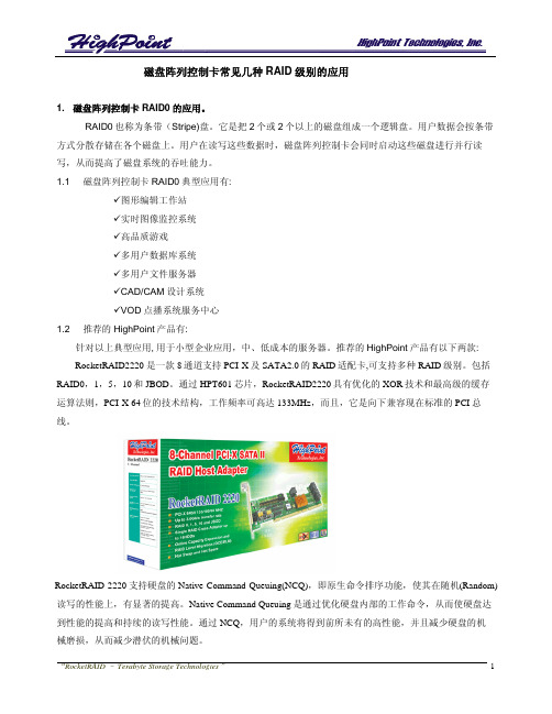
推荐的HighPoint产品有以下两款:RocketRAID2220 是一款8通道支持PCI-X及SATA2.0的RAID适配卡,可支持多种RAID级别。
包括RAID0,1,5,10和JBOD。
通过HPT601芯片,RocketRAID2220具有优化的XOR技术和最高级的缓存运算法则,PCI-X 64位的技术结构,工作频率可高达133MHz,而且,它是向下兼容现在标准的PCI总线。
RocketRAID 2220支持硬盘的Native Command Queuing(NCQ),即原生命令排序功能,使其在随机(Random)读写的性能上,有显著的提高。
Native Command Queuing是通过优化硬盘内部的工作命令,从而使硬盘达到性能的提高和持续的读写性能。
通过NCQ,用户的系统将得到前所未有的高性能,并且减少硬盘的机械磨损,从而减少潜伏的机械问题。
现在越来越多的用户在互联网上通过视频来了解信息,例如网上看电视电影,看体育比赛,通过视频文件来了解有关购房,购物等信息。
互联网时代,只有文字和图片,没有视频肯定是不行的。
尤其是北京08年奥运会的到来,不知道有多少观众甚至国际友人想通过互联网来实现在线观看比赛的愿望。
所以互联网商机也便应运而生,但是,要想把视频资料放到互联网上,对互联网带宽和视频服务器的要求也相对较高。

在Microsoft Windows10上安装HighPoint RAID驱动程序快速安装指南修订版:1.0HighPoint Technologies,Inc.版权版权所有©2012HighPoint Technologies,Inc.本文件包含受国际版权法保护的材料。
保留所有权利。
未经HighPoint Technologies公司明确书面许可,不得以任何形式出于任何目的复制、传播或转录本手册的任何部分。
商标本手册中提及的公司和产品仅供识别之用。
本手册中出现的产品名称或品牌名称可能是也可能不是其各自所有者的注册商标或版权。
在使用HighPoint产品之前备份您的重要数据,使用风险自负。
在任何情况下,HighPoint均不对因HighPoint产品或手册中的任何缺陷或错误导致的任何利润损失或直接、间接、特殊、偶然或后果性损害负责。
本手册中的信息如有更改,恕不另行通知,并不代表HighPoint的承诺。
通知已尽力确保本手册中的信息准确无误。
HighPoint不对本文中包含的技术错误、排印错误或其他错误承担任何责任。
目录在安装驱动程序之前,请考虑以下事项 (4)执行以下步骤以安装Windows8驱动程序 (4)感谢 (8)客户支持 (9)在安装驱动程序之前,请考虑以下事项:▪如果您想使用RocketRAID来进行主存储,则需要确保可引导的分区小于2TB。
你需要把Windows10驱动程序放在USB、CD光盘或DVD光盘上。
▪I果您想使用RocketRAID作为辅助存储器,请从HighPoint网站下载最新的驱动程序,并遵循以下步骤。
请执行以下步骤以安装Windows8驱动程序。
1.启动Windows10操作系统。
右键单击Windows徽标,然后从弹出式菜单中选择“设备管理器”。
图1:设备管理器2.从设备管理器中找到RAID控制器。
右键单击RAID控制器设备,并从弹出窗口中选择“更新驱动程序软件”。
RocketRAID 2340串行ATAⅡ适配卡用户指南版本: 1.0日期: 2005.11HighPoint Technologies, Inc.版权HighPoint技术有限公司2005版权©所有。
该文档中包含的所有内容受《国际著作权法》保护。
如果没有HighPoint公司书面许可,手册中任何部分都不可以被复制、传播或者以任何方式转录。
商标本手册中提到的公司和产品仅仅作为识别。
手册中出现的产品名称或商标名称不可以被再注册或者再注册为其他所有者版权。
在使用HighPoint产品之前请备份您的重要数据以防丢失或者其他不可预测的结果。
任何错误的使用HighPoint产品或手册而导致的利益损失,或者直接的、间接的、特殊的、附带的或相应而生的损失,HighPoint不承担责任。
HighPoint对于任意修改手册中的信息而导致的后果不承担任何责任。
注意HighPoint做了合理的努力以确保手册中信息的正确性。
HighPoint不承担技术错误,印刷或在这里包含的其他错误。
目录用户指南 (1)RocketRAID 2340适配卡介绍 (1)产品特性 (1)RAID概念及术语 (2)RocketRAID 2340硬件描述/安装 (4)RocketRAID 2340硬件 (5)1 – RocketRAID 2340 适配卡外观设计 (5)2 – LED连接 (6)3 – RocketRAID 2340适配卡的安装 (6)4 – 安装确认 (7)RocketRAID 2340 BIOS配置程序 (8)RocketRAID 2340 BIOS配置程序 (9)1 – BIOS命令概述 (9)2 – 磁盘阵列的创建 (10)3 – 备用盘的增加/删除 (11)在Microsoft Windows (2000,XP,2003 Server,x64) 系统下 (12)安装RocketRAID 2340驱动和软件 (12)驱动程序和软件光盘 (13)驱动软盘的创建 (13)安装RAID软件 (14)Windows驱动程序的安装 (15)1 – 安装RAID管理软件/界面概述 (16)2 – 软件接口 – 命令/功能概述 (17)3 – 磁盘阵列的创建 (18)4 – 磁盘阵列的删除 (19)5 – 备用盘的设置 (19)6 – 磁盘阵列的恢复/校验 (19)7 – OCE/ORLM (20)8 – Misc. 磁盘阵列/设备选项 (21)9 – 事件管理 (22)10 – 配置远程系统 (26)11 – 用户和权限的设置 (28)Linux驱动程序支持 (31)Fedora Core 3 Linux安装概述 (32)Red Hat Enterprise 3 安装概述 (35)SuSE Linux Enterprise Server (SLES) 安装概述 (38)FreeBSD驱动程序支持 (41)客户支持 (47)用户指南《RocketRAID 2340串行ATA II适配卡用户指南》提供适配卡性能、安装指导、适配卡RAID阵列的配置和维护。
Dell Precision 3530Solid State Drive Installation GuideNotes, cautions, and warningsNOTE: A NOTE indicates important information that helps you make better use of your product.CAUTION: A CAUTION indicates either potential damage to hardware or loss of data and tells you how to avoid the problem.WARNING: A WARNING indicates a potential for property damage, personal injury, or death.© 2018 Dell Inc. or its subsidiaries. All rights reserved. Dell, EMC, and other trademarks are trademarks of Dell Inc. or its subsidiaries. Other trademarks may be trademarks of their respective owners.2018 - 05Rev. A001 Before you begin (4)Safety instructions (4)Before working inside your computer (4)Safety precautions (5)Electrostatic discharge—ESD protection (5)ESD field service kit (6)Transporting sensitive components (7)After working inside your computer (7)2 Solid State Drive (8)Installing the Solid State Drive (8)3 Getting help (15)Contacting Dell (15)Contents3Before you begin Safety instructionsUse the following safety guidelines to protect your computer from potential damage and to ensure your personal safety. Unless otherwise noted, each procedure included in this document assumes that the following conditions exist:•You have read the safety information that shipped with your computer.•A component can be replaced or, if purchased separately, installed by performing the removal procedure in reverse order. WARNING: Disconnect all power sources before opening the computer cover or panels. After you finish working inside thecomputer, replace all covers, panels, and screws before connecting to the power source.WARNING: Before working inside your computer, read the safety information that shipped with your computer. For additional safety best practices information, see the Regulatory Compliance Homepage at /regulatory_complianceCAUTION: Many repairs may only be done by a certified service technician. You should only perform troubleshooting and simple repairs as authorized in your product documentation, or as directed by the online or telephone service and support team.Damage due to servicing that is not authorized by Dell is not covered by your warranty. Read and follow the safety instructions that came with the product.CAUTION: T o avoid electrostatic discharge, ground yourself by using a wrist grounding strap or by periodically touching an unpainted metal surface at the same time as touching a connector on the back of the computer.CAUTION: Handle components and cards with care. Do not touch the components or contacts on a card. Hold a card by its edges or by its metal mounting bracket. Hold a component such as a processor by its edges, not by its pins.CAUTION: When you disconnect a cable, pull on its connector or on its pull-tab, not on the cable itself. Some cables have connectors with locking tabs; if you are disconnecting this type of cable, press in on the locking tabs before you disconnect the cable. As you pull connectors apart, keep them evenly aligned to avoid bending any connector pins. Also, before you connect acable, ensure that both connectors are correctly oriented and aligned.NOTE: The color of your computer and certain components may appear differently than shown in this document.Before working inside your computer1 Ensure that your work surface is flat and clean to prevent the computer cover from being scratched.2 Turn off your computer.3 If the computer is connected to a docking device (docked), undock it.4 Disconnect all network cables from the computer (if available).CAUTION: If your computer has an RJ45 port, disconnect the network cable by first unplugging the cable from yourcomputer.5 Disconnect your computer and all attached devices from their electrical outlets.6 Open the display.7 Press and hold the power button for few seconds, to ground the system board.CAUTION:To guard against electrical shock unplug your computer from the electrical outlet before performing Step # 8.CAUTION: To avoid electrostatic discharge, ground yourself by using a wrist grounding strap or by periodically touching anunpainted metal surface at the same time as touching a connector on the back of the computer.8 Remove any installed ExpressCards or Smart Cards from the appropriate slots.1 4Before you beginSafety precautionsThe safety precautions chapter details the primary steps to be taken before performing any disassembly instructions.Observe the following safety precautions before you perform any installation or break/fix procedures involving disassembly or reassembly:•Turn off the system and all attached peripherals.•Disconnect the system and all attached peripherals from AC power.•Disconnect all network cables, telephone, and telecommunications lines from the system.•Use an ESD field service kit when working inside any to avoid electrostatic discharge (ESD) damage.•After removing any system component, carefully place the removed component on an anti-static mat.•Wear shoes with non-conductive rubber soles to reduce the chance of getting electrocuted.Standby powerDell products with standby power must be unplugged before you open the case. Systems that incorporate standby power are essentially powered while turned off. The internal power enables the system to be remotely turned on (wake on LAN) and suspended into a sleep mode and has other advanced power management features.Unplugging, pressing and holding the power button for 15 seconds should discharge residual power in the system board.BondingBonding is a method for connecting two or more grounding conductors to the same electrical potential. This is done through the use of a field service electrostatic discharge (ESD) kit. When connecting a bonding wire, ensure that it is connected to bare metal and never to a painted or non-metal surface. The wrist strap should be secure and in full contact with your skin, and ensure that you remove all jewelry such as watches, bracelets, or rings prior to bonding yourself and the equipment.Electrostatic discharge—ESD protectionESD is a major concern when you handle electronic components, especially sensitive components such as expansion cards, processors, memory DIMMs, and system boards. Very slight charges can damage circuits in ways that may not be obvious, such as intermittent problems or a shortened product life span. As the industry pushes for lower power requirements and increased density, ESD protection is an increasing concern.Due to the increased density of semiconductors used in recent Dell products, the sensitivity to static damage is now higher than in previous Dell products. For this reason, some previously approved methods of handling parts are no longer applicable.Two recognized types of ESD damage are catastrophic and intermittent failures.•Catastrophic – Catastrophic failures represent approximately 20 percent of ESD-related failures. The damage causes an immediate and complete loss of device functionality. An example of catastrophic failure is a memory DIMM that has received a static shock and immediately generates a "No POST/No Video" symptom with a beep code emitted for missing or nonfunctional memory.•Intermittent – Intermittent failures represent approximately 80 percent of ESD-related failures. The high rate of intermittent failures means that most of the time when damage occurs, it is not immediately recognizable. The DIMM receives a static shock, but the tracing is merely weakened and does not immediately produce outward symptoms related to the damage. The weakened trace may take weeks or months to melt, and in the meantime may cause degradation of memory integrity, intermittent memory errors, etc.The more difficult type of damage to recognize and troubleshoot is the intermittent (also called latent or "walking wounded") failure. Perform the following steps to prevent ESD damage:•Use a wired ESD wrist strap that is properly grounded. The use of wireless anti-static straps is no longer allowed; they do not provide adequate protection. T ouching the chassis before handling parts does not ensure adequate ESD protection on parts with increased sensitivity to ESD damage.Before you begin5•Handle all static-sensitive components in a static-safe area. If possible, use anti-static floor pads and workbench pads.•When unpacking a static-sensitive component from its shipping carton, do not remove the component from the anti-static packing material until you are ready to install the component. Before unwrapping the anti-static packaging, ensure that you discharge static electricity from your body.•Before transporting a static-sensitive component, place it in an anti-static container or packaging.ESD field service kitThe unmonitored Field Service kit is the most commonly used service kit. Each Field Service kit includes three main components: anti-static mat, wrist strap, and bonding wire.Components of an ESD field service kitThe components of an ESD field service kit are:•Anti-Static Mat – The anti-static mat is dissipative and parts can be placed on it during service procedures. When using an anti-static mat, your wrist strap should be snug and the bonding wire should be connected to the mat and to any bare metal on the system being worked on. Once deployed properly, service parts can be removed from the ESD bag and placed directly on the mat. ESD-sensitive items are safe in your hand, on the ESD mat, in the system, or inside a bag.•Wrist Strap and Bonding Wire – The wrist strap and bonding wire can be either directly connected between your wrist and bare metal on the hardware if the ESD mat is not required, or connected to the anti-static mat to protect hardware that is temporarily placed on the mat. The physical connection of the wrist strap and bonding wire between your skin, the ESD mat, and the hardware is known as bonding. Use only Field Service kits with a wrist strap, mat, and bonding wire. Never use wireless wrist straps. Always be aware that the internal wires of a wrist strap are prone to damage from normal wear and tear, and must be checked regularly with a wrist strap tester in order to avoid accidental ESD hardware damage. It is recommended to test the wrist strap and bonding wire at least once per week.•ESD Wrist Strap T ester – The wires inside of an ESD strap are prone to damage over time. When using an unmonitored kit, it is a best practice to regularly test the strap prior to each service call, and at a minimum, test once per week. A wrist strap tester is the best method for doing this test. If you do not have your own wrist strap tester, check with your regional office to find out if they have one.T o perform the test, plug the wrist-strap's bonding-wire into the tester while it is strapped to your wrist and push the button to test. A green LED is lit if the test is successful; a red LED is lit and an alarm sounds if the test fails.•Insulator Elements – It is critical to keep ESD sensitive devices, such as plastic heat sink casings, away from internal parts that are insulators and often highly charged.•Working Environment – Before deploying the ESD Field Service kit, assess the situation at the customer location. For example, deploying the kit for a server environment is different than for a desktop or portable environment. Servers are typically installed in a rack within a data center; desktops or portables are typically placed on office desks or cubicles. Always look for a large open flat work area that is free of clutter and large enough to deploy the ESD kit with additional space to accommodate the type of system that is being repaired. The workspace should also be free of insulators that can cause an ESD event. On the work area, insulators such as Styrofoam and other plastics should always be moved at least 12 inches or 30 centimeters away from sensitive parts before physically handling any hardware components•ESD Packaging – All ESD-sensitive devices must be shipped and received in static-safe packaging. Metal, static-shielded bags are preferred. However, you should always return the damaged part using the same ESD bag and packaging that the new part arrived in.The ESD bag should be folded over and taped shut and all the same foam packing material should be used in the original box that the new part arrived in. ESD-sensitive devices should be removed from packaging only at an ESD-protected work surface, and parts should never be placed on top of the ESD bag because only the inside of the bag is shielded. Always place parts in your hand, on the ESD mat, in the system, or inside an anti-static bag.•Transporting Sensitive Components – When transporting ESD sensitive components such as replacement parts or parts to be returned to Dell, it is critical to place these parts in anti-static bags for safe transport.ESD protection summaryIt is recommended that all field service technicians use the traditional wired ESD grounding wrist strap and protective anti-static mat at all times when servicing Dell products. In addition, it is critical that technicians keep sensitive parts separate from all insulator parts while performing service and that they use anti-static bags for transporting sensitive components.6Before you beginTransporting sensitive componentsWhen transporting ESD sensitive components such as replacement parts or parts to be returned to Dell, it is critical to place these parts in anti-static bags for safe transport.Lifting equipmentAdhere to the following guidelines when lifting heavy weight equipment:CAUTION: Do not lift greater than 50 pounds. Always obtain additional resources or use a mechanical lifting device.1Get a firm balanced footing. Keep your feet apart for a stable base, and point your toes out.2Tighten stomach muscles. Abdominal muscles support your spine when you lift, offsetting the force of the load.3Lift with your legs, not your back.4Keep the load close. The closer it is to your spine, the less force it exerts on your back.5Keep your back upright, whether lifting or setting down the load. Do not add the weight of your body to the load. Avoid twisting your body and back.6Follow the same techniques in reverse to set the load down.After working inside your computerAfter you complete any replacement procedure, ensure that you connect external devices, cards, and cables before turning on your computer.CAUTION: T o avoid damage to the computer, use only the battery designed for this particular Dell computer. Do not use batteries designed for other Dell computers.1 Connect any external devices, such as a port replicator or media base, and replace any cards, such as an ExpressCard.2 Connect any telephone or network cables to your computer.CAUTION: To connect a network cable, first plug the cable into the network device and then plug it into thecomputer.3 Connect your computer and all attached devices to their electrical outlets.4 Turn on your computer.Before you begin7Solid State DriveInstalling the Solid State Drive1Follow the procedure in Before working inside your computer .2 Remove the base cover:aLoosen the M2.5x5 (8) captive screws that secure the base cover to the system [1].b Pry the base cover from the recess at the top edge [2] and continue prying throughout the outer sides of the base cover inclockwise direction to release the base cover.NOTE:Use a plastic scribe to pry the base cover from the edges.c Lift the base cover from the system.28Solid State Drive3 Remove the battery:a Disconnect the battery cable from the connector on the system board [1] and unroute the cable from the routing channel.b Loosen the M2.5x5 (2) captive screws that secures the battery to the system [2].c Lift the battery away from the system [3].Solid State Drive94 Install the Solid State Drive (SSD) bracket:a Place the SSD bracket into the slot in the system [1].b Replace the M2x3 screw that secures the SSD bracket to the system [2].10Solid State Drive5 Install the SSD:a Insert the SSD into the connector on the system [1].b Replace the M2x3 screw that secures the SSD card to the system [2].c Place the Mylar shield over the SSD [3].Solid State Drive116 Replace the battery:a Insert the battery into the slot on the system [1].b Route the battery cable through the routing channel.c Tighten the M2.5x5 (2) screws to secure the battery to the system [2].d Connect the battery cable to the connector on the system board [3].12Solid State Drive7 Replace the base cover:a Align the base cover with the screw holders on the system [1].b Press the edges of the base cover until it clicks into place.c Tighten the M2.5x5 (8) captive screws to secure the base cover to the system [1].Solid State Drive138 Follow the procedure in After working inside your computer.14Solid State DriveGetting helpContacting DellNOTE: If you do not have an active Internet connection, you can find contact information on your purchase invoice, packing slip, bill, or Dell product catalog.Dell provides several online and telephone-based support and service options. Availability varies by country and product, and some services may not be available in your area. T o contact Dell for sales, technical support, or customer service issues:1Go to /support.2Select your support category.3Verify your country or region in the Choose a Country/Region drop-down list at the bottom of the page.4 Select the appropriate service or support link based on your need.3Getting help 15。
HighPoint Technologies, Inc. (Confidential)HighPoint RocketRAID HighPoint RocketRAID 17401740 SA SATA TA TA Raid 卡部件规格书卡部件规格书REV REV::1.0(以下简称“本规格书”)目 录录一、本规格书适用产品及型号产品型号: HighPoint RocketRAID 1740二、 技术规格产品描述 处理器无SATA 控制器 Marvell 6042板载内存 无 扩展内存 无PCI PCI 32bit@33/66 MHz接口 3.3/5V 通道类型 SATA150通道数量 4自动修复 支持RAID 级别 0,1,5,10,JBOD条带大小设置 支持 控制器cache 控制 不支持 硬盘cache 控制不支持 SAF-TE 支持初始化模式 可选:1、不用初始化,2、正常初始化。
Online Array Expansion支持Online Array Roaming支持 Online Volume Migration 支持 热备功能 支持 电池 无 报警功能有HighPoint Technologies, Inc. (Confidential) 指示灯 有 跳线 无 板卡基材材料 0230物理尺寸 159mm ×64mm挡片 高挡板120mm*18mm/low 挡板80mm*18.4mmPCB 版本 V1.1 管理软件 有(英文界面)工作环境Windows ,Linux ,Unix ,Mac ,RedFlag板卡的其他未描述到的部分见本卡说明书操作三、软件版本四、兼容操作系统具体兼容情况请参照该部件测试报告和兼容列表操作系统Windows 2000 Server 西文版Windows 2000 Server 中文版Windows 2000 Advanced Server 西文版 Windows 2000 Advanced Server 中文版 Windows XP 西文版 Windows XP 中文版 Windows2003 西文版 Windows2003 中文版 Windows Vista Windows 2008Red Hat Enterprise Linux 3.0,3.1,4.0,4.1,4.2,4.3,4.4,5.0 SuSE Linux 8.1 ~ 10.2 Redflag 4.1 adserver FreeBSD 4.3 ~ 6.2MacOS X 10.3.x on Apple PowerMac G4/G5/PRO systems软件 版本号 BIOS V2.0DriverMS-Windows V2.0SuSE linuxV2.2 RedHat linux V2.2FreeBSDV1.02HighPoint Technologies, Inc. (Confidential)五、 IQC 检验指导部件名称SATA RAID 卡 物料编码 MADUHA04序号项 目 项 目 描 述 1 产品型号:HighPoint RocketRAID1740 SATA Raid 卡PCB 号或其他特征标识1 尺寸,认证,PCB 版本87.8mm×64.3mm,REV:V1.1,94V-0,UL2 处理器3 SAS 控制器 Marvell 64454 内存 无5 扩展内存 无6 PCI PCI-E 4X7 接口 3.3/5V8 通道类型 SAS9 通道数量 4 10 FW(Flash) 支持2附件驱动光盘,数据线4根,手册1本,短档片1个六、样品视图RR1740 RAID 卡外观图卡外观图。
ga3530cdn参数
GA3530CDN是一款数码复印机,具有以下参数:
1. 打印速度,GA3530CDN的打印速度为每分钟35页,这意味着它可以快速地处理大量文件并提高工作效率。
2. 分辨率,该复印机的打印分辨率为1200 x 1200 dpi,这意味着它可以产生清晰、高质量的打印文件。
3. 网络功能,GA3530CDN具有网络打印功能,可以通过网络连接多台计算机,实现多人共享打印资源。
4. 纸张处理能力,它支持多种纸张规格和类型,包括普通纸、信封、标签纸等,适应不同的打印需求。
5. 可选配件,该复印机还可以选择配件,如双面打印模块、额外纸盒等,以满足用户不同的功能需求。
总的来说,GA3530CDN是一款功能强大、性能稳定的数码复印机,适用于办公环境中的高效打印需求。
HighPoint 新品速递:RocketRAID 3530
一,产品简介
HighPoint作为专业的存储产品生产商,一直致力于国际存储市场的推广,及存储方案的提供,其新近推出的RocketRAID 3530 RAID 控制卡,更是整合了Intel 强大的IOP(Input/Output processor)控制器以及HighPoint卓著的存储技术,强强联合,从而使RocketRAID 3530 RAID 控制卡拥有了空前的高读写性能和绝对的软/硬件稳定性。
可适用于非编存储系统,硬盘备份,NAS存储系统,视频编辑和近线存储系统等;
基本构造
l TerabyteStream™-Intel ADMA技术
l I ntel IOP 81341(800MHz)
l P CI -Express x8(与x16相兼容)
l板载256 MB ECC DDR II高速缓存
l. 支持12 SATA II/SATA I 硬盘
l支持一机多卡(最多4块RocketRAID 3530)
l I ntel RAID 6 (P+Q)技术
l N VRAM(“写”日志)
l电池备份单元
l板卡整体采用无铅低毒制造工艺
RAID 特性
l支持RAID 0, 1, 3, 5, 6,10, 50and JBOD
l支持多层RAID
l支持多个逻辑磁盘
l支持BIOS启动
l B IOS PnP and BBS (BIOS boot specification)support
l数据的直写或回写
l在线阵列漫游
l在线RAID扩容(OCE) 以及在线RAID级别迁移(ORLM)
l快速/后台初始化新建阵列
l自动检测/识别硬盘,自动执行rebuild动作
l64bit LBA 支持超过2TB的硬盘分驱
l S.M.A.R.T-硬盘状态监视
l硬盘交错启动
l(MAID) 停转空闲硬盘
磁盘阵列监视与预警
l S MTP-邮件通知阵列状态
l蜂鸣器报警
l S AF-TE (I2C) 和SGPIO 状态监视
l S NMP-远程管理
l以太网接口-实现Out of Bound管理(OBM)
l N TP(网络时间协议)
l I ntelli-VRM. (智能RAID管理)
RAID管理
l T erabyteSaver™ and TerabyteGuard™技术保证了数据的高安全可靠性
l操作系统中可更新Firmware
l A PI 库以实现用户定制化
l控制命令行接口(CLI)
l基于Web的RAID管理软件
l硬盘擦洗以防止RAID降级
l自动硬盘坏块监测和修复
l支持ATA pass-through
OS支持
l W indows (2000, XP, x64), 2003, 2008 and Vista (32 and 64 bit)
l L inux
l F reeBSD
l M ac OS X 10.4.x & 10.5.x
l driver 已经嵌入Linux Kernel 2.6.25或以上版本
二,性能
作为一款适用于中高端用户的内置12通道SATA RAID控制卡,RocketRAID 3530为采用Intel 81341 I/O Processor(800MHz),256MB DDRII with ECC板载内存,主机侧为PCI-E X8接口,通过3个内置MiniSAS connector与HDD或硬盘模组相连,使HDD性能得以近乎完美的发挥:
RocketRAID 3530 Performance
Performance(RAID0 12disks) Sequence READ:849.20 MB/s Sequence WRITE:735.55 MB/s
Performance(RAID5 12disks) Sequence READ:763.22 MB/s Sequence WRITE:709.38 MB/s
Performance(RAID6 12disks) Sequence READ:703.42 MB/s Sequence WRITE:617.42MB/s
Performance(RAID3 12disks) Sequence READ:789.93 MB/s Sequence WRITE:704.59MB/s
Performance(RAID1/0 12disks) Sequence READ:800.05 MB/s Sequence WRITE:386.99MB/s
Performance(RAID5/0 12disks) Sequence READ:699.00 MB/s Sequence WRITE:422.12MB/s
三,稳定性
“稳定性”对于使用者来说是至关重要的,任何客户都希望自己使用的存储产品有绝对可靠的稳定性,“数据”是无价的,不可再生的。
为满足广大用户对稳定性越来越高的要求,HighPoint 针对IntelIOP的特性,并依据公司本身在存储行业10几个年头里积累的宝贵经验,开创了一套新的RAID算法和独到的硬件搭配,使RocketRAID 3530的无故障运行时间可与任何同档次的产品相媲美,有过之而无不及。