voith电液转换器使用说明书
- 格式:doc
- 大小:16.89 MB
- 文档页数:20

1 电液转换器原理与调试电液转换器工作原理:(见图)当信号电流I 为零时, 芯棒M 与滑阀O 处于左端极限位置, 压力油腔P 与控制油压A 之间节流口关闭。
A 腔经阀芯中的内孔与回油腔相通,所以A 腔处于卸压状态。
当信号电流(I=4~20mA )增加时,芯棒M 在磁场作用力下,或比例地产生一个向右作用力F ,推动滑阀O 向右移动,使控制油腔A 与回油腔T 的流通面积减小,与压力油腔P 的流通面积增大,根据流量平衡原理,控制油压A 升高,随着油压A 的升高,与A 油腔相通的N 腔压力也升高。
当产生的油压力f 与F 相抵消时,滑阀O 达到平衡,控制油压A 稳定。
A 腔油压值即是成比例地对应输入信号的相应值。
当信号电流减小时,芯棒M 在磁场作用力下,产生一个向左作用力F 。
这时,由于与A 油腔相通的N 腔油压力大于芯棒作用力,滑阀O 向左移动,使得控制油腔A 与回油腔T 的流通面积增大,与压力油腔P 的流通面积减小,控制油压A 降低。
同时,N 腔油压亦降低,芯棒上的磁场力与油压力相等,滑阀达到平衡,控制油压A 稳定。
在手动工作状态,旋动手轮,经传动杆K 推动芯棒M 移动,即能调到所要求的控制油压A 。
一般对应4-20MA 控制电流输出的二次脉冲油压A 为0.15-0.45Mpa ,在这一段范围内控制特性的线形度较高。
电液转换器调试过程:开 始期(允许范围20~30VDC)电液转换器油温 和油压达到要求 带手轮形式的,将手轮转到最左面 根据设计检查电 和油压的连接 将空气从电磁阀 和液压件中排出 提供和测量进油压力(最大40bar) 供 电 源2 否在最小和最大信号变化时,输出电压是否改变 增加信号输出压力是否增加是 否 是提供系统最低的模拟信号测量输出压力 提 供 电 源 提供系统最高的模拟信号利用电液转换器上电位器X1调整所需要的最高压力提供系统最低 的模拟信号 利用电液转换器上电位器 X0调整所需要的最低压力 结 束。


电液转换器原理与调试电液转换器(Electro-Hydraulic Converter)是一种将电能转换为液压能的装置,广泛应用于工业控制系统中。
它的工作原理是通过电信号控制阀门的开关,从而改变液压系统中液压元件的工作状态,实现对液压系统的控制和调节。
液压系统中的元件包括液压缸、液压马达、液压阀等。
通过控制电动机的启动和停止,可以实现对液压泵的启动和停止。
而通过控制液压泵的工作状态和输出压力,可以实现对液压缸等液压元件的运行速度、位置和力度的调节。
为了能够更好地控制液压系统,通常还需要使用电子控制器。
电子控制器通过接收电信号,并进行处理、转换和放大等操作,将电信号转换为适合液压系统的控制信号。
控制信号通过控制液压阀的开关,从而实现对液压系统的精确控制。
调试电液转换器需要根据具体的应用需求和设计要求进行。
首先,需要检查液压系统中液压油的质量和量,确保系统正常工作。
同时,还需要检查液压泵的工作状态和压力参数,确保其输出符合要求。
在调试过程中,还需要对液压系统中的液压元件进行校准。
校准包括对液压阀的开关状态进行调节,以及对液压泵的输出压力和流量进行调节。
调节液压元件的工作参数可以通过改变电子控制器的工作状态和参数实现。
在进行调试时,还需要密切关注液压系统中的压力和流量参数。
通过检测压力和流量的变化情况,可以判断液压系统的工作状态是否正常,以及控制效果是否达到预期。
此外,在调试过程中还需要注意安全问题。
液压系统中会产生高压和高温的工作环境,需要采取相应的安全措施,防止事故发生。
总结起来,电液转换器通过电能转换为液压能,实现对液压系统的控制和调节。
在调试过程中,需要检查液压系统的各项参数,校准液压元件的工作状态,并关注压力和流量的变化情况。
同时,还需要注意安全问题,确保调试过程的顺利进行。
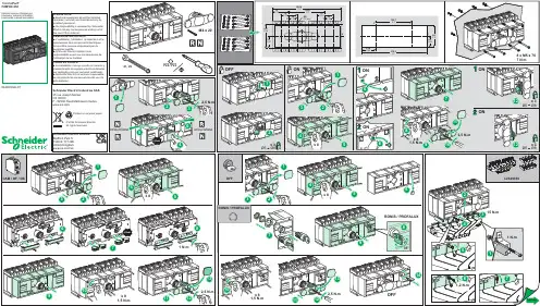
04445322A-07Manual source changeoverInverseur manuel monoblocTransfer PacTFXM100-250Schneider Electric Industries SAS35 rue Joseph MonierCS 30323F - 92506 Rueil Malmaison Cedex© 2022 Schneider Electric.All rights reserved.Printed on recycled paper.TENGA EN CUENTAp La instalación, manejo, puesta en servicio ymantenimiento de equipos eléctricos deberánser realizados sólo por personal cualificado.p Schneider Electric no se hace responsablede ninguna de las consecuencias del uso deeste material.REMARQUE IMPORTANTEp L’installation, l’utilisation, la réparation et lamaintenance des équipements électriquesdoivent être assurés uniquement par dupersonnel qualifié.p Schneider Electric décline touteresponsabilité quant aux conséquences del’utilisation de ce matériel.PLEASE NOTEp Electrical equipment should be installed,operated, serviced, and maintained only byqualified personnel.p No responsibility is assumed by SchneiderElectric for any consequences arising out ofthe use of this material.04445322A-07Transfer PacTFXM320-630Manual source changeoverInverseur manuel monoblocSchneider Electric Industries SAS35 rue Joseph MonierCS 30323F - 92506 Rueil Malmaison Cedex© 2022 Schneider Electric.All rights reserved.Printed on recycled paper.TENGA EN CUENTAp La instalación, manejo, puesta en servicio ymantenimiento de equipos eléctricos deberánser realizados sólo por personal cualificado.p Schneider Electric no se hace responsablede ninguna de las consecuencias del uso deeste material.REMARQUE IMPORTANTEp L’installation, l’utilisation, la réparation et lamaintenance des équipements électriquesdoivent être assurés uniquement par dupersonnel qualifié.p Schneider Electric décline touteresponsabilité quant aux conséquences del’utilisation de ce matériel.PLEASE NOTEp Electrical equipment should be installed,operated, serviced, and maintained only byqualified personnel.p No responsibility is assumed by SchneiderElectric for any consequences arising out ofthe use of this material.。

WOODWARD 505 操作说明一、概述WOODWARD 505 是美国WOODWARD 公司专门为控制汽轮机研制生产的以微处理器为基础的数字式转速调节器。
其特点是控制精度高、稳定性好、操作简便。
可根据每一台汽轮机的特性、参数,以及应用场合,对505进行组态。
其组态直接在WOODWARD 505面板上进行。
二.控制原理WOODWARD505接受二个转速探头(SE)监测的汽轮机转速信号(频率信号), 与内部转速设定值比较,经转速PID放大器作用后, 输出4-20mA操纵信号。
该信号送经电液转换器I/H (1742)转换成二次油压信号(1.5-4.5bar),二次油通过油动机(1910)控制调阀(0801)开度,调节进汽量,调整汽机出力,使汽轮机转速稳定在设定值。
如下图1。
WOODWARD505也接受来自中控室或DCS的转速遥控信号(4-20mA),以使汽轮机转速满足工艺流程的需要(4mA对应xxxrpm,20mA对应xxxrpm)。
WOODWARD505输出一个实际转速信号(4-20mA)用作中控室指示。
汽轮机的启动、暖机、升/降速可以在WOODWARD505面板上完成。
此外汽机旁的电气操作间上,也设置了升速和降速按钮,也可以完成上述功能。
利用WOODWAR505可以进行汽轮机的超速试验。
505面板上会显现报警信号。
WOODWAR505监测到超速时发出一跳闸信号至ESD,ESD控制停机电磁阀, 泄掉速关油,快速关闭速关阀,切断汽源,以保证汽机安全。
三、操作规程。
馈板上调节螺钉,使油动机上指针指示hvmax。
2)使505输出4mA时。
调整电液转换器上电位器×O,使二次油压为1.5bar,再调错油门上调整螺钉,使油动机上指针指示O。
静态整定时,WOODWARD505面板上的操作见图9;电液转换器是德国VOITH公司的产品,能把4-20mA模拟信号转换成符合要求的控制油压。
其调整进程见图10.2.汽机冲转1) 当开机条件具备时进行暖管,2) 用启动装置开启速关阀。
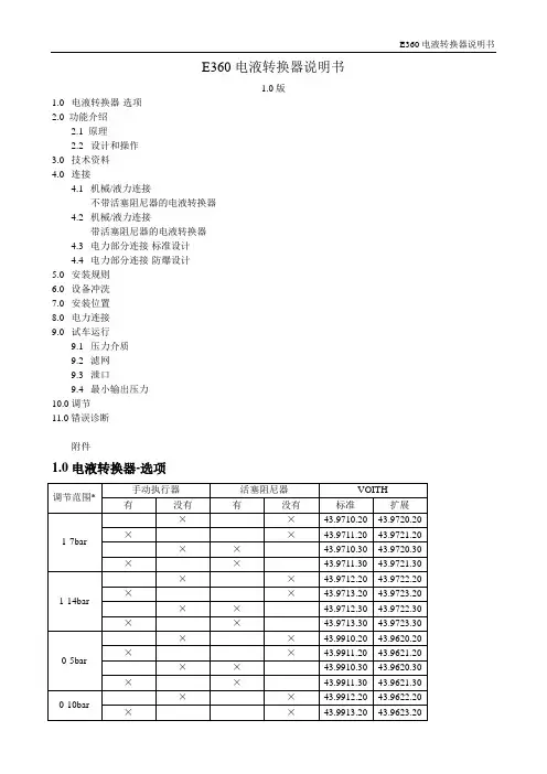
E360电液转换器说明书1.0版1.0 电液转换器-选项2.0 功能介绍2.1 原理2.2 设计和操作3.0 技术资料4.0 连接4.1 机械/液力连接不带活塞阻尼器的电液转换器4.2 机械/液力连接带活塞阻尼器的电液转换器4.3 电力部分连接-标准设计4.4 电力部分连接-防爆设计5.0 安装规则6.0设备冲洗7.0安装位置8.0电力连接9.0试车运行9.1压力介质9.2滤网9.3泄口9.4最小输出压力10.0 调节11.0错误诊断附件1.0 电液转换器-选项*)超出调查范围图概要(看附件):43.9862.21 不带活塞阻尼器标准设计43.9862.30 带活塞阻尼器标准设计43.9631.11 不带活塞阻尼器防爆设计43.9631.30 带活塞阻尼器防爆设计2.0 功能介绍2.1 原理电液转换器充当压力限制电磁阀。
依据一定的准则,电子输入信号被转换成相应的压力信号。
2.2 设计和操作通过两个位置控制器的配合,计算和控制电磁力到预设值。
输出压力作用在一控制动作方向是和电磁力相反的活塞上。
因为选择的控制因素,电磁力是以大约60Hz的频率围绕平均值波动的。
活塞增大或减小控制输入压力管和排管之间相交部分,达到稳定位置。
输出压力正确总是对应当前的信号数据。
手动执行器:电液转换器带手动执行旋钮,即使没有外部辅助电源,操作数据能被设置。
3.0 技术数据3.1 机械/液压数据:装置尺寸:标准设计:参看图no.43.9862.××防爆设计:参看图no.43.9631.××液压连接:参看图:“电液转换器-液压连接”最大输出压力。
(也是设计的可能的最高压力):P=40barI E=0或4mA时最小输出压力:P A0=0barI E=20mA时最大输出压力:P A1=20bar在△P=1bar,T=50℃,粘度=30mm²/s最大排油流速(A→T1)大约45l/min油洁净等级:最大容许污秽等级为NAS1638等级7 或ISO4406 Class 16/13(我们建议滤网最小维持率β6≥200)因为液力振动,我们建议设计使用阻尼活塞。
第30卷 第11期2023年11月仪器仪表用户INSTRUMENTATIONVol.302023 No.11芳烃制冷机组VOITH液力耦合器RWC800M8控制方案丁锦萍,田鸿鹏(岳阳长炼机电工程技术有限公司 宁波分公司,浙江 宁波 315812)摘 要:某炼油化工厂芳烃装置乙烯制冷机组液力耦合器采用VOITH 公司的增速型液力耦合器RWC800M8,其在国内应用较少。
本文简要介绍了VOITH 公司的增速型液力耦合器的基本原理,针对耦合器Vorecon 控制单元控制方案进行介绍,从现场Vorecon 至VCU 控制器PLC,VCU 控制器至CCS 控制系统,实现调速方案,达到优化控制。
总结了该控制方案在实际应用中出现的问题,提出相应的解决方案。
实际应用表明,该系统调试稳定可靠,操作简便。
同时,对耦合器附属轴系仪表调试方法进行总结,方便日常维护。
关键词:液力耦合器;VCU ;控制系统;转速;CCS中图分类号:TE967.03 文献标志码:AThe RWC800M8 Control Scheme of VOITH Hydraulic CouplerDing Jinping ,Tian Hongpeng(Y ueyang Changlian Electromechanical Engineering T echnology Co., Ltd., Ningbo Branch,Zhejiang, Ningbo,315812,China )Abstract:The hydraulic coupler of the ethylene refrigeration unit in an aromatics plant of a certain refinery adopts the growth rate hydraulic coupler from VOETH company, RWC800M8. There are few domestic applications, and a brief introduction is given to the basic principle of VOITH Company’s speed increasing hydraulic coupler. Introduce the control scheme of the coupler Vorecon control unit, from on-site Vorecon to VCU controller PLC, VCU controller to CCS control system, to achieve speed regulation scheme and optimize control. Summarized the problems encountered in the practical application of this control scheme and proposed corresponding solutions. The practical application shows that the system debugging is stable, reliable, and easy to operate. At the same time, summarize the debugging methods of the coupling accessory shaft system instrument for convenient daily maintenance.Key words:hydraulic coupler ;VCU ;control system ;speed ;CCS收稿日期:2023-08-21作者简介:丁锦萍(1986-),女,湖南岳阳人,大专,工程师,从事石油化工仪表运维工作。
转换器使用说明书亲爱的用户,感谢您选择本公司的产品和服务。
对技术完美性的追求是我们的目标,我们的理念是产品不求多,只求精。
请您在使用本机前详细阅读此说明书,以便方便您安装使用。
注意:本手册未经本公司的许可,不得任意复制、拷贝、翻译或以其他形式进行发送。
本手册所提及的商标和名称皆属本公司所有。
未经本公司许可而对产品及本说明书进行修改所造成的产品功能不实现、损伤或对其他产品、人造成的影响,本公司将不负任何责任。
对于以合法渠道取得本公司产品的用户,本公司将提供三个月保换、一年保修的服务,但不包括操作不当,人为原因的故障及伤害。
本手册若有任何内容修改或变更,将不另行通知。
XX年X月版本:V4.0一、系统简介XX转换器型设备1~8条E1电路点对点地传输以太网MAC帧数据,设计最高传输速率可达16.384Mbps。
设备不仅提供了线路侧、以太网侧完备的告警指示,而且提供了包括线路的误码率统计,以太网数据流量统计等全面的管理信息,便于构建可统一运营的接入网。
二、技术特性1,实现1-8路E1通道承载100M以太网数据。
2,以太网接口标准的MII接口,只支持100M,全双工工作模式;内置流量统计,可汇报给网管以太网收发的流量统计和错包率等信息;对超长、超短和CRC错包进行过滤;最大支持2036字节的超长包;支持PAUSE流量控制功能;可通过以太网进行管理(可选)3,线路接口1-8路E1通道。
必须成对使用,但可以不对称使用;自动检测可用通道数目,该通道数据也可以通过网管关断;具有AIS、LOS、LOF和误码率告警,其中误码率的具体数据可以通过网管查询;误码关断及误码门限可由网管设置;支持远端环回,支持线路通道误码检测(利用HDLC控制帧);发起远端环回时,禁止向以太网侧发送数据;可检测外部E1环回,禁止向以太网侧发送数据;XX码型4,网管支持XX网管。
可通过以太网进行管理;8bits设备地址输入,最多统一管理256个设备网管信息全面,包括本端和远端的各E1线路状态,以太网端口信息和流量统计。
调试说明基本的设定可以在就地控制面板完成,这种设定可以不使用PC机直接在电动执行机构上完成。
仅使用适当的结构程序就可以完成执行器的设定。
9.1就地控制面板设定9.1.1操作按钮1、写保护开关2、全开显示灯3、驱动按钮4、复位5、电源灯6、联机计算机用RS-232接口7、系统保护地8、全关显示灯9、全关确定10、全开确定执行机构行程未在出厂时设定9.1.2 调试前的准备---送电源---写保护开关置“OFF”位---选择“MAN”操作模式(选择MAN模式,1无输入信号) ---接线正确(如接线不正确全开与全关灯均以4Hz频闪)9.1.3 设定步骤--卸掉就地控制面板保护罩螺丝--将保护罩掀到一边进入设定模式9.1.3.1--同时按“3”按钮5秒钟,直到全开与全关显示灯都以4Hz 频闪9.1.3.2设定全开或全关--按开或关(3按钮)到需要位置(全开或全关位)--按(10)或(9)确定开关位置,当系统确定此(比如开位)位置时,一灯(开灯)以1Hz频闪,另一灯(关灯)以4Hz频闪9.1.3.3设定另一位置(全关或全开)---按关或开(3按钮)到需要位置(全关或全开位)---按(9)或(10)确定关开位置,此时,开关灯均以1Hz频闪9.1.3.4存储设定---同时按下(9)和(10),(2)(8)灯在很短时间内同时亮,设定结束。
---若对于执行器来说行程过短,(2)(8)灯均再次以4Hz频闪,此时应重复设定已获得加大行程(行程大小参考执行器分类型号)9.1.3.5设定后的修正如未存储,按RESERT键重设如在存储后更改,需重复整个设定过程接线图:开反馈:12 13 关反馈:10 11指令:26(+)27(-)反馈:30(+)31(-)Electronics in mode “MAN”(No signal at BE1)需要14和1短接,15和2短接。
注意:此电机为4.5VAC . 虽然里面标有U V W的字样。

Proven reliabilityThe full bridge plus toroidal transformer topology has proven its reliability over many years.The inverters are short circuit proof and protected against overheating, whether due to overload or high ambient temperature.High start-up powerNeeded to start loads such as power converters for LED lamps, halogen lamps, or electric tools.ECO modeWhen in ECO mode, the inverter will switch to standby when the load decreases below a pre-set value (min load: 15 W). Once in standby, the inverter will switch on for a short period (adjustable, default: every 2,5 seconds). If the load exceeds a pre-set level, the inverter will remain on.PWM solar chargerThe solar charger ensures that the batteries are charged by energy harvested from your solar panels. The charge algorithm is programmable.Remote on/offThe Phoenix Inverter Control VE.Direct Remote panel (not included) can be used to turn the inverter on or off remotely. Alternatively, a remote on/off switch can be connected to a two-pole connector or between battery plus and the left-hand contact of the two-pole connector.LED diagnosisPlease see the manual for a description.BluetoothThe inverter and solar charger parameters can be read, monitored, and configured via Bluetooth using the VictronConnect app.VE.Direct communication portThe VE.Direct Port can be used for connection to a GX device, GlobalLink 520 for monitoring via the VRM portal or for connection to a computer for monitoring or configuring using the VictronConnect app.Monitoring via the VictronConnect app or GX device: • Inverter in- and output voltage and % load • Solar power, voltage, and current • Operational state and alarmsFully configurable via the VictronConnect app: • Low battery voltage alarm trip and reset levels • Low battery voltage cut-off and restart levels • Dynamic cut-off: load dependent cut-off level• Output voltage 210 – 245 V and Frequency 50 Hz or 60 Hz • ECO mode on/off and ECO mode sense level • Battery charge current, algorithm, and voltages• Battery charge temperature compensation or low temperature cut of levelTo transfer the load to another AC source: the automatic transfer switchFor our low-power inverters, we recommend our Filax Automatic Transfer Switch. The Filax features a very short switchover time (less than 20 milliseconds) so that computers and other electronic equipment will continue to operate without disruption.DC and PV connections with screw terminalsNo special cable terminals or tools are needed for installation.Available with an IEC-320 socket An IEC-320 male plug is included.Sun Inverter 12/250Sun Inverter 12/250IEC-320 socketThe VictronConnect appVictron Energy B.V. | De Paal 35 | 1351 JG Almere | The Netherlands E-mail: *********************** | Cont. power at 25 °C (1)250 VACont. power at 25 °C / 40 °C 200 W / 175 WPeak power 400 WAC output voltage / frequency (adjustable) 230 Vac +/- 3 % 50Hz or 60Hz +/- 0.1 %DC input voltage range 9.2 – 17 V 18.4 – 34.0 VDC low shut down (adjustable) 9.3 V 18.6 VDynamic (load dependent) DC low shut down Configurable via the “dynamic cut-off” settingDC low restart and alarm (adjustable) 10.9 V 21.8 VBattery charged detect (adjustable) 14.0 V 28.0 VMax. efficiency 87 % 88 %Zero-load power 4.2 W 5.2 WDefault zero-load power in ECO mode (2) 0.8 W 1.3 WSolar charger technology Pulse Width Modulation (PWM)Maximum PV voltage current and power 25 V / 15 A / 375 W 50 V / 10 A / 500 WSolar panel type 36 cell solar panel 72 cell solar panel or two 36 cell solar panels in series Charge voltages Adjustable and able to be temperature compensated (3)Protections (4) a - fOperating temperature range -40 to +60 °C (fan assisted cooling) / Output power deration: 1.25 % per °C above 40 °CHumidity (non-condensing) max 95 %Bluetooth wireless communication For remote monitoring and configurationVE.Direct communication port For remote monitoring and system integrationMaterial & Colour Steel chassis and plastic cover (blue RAL 5012)Battery-connection Screw terminals, maximum cable cross-section10 mm² / AWG 8PV-connection Screw terminals, maximum cable cross-section 4 mm² / AWG 12Standard AC outlet IEC-320 (male plug included)Protection category IP 21Weight 2.4 kg / 5.3 lbsDimensions (h x w x d) 86 x 165 x 260 mm / 3.4 x 6.5 x 10.2 inchRemote on-off YesAutomatic transfer switch FilaxSafety EN-IEC 60335-1 / EN-IEC 62109-1EMC EN 55014-1 / EN 55014-2 / IEC 61000-6-1 / IEC 61000-6-3Automotive Directive ECE R10-4 EN 50498(1) Nonlinear load, crest factor 3:1(2) The default ECO mode retry interval is 2.5 s.The retry interval, stop power level, and startpower level are adjustable.(3) Temperature compensation via an optional”Temperature sensor Quattro, MultiPlus andGX Device” or the “Smart Battery Sense”.(4) Protection key:a) output short circuitb) overloadc) battery voltage too highd) battery voltage too lowe) temperature too highf) DC ripple too highBattery temperature sensorsIf battery charge temperature compensation or a low temperaturecharging cut of level is needed use the ”Temperature sensorQuattro, MultiPlus and GX Device” or the “Smart Battery Sense”temperature sensor.Phoenix Inverter Control VE.Direct Remote panelThis panel can be used for remote on/off control of the SunInverter.Battery MonitorsThe BMV or SmartShunt Battery monitor keep track of the batterystate of charge, voltage, current, consumed Ah or time to go. Themonitor also stores a host of data regarding performance and useof the battery.Remote monitoringThe Sun Inverter can be connected via its VE.Direct port to aGlobalLink 520 or a GX device, like the Cerbo GX, and then beremotely monitored via the VRM portal.。
VOITH阀控式液力偶合器电控系统要求设备选型原则:1、主机选用市面上常见的通用型PLC,如AB、SIEMENS等;其它辅助元件优先选用进口件;各种I/O点数应有适当预留,以备系统将来扩充。
2、程序编制:必须严格按照VOITH公司提供的逻辑控制框图进行程序编制。
3、整个PLC系统必须符合国家规定的煤矿井下防爆要求,施工方需有相应的施工资质。
4、施工方需提供现场调试服务。
5、供货期:2个月VOITH控制逻辑说明注意1562DTPPWL2E设备和I/O列表1.1由VOITH提供的设备1.1.1阀块主体(mainfold)型号STB3/700(D1)1.1.1.1充液阀,两位两通(2/2way)(常闭,失电时闭合)ATEX(无源节点)直流12VDC供电,电源和隔离栅非VOITH供货(最大150mA)1.1.1.2排液阀,两位三通(3/2way)(失电状态—排液)12VDC供电,无源节点,本安电源和隔离栅非VOITH供货(最大150mA)1.1.1.3充液阀确认返回节点“RMK”,带有常开和常闭返回节点,建议使用常开节点,节点打开表示阀在失电状态(非充液状态)1.1.1.4排液阀确认返回节点“RMK”,带有常开和常闭返回节点,建议使用常开节点,节点打开表示阀在失电状态(排液液状态)1.1.1.5100%液位满压力开关(SPDT节点(开关量),当水位达到100%充满时动作)1.1.1.5.1(开关量)2预启动和启动闭锁2.1检查运输机的启动条件,如张力等,启动2.2检查耦合器的供水压力,如果供水压力小于4Bar,停止启动,显示“启动时供水压力小于4Bar”2.3在电机启动期间,充液阀和排液阀都失电,即保持排液状态,3启动电机&保持排液状态3.1所有的闭锁,预警,报警,都正常后,首先启动尾电机,尾电机启动2-3秒后启动头电机3.2最后一个电机启动两秒后记录每一个电机电流,3.3保持充液和排液阀失电状态,这种状态保持到电机电流下降到空载电流(指示耦合器在排空状态)3.4如果20秒后电机还没达到空载电流,停车,显示“电机启动时电流高”3.5所有电机电流达到空载电流后,进入下一个“加速段”3.6推荐设置的空载电流应稍高于实际的空载电流,以适应电压下降时的电机电流的增加,可以设置高于5%,且通过软件可调4AFC启动&初始充液段4.1注意:在DTPKWL2E耦合器内部集成一个流量控制阀,这个设备使用内部提供4.2所有驱动的充液阀得电2秒后,检查供水压力,程序使用一个最大的循环时间来保持充液阀充液状态来保证不过充,用下面的方法选择充液时间(充液时间应用软件可调节)4.2.1供水压力在4~16Bar时,充液时间为15秒(最大可调整到25秒)4.2.2供水压力1~4Bar时,充液时间为30秒(最大可调整到50秒)4.2.3供水压力小于1Bar时,停车并显示“充水压力低”4.2.4供水压力大于16Bar时,充液时间为15秒(最大可调整到50秒)报警显示“充水压力高”4.2.5供水压力大于20Bar时,停车并显示“充水压力太高”4.3当接到AFC启动的指令时,尾电机的充液阀,排液阀同时得电,不再改变充液循环时间,在AFC启动期间,不进行超温换水循环,不考虑RTD的温度指示。
电源转换器使用说明书使用您的转换器前,请仔细阅读使用说明书安全第一安装或使用不当都有可能有为危险或造成意外伤害。
使用前,请仔细阅读说明书,特别要注意警告和注意部分的内容。
注意提示您在一定条件下或一些操作方法可能对转换器或其他设施带来危害;警告提示您某些情况可能引起人身伤害。
警告:触电危险,儿童远离1.交流输出插座与一般家电插座一样,有潜在危险,可以致命。
2.插座、风扇、或通风口不能堵塞。
3.转换器不能浸水、雨淋、淋雨雪。
4.普通 AC 电线无论如何都不能直接与转换器连接。
警告:表面发热连续使用后壳体表面温度会上升到60 ℃。
使用时,保证少于 2 个端面 5CM 内气体通畅。
易变高温影响的物体不要放在附近。
警告:爆炸危险下列环境中禁止使用:附近有易燃、易爆物品,以汽油为动力的船舱底部,丙烷存储罐附近,存放汽车轮胎或铅酸电池的地方。
电池会由于氢气渗漏,一旦接触静电火花,易被点燃。
使用时,确保遇到意外情况,能就近得到援助。
注意:1.不能将带电的直流电源直接插入转换器。
2.不能将接地的直流负载接入转换器。
3.不能在超过60 ℃的环境下工作。
1.说明感谢您购买500W电源转换器。
这款转换器体积轻巧,设计合理,代表着高频转换的新潮流。
无论接在汽车、船或24V 专用电瓶上,它都能为家用电器如电视机、录像机、电动工具等提供安全可靠的交流电源。
设有自动保护功能,使您的转换器、电瓶在超常负载下得到有效保护,方便实用。
请在安装和操作之前仔细阅读本说明书。
说明书留存以备参考。
安全特性:1.过载保护,电流自动切断。
2.内置式保险丝,重新启动时,提供安全保障。
3.低电压保护后,电源自动切断。
4.过温保护后,电源自动切断。
5.输出短路保护。
2.安装指南基于安全和性能的考虑,安装环境应具备条件:1.干燥:不能浸水或雨淋2.阴凉:适合温度在-25 ℃与 40℃之间环境中使用。
3.通风:不能与电池驱动的电器连接,安装环境周围不能有易燃液体如汽油和挥发性的易爆气体。
H-Track H-Track – A Compact Hybrid of Superior PerformanceMore Power in Less SpaceH-Track electro-hydraulic actuators feature the smallest mounting envelope in their class with a patented valve and reservoir design that provides significant space savings compared to competitive models. H-Track is a robust linear actuator providing force up to 4800 lbf (21350 N) and travel speeds near 4 in (100 mm) per second. With stroke lengths up to 16 in (406 mm), end switch options and multiple configurations available, the H-Track offers a unique set of options for machine designers.Made for Tough ConditionsH-Track actuators are weatherproof, dust tight, corrosion resistant, and IP67 static (temporary submersion) and IP69K (high-pressure washdown) tested. The H-Track offers an optional operation temperature as low as -40°F (-40°C) to as high as 180°F (82°C), making it an ideal option for use in demanding conditions.H-Track electro-hydraulic actuators provide the high-load performance of hydraulics without the expansive space requirements nor the prohibitive cost of full-sized, fluid-based systems.H-Track Completely Self-ContainedThe motor, pump and valves are contained in one mini power pack mounted directly to the combined cylinder/fluid tank. This means that the inner workings are completely sealed from the outside, allowing this unique arrangement to minimize parts and improve performance. Unlike hydraulic cylinders, there is no need for external hoses, valves, reservoirs or hydraulic connectors that can break or leak. The operation is as simple as with a traditional electric actuator - just turn the supply voltage onto move and change polarity to reverse direction.If necessary, the actuator extension tube can be manually overridden, allowing the tube to float foroperating in emergency situations.3Electro-Hydraulic AdvantagesThe best features from the electric and hydraulic actuator worlds have been chosen to power the H-Track linear actuator, giving it a unique set of capabilities that allow it to be used in applications that otherwise might be too difficult for other solutions to take on.Compact DesignH-Track actuators have a mounting length that is shorter than any other electromechanical actuator on the market. It can fit into applications with a pin-to-pin length as small as 4.8 in (122 mm) plus its stroke, and still provide up to 4800 lbf (21350 N) of force.Superb Load Holding PowerH-Track actuators operate in both tension and compression and will hold a load stationary without power in either direction. Static load holding capability will always exceed the dynamic load moving capability.Vibration and Shock Load ResistantH-Track actuators are immune to vibrational drifting, hydraulically self lock and safely absorb shocks. Energy EfficientElectric control provides clean, smooth linear motion without hydraulic plumbing or other expensive componentry. The H-Track’s power demands are significantly less than those of a full hydraulic system as the actuators require power only when in motion. Solid Extension TubeSince the extension tube is solid, it allows for increased resistance to buckling compared to a hollowextension tube of the same size.5H-Track Hydraulics Isolated from the Atmosphere The fluid reservoir is vented and isolated from the atmosphere with a flexible lid, allowing actuator and pump operation in any orientation without entraining or cavitation.Maintenance-FreeH-Track actuators require no lubrication, hydraulic fluid fillup, or any other type of maintenance or adjustments for their entire lifecycle.Contamination-FreeThe H-Track pump is burnished, cleaned, flushed and vacuum filled with degassed hydraulic fluid. The system is completely sealed with no hoses to leak. This ensures you enjoy contaminant-free performance for the life of the actuator.Thoroughly TestedThroughout their entire development process, H-Track actuators are rigorously tested to ensure they meet all relevant standards and performance specifications prior to leaving the factory. Please contact Thomson customer support to learn more about which standards H-Track meets and how our testing is carried out.CustomizationAs with most Thomson products, H-Track actuators can be customized. Our engineers will work with you to determine the modifications needed – from a simple color change to a complete overhaul of the design. Thomson is a global leader in custom actuator production and takes pride in supplying the optimal solution to each customer.6Built to PerformH-Track is one of the strongest actuators for its size without compromising life expectancy or the ability to withstand the elements.1Compact and strong power pack unit, containing pump, valve and motor 2Fluid tank integrated into the cover tube3Solid small-diameter, buckling-resistant extension tube312Get the best from the electric and hydraulic worlds in one package. H-Track is powerful, tough, and vibration and shock load resistant.Yet it only needs a battery and a switch to run, requires no maintenance, and minimizes the risks and hazards associated with hydraulic fluid leaks.4Power pack unit completely sealed from the outside 5Two-wire operationLarge number of power pack and cylinder configurations allow for great design flexibility4 685H-Track is built from the outside in to excel in situations where many otheractuators are forced to bow out. The unique electro-hydraulic design combines the best features from two distinct systems and opens up new application possibilities for linear actuators.7H-Track 410H-Track is designed and tested to operate under the harshest conditions without failure or the need for maintenance.10IP69K/IP67 protection class 13Large operating temperature range 11Chrome finished steel extension tube 14High shock load and vibration resistance 12Salt spray tested for 200 hoursAnodized aluminum alloy housing1912101178211976Built for the Toughest ApplicationsWith a self-contained electro-hydraulic system, H-Track actuators meet the growing demand for power-dense performance used in a variety of industrial applications, including agricultural sprayer booms, snow plow blades and mower deck lifts.Designed to Withstand Life on the FieldsWith agricultural sprayers becoming larger and boom lengths reaching up to 177 ft (54 m), strain on the actuators has increased exponentially. Actuators are used to fold the long sprayer booms from an extended position to a stowed position for transport. The folding and unfolding of these booms apply very high loads on the actuators. The strain on the units is dramatically increased when the sprayeris in motion and the bouncing of the booms causes even more extreme loads. These combined loads create tremendous impact force that can easily destroy most other electric actuators. The H-Track is designed to handle this type of loading with ease.8H-Track Ideal for Demanding Outdoor ApplicationsWhere the often harsh outdoor environmentcreates conditions that can be fatal for mostactuators, the H-Track thrives. A snow plowbattling icy roads and striking a stationary, concreteobject is an example that would quickly destroymost linear actuators. The H- T rack’s unique valveand reservoir design gives it the ability to cushionthese blows and continue operating without issue.The optional ability to operate in temperatures aslow as -40°F (-40°C) makes it a perfect fit for eventhe coldest climates. Mower deck lifts are typicallywhere electric actuators shine, but with increasingdeck sizes and ground speeds, the limits of thesetraditional actuators are being exceeded. Withits reliable, load-holding capabilities, enhanceddurability for higher transport speeds, and ability towithstand high-pressure washdowns, the H-Trackis a perfect choice for the next generation of larger,faster mowers.9Technical FeaturesH-Track Electro-Hydraulic Linear Actuator • Combines the best from the hydraulic and electric worlds.• High power density.• Very compact and short pin-to-pin versus stroke length relationship.• Solid extension tube allows for increased resistance to buckling.• Immune to vibrational drifting and hydraulically self locks.• High shock load and vibration resistance.• Fluid reservoir is vented and isolated from the atmosphere with a flexible lid, allowing actuator and pump operation in any orientation withoutentraining or cavitation.• Standard strokes up to 16 in (406 mm).• Designed for harsh outdoor conditions.•Reliable and maintenance free.H-TrackTechnical SpecificationsElectrical ConnectionsF FuseS1 Double pole double throw switchTo extend the actuator, apply +Vdc to black (white) and -Vdc to grey (green/white). To retract, apply-Vdc to black (white) and +Vdc to grey (green/white). Colors in between brackets are valid for the 560 W motor. Avoid running the actuator in to the ends.DimensionsH-Track DimensionsWeightbut at temperatures below 40°F (4°C), force and current begin to increase, while speed decreases. At temperatures above 120°F (50°C), speed will decrease slightly. The exact amount of performance change is difficult to calculate. Also, when it comes to the lower temperature span, the performance will move towards what is stated above as the temperature rises in the actuator due to the heat generated by its work. Please consult Thomson customer service for more information.Performance MatrixH-Track Ordering KeySizing and SelectionIn order to choose the optimal H-Track actuator for your application, please follow the sizing and selection process as described below. Do not hesitate to contact Thomson customer support if you need assistance.Step 1. Determining Load ConfigurationDetermine which load configuration (C, H, N or B) is valid for your application. Also see page 18.Example: Assuming that the load needs to be pushed horizontally, and the extenson tube will not be affected by gravity when pushing or pulling, then the application corresponds to load configuration N.Step 2. Bore and Extension Tube SizingDetermine which bore size is needed for your load and stroke. Also see page 19.Example: Assuming the application requires 16-in stroke, and that load is 2500 lbf at extension (red dot) and 500 lbf at retraction (yellow dot), then the Stroke vs. Load and Bore Size diagram below shows, that only the blue curve is above both points. Therefore, bore size H3 is the only possible choice in this case.Stroke vs. Load and Bore SizeStroke [in]Bore SizeH1H2H3L o a d [l b f (N )]0 2 4 6 8 10 12 14 16 18 20 22 245500 (24464)5000 (22240)4500 (20016)4000 (17792)3500 (13344)3000 (13344)2000 (8896)1500 (6672)1000 (4448)500 (2224)H-TrackStep 3. Sizing of Motor, Pump and Power Supply Determine the size of the actuator motorand pump for your application, as wellas the current draw by referring to the diagrams on pages 20 - 22.Example: Since the load configuration in step 1 was determined to be of type N, refer to the diagrams on page 22.In the Load vs. Speed diagrams for load configuration N, the maximum extension and retraction loads that were assumed in step 2 are shown by the vertical lines. In this example, we also assume that a travel speed of 0.25 in/s is required when extending and 1 in/s when retracting. The only H3 bore size of the four that can deliver that speed when extending at 2500 lbf and retracting at 500 lbf is model H3N-xx-2B23.In order to size the power supply, you must decide which voltage to use and themaximum load currect draw at extensionand retraction. To do that, first determine the percentage of the maximum permissible load that is used in each direction.According to the Load vs. Speed diagram, H3N-xx-2B23 has a maximum load of about 2700 lbf at extension and 2000 lbf at retraction (the exact max. load values can be found in the Performance Matrix on page 14). The assumed maximum loads needed in the application, which requires 2500 lbf at extension and 500 lbf at retraction, are about 92% (red line) and 25% (yellow line) of the maximum permissible loads. The current forH3N-xx-2B23 equipped with a 24 Vdc motor (model H3N-24-2B2) would, in this case, follow the dotted red line and be about 20 A at extension and 40 A at retraction. Be sure to size your power supply with some margin.Step 4. Finishing the Ordering CodeAt this point, the ordering code is H3N-24-2B23-xxxx. In order to complete it, the type of extension tube front adapter, the stroke length and the rear adapter orientation need to be determined. Also see page 15.Example: In step 2, it was assumed the application required a 16-in stroke, which means the code becomes H3N-24-2B23-x16x. If we assume a standard front adapter and a 90° rear adapter orientation are required, the complete ordering code would be H3N-24-2B23-A16R.Load vs. Speed @ Extension Load vs. Speed @ RetractionC u r r e n t [A ]S p e e d [i n /s (m m /s )]Load [lbf (N)]12 Vdc Actuators Bore Size H124 Vdc Actuators Bore Size H248 Vdc ActuatorsBore Size H3Percent of Maximum Permissible Load [%]H1N-xx-1B11 H1N-xx-1B41H1N-xx-2B11H1N-xx-2B41HxN-12-1xxx HxN-12-2xxx HxN-24-1xxx HxN-24-2xxx HxN-48-1xxxHxN-48-2xxx H2N-xx-1A12 H2N-xx-1B42H2N-xx-2A22H2N-xx-2B32H3N-xx-1A13 H3N-xx-1B23H3N-xx-2A13H3N-xx-2B23Load vs. CurrentDetermining Load ConfigurationThere are four main types of load and gravity configurations, which will determine the performance of the actuator. Please refer to the configurations below and choose the one that best corresponds to your application. Contact Thomson customer support if you are unable to determine a valid configuration for your application.Configuration CThe gravity resists the load being moved when the actuator extends and helps it when retracting. Configuration NThe gravity does not affect the load in any direction.Configuration HThe gravity helps the load being moved when the actuator extends and resists it when retracting.Configuration BThe gravity both helps and resists the load being moved in both directions except at one point where the load is not affected by the gravity at all. If this is your configuration, try to re-design the mechanical linkage so that the result is a C, H or N configuration. Please contact Thomson customer support if that is not possible.H-TrackSizing of Bore and Extension TubeStroke vs. Load and Bore SizeStroke [in]Bore SizeH1H2H3L o a d [l b f (N )]0 2 4 6 8 10 12 14 16 18 20 22 245500 (24464)5000 (22240)4500 (20016)4000 (17792)3500 (13344)3000 (13344)2500 (11120) 2000 (8896)1500 (6672)1000 (4448)500 (2224)The maximum load in each direction and the required stroke length determine the minimum bore and extension tube size needed for the actuator. Refer to the diagram below todetermine which bore size your application requires. If no solution exists, the stroke and/or load must be reduced. Contact Thomson customer support if you are unable to determine a valid combination for your application.Sizing of Motor, Pump and Power SupplyLoad vs. Speed @ ExtensionLoad vs. Speed @ RetractionC u r r e n t [A ]S p e e d [i n /s (m m /s )]Load [lbf (N)]12 Vdc ActuatorsBore Size H124 Vdc ActuatorsBore Size H248 Vdc ActuatorsBore Size H3Percent of Maximum Permissible Load [%]H1C-xx-1B11 H1C-xx-1B41H1C-xx-2B11H1C-xx-2B41HxC-12-1xxx HxC-12-2xxxHxC-24-1xxx HxC-24-2xxxHxC-48-1xxx HxC-48-2xxxH2C-xx-1A12 H2C-xx-1B32H2C-xx-2A22H2C-xx-2B32H3C-xx-1A13 H3C-xx-1B23H3C-xx-2A13H3C-xx-2B23Load vs. Current21H-TrackSizing of Motor, Pump and Power SupplyLoad vs. Speed @ ExtensionLoad vs. Speed @ RetractionC u r r e n t [A ]S p e e d [i n /s (m m /s )]Load [lbf (N)]12 Vdc ActuatorsBore Size H124 Vdc ActuatorsBore Size H248 Vdc ActuatorsBore Size H3Percent of Maximum Permissible Load [%]H1H-xx-1B11 H1H-xx-1B41H1H-xx-2B11H1H-xx-2B41HxH-12-1xxx HxH-12-2xxxHxH-24-1xxx HxH-24-2xxxHxH-48-1xxx HxH-48-2xxxH2H-xx-1A12 H2H-xx-1B32H2H-xx-2A22H2H-xx-2B32H3H-xx-1A13 H3H-xx-1B23H3H-xx-2A13H3H-xx-2B23Load vs. Current22Sizing of Motor, Pump and Power SupplyLoad vs. Speed @ ExtensionLoad vs. Speed @ RetractionC u r r e n t [A ]S p e e d [i n /s (m m /s )]Load [lbf (N)]12 Vdc ActuatorsBore Size H124 Vdc ActuatorsBore Size H248 Vdc ActuatorsBore Size H3Percent of Maximum Permissible Load [%]H1N-xx-1B11 H1N-xx-1B41H1N-xx-2B11H1N-xx-2B41HxN-12-1xxx HxN-12-2xxxHxN-24-1xxx HxN-24-2xxxHxN-48-1xxx HxN-48-2xxxH2N-xx-1A12 H2N-xx-1B32H2N-xx-2A22H2N-xx-2B32H3N-xx-1A13 H3N-xx-1B23H3N-xx-2A13H3N-xx-2B23Load vs. Current23H-Track Thomson offers a wide variety of online tools to help you in the sizing and selection process. An experienced team of engineers is also available to help size and select an H-Track model to best fit your application needs. To explore additional technical resources and options, contact customer support at /cs.Online ResourcesInteractive 3D CAD ModelsDownload free interactive 3D CAD models in the most common CAD formats./H-Track-cadH-Track on the WebGet additional information and learn more about H-Track on this content-rich web page. /h-trackH-Track Overview VideoLearn about this electro-hydraulic actuator with this brief, informative video./H-Track-video24Is H-Track suitable for tough environments such as washdown or extreme temperatures? Yes. H-Track actuators are designed for washdown and have passed 200 hours of salt spray tests. They can operate in temperatures ranging from -20 to +65°C (-20 to +150°F).How is the duty cycle determined?The duty cycle = on time / on time + off time. For example, if H-Track is powered for 15 seconds and then off for 45 seconds, the duty cycle for that minute would be 25%. All models are rated to 25% at full load, and an ambient temperature of 25°C (77°F). If load and/or ambient temperature are lower, then the duty cycle can exceed 25%. At higher temperatures, the duty cycle will be lower. Can H-Track be side loaded?No. A proper design of the application should eliminate any side loads.Frequently Asked QuestionsWhat is the typical life of an actuator?Life is a function of load and stroke length. Please contact customer support for more information.What are the most common reasons for premature actuator failure?Side load due to incorrect mounting, shock loading, exceeding the duty cycle and incorrect wiring are the most prominent causes of premature failure.Is H-Track maintenance free?Yes, it never requires lubrication, maintenance or adjustment for wear.What are IP ratings?Ingress Protection (IP) ratings are commonly referenced standards that classify electrical equipment using standard tests to determineresistance to ingress of solid objects (first digit) and liquids (second digit). See the IP Ratings table below.25H-Track Is it possible for a load to back-drive the extension tube?H-Track is self locking up to at least the maximum static load. Higher static load may result in damage and back driving.What is the difference between a tension and a compression load?A tension load tries to stretch the actuator, while a compression load tries to compress it. With bi-directional loads, the end play of the actuator extension tube may need to be taken into consideration when using the actuator for positioning tasks.What is the range of input voltage an H-Track can operate with?A 12 Vdc version will accept 9 – 16 Vdc, a 24 Vdc 18 – 32 Vdc and a 48 Vdc 36 – 64 Vdc. Outside of these limits, operation may be erratic and the actuator permanently damaged.Is H-Track protected against overheating? Yes, the motor incorporates a thermal switch in the windings to shut off the actuator motor in case of overheating or high overcurrent.Can the speed of an H-Track be adjusted by changing the input voltage?Yes, as long as the voltage is within the acceptable input voltage limits.What is the inrush current?The inrush current is a short current peak that appears at the start of an actuator as the motor tries to get the load moving. Typically, the inrush current will last between 75 – 150 milliseconds and can be up to three times higher than the current for the actuator and load. Batteries have no problem delivering the inrush current, but if using an AC power supply, it is important to size it to handle the inrush current.What special mounting considerations does the H-Track require?There is no restraining torque that needs to be considered as H-Track is internally restrained. However, the actuator must be mounted so that there are no side loads acting on the extension tube. What is the maximum travel speed?The travel speed of an H-Track actuator is a linear function of the load. To determine the speed at a certain load and direction, consult the load vs. speed diagrams on pages 18 - 20. If a higher linear travel speed is required, a simple mechanical linkage canbe employed.Tension CompressionH-Track27H-Track_BREN-0035-03 | 20230125TJSpecifications are subject to change without notice. It is the responsibility of the product user to determine the suitability of this product for a specific application. All trademarks property of their respective owners. © 2023 Thomson Industries, Inc.USA, CANADA and MEXICO Thomson203A West Rock Road Radford, VA 24141, USA Phone: 1-540-633-3549Fax: 1-540-633-0294E-mail:*************************Literature: EUROPEUnited Kingdom ThomsonOffice 9, The BarnsCaddsdown Business Park Bideford, Devon, EX39 3BT Phone: +44 1271 334 500E-mail:******************************Germany ThomsonNürtinger Straße 7072649 Wolfschlugen Phone: +49 7022 504 403Fax: +49 7022 504 405E-mail:******************************France ThomsonPhone: +33 243 50 03 30E-mail:******************************Italy ThomsonVia per Cinisello 95/9720834 Nova Milanese (MB)Phone: +39 0362 366406Fax: +39 0362 276790E-mail:*****************************Sweden Thomson Estridsväg 1029109 Kristianstad Phone: +46 44 590 2400Fax: +46 44 590 2585E-mail:******************************ASIAAsia Pacific ThomsonE-mail:****************************China ThomsonRm 805, Scitech Tower 22 Jianguomen Wai Street Beijing 100004Phone: +86 400 606 1805Fax: +86 10 6515 0263E-mail:*****************************IndiaKollmorgen – Div. of Altra Industrial Motion India Private LimitedUnit no. 304, Pride Gateway,Opp. D-Mart,Baner Road, Pune, 411045MaharashtraPhone: +91 20 67349500E-mail:**************************South Korea Thomson3033 ASEM Tower (Samsung-dong) 517 Yeongdong-daeroGangnam-gu, Seoul, South Korea (06164)Phone: + 82 2 6001 3223 & 3244E-mail:*****************************SOUTH AMERICA Brazil ThomsonAv. João Paulo Ablas, 2970Jardim da Glória - Cotia SP - CEP: 06711-250 Phone: +55 11 4615 6300E-mail:******************************。
电液伺服阀使用方法说明书使用方法说明书一、产品概述电液伺服阀是一种用于控制液压系统的装置,通过电流信号控制阀芯的运动,从而精确地调节液压系统的压力和流量。
本说明书将详细介绍电液伺服阀的使用方法及相关注意事项。
二、安装1.确认电源:确保电源电压与电液伺服阀的额定电压相符。
2.安装定位:将电液伺服阀安装在与液压系统相连的位置,并确保其位置固定稳定。
3.连接管路:根据液压系统的设计要求,正确连接电液伺服阀的进、出口管路。
4.接线操作:根据电液伺服阀的接线图,正确连接电源线和控制信号线。
三、调试1.启动液压系统:确保液压系统的操作条件正常,启动系统并确保润滑液正常供给。
2.检查电液伺服阀:检查电液伺服阀的工作状态,确认其是否正常。
3.调节参数:通过液压系统的控制设备,调节电液伺服阀的参数,包括压力、流量等,以达到系统的要求。
4.试运行:在调试过程中,进行试运行以测试电液伺服阀的工作效果,并对其进行调整和优化。
四、使用注意事项1.操作要求:在使用电液伺服阀时,请按照相应的操作要求进行操作,切勿过度使用或反复启动停止。
2.温度控制:请确保电液伺服阀工作环境的温度在允许范围内,并避免过高的温度对其产生影响。
3.保护措施:在长时间停用电液伺服阀时,请采取相应的保护措施,如加装防尘罩、定期保养等。
4.维护保养:定期检查电液伺服阀的工作状态,及时清洁阀体和阀芯,并检查相关零部件是否磨损或需要更换。
五、故障排除在使用过程中,若出现以下情况,请检查并排除故障:1.阀芯无法运动或运动不灵敏:请检查电源电压是否正常,电液伺服阀是否正常供电。
2.液压系统无法调节:请检查电液伺服阀的参数设置是否正确,液压系统的其他部件是否正常工作。
3.频繁泄漏:请检查电液伺服阀的密封件是否损坏,是否需要更换。
六、维修与保养1.保养周期:请按照电液伺服阀的使用情况及使用环境,制定相应的保养周期和保养计划。
2.防尘处理:定期清洁电液伺服阀的外部表面,并加装防尘罩以避免灰尘对其产生影响。
S V A9-N型电液转换器
型号:SVA9--N
价格:18000.00
使用说明书
SVA9-N型电液转换器是专为汽轮机电液调速器开发的关键电-位移转换元件,它能把微弱的电气信号通过液压放大转换为具有相当大作用力的位移输出。
SVA9-N型电液转换器主要由动圈式力马达、控制滑阀及随动活塞三大部分组成,控制滑阀与随动活塞之间采用直接位置反馈,安装方式采用板式连接。
SVA9-N型电液转换器是SV9型电液转换器的改进型,是我公司应用户要求改制的抗污染型电液转换器,它针对电站行业对电液转换器工作须绝对可靠的要求,在SV9型基础上改进零部件材质、提高加工精度,加大动圈出力,并在进油口处增设可反吹冲洗、反复使用的高效过滤器。
与SV9相比,抗污染能力更强,工作更可靠,是更适合于电站行业应用的新一代电液转换器。
除电气参数不同外,在连接尺寸上它与SV9完全一致,可以方便地替代SV9而不需对调速器作任何改动。
SVA9-N型电液转换器结构精密,工作可靠,灵敏度高,动特性好,对油液洁净度要求较低,在NAS8级的油液中能长期稳定地工作,除此之外,还具有液压应急控制功能,只要通过一个二位四通阀把进出油口(P、T)换向或在进出油口(P、T)同时通入压力油,随动活塞就能立即下推到底。
一、工作原理
SVA9-N型电液转换器的电气――位移转换部分采用了动圈力马达结构,液压放大部分采用了具有直接位置反馈的三通控制滑阀控制差动缸(随动活塞)的典型结构。
其工作原理如下:
磁钢在气隙中造成固定磁场,当动圈绕组中有控制电流通过时,动圈在气隙磁场中受电磁力的作用,此电磁力克服弹簧力。
INSTRUCTION MANUALI/P ConverterDSG – BXXY3ZDSG – BXXY4ZRevision 2.0Should you have any questions concerning the I/P converter, please contact the Service Department of the Product Group Electric Actuators and ControllersVoith Turbo GmbH & Co. KG, Crailsheim.Voith Turbo GmbH & Co. KGP.O. Box 15 5574555 Crailsheim / GermanySwitchboard:..49-7951/32-0Telefax No.:..49-7951/32-500Electric Actuators and Controllers:Direct dial No.:..49-7951/32-470Direct fax No.: ..49-7951/32-605Email: turbinenstelltechnik@voith.deAddress for goods supplied:Voith Turbo GmbH & Co. KGce Dept.Brunnenstr. 5174564 Crailsheim / GermanyThis Instruction Manual describes the technical condition of the: -I/P converter DSG-BXXY3Z and-I/P converter DSG-BXXY4Z for delivery from August 1999© Voith Turbo GmbH & Co. KG 1999This Instruction Manual is protected by copyright.It is not allowed to be copied or translated by mechanical or electronic process as a whole or in parts, nor submitted to third parties without the publisher's written approval.Date of issue:09/00Order No.: 3 626 016136 enRevision: 2.0Document No.: 9 117419 0Printed in GermanyContents1Technical Data2Safety Information2.1Definition of symbols and notes2.2Use in accordance with regulations2.3General information2.4Warranty3Functional Description3.1Mechanical design3.2Operation4Transport and Storage5Installation and Connection5.1.Hydraulic connection5.2Electric connection6Commissioning and Adjustments6.1Commissioning6.2Adjustments7Operation7.1Operation with manual operation knob7.2Operation with set signal8Switching-off9Servicing10Trouble-Shooting11Enclosures1Technical DataElectric data:- Supply voltage24 VDC(permissible range 20...30 VDC,incl. residual ripple)- Rated power consumption17.6 W- Max. power consumption60 W- Setpoint input w = 4...20 mACoupled against 24 VDC and protected againstoverload.Max. permissible electric potential to 24 VDCand GND ± 50 V.Input resistor approx. 36 ohms with suppressorcircuit.- Emergency switching-off At w < 2 mA, quick de-energizing of magnetcoil. Result: PA → 0 bar.At w > 3 mA, normal operation again.- Monitoring switching-off At f = 0 Hz (failure of control frequency),downward regulation to and memory ofP A → 0 bar.Reset by:w < 2 mA for t ≥ 1 ms orinterruption of 24 VDC for t ≤ 2 ms - OK signal Output signals response of monitoringswitching-off.(see chapter 11, outline drawings) - Types of protection IP65 to DIN40050 to EN60529- Ex-protection EEx d IIC T4 to EN50018Hydraulic data:- Pressure fluid mineral oil or hydraulic oil- Oil purity class Recommended purity class:to NAS1638 class 7to ISO4406 class 16/13- Input pressure (min.) 1,5 bar + P A (max.)- Leakage≤ 4 l/min- Viscosity10...400 cSt- Attenuation adjustable by closing max. 3 attenuationholes with set screws M3x5 in themagnet armature- Design free from non-ferrous heavy metalType DSG-B05...B07...B10...B14...B20...B30...B35... Pressure regulatingrangeP A [bar]0..5 1..70..10 1.5..140..200..30 2..35Input pressureP(MAX) [bar]40404040407070Flow rateQ P→A [l/min]at ∆P = 1 bar18.618.616.816.89.820.520.5 Flow rateQ A→T [l/min]at ∆P = 1 bar20.520.518.818.812.022.322.3Regul. range approxP A(MAX) [bar]at setpoint 20 mA2.5..53.5..7 2.5..10 5.5..148..204..3011..35Regul. range approx P A(MIN) [bar] at setpoint 4 mA 0..1.50..2.51..21.5..40..20..7.51..32..90..50..141..62..20The regulating range of P A (MIN) depends on the set pressure P A (MAX).The regulating range for P A (MIN) indicated in the first line refers to the minimum adjustable pressure P A (MAX).Control characteristics:- Hysteresis≤ 0.01 barDimensions and installation position:Please see chapter 11, outline drawings.Electric and hydraulic connection:Please see chapter 11, outline drawings.Ambient conditions:- Ambient temperature-25...+85 °C- Shock resistance50 g for 0.005 s (total 18 impulses) - Vibration18...500 Hz at 4.2 g- Atmospheric humidity100% condensing- Pressure fluid temperature+10...+70 °CWeight: approx. 12 kg2Safety Information2.1Definition of symbols and notesDanger!This symbol signals an imminent danger to the life and health of people.If this note is not observed, serious injuries may be the consequence.Warning!This symbol signals a harmful situation.If this note is not observed, the product may be damaged.NoteThis symbol refers to proper handling of the product. It does not refer to or indicatea dangerous situation.2.2 Use in accordance with regulationsThe I/P converter serves to transform an electric set signal (e.g. 4-20 mA) to therelevant hydraulic pressure. This allows, for example, a continuous adjustment of the control piston or working piston.2.3General informationInstruction Manual:The instruction manual contains important information for proper handling of theI/P converter. Prior to installation and commissioning of the I/P converter, readthe manual carefully. Keep this instruction manual in a location convenient to theoperating staff.Prevention of accidents / environmental protection:The I/P converter is an electro-hydraulic unit.In case of improper use, oil under pressure may leak out.In the event of improper mounting, connection or commissioning, the typeof protection indicated will no longer be guaranteed.In addition to the instruction manual: Have the regulations for prevention of accidents and environmental protection available.Staff:Only trained personnel is allowed to perform installation and commissioning.Please obligatorily observe the applicable standards and regulations when workingon units with explosion protection.Constructional modifications:Construction modifications are allowed only with the approval of Voith Turbo,Crailsheim.2.4WarrantyThe terms and conditions mentioned in the General Conditions of Sale of Voith Turbo GmbH & Co. KG, Crailsheim, are applicable. Warranty claims are excluded if theseare due to one or several of the following causes:•Improper transportation, storage, set-up, commissioning, operation, maintenance and repair of the servomotor.•Not observing the safety regulations and guidelines included in this instruction manual.•Using spare parts not approved by Voith.Note!It is only allowed to perform repair work on the I/P converter after obtaining Voith Turbo GmbH & Co. KG, Crailsheim approval.3Functional Description3.1 Mechanical designPicture 3.1.11 - control magnet P- input pressure2 - tappet for power transmission P A- output signal pressure3 - potentiometer X0 and X14 - manual operation knob T1- tank return line5 - electric connection T2- tank return line6 - control housing F Mag- magnetic force7 - control piston F Hyd- hydraulic force8 - cover3.2 Operationsee picture 3.1.1A set signal w = 4...20 mA generates a magnetic force F Mag in the control magnet thelimits of which can be adjusted by means of the potentiometers X0 and X1 and which is then transmitted to the control piston via the tappet.The hydraulic force F Hyd being proportional to the output signal pressure P A actsagainst this force.When both forces are identical, the control piston is located in the "hydraulic centre position" shown and the output signal pressure P A corresponds to the set signal. The "hydraulic centre position" is the control piston position where this piston performsminimum oscillating movements in the area of the control edges P→P A and P A→Tuntil the output signal pressure P A corresponds to the value set by F Mag.When increasing, for example, the set signal and thus F Mag from this condition, thecontrol piston position changes so that the output P A is connected to the feedpressure P and P A is blocked to the tank return line T1. Now the pressure P Aincreases until the control piston returns to the "hydraulic centre position" and P Acorresponds to the new set signal.Function of manual operation knob:The control magnet of I/P converter is provided with manual operation knob. With help of this manual operation knob, a spring force can be adjusted and set, instead of the magnetic force F Mag, which acts on the control piston via the magnet armature andtappet. The hydraulic force F Hydr. being proportional to the output signal pressure P A also acts against this spring force here. So the output signal pressure can be adjusted without electric connection.4Transport and StorageThe outer surfaces of I/P converter are protected by means of a preservingsurface coat.The inner parts are preserved by oil prior to shipment.This preservation ensures the I/P converter's protection against corrosion for ashort storage under normal ambient temperatures.The I/P converter is shipped in a special packing.All holes are sealed by means of plugs or protective caps.5Installation and ConnectionPerform any connection and installation work on the I/P converter only when it isdeenergized and the oil supply system is turned off.When removing the seals from the I/P converter, existing residual oil may leak out.Collect any oil leaking out in an appropriate receptacle.When assembling the piping, ensure that it is fastened to fixed structures, free fromvibration and not to moving equipment.Temperature variations of the piping (thus alterations in length) should not applyexternal forces to the I/P converter.Fibrous or hardening sealing compounds, such as hemp or adhesive cement, mustnot be used.Prior to mounting the piping, clean them from dirt, scale, sand, chips etc. Pickle orflush welded pipes.After having mounted the piping and hose lines, clean and flush them thoroughly.Make sure that the I/P converter is not connected.Maximum cleanliness is imperative for all work. Prior to loosening unions, clean theexternal environment. Close all holes by means of protective caps. Make sure thatimpurities cannot enter the I/P converter or the piping.=> For flushing, a flushing plate, art. No. 43.8565.10, is available.5.1Hydraulic connectionThe hydraulic connection on the I/P converter is made by means of connecting bores on the I/P converter bottom. Sealing is made by O-rings.Dimensions and position of connecting bores, please see chapter 11.=> To connect the I/P converter to a piping system, adapters, art. No. 43.9299.80,43.9300.11 and 91865632 are available.5.2Electric connectionConnecting wires to the I/P converter provided by the customer shall be screened lines.Connect the screens on the infeed point to the reference potential.Avoid that the connecting wires to the I/P converter run parallel to the wires of load-commutated inverters.If an I/P converter with ex-protection is connected, observe the requirements stipulated in the relevant standards and regulations.Please refer to the outline drawings of chapter 11 with regard to the connectingdiagrams.6 Commissioning and Adjustments6.1CommissioningThe I/P converter was adjusted and tested at Voith Turbo's works by means of thepotentiometers X0 and X1. The test results as well as the parameters set aredocumented in an attached test certificate.The set potentiometers are provided with a protective cap to avoid any unintentional maladjustment.Observe the following on commissioning of the I/P converter:•Check the line mounting, connection and flow direction to and on the I/P converter.•Check the electric connection of I/P converter.•Check the oil cleanliness.Specified oil cleanliness, see chapter 1: Technical Data.Impurities in the oil reduce the service life and reliability of the hydraulic components used and also impair the control behaviour of I/P converter.•Switch on the 24 VDC power supply.•Switch on the oil supply.•Set the signal 4...20 mA and check the output signal pressure.Now commissioning is complete.6.2 AdjustmentsWith help of the potentiometers X0 and X1, the pressure range can be easily adjusted to the respective requirements within the limits indicated in chapter 1.When doing so, observe that X1 should be adjusted before X0.A djustment of max. output signal pressure:During this adjustment and on operation, make sure that the input pressure exceeds the set output signal pressure at 20 mA by approx. 1.5 bar.A t a set signal of 20 mA, adjust the potentiometer X1 so that the max. output signalpressure is on the I/P converter output.Direction of control action:Pressure increase by turning the potentiometer X1 clockwise (cw).A djustment of minimum output signal pressure:At a set signal of i=4mA, adjust the potentiometer X0 so that the min. output signalpressure is on the I/P converter output.Direction of control action:Pressure increase by turning the potentiometer X0 clockwise (cw).7Operation7.1Operation with manual operation knobOperation with manually controlled rotary knob is possible without electric energy.On operation with manually actuated rotary knob, uncontrolled stroke movements of the hydraulic components controlled by the I/P converter output might produce dueto the increase in the output signal pressure.Operation with manual operation knob is only possible when the circlip is removedfrom the manual operation knob.On completion of operation with manual operation knob, move the manual operationknob in its final position by turning it counterclockwise and pushing inthe circlip to its final position.How to adjust the output signal pressure:•Remove the circlip.•Slowly adjust the manual operation knob and observe the output signal pressure.Direction of control action:Pressure increase on the I/P converter output by clockwise (cw) rotation.7.2Operation with set signalOperation with set signal is only possible after having turned the manual operationknob counterclockwise in its final position and pushing in the circlip to its final position.When the supply voltage is switched on, the output signal pressure can be adjusted continuously by the set signal 4...20 mA, within the limits set by the potentiometers X0 and X1.8 Switching-offIf an I/P converter is switched off for reasons of repair or unit shutdown, proceed asfollows:•Switch off the oil supply system and reduce the pressure in the existing accumulators if necessary.•Switch off the 24VDC supply voltage and the set signal.•Clean the I/P converter, location of installation and particularly the area around the installation surface of the hydraulic component.•Remove the I/P converter and collect the residual oil leaking out of the piping and I/P converter.•Close all holes on the hydraulic component and pack the I/P converter carefully and with clean material to avoid any damage, in particular of the electric connections.In the event of a possible disposal of I/P converter, observe the local applicableregulations regarding the environmental protection.The I/P converter contains:•synthetic materials•copper•electronic components•residual oil9ServicingFor a trouble-free and reliable operation of the I/P converter, it is necessary to perform supervision, maintenance and repair work in certain intervals.Continuous monitoring:Monitoring of lines, unions and connections on the I/P converter with regard toleakage, impurities and damage.Eliminate any leakage, impurity and damage noticed, if required, during appropriateoperating modes.Monitor the I/P converter's control behaviour for any changes.Analyse and eliminate the causes, if required, during appropriate operating modes.Monitoring after approx. 740 operating hours, max. one / month:Take an oil sample from the oil tank and analyse for impurities by solid andsuspended matters, water content, discolouration and air bubbles.Check the oil sample cleanliness.If required, clean or change the oil during an appropriate operating mode.Monitoring after approx. 8000 operating hours, max. one / year:Take an oil sample from the oil tank and analyse it chemically. If required, cleanor change the oil during an appropriate operating mode.Check and retighten, if necessary, the I/P converter's electric connections.10Trouble-ShootingMalfunction: Pressure variationsCause: low or considerably varying input pressureUnder load and in particular in case of a higher output signalpressure, a lower input pressure may lead to pressurevariations.Remedy:Increase and/or stabilise the input pressure by takingappropriate measures (e.g. accumulator).See also chapter 6.2.Malfunction: Pressure variationsCause: air inclusion in the I/P converterOn first commissioning, air inclusion may lead to outputpressure variations.Remedy:By means of changing the set signal periodically (approx.0.5 Hz) by +/- 6 mA over a few minutes, the air in the anchorchamber of control magnet escapes.Malfunction: Pressure variationsCause: dirt particles in the hydraulic componentOn first commissioning or after longer operation with acontaminated oil, dirt particles might get inside the I/Pconverter thus impairing the control piston function due toincreased abrasion.Remedy:Open the hydraulic component and clean the inner elements.Examine the inner elements and replace them in case ofdamage.Malfunction: Output signal pressure P Aà 0barCause: monitoring system causes shutdownShutdown by the monitoring system can be recognized only ifthe OK signal is evaluated in accordance with the connectingdiagram.Remedy:If the malfunction cannot be remedied by the reset described inchapter 1, please try to adjust the output signal pressure withhelp of the manually controlled rotary knob.If the pressure can be adjusted by the manually controlledrotary knob, the control magnet is defective and the I/Pconverter needs to be replaced by new one or repaired.If the pressure cannot be adjusted by the manually controlledrotary knob, please check the input pressure.11EnclosuresOutline Drawing3623-017369 (normal design without hydr. attenuation)Outline Drawing3623-017370 (ex-protected design without hydr. attenuation)Outline Drawing3623-017449 (normal design with hydr. attenuation)Outline Drawing3623-017464 (ex-protected design with hydr. attenuation)Flushing plate43.8565.10Adapter43.9300.11Adapter 43.9299.80Adapter 91865632。
VOTH电液伺服阀调试方法VOTH电液伺服阀是集控制器与伺服阀于一体的电液伺服阀,广泛应用于液动阀门、大型风机伺服油缸。
voth阀接线一共用1-7个接线端子,8、9、10不用。
其中1、2接电源,1+,2-。
2和3短接。
4、6为plc来4-20mA设定,4+,6-。
7、3为配电器来阀位信号,7+,3-。
5、3为给plc去的阀位显示信号,5+,3-。
其中3端子上接了3根线,为这几个信号共负端。
调试步骤如下,1)如果4对应全20mA对应全开,阀不动作,则说明分油器认为20mA对应的是全开,需要把4211出来的静叶位置信号调为20mA对应全关,4mA对应全开。
调整的方法是,用手动换向阀调位置变送器,把变送器两个盖子打开,可以看见有一边接了3根线,中间的线不动,把两边的两根线倒一下。
给配电器送电,串入电流表,转动变送器转轴,观察有4-20mA。
用手动换向阀把静叶开到最大,转动变送器转轴,使万用表为4mA,上紧拨叉螺丝,然后反复调全开到全关,一定全开为4mA,全关为20mA.2)位置变送器调好后,给饲服阀送电,在画面上就可以操作静叶开关了。
如果操作和读数没有问题就不用调了,如果静叶不动,先检查接线,确认接线后,还是不动说明跟自控没有关系,可能是有管路进油回油管接反了,如果数据相差大,就要调一下。
3)阀上有4个电位器,为KP、X0、X1、FM,首先使PLC输出为12mA,观察反馈是不是12mA,如果不是12mA,调FM,使反馈为12mA.然后使PLC输出为4 mA,调X0,使反馈为4mA.然后使PLC输出为20mA,调X1,使反馈为20mA.反复调全开全关。
4)调完位置后,如果发现输出不变,反馈有波动,或者静叶总是一下打过头然后又回来,来回震荡,就是作用太强了,要调增益KP,把电位器顺时针扭一圈,再看结果。
5)旋转手动旋纽如果费力,则说明进油管与回油管路接反。
6)要打自动控制,一定要将定位销插上,否则无法自动控制。
百度文库 - 让每个人平等地提升自我 0 VOITH 电液转换器使用说明书 型号:DSG-BXX113
翻译:研发中心孙云超 百度文库 - 让每个人平等地提升自我
1 目 录 1. 技术数据… …………………………………………………1 2. 安全指示…………………………………………………… 3 2.1 提示和标志的定义 2.2 正确使用 2.3 重要提示 2.4 担保 3. 功能描述…………………………………………………… 6 3.1 设计 3.2 操作特点 4. 包装、储存、运输………………………………………… 7 5. 安装………………………………………………………… 8 5.1 组装 5.2 液压连接 5.3 电器连接 6. 试运行……………………………………………………10 6.1 运行检测 6.2 参数设定 7. 操作………………………………………………………… 11 7.1 用手动旋钮操作 7.2 用设定信号操作 7.3 故障检修和排除 8. 维护和检修………………………………………………… 13 9. 停机………………………………………………………… 13 10. 具有接线图的外部管线图…………………………………14 11. 附件…………………………………………………………15 百度文库 - 让每个人平等地提升自我 2 1. 技术数据: 周围环境: 储存温度 -40…+90℃ 工作环境温度 -20…+85℃ 保护 IP65 to EN 60529 适合于在工业空间内部安装 电气数据: 电 压: 24 VCD ±15% 电 流:大约0.7A( 对DSG-B05…DSG-B10型) 大约 1A(对DSG-B30型) 最大 3A 时间t ‹ 1 Sec 输入设置:0/4…20mA 输入阻抗大约25欧姆,具有抑制电路。 液压参数: 最小进口油压Pinmin : 1.5bar+最大输出PAmax (对B05…B10型) 5bar+最大输出油压PAmax (对B30型) 最大进口油压Pinmax : 见表 压力流体: 不易燃烧的原油或压力油 油粘度:根据DIN51519, ISO VG32…ISO VG48 油 温:+10℃…+70℃ 油纯度:根据NAS1638为 7级 根据ISO4406为 -/16/13级 泄漏量:当进口油压Pin=10bar 时≤3 l/min (对DSG-B05… DSG-B10 ) 当进口油压Pin=40bar 时≤5 l/min(对DSG-B30) 百度文库 - 让每个人平等地提升自我
3 型号参数对照表: 型 号 DSG-BXX113 B05 B07 B10 B30
输出油压pA
调整范围(bar)
0…5 1…7 0…10 10…30
最大进口油压Pin (bar) 40 40 40 40 流量P→A Q1[l/min]当∆P═1bar 24 24 23 24
流量A→T Q2[l/min]当∆P═1bar 30 30 28 30 PA最大调整范围(bar)当设点为20mA时 3…5 4…7 5…10 10…13 PA最小调整范围(bar)当设点为4mA时
0…1.5 0…3 0.5…3 1…5 0…2 0…5 0…5 0…18
PA最小值调整范围处决于PA最大值的设定值.。
上面表中所示PA最小值的调整范围参考PA max的最小调整值 机械参数:
安装尺寸: 见第十章 液压连接: 见第十章 安装位置: 见第十章 密封材料: FPM 重 量: 大约12kg
2.安全指示: 2.1提示和标记的定义: 百度文库 - 让每个人平等地提升自我 4 危险:这标志标示对人的生命和健康带会带来危险,如不遵
照此提示,将会对健康发生危害,甚至发生更加严重的损害。
警告:这个标志标示有害的信号。如不遵照此提示,设备将
发生损害。 注意:这个标志表示应适当使用该产品,但此标志不代表危
险情况。
2.2正确使用: I/H电液转换器是把设定的电信号转换成比输入压力小的输出液 压信号,举例说,它调节油动机的控制活塞,而这个油动机用来控制汽轮机调节汽阀的位置。 2.3 重要提示: 应注意以下提供的说明手册及单独的附加说明。 事故预防: ·由于使用不当,压力油会从密封面泄漏出来,由于周围受热的另部件而有起火的危险。 ·在电液转换器投入工作前,应切断压力油。 ·当电液转换器工作时,如发生电源故障或对转换器内置控制电路进行干扰,将会引起输出油压的激烈波动,油缸活塞杆的移动将会失控,造成对人身和设备的危险。 ·由于压力油的关系,在运行期间,电液转换器的外表面将会升温,容易烫伤皮肤,所以在投运前应确认电液转换器已冷却。 百度文库 - 让每个人平等地提升自我 5 ·电器元件安装在电液转换器内部,如在其周围进行电焊,会造
成这些元件的损坏。所以,在其周进行电焊之前,必须切断电路连接。 环境保护: ·在安装、拆卸、或不适当使用电液转换器时,压力油将会外漏,
运行介质将会进入污水系统和外界,引起严重污染环境的危险,所以泄漏的压力油必须按有关法规进行收集和存放,妥然处理。 使用说明书: ·使用说明书包含了正确操作电液转换器的重要资料,在安装和使
用电液转换器之前,应仔细阅读本手册直至完全弄懂。 ·该说明书存放在对操作人员方便的地方。 ·除此说明书外,还应关注事故防止和环境保护方面的相关规定。 员工资格: ·只允许经过专业培训的员工去完成电液转换器的工作。这个员
工必须经过培训和授权才能内行地安装电液转换器。 ·安装、试车、操作必须由电气专家来进行。 结构更改:
·安装和结构不允许更改。 2.4 担保: ·Voith Turbo公司销售协议中的一般条款都可适用,除非由于 下面所述一条或几条原因所造成的损失,不予担保。 ·不适当的运输、储存、安装、设定、试车和操作。 百度文库 - 让每个人平等地提升自我 6 ·没有遵照使用说明书规定的安全说明和指导执行。
·使用了没有得到Voith Turbo公司批准的配件。 ·电液转换器必许由VOITH Turbo公司进行检修,或得到公司允许才能进行检修。 3.功能: 3.1设计
图 3.1.1 1 - 控制磁性调节阀体 Pin -进口油压
2 – 动力传输杆 PA -输出信号油压 3 - ×0和×1电位计 4 - 手动操作旋钮 T1 - 回油 5 - 电气接线 T2 - 回油 6 - 控制壳体 FMag -磁力 7 - 带阻尼活塞的控制活塞 FHyd -液压力 百度文库 - 让每个人平等地提升自我 7 8 – 端盖 FFed -弹簧力 9 – 控制弹簧
3.2 运行特性(见图3.1.1): 设定一个W=4…20mA的信号,在控制壳体内就产生一个磁力,它的 大小可由电位计×0和×1来调节,电位计及其产生的磁力通过动力传 输杆把力传送给控制活塞。 油压力FHyd与输出信号油压PA相平衡,作用力与PA相反。在两个力相等的情况下,控制活塞定位在液压中心上,如图3.1.1所示,输出信号压力PA与设定值相符。为了保持输出油压PA处在设定值上,这个值取决于磁力FMag,在P→PA和 PA→T这个运行的边缘区越,在液压中心的位置,控制活塞达到最小振荡位移。 当从一个工况以磁力FMag来增加设定信号,控制活塞位移,从而接通了输出油路PA和进口油路P,阻止了输出油PA通向回油管路T1和T2。现在,输出油压将增加,直到控制活塞回到油缸中间位置,输出油压与新的设定信号相匹配。控制弹簧的弹簧力FFed产生一个抵消力,为了保证电液转换器能使输出油压也能达到大约0 bar的功能。 阻尼活塞提供的液压阻尼不取决于安装位置。 内部泄漏通过回油管路T2回到油箱。 手动操作旋钮的功能: 通过手动操作旋钮来控制电液转换器的磁铁,依靠这个旋钮,能设定一个可调的弹簧力以替代磁力FMag。弹簧力通过电枢和传输杆控制活塞,液压力FHyd与输出信号压力PA成正比,但作用力方向与弹簧力相反,这样输出压力的调节不需要电气就可实现。 4.包装、储存、运输: ·包装:电液转换器是装在专用包装箱内交付的。
液压连接的开口都用塞子堵住,以防杂质及水气进入。 ·储存: 电液转换器的外表面用外罩保护。内部另部件由油保护。 百度文库 - 让每个人平等地提升自我 8 在欧洲,在干燥的工业环境中,防腐期大约为八个月。
假如电液转换器已存放很长时间,必须注意,对每一个特殊情况, 必须征得Voith Turbo公司的同意。
储存的环境要求参见第一章。 ·运输: 不适当的运输易造成人身伤害和财产损失。 包装时不要损坏外壳,运输中不要损坏电气连接。 5.安装: ·不适当的安装将会引起电液转换器的故障,在操作的开始阶段就会失败。 ·在安装和连接过程中,清洁是很重要的,防止任何杂质进入电液转换器。这些杂质将削弱电液转换器的功能并引起危险。
在安装期间应盖好以保护电液转换器和精密电线。 5.1 组装: 对电液转换器进行任何工作时应断电并切断油供应。 防止在安 装过程中无意中供电供油。 按照第十章所示允许的安装位置来安装电液转换器
推荐的紧固螺栓:两个M10六角头螺栓,强度8.8,扭紧力距 MA═35Nm,螺纹稍带油,螺栓长度按安装需要定。
5.2液压连接: 电液转换器的液压连接是按照底部的孔来连接的,连接法兰 由“O”型密封圈密封。请参看第十章连接尺寸和位置。 连接法兰表面粗糙度:Ra═1.6μm, Rmax=6.3μm