VOITH电液转换器
- 格式:pdf
- 大小:3.13 MB
- 文档页数:45
WOODWARD505调速系统与DCS系统的Modbus通信谢文奋殷慧王志芳冯卫东张利军何光乐(中国石油天然气股份有限公司独山子石化公司信息网络公司)摘要某炼油厂关键机组WOODWARD505调速系统有4套远离中控室,发生故障时操作人员不能及时发现而且无法判断故障原因,为此设计实现了WOODWARD505调速系统与CENTUM VP系统的远程通信监控功能。
关键词Modbus通信WOODWARD505调速系统CENTUM VP系统中图分类号TH862A.7 文献标识码B大型机组是石油炼化装置的核心设备之一!某炼油厂现有6套关键机组,采用杭州汽轮机厂生产的透平机,汽轮机调速系统采用WOOD-WARD505,与装置CENTUM VP、SIS、本特利3500系统相结合,实现机组的转速控制和联锁保护功能。
由于安装条件所限,其中的4套WOODWARD505调速系统远离中控室,安装于仪表机柜间或外操室,平时无人监视,出现故障时操作人员不能及时发现,而且无法判断故障原因,运行过程中几次出现报警提示未能被及时发现而造成非计划停机的情况,给关键机组的正常运行带来隐患。
WOODWARD505控制器内部组态参数不清楚,逻辑关系不确定。
通信数据对应的地址码不确定。
控制系统的回路接线不清楚,回路中构成环节不明确o通过硬点连接至DCS系统的转速调节信号,在WOODWARD505的转速 控制远程投入到CENTUM VP系统控制时,各装置投入远程控制的方法不一致,投入远程控制过于复杂,投入远程控制出现错误,导致压缩机非计划停车。
WOODWARD505控制器自安装使用后未进行升级,软件组态参数也未备份。
WOOD-WARD505调速系统过程控制数据无法实时监控,机组非计划停车后,无历史数据记录,给故障原因分析带来困难。
为此,设计实现WOOD-WARD505调速系统与CENTUM VP系统的通信文章编号1000-3932(2020)06-0552-04具有重要意义。
VOITH电液转换器使用说明书型号:DSG-BXX113目录1.技术数据 (1)2.安全指示 (3)2.1 提示和标志的定义2.2 正确使用2.3 重要提示2.4 担保3.功能描述 (6)3.1 设计3.2 操作特点4.包装、储存、运输…………………………………………75.安装…………………………………………………………85.1 组装5.2 液压连接5.3 电器连接6. 试运行 (10)6.1 运行检测6.2 参数设定7.操作 (11)7.1 用手动旋钮操作7.2 用设定信号操作7.3 故障检修和排除8. 维护和检修…………………………………………………9. 停机…………………………………………………………1、技术数据:周围环境:储存温度-40 (90)工作环境温度-20 (85)保护IP65 to EN 60529适合于在工业空间内部安装电气数据:电压:24 VCD ±15%电流:大约0.7A(对DSG-B05…DSG-B10型)大约1A(对DSG-B30型)最大3A 时间t ‹1 Sec输入设置:0/4…20mA输入阻抗大约25欧姆,具有抑制电路。
液压参数:最小进口油压P in min: 1.5bar+最大输出P A max(对B05…B10型)5bar+最大输出油压P A max(对B30型)最大进口油压P in max :见表压力流体:不易燃烧的原油或压力油油粘度:根据DIN51519,ISO VG32…ISO VG48油温:+10℃ (70)油纯度:根据NAS1638为7级根据ISO4406为-/16/13级泄漏量:当进口油压P in=10bar 时≤3 l/min (对DSG-B05…DSG-B10 ) 当进口油压P in=40bar 时≤5 l/min(对DSG-B30)P A最小值调整范围处决于P A最大值的设定值.。
上面表中所示P A最小值的调整范围参考P A max的最小调整值机械参数:安装尺寸:见第十章液压连接:见第十章安装位置:见第十章密封材料:FPM重量:大约12kg2.安全指示:2.1提示和标记的定义:危险:这标志标示对人的生命和健康带会带来危险,如不遵照此提示,将会对健康发生危害,甚至发生更加严重的损害。
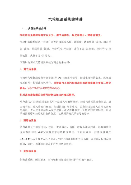
汽轮机油系统的精讲1 、典型油系统介绍汽机的油系统按功能可以分为:调节油部分,保安油部分,润滑油部分。
汽轮机的油系统是一套分厂完整的液压油系统,其组成:储油装置-油箱,动力单元-油泵,输送装置-管道,冷却单元-冷油器,净化单元-过滤器,控制单元-电调装置,执行单元-油动机。
下面以电调式汽轮机油系统为例分别来介绍:1 调节油系统电调型汽轮机通过电子调节器(即DEH)输出电信号,经过电液转换装置,改变成液压信号,控制油动机动作。
目前国内小型汽轮机用的电液转换器主要有三种分别是:VOITH,CPC,DDV(MOOG)。
作用是将接收到的电信号转换成相应的液压信号。
动力油(EH油)从注油泵出其中一路进入电液转换器,经过电液转换器变压后,成为调节油,进入错油门底部,控制错油门阀芯移动,改变动力油进入油动机活塞的油路,进而改变油动机活塞的位置。
油动机能够在一个特定的位置挺住,电调系统需要感知油动机目前的位置,这就需要有反馈信号的存在。
2 润滑油系统动力油来自主油泵出口,经过一射油器后,形成一股较低压力的油,这股油经过冷油器冷却至40℃(该温度下油的粘度最佳,工程实践中一般要求油温在40~45℃)后直接进入各个轴承,在转子轴颈和轴瓦之间形成一层油膜,起到润滑作用,同时,通过油将轴承处产生的热量带走。
3 保安油系统保安油系统,顾名思义,对汽轮机的起到安全保护作用的一股油。
保安油是由一股动力油在经过危机遮断装置后形成的。
保安油在汽轮机运行中,几乎不消耗油量,保安油压力与动力油一致。
只有当外部原因促使危机遮断装置动作,或者AST电磁阀动作,将保安油卸掉,保安油失压,使得汽轮机保安设备动作,起到关闭和保护汽轮机的作用。
例如汽轮机的主汽门液压缸上就接有保安油,当保安油失压后,主汽门会迅速关闭以切断汽轮机进汽。
2 、润滑油系统的组成系统主要由汽轮机主轴驱动的主油泵、冷油器、注油器、顶轴油系统、排烟系统、集装油箱(主油箱)、润滑油泵、事故油泵、密封油备用泵、滤网、电加热器、阀门、逆止门和各种监测仪表等构成。

VOITH电液转换器使用说明书型号:DSG-BXX113目录1.技术数据 (1)2.安全指示 (3)2.1 提示和标志的定义2.2 正确使用2.3 重要提示2.4 担保3.功能描述 (6)3.1 设计3.2 操作特点4.包装、储存、运输 (7)5.安装 (8)5.1 组装5.2 液压连接5.3 电器连接6. 试运行 (10)6.1 运行检测6.2 参数设定7.操作 (11)7.1 用手动旋钮操作7.2 用设定信号操作7.3 故障检修和排除8. 维护和检修 (13)9. 停机 (13)10. 具有接线图的外部管线图 (14)11. 附件 (15)1.技术数据:周围环境:储存温度-40 (90)工作环境温度-20 (85)保护IP65 to EN 60529适合于在工业空间内部安装电气数据:电压:24 VCD ±15%电流:大约0.7A(对DSG-B05…DSG-B10型)大约1A(对DSG-B30型)最大3A 时间t ‹ 1 Sec输入设置:0/4…20mA输入阻抗大约25欧姆,具有抑制电路。
液压参数:最小进口油压P in min: 1.5bar+最大输出P A max(对B05…B10型)5bar+最大输出油压P A max(对B30型)最大进口油压P in max :见表压力流体:不易燃烧的原油或压力油油粘度:根据DIN51519,ISO VG32…ISO VG48油温:+10℃ (70)油纯度:根据NAS1638为7级根据ISO4406为-/16/13级泄漏量:当进口油压P in=10bar 时≤3 l/min (对DSG-B05…DSG-B10 ) 当进口油压P in=40bar 时≤5 l/min(对DSG-B30)型号参数对照表:型号DSG-BXX113B05 B07 B10 B30 输出油压p A调整范围(bar)0...5 1...7 0...10 10 (30)最大进口油压P in (bar)40 40 40 40流量P→AQ1[l/min]当∆P═1bar24 24 23 24流量A→TQ2[l/min]当∆P═1bar30 30 28 30P A最大调整范围(bar)当设点为20mA时3...5 4...7 5...10 10 (13)P A最小调整范围(bar)当设点为4mA时0…1.50 (3)0.5 (3)1 (5)0 (2)0 (5)0 (5)0 (18)P A最小值调整范围处决于P A最大值的设定值.。
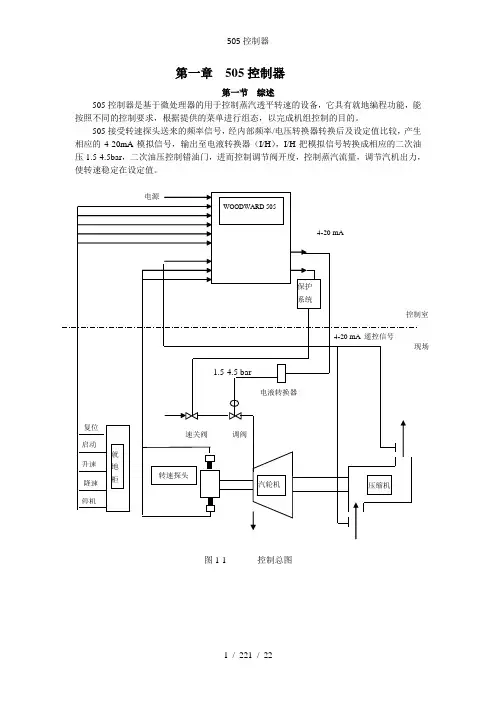
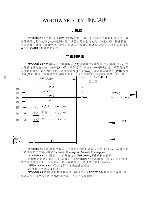
WOODWARD 505 操作说明一、概述WOODWARD 505 是美国WOODWARD 公司专门为控制汽轮机研制生产的以微处理器为基础的数字式转速调节器。
其特点是控制精度高、稳定性好、操作简便。
可根据每一台汽轮机的特性、参数,以及应用场合,对505进行组态。
其组态直接在WOODWARD 505面板上进行。
二.控制原理WOODWARD505接受二个转速探头(SE)监测的汽轮机转速信号(频率信号), 与内部转速设定值比较,经转速PID放大器作用后, 输出4-20mA操纵信号。
该信号送经电液转换器I/H (1742)转换成二次油压信号(1.5-4.5bar),二次油通过油动机(1910)控制转速稳定在设WOODWARD505也接受来自中控室或DCS的转速遥控信号(4-20mA),以使汽轮机转速满足工艺流程的需要(4mA对应xxxrpm,20mA对应xxxrpm)。
WOODWARD505输出一个实际转速信号(4-20mA)用作中控室指示。
汽轮机的启动、暖机、升/降速可以在WOODWARD505面板上完成。
此外汽机旁的电气操作间上,也设置了升速和降速按钮,也可以完成上述功能。
利用WOODWAR505可以进行汽轮机的超速试验。
505面板上会显现报警信号。
WOODWAR505监测到超速时发出一跳闸信号至ESD,ESD控制停机电磁阀, 泄掉速关油,快速关闭速关阀,切断汽源,以保证汽机安全。
三、操作规程馈板上调节螺钉,使油动机上指针指示hvmax。
2)使505输出4mA时。
调整电液转换器上电位器×O,使二次油压为1.5bar,再调错油门上调整螺钉,使油动机上指针指示O。
3)重复上述1)、2)过程,直至完全对应。
电液转换器是德国VOITH 公司的产品,能把4-20mA 模拟信号转换成符合要求的控制油压。
其调整进程见图10.2.汽机冲转1) 当开机条件具备时进行暖管, 2) 用启动装置开启速关阀。
3) 依次按WOODWARD505面板, 调阀逐渐打开, 汽机冲转并自动升至暖机转速(Idle Speed)进行暖 3.升速低速暖机结束, , 汽机将按设定的升速率自动升速至目标转速(RATED SPEED(,既。
有任何关于1/H型转换器的问题,根据转换器上的物品号和序列号,请联系V oith Turbo Gmbh & Co.KG公司电驱动系统的服务部。
V oith Turbo Gmbh & Co. KG邮政信箱15 55D-74555 Crailsheim总机:++49-7951/32-0传真:++49-7951/32-500电驱动系统产品服务部电话:++49-7951/32-470传真:++49-7951/32-605电子邮箱:****************V oith Turbo Gmbh & Co. KG供货地址Dept.ceV othstr.1D-74564 Crailsheim这个安装手册说明了从2003年9月以来交货的1/H转换器的技术条件。
在这之后交付产品所作的任何修改不写入本操作手册之内。
本安装手册版权所有未经许可,不得复制或翻译用作其他用途。
中国唯一代理:杭州怡林机电技术开发有限公司杭州市朝晖路182号国都发展大厦1幢19层H座邮编:310014电话:+86-571-85808865传真:+86-571-85808807内容1.技术数据2.安全信息2.1 标识符号说明2.2 使用范围2.3 重要说明2.4 授权3.功能描述3.1 构造设计3.2 操作特性4.包装、存储和运输5.安装5.1 装配5.2 液压连接5.3 电路连接6.试车6.1 测试运行6.2 参数设置7.操作7.1 用手动旋钮操作7.2 用设置信号操作7.3 问题解答和矫正措施8.维护和修理9.关闭10.接线略图11.附件1.技术数据环境条件:存储的环境温度-400C (900)环境温度-200C (850)保护IP 65 到EN 60529适合工业空气中的内部安装电路数据:电压24VDC±15%电源消耗接近0.7A 最大3A,对t<1秒给定值输入w=0/4…20mA 抑制电路输入电阻25欧姆液压数据:最小输入压力 1.5bar大于P A最大值最大输入压力见表压力流体矿物油或液压油(不易燃烧的要求)压力流体粘性ISO VG 32…ISO VG 48 到DIN 51519压力流体温度+100C (700)油纯度推荐纯度等级:NAS1638等级7 ISO4406等级-/16/13A AP A最小值的调节范围显示了第一条线涉及的最小的可调整的P A最大值。
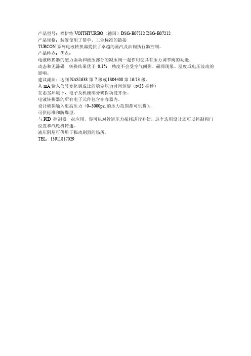
产品型号:福伊特VOITHTURBO(德国)DSG-B07112 DSG-B07212
产品规格:装置使用了简单、工业标准的链接
TURCON系列电液转换器提供了卓越的蒸汽及油阀执行器控制。
产品特点:优点:
电液转换器的磁力驱动和液压部分的减压阀一起作用使具有压力调节阀的功能。
动态和无滞磁转换结果优于0.1%精度不会受空气间隙、磁滞现象、温度或电压波动的影响。
建议滤油:达到NAS1638第7级或IS04408第16/13级。
从mA输入信号变化到成比的稳定压力时间短促(t<35毫秒)
在恶劣环境下,电子及机械部分确保功能齐全。
电液转换器的所有电子元件包含在容器内。
设计确保输入更高压力(0~3000psi的压力范围都可供货)。
可供标准和防爆型。
与 PID控制器一起应用,你可以对管道压力损耗进行补偿。
这个选用设计还可以控制阀门位置和汽轮机转速。
液压阻尼可供用于振动剧烈的场所。
TEL:139****7029。


-N型电液转换器型号:SVA9--N 价格:18000.00使用说明书SVA9-N 型电液转换器是专为汽轮机电液调速器开发的关键电-位移转换元件,它能把微弱的电气信号通过液压放大转换为具有相当大作用力的位移输出。
SVA9-N型电液转换器主要由动圈式力马达、控制滑阀及随动活塞三大部分组成,控制滑阀与随动活塞之间采用直接位置反馈,安装方式采用板式连接。
SVA9-N型电液转换器是SV9型电液转换器的改进型,是我公司应用户要求改制的抗污染型电液转换器,它针对电站行业对电液转换器工作须绝对可靠的要求,在SV9型基础上改进零部件材质、提高加工精度,加大动圈出力,并在进油口处增设可反吹冲洗、反复使用的高效过滤器。
与SV9相比,抗污染能力更强,工作更可靠,是更适合于电站行业应用的新一代电液转换器。
除电气参数不同外,在连接尺寸上它与SV9完全一致,可以方便地替代SV9而不需对调速器作任何改动。
SVA9-N型电液转换器结构精密,工作可靠,灵敏度高,动特性好,对油液洁净度要求较低,在NAS8级的油液中能长期稳定地工作,除此之外,还具有液压应急控制功能,只要通过一个二位四通阀把进出油口(P、T)换向或在进出油口(P、T)同时通入压力油,随动活塞就能立即下推到底。
一、工作原理SVA9-N型电液转换器的电气――位移转换部分采用了动圈力马达结构,液压放大部分采用了具有直接位置反馈的三通控制滑阀控制差动缸(随动活塞)的典型结构。
其工作原理如下:磁钢在气隙中造成固定磁场,当动圈绕组中有控制电流通过时,动圈在气隙磁场中受电磁力的作用,此电磁力克服弹簧力使动圈及控制滑阀产生与控制电流成正比例的位移。
压力油从P口进入,流经控制滑阀与随动活塞的上下可变节流口,由T口回油。
油源压力直接作用在随动活塞下腔,使之始终有一个向上的恒力,而上下节流口间的控制油压则作用在随动活塞上腔(被控腔),使之产生一个向下的推力。
随动活塞上腔面积设计成是下腔面积的两倍,因此当控制滑阀静止时,随动活塞自动地稳定在一个平衡位置,在这个位置上,上、下节流口的过流面积相等上腔控制油压刚好等于下腔油源压力的一半,使作用在随动活塞两端的液压推力相等。
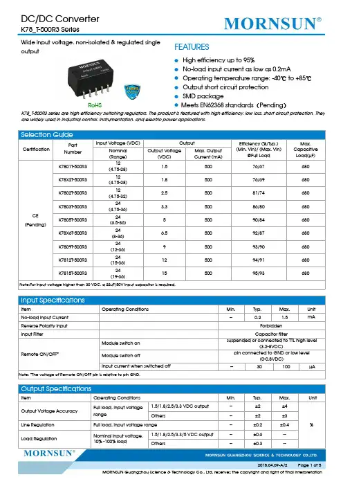
Wide input voltage,non-isolated ®ulated single outputRoHSFEATURES●High efficiency up to 95%●No-load input current as low as 0.2mA●Operating temperature range:-40℃to +85℃●Output short circuit protection ●SMD package●Meets EN62368standards (Pending )K78_T-500R3series are high efficiency switching regulators.The product is featured with high efficiency,low loss,short circuit protection.They are widely used in industrial control,instrumentation,and electric power applications.Selection GuideCertificationPart Number Input Voltage (VDC)OutputEfficiency (%/Typ.)(Min.Vin)/(Max.Vin)@Full LoadMax.Capacitive Load(µF)Nominal (Range)Output Voltage(VDC)Max.Output Current (mA)CE (Pending)K7801T-500R312(4.75-28) 1.550076/67680K78X2T-500R312(4.75-28) 1.850076/69680K7802T-500R312(4.75-32) 2.550081/74680K7803T-500R324(4.75-36) 3.350086/80680K7805T-500R324(6.5-36)550090/84680K78X6T-500R324(8-36) 6.550092/87680K7809T-500R324(12-36)950093/90680K7812T-500R324(15-36)1250094/91680K7815T-500R324(19-36)1550095/93680Note:For input voltage higher than 30VDC,a 22uF/50V input capacitor is required.Input SpecificationsItemOperating Conditions Min.Typ.Max.Unit No-load Input Current --0.21.5mAReverse Polarity Input ForbiddenInput FilterCapacitor filterRemote ON/OFF*Module switch onsuspended or connected to TTL high level(3.2-8VDC)Module switch offpin connected to GND or low level(0-0.8VDC)Input current when switched off--30100µANote:*The voltage of Remote ON/OFF pin is relative to pin GND.Output SpecificationsItemOperating Conditions Min.Typ.Max.UnitOutput Voltage Accuracy Full load,input voltage range1.5/1.8/2.5/3.3VDC o utput --±2±4%Others--±2±3Line Regulation Full load,input voltage range --±0.2±0.4Load RegulationNominal input voltage,10%-100%load1.5/1.8/2.5/3.3/5VDC o utput --±0.6--Others--±0.3--Ripple &Noise*20MHz bandwidth,nominal input voltage1.5/1.8/2.5/3.3VDC output,20%-100%load --2050mVp-p Others,10%-100%load--2050Temperature Coefficient Operating temperature -40℃to +85℃----±0.03%/℃Transient response deviation Nominal input voltage,25%load step change --50200mV Transient recovery time --0.21msOutput short circuit protection Nominal input voltage Continuous,self-recoveryVadjinput voltage range--±10--%VoNote:*1.Ripple and noise tested with “parallel cable”method,please refer to DC-DC Converter Application Notes for specific operation methods;*2.With the load lower than 20%,the maximum ripple and noise of 1.5/1.8/2.5/3.3V output products will be 100mVp-p;With the load lower than 10%,5V/6.5V/9V/12V/15V output products will be 150mVp-p.General SpecificationsItemOperating Conditions Min.Typ.Max.单位Operating Temperature see Fig.1-40--+85℃Storage Temperature -55--+125Storage HumidityNon-condensing 5--95%RHReflow Soldering TemperaturePeak temp.≤245℃,maximum durationtime ≤60s at 217℃.For actual application,please refer to IPC/JEDEC J-STD-020D.1.Switching Frequency Full load,nominal input voltageK7801T-500R3--370--KHz Others--700--MTBFMIL-HDBK-217F@25℃2000----K hoursPhysical SpecificationsCasing Material Black flame-retardant and heat-resistant plastic (UL94V-0)Package Dimensions 15.24*11.40*8.25mm Weight1.5g (Typ.)Cooling MethodFree air convectionEMC SpecificationsEMICE CISPR32/EN55032CLASS B (see Fig.4-②for recommended circuit)RE CISPR32/EN55032CLASS B (see Fig.4-②for recommended circuit)EMSESD IEC/EN 61000-4-2Contact ±4KV perf.Criteria B RSIEC/EN 61000-4-310V/mperf.Criteria A EFT IEC/EN 61000-4-4±1KV (see Fig.4-①for recommended circuit)perf.Criteria B Surge IEC/EN 61000-4-5line to line ±1KV (see Fig.4-①for recommended circuit)perf.Criteria B CSIEC/EN 61000-4-63Vr.m.sperf.Criteria AProduct Characteristic CurveO u t p u t P o w e r P e r c e n t a g e (%)020406080100120-404085120Safe Operating AreaOperating Temperature ( ℃)71T emperature Derating CurveFig.1Design Reference1.Typical application circuitFig.2Typical application circuitPartNumberC1(ceramiccapacitor)C2(ceramiccapacitor)Ra1/Ra2(Vadjresistance) K7801T-500R310µF/50V22µF/10VRefer to Vadjresistancecalculation K78X2T-500R322µF/10VK7802T-500R322µF/10VK7803T-500R322µF/10VK7805T-500R322µF/16VK78X6T-500R322µF/16VK7809T-500R322µF/25VK7812T-500R322µF/25VK7815T-500R322µF/25VSheet1Note:1.C1and C2are required and should be connected close to the pin terminal of the module.2.The capacitance of C1and C2refer to Sheet1,it can be increased properly if required,and tantalum or low ESR electrolytic capacitors may also suffice.3.Cannot be used in parallel for output and hot swap.To reduce the output ripple furtherly,it is suggested to connect a“LC”filter at the output terminal,and recommended value of L is10µH-47µH.Fig.3“LC”filter application circuit2.EMC solution-recommended circuitDC/DCVinLDM2②C0LDM1MOVFUSE①C5GN D++VoGN DC2C1Note:Part ①in the Fig.4is for EMS test,part ②is for EMI filtering;parts ①and ②can be added based on actual requirement.FUSEMOV LDM1C0C1/C2C5LDM2Selected based on the actual input current from the customerS20K3082µH680µF /50VRefer to Sheet 14.7µF /50V12µH3.Application of Vadj and calculation of Vadj resistanceR 2R 1R 3V ref R a2Vo’R 2R 1R 3Vref R a1VadjVo’Vadj up Vadj downFig.5Applied circuits of Vadj (Part in broken line is the interior of models)Calculation formula of Vadj resistance:up: a=VrefVo’-Vref R 1R =a2aR 2R -a 2-R 3down: a=VrefVo’-VrefR 2R =a1aR 1R -a1-R 3R a1、R a2is Vadj resistance ,a is a self-defined parameter,with no real meaning.Vo’for the actual needs of the up or down regulated voltageVout(V)R1(K Ω)R2(K Ω)R3(K Ω)Vref(V)1.57.57.5150.751.835.726.291000.7652.52711.858510.7653.3339.9470.76557513.5750.7656.57510510.765951 4.7270.7651275 5.1270.76515824.423270.765Note:The 1.5VDC output model only support Vadj up,do not support Vadj down.4.For more information please find the application notes on Dimensions and Recommended LayoutNotes:1.Packing information please refer to Product Packing Information which can be downloaded from .TubePacking bag number:58210057,Roll packing bag number:58210058.2.The max.capacitive load should be tested within the input voltage range and under full load conditions;3.Unless otherwise specified,data in this datasheet should be tested under the conditions of Ta=25℃,humidity<75%RH when inputtingnominal voltage and outputting rated load;4.All index testing methods in this datasheet are based on our Company’s corporate standards;5.The performance indexes of the product models listed in this manual are as above,but some indexes of non-standard model productswill exceed the above-mentioned requirements,and please directly contact with our technician for specific information;6.Products are related to laws and regulations:see"Features"and"EMC";7.Our products shall be classified according to ISO14001and related environmental laws and regulations,and shall be handled byqualified units.MORNSUN Guangzhou Science&Technology Co.,Ltd.Address:No.5,Kehui St.1,Kehui Development Center,Science Ave.,Guangzhou Science City,Luogang District,Guangzhou,P.R.China Tel:86-20-38601850-8801Fax:86-20-38601272E-mail:***************。
S V A9-N型电液转换器
型号:SVA9--N
价格:18000.00
使用说明书
SVA9-N型电液转换器是专为汽轮机电液调速器开发的关键电-位移转换元件,它能把微弱的电气信号通过液压放大转换为具有相当大作用力的位移输出。
SVA9-N型电液转换器主要由动圈式力马达、控制滑阀及随动活塞三大部分组成,控制滑阀与随动活塞之间采用直接位置反馈,安装方式采用板式连接。
SVA9-N型电液转换器是SV9型电液转换器的改进型,是我公司应用户要求改制的抗污染型电液转换器,它针对电站行业对电液转换器工作须绝对可靠的要求,在SV9型基础上改进零部件材质、提高加工精度,加大动圈出力,并在进油口处增设可反吹冲洗、反复使用的高效过滤器。
与SV9相比,抗污染能力更强,工作更可靠,是更适合于电站行业应用的新一代电液转换器。
除电气参数不同外,在连接尺寸上它与SV9完全一致,可以方便地替代SV9而不需对调速器作任何改动。
SVA9-N型电液转换器结构精密,工作可靠,灵敏度高,动特性好,对油液洁净度要求较低,在NAS8级的油液中能长期稳定地工作,除此之外,还具有液压应急控制功能,只要通过一个二位四通阀把进出油口(P、T)换向或在进出油口(P、T)同时通入压力油,随动活塞就能立即下推到底。
一、工作原理
SVA9-N型电液转换器的电气――位移转换部分采用了动圈力马达结构,液压放大部分采用了具有直接位置反馈的三通控制滑阀控制差动缸(随动活塞)的典型结构。
其工作原理如下:
磁钢在气隙中造成固定磁场,当动圈绕组中有控制电流通过时,动圈在气隙磁场中受电磁力的作用,此电磁力克服弹簧力。
I/H Converter Type DSG-B03212 Type DSG-B07212Instruction ManualVersion 1.0Should you have any questions concerning the I/H converter, please contact the Service Department of the product group Electronic Drive Systems, Voith Turbo GmbH & Co. KG, Crailsheim, indicatingarticle number and serial number of the I/H converter.Voith Turbo GmbH & Co. KGP.O. Box 15 55D-74555 CrailsheimSwitchboard:++49 – 7951 / 32 - 0Fax:++49 – 7951 / 32 – 500Service department of the product groupElectronic Drive SystemsDirect dial:++49 – 7951 / 32 - 470Direct fax: ++49 – 7951 / 32 - 605E-mail: turcon@Address for goods supplied:Voith Turbo GmbH & Co. KGDept. ceVoithstr. 1D-74564 CrailsheimThis instruction manual describes the technical condition of theI/H converter on delivery from May 2003.Any modifications following the delivery are not considered in this operating manual.Ó Voith Turbo GmbH & Co. KG 2003This instruction manual is protected by copyright.It may not be reproduced or translated in any form or by anymeans (mechanical or electronic) or submitted tothird parties, without the publisher’s written approval.Issued:03-05Order No.: 3.626- 018861 enVersion: 1.00Printed in GermanyContents1.Technical data2.Safety Information2.1Definition of notes and symbols2.2Proper use2.3Important notes2.4Warranty3.Functional Description3.1Mechanical design3.2Operating characteristics4.Packing, Storage and Transport5.Installation5.1Mounting5.2Hydraulic connection5.3Electric connection6. Commissioning6.1Test run6.2Parameter setting7. Operation7.1 Operation with manual operation knob7.2 Operation wit set signal7.3 Trouble shooting and remedial action8.Maintenance and Repair9.Shutdown10.Outline drawing with Wiring Diagram11.Annex1.Technical DataAmbient conditions:Ambient temperature for storage-40 °C ... +90 °CAmbient temperature:- Normal operation-20 °C ... +85 °C- Potentially explosive atmos.-20 °C ... +60 °CExplosion protection EEx d IICTemperature class T4, at Ta = -20 °C ... +60 °CDevice group IICategory2GProtection IP 65 to EN 60529suitable for internal installation in industrial airElectric data:Supply voltage24 VDC ± 10%Power consumption approx. 0.7 Amax. 3 A, for t < 1 sec Setpoint input w = 0/4...20 mAinput resistor 25 Ohmwith suppressor circuitHydraulic data:Input pressure P in min 1.5 bar more than P A max Input pressure P in max see tablePressure fluid mineral oil or hydraulic oil(hardly combustible fluids onrequest)Viscosity pressure fluid ISO VG 32... ISO VG 48 toDIN 51519Temperature pressure fluid:+10 °C...+60 °COil purity recommended purity class:To NAS1638 class 7To ISO4406 class -/16/13 Leakage£ 5 l/minDSG-BXX212TypeB03...B07... Output pressure regulating rangeP A[bar]0..30..7 Input pressureP(max) [bar]4040Flow rate line P ® AQ1[l/min]at D P = 1 bar1717Flow rate line A ® TQ2[l/min]at D P = 1 bar1818Regulating range approx.P A max [bar]at setpoint w = 20 mA1..3 5..7Regulating range approx.P A min [bar] at setpoint w = 4 mA 0..0.80..21..31.5..5The regulating range of P A min depends on the set pressure P A max.The regulating range of P A min indicated in the first line refers to the minimum adjustable pressure P A max .Mechanical data:Dimensions, fitting see chapter 10Hydraulic connection see chapter 10Mounting position see chapter 10Sealing material FPMWeight approx. 12 kg2.Safety Information2.1Definition of notes and symbolsDanger !This symbol signals an imminent danger to the life andhealth of individuals.If this note is not observed, injury to health and even mostserious injuries may be the consequence.Warning !This symbol signals a harmful situation.If this note is not observed, the product may be damaged.Note !This symbol refers to proper handling of the product. It does not refer toor indicate a dangerous situation.2.2Proper useThe I/H converter serves to transform an electric set signalinto a related hydraulic output pressure reduced to feed-in pressure. Thisallows, for example, adjusting control pistons at hydraulic cylinders whichare used to position the valves of steam turbines.The I/H converter is suitable for usage in potentially explosiveatmospheres according to the explosion protection mentioned inchapter 1.2.3Important notesThe following notes refer to the entire instruction manual and have to beobserved in addition to the individual notes.Accident prevention·In any case observe the relevant standards and regulations when connecting an I/H converter in ex-design.·Improper use may cause operating agent under pressure to leak at the sealing surfaces. There is a risk of fire around hot components.·Isolate the hydraulic supply prior to working on the I/H converter.·Failure of electric power or disturbance of the control electronics integrated in the I/H converter may cause strong variations of theoutput pressure when operating the I/H converter. Thus e.g. thepiston rod of a hydraulic cylinder may move uncontrolled, causingdanger to individuals or equipment.·During operation, the outer surfaces of the I/H converter may heat up due to the pressure fluid. Contact may cause skin burns. Make sure to cool down the I/H converter prior to working on it.·Electrical components are installed in the I/H converter. These components can be destroyed by e.g. welding in its surrounding.Therefore make sure to disconnect all electric connections prior to electrical weldings in the surrounding of the I/H converter.Environment protection·During mounting, dismounting or improper use of the I/H converter pressure fluid may leak out. Operating agent reaching the sewage system or the open soil, causes severe environmental damages.Leaking pressure fluid has to be collected and deposited inaccordance with the national legal regulations.Instruction manual·The instruction manual contains important information for proper handling of the I/H converter. Prior to installation and commissioning of the I/H converter, read the manual carefully and make sure it iscompletely understood.·Keep this manual in a location convenient to the operating staff.·In addition to this operating manual: Have the relevant regulations for prevention of accidents and environmental protection available and observe these.Staff qualification·Only trained and instructed staff is allowed to perform any work on the I/H converter. This personnel has to be trained and authorized tomount I/H converters professionally.·Installation, commissioning and operation have to be performed by an electronic expert with experiences and knowledge in explosionprotection.Constructional modifications·Mounting and constructional modifications are not permitted.·The screwing of the cable inlet is secured against distortion. Do not distort or loosen the screwing.2.4WarrantyThe terms and conditions mentioned in the General Conditionsof Sale of Voith Turbo GmbH & Co. KG, Crailsheim, are applicable.Warranty claims are excluded, if these are due to one or several of thefollowing causes:·Improper transportation, storage, mounting, set-up, commissioning and operation of the I/H converter.·Not observing the safety instructions and guidelines included in this instruction manual.·Use of spare parts not approved byVoith Turbo GmbH & Co. KG, Crailsheim.Repair works on the I/H converter are to be performed or approved byVoith Turbo GmbH & Co. KG, Crailsheim.3.Function3.1DesignFig. 3.1.11 – Control magnet VRM P- Input pressure2 – Tappet for power transmission P A- Output signal pressure3 - Potentiometer X0 und X14 – Manual operation knob T1- Tank return line5 – Electric connection T2- Tank return line int. leakage6 – Control housing F Mag- Magnetic force7 – Control piston F Hyd- Hydraulic force8 - Cover F Fed- Spring force9 - Control spring3.2 Operatingcharacteristics(see fig. 3.1.1)A set signal w = 0/4...20 mA generates a magnetic force F Mag in theVRM, the limits of which can be adjusted by means of the X0 and X1potentiometers and which is then transmitted onto the control piston viatappet.The hydraulic force F Hyd being proportional to the output signal pressureP A acts against this force.In the case of the two forces being equal, the control piston is positionedin the “hydraulic center” as shown in fig. 3.1.1 and the output signalpressure P A corresponds to the set signal. In the “hydraulic center“position the control piston performs minimum oscillating movements inthe area of the guiding edges P®P A and P A®T , in order to keep theoutput pressure P A on the value set by F Mag.When increasing the set signal and thus F Mag from this condition, thecontrol piston position changes and thus connects the output pressure P Ato the feed pressure P in and blocks P A towards the tank return line T1.Now the pressure P A will increase until the control piston returns to the”hydraulic center“ and P A corresponds to the new set signal.The spring force F Fed of the control spring generates a force-offset inorder to guarantee the I/H converter function for output pressures ofapprox. 0 bar, too.The internal leakage is fed back via tank return line T2.Function of manual operation knobThe control magnet of the I/H converter is provided with a manualoperation knob, by means of which an adjustable spring force can be setinstead of the magnetic force F Mag . This spring force affects the controlpiston via magnet armature and tappet. The hydraulic force F Hyd , beingproportional to the output signal pressure P A also acts against this springforce here. Thus adjustment of output pressure is possible withoutelectric connection.4.Packing, Storage and TransportPackingThe I/H converter is delivered in a special packing.The openings for the hydraulic connections are sealed with plugs toprevent penetration of impurities and humidity.Storage and preservingThe outer surfaces of the I/H converter are protected by means of apreserving surface coat.The internal parts are preserved by oil.Within Europe the anticorrosion protection is sufficient for approx. 8months in industrial air, presuming storage of the I/H converter in a drylocation.In case the I/H converter is supposed to be stored for a longer period oftime, special precautions will have to be taken.In each specific case, these precautions have to be agreed withVoith Turbo GmbH & Co, KG, Crailsheim.The storage ambient conditions have to be within the limits as indicatedin chapter 1.TransportImproper transport may cause personal injuries and damages toproperty.Pack the I/H converter in a way that prevents housing damages duringtransport. In particular make sure that no compulsive forces affect theelectric cable fitting and the electric feed in cable are not kinked ordamaged. Do not hold the I/H converter at the electric feed in cable fortransport.5.Installation·Improper installation of the I/H converter may cause malfunctions and premature failure of the operation of the I/H converter.·Cleanliness is imperative during installation an connection. Prevent that any impurities ( dust, metal chips etc.) can get into the I/Hconverter or pipe system which may cause damage to the I/Hconverter.Cover and protect the I/H converter and in particular the electric linesduring construction time.5.1MountingPerform any work on the I/H converter only when it is in deenergizedcondition and with switched off oil supply system.Protect oil and power supply against unintentional switching-on duringmounting.Install the I/H converter in accordance with the permissible installationposition as shown in chapter 10.Recommended fastening bolts:2 pieces hexagonal screws M10, strength category 8.8.tightening torque MA=35 Nm, thread slightly oiled.Select screw length according to mounting situation.connection5.2 HydraulicThe hydraulic connection on the I/H converter is made by means ofconnection bores at its bottom. The connection flange is sealed witho-rings. Please refer to chapter 10 for position and dimensions of theconnections.Surface roughness of connecting flange:Ra = 1.6 m m, Rmax = 6.3 m mOnly pressure-less return of the operating medium through the return lineT2 to the tank, ensures proper work of the I/H converter.In practise the tank lines for the connections T1 and T2 are joinedtogether and laid downgrade towards the tank in one common pipe line.Requirements to this pipe line:Nominal size 20 mm or bigger for I/H converters with an output pressureup to 10 bar.Nominal size 30 mm or bigger for I/H converters with an output pressureof more than 10 bar.Observe the correct pressure range when selecting pipes, hoses,screwings and flanges.Immediately replace damaged pipes and hose lines.When assembling the pipe lines, ensure that it is fastened to fixedstructures, free from vibration and not to moving equipment. Temperaturevariations of the piping (thus alterations in length) must not applyconstraining forces to the I/H converter.Clean pipe lines from dirt, cinder, sand, chips etc. prior to installation.Pickle or flush welded pipes.Clean and flush carefully all pipe and hose lines prior to attaching theI/H converter.=> For flushing, a flushing plate (Art. No. 43.8565.10) is available.See chapter 11.=> To connect the I/H converter to the piping system an adapter (Art. no.43.9300.11) is available. See chapter 11.·Residual oil may leak when removing the plug (max. 0,1 l). Collect the oil in a suitable container and deposit it properly.·Do not use fibrous or hardening sealing compounds, such as e.g.hemp or mastic to seal the connections and screwings.5.3Electric connectionThe electric system has to be connected in accordance with electricalengineering standards and legal regulations of the manufacturingcountry. The works have to be performed by an electric specialist withexperience and knowledge in explosion protection.When connecting the I/H converter within the explosion hazardous area ,the electric feed in line have to be connected in housings according toprotection type EN 50014, section 1.2.When connecting customer´s lines, avoid parallel run of the I/H converterlines with the lines of current converter assemblies.The customer`s signals and supply lines running to the I/H convertermust be screened.Please refer to chapter 10 for the wiring diagram.missioningThe I/H converter was adjusted and tested at Voith Turbo’s works bymeans of the potentiometers X0 and X1. The test result is documented inan attached test certificate.The potentiometers are provided with a protective cap to avoidunintentional maladjustment and impurities.6.1Test runMake sure that pipe lines and hydraulic system are cleaned prior toperforming a test run. The operating fluid has to be in accordance withthe purity class as indicated in chapter 1. Do not flush or clean thepressure fluid with the I/H converter being hydraulically connected.Operation of the I/H converter with contaminated pressure fluid is notpermitted, the I/H converter may be damaged.·Check the line mounting, connection and flow direction to and on the I/H converter.·Check the electric connection.·Switch on the 24 VDC power supply.·Switch on the oil supply and check input pressure.The minimum input pressure has to be 1.5 bar more than the maximumoutput pressure required at 20 mA.·Set the signal w = 0/4.. 20mA and check output pressure.During the test run, check all hydraulic connections for leakages. Incase of leakage, immediately switch off the hydraulic supply andeliminate leakages.6.2Parameter settingDue to unintentional maladjustment of the parameters or changedoperating conditions, new setting of one or both parameters may becomenecessary.We recommend to document adjustment of the parameters as well as theset values.The parameters are adjusted by means of potentiometers X0 and X1.Please refer to chapter 10 for the position of the potentiometers.Potentiometer effects:X0-With help of potentiometer X0 the minimum output pressureP A min is adjusted at a setpoint of 0 mA or 4 mA.Pressure increase by turning the potentiometer clockwise.X1-With help of potentiometer X1 the maximum output pressureP A max is adjusted at a setpoint of 20 mA.Pressure increase by turning the potentiometer clockwiseX1 should be adjusted before X0.The X1- adjustment influences the adjustment of X0.Manufacturer-provided adjustments:At the works, the I/H converter has been adjusted as indicated in theorder.7.Operation7.1 Operation with manual knobOperation with manually controlled rotary knob is possible without electricenergy.On operation with manually actuated rotary knob, uncontrolled strokemovements of the hydraulic components controlled by the I/H converteroutput might occur due to the increase in the output signal pressure.Manual operation is only possible when the circlip is removed from themanual operation knob.On completion of operation with manual operation knob, move themanual operation knob in its final position by turning it counter clockwiseand pushing in the circlip to its final position.·Remove the circlip.·Slowly turn the manual operation knob clockwise and observe the output pressure.Effective direction: Output pressure increase by clockwise rotation.7.2Operation with set signalWhen the supply voltage is switched on, the output signal pressure canbe adjusted continuously by the set signal 0/4...20 mA within the limitsset by the potentiometers X0 und X1.7.3Trouble shooting and remedial actionPrior to all works, make sure that the I/H converter was commissionedaccording to chapters 5 and 6.Malfunction: Pressure variationsThe output signal pressure P A may vary now and then orperiodically with low or high frequency and amplitude.Cause: 1. air inclusions in the hydraulic component2. low or considerably varying input pressure.3. dirt particles in the hydraulic component4. pressure on return lineRemedy: 1.On first commissioning air inclusions in the VRM may causepressure variations. Due to periodic setpoint changes(approx. 0.5 Hz) of approx. +/- 6 mA, the air will escape outof the VRM after some minutes causing the hydraulicdamping to become effective.2. Under load and in particular in case of higher outputsignal pressure, a lower input pressure may lead topressure variations.Increase and / or stabilize the input pressure by takingappropriate measures (e.g. accumulator). See also chapter1.3. Contaminated pressure fluid results in increased friction atthe control piston, thus causing hysteresis and pressurevariations.Open hydraulic component and clean the inner elements. Incase of damaged surfaces and guiding edges replace theI/H converter.4. The dimensions of the return line have to be sufficient.In case of additional consumers of the output pressureconnected to this line, make sure they do not create anypressure in the return line. See also chapter 5.2.Malfunction:Output pressure PA ® 0 bar or ® P (input pressure)Due to a defective control valve VRM or blockage of thecontrol piston the output pressure may fall to 0 bar orincrease to the input pressure.Remedy:The function of the hydraulic component can be checked using the manually controlled knob with the supply voltage beingswitched off. See chapter 7.1.If the output pressure cannot be adjusted manually, the controlpiston, e.g., may be blocked by particles.Open hydraulic component and clean inner parts.If the surfaces and guiding lines are damaged, exchangethe I/H converter.Should output pressure adjustment be possible with manualoperation knob, but not with the control magnet, the controlmagnet VRM is defective.Repairs on the control magnet VRM are not allowed, otherwiseexplosion protection is no longer guaranteed.Replace any defective I/H converter completely.8.Maintenance and RepairFor a trouble-free and reliable operation of the I/H converter, it isnecessary to perform inspection, maintenance and repair work incertain intervals.Routine inspectionCheck the pipes, screw connections and connections on theI/H converter for leakage, impurities and damage.Eliminate any leakage, impurity and damage noticed, if required, duringappropriate operating modes.Monitor the control behavior of the I/H converter for any changes.Analyse and eliminate the causes, if required, during appropriateoperating modes.Inspection after approx. 740 operating hours / max. 1 monthTake an oil sample from the oil tank and analyse it for solid andsuspended matters, water content, shadings and air bubbles.Analyse oil purity of the oil sample. Clean or exchange the oil, ifrequired, in an appropriate operating mode.Inspection after approx. 8000 operating hours / max. 1 yearTake an oil sample from the oil tank and analyse it chemically.If required, clean or change the oil during an appropriate operating mode.Check and retighten, if necessary, the electric connections of the I/Hconverter.9.ShutdownIf the I/H converter is switched off for reasons of repair, inspection orunit shutdown, switch off the oil supply system and relieve all pressurereservoirs, if effective. Switch off the 24 VDC supply voltage andremove the lines as well as piping and hose connections. Doing so, anconsiderable oil quantity may leak out. Collect the oil in a suitablecontainer and deposit it properly. Close all holes. Now clean and packthe I/H converter.DisposalIn the event of disposal of the I/H converter, observe the local applicableregulations regarding the environmental protection. The I/H converteressentially contains steel, copper, synthetic materials, electroniccomponents and residual oil.10.Outline and Wiring Diagram11.AnnexFlushing plate43.8565.10Adapter plate43.9300.11。
VOITH电液转换器使用说明书型号:DSG-BXX113翻译:研发中心孙云超目录1.技术数据 (1)2.安全指示 (3)2.1 提示和标志的定义2.2 正确使用2.3 重要提示2.4 担保3.功能描述 (6)3.1 设计3.2 操作特点4.包装、储存、运输 (7)5.安装 (8)5.1 组装5.2 液压连接5.3 电器连接6. 试运行 (10)6.1 运行检测6.2 参数设定7.操作 (11)7.1 用手动旋钮操作7.2 用设定信号操作7.3 故障检修和排除8. 维护和检修 (13)9. 停机 (13)10. 具有接线图的外部管线图 (14)11. 附件 (15)1.技术数据:周围环境:储存温度-40 (90)工作环境温度-20 (85)保护IP65 to EN 60529适合于在工业空间内部安装电气数据:电压:24 VCD ±15%电流:大约0.7A(对DSG-B05…DSG-B10型)大约1A(对DSG-B30型)最大3A 时间t ‹ 1 Sec输入设置:0/4…20mA输入阻抗大约25欧姆,具有抑制电路。
液压参数:最小进口油压P in min: 1.5bar+最大输出P A max(对B05…B10型)5bar+最大输出油压P A max(对B30型)最大进口油压P in max :见表压力流体:不易燃烧的原油或压力油油粘度:根据DIN51519,ISO VG32…ISO VG48油温:+10℃ (70)油纯度:根据NAS1638为7级根据ISO4406为-/16/13级泄漏量:当进口油压P in=10bar 时≤3 l/min (对DSG-B05…DSG-B10 ) 当进口油压P in=40bar 时≤5 l/min(对DSG-B30)型号DSG-BXX113B05 B07 B10 B30 输出油压p A调整范围(bar)0...5 1...7 0...10 10 (30)最大进口油压P in (bar)40 40 40 40流量P→AQ1[l/min]当∆P═1bar24 24 23 24流量A→TQ2[l/min]当∆P═1bar30 30 28 30P A最大调整范围(bar)当设点为20mA时3...5 4...7 5...10 10 (13)P A最小调整范围(bar)当设点为4mA时0…1.50 (3)0.5 (3)1 (5)0 (2)0 (5)0 (5)0 (18)P A最小值调整范围处决于P A最大值的设定值.。
目录1.技术数据2.安全信息2.1 符号的意义2.2使用方法2.3重要标识2.4保修3.功能描述3.1机械构造3.2运行特性4.包装、储存和运输5.安装5.1安装5.2液压通讯5.3电通讯6.试运行6.1运行测试6.2参数设定7.操作7.1手动按钮操作7.2信号设置操作8.维护和修理9关闭10.主要线路图11.附录1.技术数据环境条件:保存温度-40℃ (90)环境温度:-正常操作-20℃ (85)-气体爆炸危险-20℃ (60)防爆等级EEx d IIC温度等级T4,在Ta=-20℃ (60)设备组别II类别2G防护等级IP 65 to EN 60529适合在工业内部环境中安装电气数据供电电压24VDC±10%能耗0.7A左右最大一秒内3A输入设置W=0/4…20mA带抑流器时输入电阻25 Ohm液压数据:最小输入压力比输出压力信号上限值大1.5bar最大输入压力见表格液压矿物油或液体油(要求不可燃液体)压力流体粘度ISO VG 32…ISO VG 48 to DIN 51519压力流体温度+10℃ (60)油品纯度纯度等级要求NAS1638 7级ISO4406 class-/16/13漏量≤5l/min ——————————————————————————————————类型DSG-BXX212B03…B07…——————————————————————————————————输出压力信号范围P[bar] 0..3 0..7A —————————————————————————————————— [bar] 40 40 输入压力P(max)——————————————————————————————————流量速率线 P→A 17 17 (l/min) Q1 [l/min]△P=1 bar时——————————————————————————————————流量速率线 A→T 18 18 (l/min) Q1 [l/min]△P=1 bar时——————————————————————————————————大致调节范围 1..3 5..7Pmax [bar]A设定为w=20mA时——————————————————————————————————大致调节范围0..0.8 1..3Pmin [bar]A设定为w=4mA时0..2 1.5..5压力下限值取决于压力上限值的设置压力下限值在最小值的第一条线里显示出来机械数据:尺寸,配置见第10章液压通讯见第10章装置位置见第10章密封材料 FPM重量大约12kg2.安全信息2.1符号意义危险!这个符号表明对人的生命安全有重大威胁。
voith电液转换器原理
摘要:
1.Voith 电液转换器的概述
2.Voith 电液转换器的工作原理
3.Voith 电液转换器的应用领域
4.Voith 电液转换器的优势与局限性
正文:
【概述】
Voith 电液转换器,是一种将电气信号转换为液压信号的装置。
它的核心部件是电气- 液压转换器,这种转换器通过控制电气信号,实现对液压系统的精确控制。
Voith 电液转换器在工业领域中被广泛应用,例如在钢铁、汽车制造、船舶等重工业领域,以及一些大型工程项目中。
【工作原理】
Voith 电液转换器的工作原理主要分为两部分:电气信号的输入和液压信号的输出。
首先,电气信号输入部分,Voith 电液转换器接收来自控制系统的电气信号。
这些信号经过转换器内部的电路处理,转换为转换器可以识别和执行的信号。
然后,液压信号输出部分,转换器根据输入的电气信号,通过内部的液压元件,产生相应的液压信号。
这个液压信号可以被转换器连接的液压系统识别和执行。
【应用领域】
Voith 电液转换器的应用领域非常广泛,几乎涵盖了所有需要精确控制液压系统的工业领域。
例如,在钢铁工业中,Voith 电液转换器可以用于控制轧钢机的压力和速度;在汽车制造中,它可以用于控制机器人手臂的运动;在船舶中,它可以用于控制舵机的转动等等。
【优势与局限性】
Voith 电液转换器的主要优势在于,它能够将电气信号精确地转换为液压信号,从而实现对液压系统的精确控制。
这使得Voith 电液转换器在需要高精度、高效率的工业领域中具有广泛的应用前景。
然而,Voith 电液转换器也存在一些局限性。
第 3 章. 参数设置,功能选择与运行操作引言本章将针对操作员画面的参数和运行进展具体的介绍和讲解。
T80掌握器全部的显示和操作都将在此完成。
操作员画面主要分以下四个画面,参数设置1,参数设置2,电调试验,电调主控. 其中参数设置1,参数设置2,电调试验三个画面的数据须工程师权限才允许操作修改.如图3-1,2,3,4.图3-1. 参数设置1该页主要包括机组额定参数设置,伺服参数设置,一次调频参数设置以及临界区和暖机点的设置。
留意——正确操作在修改参数设置 1和参数设置 2画面上的任何参数之前,请先按下“允许修改”按钮,在修改完数据后准时按灭“允许修改”按钮。
在“允许修改”按钮灯熄灭期间,修改参数无效。
图3-2. 参数设置2图3-3. 电调试验画面图3-4. 电调主控画面菜单栏状态栏汽机信息------掌握模式切换栏页面切换按钮--图3-5. 画面根本构成解析一.参数设置与功能选择(1)机组根底额定参数设定机组额定参数设定位于参数设置1 画面左侧,在修改前请留意先按下允许修改按钮,修改完后准时按灭允许修改按钮。
机组类型:可以左键点击选择纯凝机组或者背压机组。
参数设定说明如下:额定转速:默认3000 转。
对格外规机组,可以设定0-12023 之间的任何转速。
测速齿数:默认60 齿。
可在0-500 间设定。
额定主汽压力:可在0-100MPa 间设定。
额定功率值:可在0-100MW 间设定。
额定排汽压力:可在0-100MPa 间设定〔。
背压机组有此参数〕转速通道数目:1-3 可选。
最大升速率:默认800rpm 。
可选0-5000rpm。
临界区升速率:默认400rpm 。
可选0-5000rpm。
电子打闸转速值:默认3300rpm。
可选0-12023rpm。
旁路启动功能:需要旁路启动功能打勾。
没有无需勾选。
旁路切换转速点:默认2700rpm。
可选0-12023rpm。
〔无旁路功能无此项〕就地升速功能:需要就地盘起机的请勾选此项。