fluke 317 319钳形电流表的超差校准方法
- 格式:doc
- 大小:314.50 KB
- 文档页数:2

钳形电流表校准装置校准规范1范围本规范适用于直流或交流频率为(45~400)Hz、电流(0.1~2000)A,具有交流电流或直流电流或兼具交直流电流输出功能的钳形电流表校准装置的校准。
2引用文件本规范引用了下列文件:JJF 1075-2015钳形电流表校准规范凡是注日期的引用文件,仅注日期的版本适用于本规范。
凡是不注日期的引用文件,其最新版本(包括所有的修改单)适用于本规范。
3概述钳形电流表校准装置是一种用于校准交直流钳形电流表及相关测量功能的装置,可直接输出大范围的交直流电流,直接对交直流钳形电流表进行校准。
电流输出准确度和稳定度高,能够校准5.0级及以上准确度等级的钳形电流表。
4计量特性电流输出范围:(0.1~2000)A电流工作频率:直流或交流频率(45~400)Hz表1 钳形电流表校准装置的计量性能注:由于校准不判断合格与否,故上述计量特性要求仅供参考。
5 校准条件5.1环境条件5.1.1 环境温度:(20±5)℃;5.1.2 相对湿度:(55±20)%;5.1.3 电源电压:(220±22)V;5.1.4 电源频率:(50±0.5)Hz;5.1.5其他:周围无明显影响测量结果的机械振动、电磁干扰等。
5.2测量标准及其他设备测量标准及其对应的校准方法见表2。
表2 测量标准及其对应的校准方法由测量标准引入的扩展不确定度(k = 2)一般不超过被校准装置允许误差绝对值的1/3,分辨力一般不超过被校准装置允许误差绝对值的1/10。
对测量标准的要求见表3。
表3 对测量标准的要求6 校准项目和校准方法6.1 校准项目表4 校准项目一览表6.2 校准方法6.2.1外观及通电检查a)被校准钳形电流表校准装置应外观良好,无影响正常工作的机械损伤;b)装置名称、型号、出厂编号、生产单位或商标、生产日期、供电电源电压及频率、各接线端柱或输出端口应标识清晰;c)附件应齐全;d)各开关、旋钮、按键应能正常工作;e)显示功能应正常,电气工作正常;f)按照被校准钳形电流表校准装置使用说明书的要求和规定进行预热和预调。

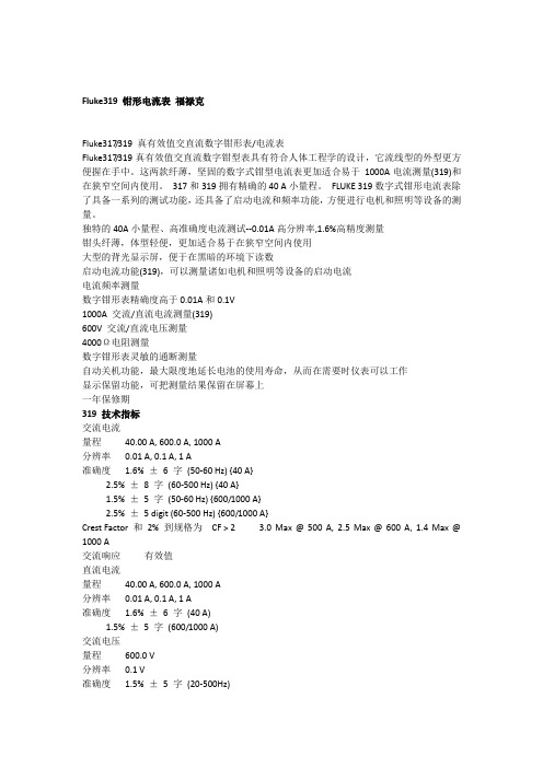

技术资料Fluke 317/319 真有效值交直流数字钳形表/电流表主要特性独特的40A小量程、高准确度电流测试--0.01A高分辨率,1.6%高精度测量钳头纤薄,体型轻便,更加适合易于在狭窄空间内使用大型的背光显示屏,便于在黑暗的环境下读数启动电流功能(319),可以测量诸如电机和照明等设备的启动电流电流频率测量数字钳形表准确度高于0.01A和0.1V1000A 交流/直流电流测量(319)600V 交流/直流电压测量4000Ω电阻测量数字钳形表灵敏的通断测量自动关机功能,更大限度地延长电池的使用寿命,从而在需要时仪表可以工作显示保留功能,可把测量结果保留在屏幕上一年保修期产品概述: Fluke 317/319 真有效值交直流数字钳形表/电流表319数字式钳形电流表除了具备一系列的测试功能,还具备了启动电流和频率功能,方便进行电机和照明等设备的测量。
产品规格: Fluke 317/319 真有效值交直流数字钳形表/电流表所有准确度指标均指 73 °F ± 41 °F (23 °C ± 5 °C)低于 64 °F 和 高于 82 °F (18 °C 和 高于 28 °C)型号Fluke 317/319Fluke 317/319 真有效值交直流数字钳形表/电流表Fluke 319HS1型号:Fluke 319HS1 钳形表包括:Fluke 319 钳形表一台TL75表笔3节 AAA电池IPHS1十字头绝缘螺丝刀Fluke. 让您的工作畅通无阻。
福禄克测试仪器(上海)有限公司 电话:400-810-3435北京福禄克世禄仪器维修和服务有限公司 电话:400-615-1563福禄克测试仪器(上海)有限公司上海维修中心 电福禄克测试仪器(上海)有限公司深圳第一特约维修点©2024 福禄克公司12/2024未经许可,本文档禁止修改。
FLUKE 317数字钳表操作规程GDY/QW-JG-JL-XXXX1 前言本标准起草单位:广州市地下铁道总公司运营事业总部XX中心。
本标准主要起草人:本标准版本号为第X版、第X次修订。
本标准XXXX年XX月XX日发布。
本标准从XXXX年XX月XX日起实施。
本标准由广州市地下铁道总公司运营事业总部XX中心负责解释。
本标准由广州市地下铁道总公司运营事业总部标准化委员会提出。
本标准由广州市地下铁道总公司运营事业总部标准化工作组归口。
2 范围本标准规定适用于FLUKE 317/319数字钳表测量。
3 引用文件无规范引用文件,保留本条款的目的地是为了保持标准的一致性,便于今后的修改。
4 术语和定义无术语和定义,保留本条款的目的地是为了保持标准的一致性,便于今后的修改。
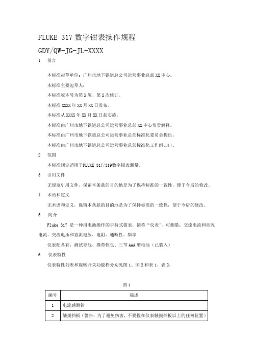
5简介Fluke 317是一种用电池操作的手持式钳表,简称“仪表”,可测量:交流电流和直流电流、交流电压和直流电压、电阻、通断性、频率仪表配备有:测试导线、携带软包、三节AAA型电池(已装入)6仪表特性仪表特性列表和旋转开关功能档分别见图1、图2和表1、表2。
图1表1 仪表特性图2表2 旋转开关7操作规范1.测量交流或直流电流(1)将旋转功能开关转至合适的电流量程。
(2)如果需要,可按“AC/DC”按钮选择直流电流。
默认是交流电流。
(3)如果进行直流测量,先等待显示屏稳定,然后按“ZERO”按钮将仪表归零。
(注意:在归零仪表之前,请确保钳口已闭合并且钳口之间没有导线)(4)按住钳口开关张开夹钳并将待测导线插入夹钳中。
(5)闭合夹钳并用钳口上的对准标记将导线居中。
(6)查看液晶显示屏上的读数。
图3 正确测量电流警告:为了避免触电或人身伤害,流向相反的电流会相互抵消。
一次只能在夹钳中放入一根导线。
图4 错误测量电流2.测量交流和直流电压(1)将旋转功能开关转至“直流/交流电压”。
(2)如果测量直流电压,可按“AC/DC”按钮变换为直流电压。
默认是交流电压。

2021年5期科技创新与应用Technology Innovation and Application方法创新钳形电流表示值误差测量结果不确定度评定张振国(河北前进机械厂,河北石家庄050035)钳形电流表是一种将开合的磁路套在载流导体上测量其电流值的仪表。
它的特点是无需断开回路,即可测量被测电路的电流,操作简单,大量应用于科研生产和检修测试当中。
按照测量原理钳形电流表又可分为互感器式、霍尔效应式以及磁平衡式等。
互感器原理的钳形电流表仅能测量交流电流,霍尔效应原理和磁平衡原理的钳形电流表可测量交直流电流。
钳形电流表的校准方法一般采用单匝法或等效安匝法。
单匝法能对测量数据进行有效溯源,适用于高、低准确度钳形电流表的校准;等效安匝法难以进行测量数据的直接溯源,仅适用于低准确度钳形电流表的校准。
可根据被校钳形表的电流测量范围及准确度等选择合适的测量方法。
本文以常用的FLUKE 319钳形电流表为例,采用等效安匝法,对校准过程中的主要不确定度因素进行分析、评价,希望对相关工作者能起到帮助作用。
1概述1.1校准依据JJF 1075-2015《钳形电流表校准规范》。
1.2环境条件环境温度:(20±5)℃;相对湿度:(55±20)%。
1.3测量标准(1)多功能校准器,型号:5500A ,量程:DCI (0~10)A 。
(2)100匝钳形电流表校准线圈,型号:HG1000A ,量程:DCI (0~1000)A 。
1.4被校对象数字式钳形电流表,型号:FLUKE 319,量程:DCI(0~600)A ,准确度:±(1.5%+5)。
1.5校准方法采用等效安匝法,100匝钳形电流表校准线圈在结构上把多功能校准器输出的电流以100匝形式沿同一方向多次穿过铁芯,因此在100匝线圈导线汇聚的一侧中产生的等效安匝电流是多功能校准器输出电流的100倍。
将多功能校准器5500A 预热30min 后,输出直流电流(0~10)A 给100匝钳形电流表校准线圈,将该线圈放置于钳形电流表钳口几何中心位置,在钳形电流表上读取相应的电流示值,并将此示值与实际值相减,其差值即摘要:文章依据JJF 1075-2015《钳形电流表校准规范》采用等效安匝法测量数字式钳形电流表,在建立测量模型的基础上,以直流100A 为例,分析了不确定度产生的来源、影响因素、对各不确定度分量进行了分析,最终给出测量结果的不确定度报告。
a283 FCWireless AC/DC Current ClampCalibration Information IntroductionXW WarningTo prevent possible electrical shock, fire, or personal injury, read all safetyinformation before you use the Product.The a283 FC Wireless AC/DC Current Clamp (the Product or Clamp) is a wireless True-rms current clamp with a thin jaw to fit into tight spaces.This document has the verification and calibration adjustment procedures for the Product. For complete operating instructions, and routine maintenance procedures, see the a283 FC Instructions at .Contact FlukeFluke Corporation operates worldwide. For local contact information, go to our website:.To register your product, or to view, print, or download the latest manual or manual supplement, go to our website: /productinfo.Safety InformationGeneral Safety Information is in the printed Instructions that ship with the Product and at . More specific safety information is listed in this document where applicable.A Warning identifies hazardous conditions and procedures that are dangerous to the user. A Caution identifies conditions and procedures that can cause damage to the Product or the equipment under test.November 2024©2024 Fluke Corporation. All rights reserved.Specifications are subject to change without notice.All product names are trademarks of their respective companies.a283 FCCalibration InformationXW WarningTo prevent possible electrical shock, fire, or personal injury, keep fingers behind thetactile barrier when you take measurements. See Figure1.Figure 1. Tactile Barrier ArraySpecificationsFor complete specifications, refer to the Users Manual at . Performance TestsXW WarningTo prevent possible electrical shock, fire, or personal injury, do not do theperformance test procedures unless the Product is fully assembled.The performance tests verify the full operation of the Product and measure the accuracy of each function against Product specifications. If the Product fails a part of the test and/or calibrationadjustment, repair is necessary. See Calibration Adjustment.Wireless AC/DC Current ClampPerformance TestsThe performance tests and calibration adjustment require the equipment in Table 1.XW WarningTo prevent possible electrical shock, fire, or personal injury, see the Safety Information document for the 5560A Calibrator available at .Wireless Connection with Fluke 283 FCUse the 283 FC to pair and connect to the Device Under Test (DUT). Check the current output value with the 283 FC. See the 283 FC Users Manual for more detailed information.AC/DC Current TestBefore this test:1.Make sure that you have the necessary equipment. See Table 1.2.Make sure the Product battery is good and replace if necessary.3.Warm up the Calibrator as necessary. Refer to its specifications.4.Let the temperature of the DUT become stable to room temperature.To do the ac/dc current test:1.Place the Product on the 10-turn Coil. See Figure2.2.Connect the Calibrator amp output HI and LO to the 10-Turn Coil. See Figure 2.3.Apply the input current for each step shown in Table 2.pare the indication on the 283 FC with the DUT reading limits in Table 2.5.If the display indication falls outside of the range shown, adjustment or repair of the Productis necessary. See Calibration Adjustment .Table 1. Required EquipmentEquipment Required CharacteristicsRecommended Model Calibrator 4.5-digit resolution AC Current Accuracy:600μA to 30A ±0.25%Fluke 5560A Calibrator (or equivalent)Wired coil 10 turns55XXA/COIL 10Wireless DMM Display current valueFluke 283 FCTTBLE dongleWrite Serial Number for Device Under Test(DUT) and adjust-a283 FCCalibration InformationTable 2. Performance TestsWireless AC/DC Current ClampPerformance Tests Before Calibration AdjustmentBefore you adjust Product calibration, you must turn on the DUT and use the TTBLE dongle to pair and connect to the DUT with the command below.Use the serial communication tool or METCAL to send the command to TTBLE dongle with the serial port set: 115200,8,1,N:AT...AT+BLEMODE=1AT+RESETAT...AT+CLRCONADDAT+SA VEAT+RESETAT...AT+SCAN=ON // wait for the scanned MACAT+CONADD=scanned MACAT+SA VEAT+RESETWhen the PC gets the current value from the DUT, this designates a successful connection.a283 FCCalibration InformationCalibration AdjustmentThe Product features closed-case calibration adjustment and uses known reference sources. The Product measures the applied reference source, calculates correction factors, and stores the correction factors in nonvolatile memory. If the Product fails any of the performance tests, do the calibration adjustment procedure.Connect the Calibrator to the10-turn coil. Clamp the DUT to the coil and then turn on the DUT. See Figure2.Send the command below to check, adjust and change MAC according to serial number of DUT.CAL START // enter calibration mode.LED GREEN // check LEDs colorLED NULL // turn off LEDLED ORANGELED NULLLED REDLED NULLLED BLUELED NULLBALANCE WRITE 124 // step1 Balance, default: 124GET V ALUE//Write and find the value between 32~223 to make the reading difference to be //within ±0.03A at top and bottom of clamp, use GET V ALUE to get reading and //compare.RAW ADCL DATA //step2, ADC zeroRAW ADCH DATA //step3, ADC gainRAW AAC0 DATA//step4, AAC zeroRAW AACL DATA//step5, AAC gainRAW AACM DATA//step6, AAC gainRAW AACH DATA//step7, AAC gainRAW AACMAX DATA//step8, AAC gainIDN WRITE 123456789WS//write in the serial number, example: 123456789WS or 123456789NU// WS: shifu, NU: FPM in NorwichTEMP CALDATE WRITE 20250131// temperature calibration// calibration date, year/month/ dayCAL EXIT // exit the calibration mode.Wireless AC/DC Current ClampMaintenanceRestart the DUT and check the new MAC (serial number) and performance with Fluke 283 FC.For each step in Table 3, output the listed current, and then send the command.MaintenanceClean the ProductW CautionTo prevent possible damage to the Product or to equipment under test, do not useabrasive cleaners. They will damage the case.To clean the Product, use a cloth with a mild cleaning solution.Table 3. Calibration AdjustmentAdjustment PointsSteps Function PointsUnit 5522 Output 1BalanceBalance up:10 turns down:10 turns 60A,60H z6 A, 60 Hz2ADCzeroMiddle:10 turns 0A,0 Hz 0 A3GainMiddle:10 turns 30A,0 Hz 3 A 4AAC zeroMiddle:10 turns 0A,60 Hz 0 A5GainMiddle:10 turns 0.6A,60 Hz 0.06 A,60 Hz 6GainMiddle:10 turns 2A,60 Hz 0.2 A,60 Hz 7GainMiddle:10 turns 30A,60 Hz 3 A,60 Hz 8GainMiddle:10 turns60A,60 Hz6 A,60 Hza283 FCCalibration InformationBattery ReplacementXW WarningTo prevent possible explosion, fire, or personal injury, replace the batteries whenthe low battery indicator (red LED under the power button) shows to preventincorrect measurements.W CautionTo prevent possible damage to the Product or to equipment under test:●Remove batteries to prevent battery leakage and damage to the Product if it is notused for an extended period.●Make sure that the battery polarity is correct to prevent battery leakage.To change the batteries, see Figure3.1.Make sure the Product is OFF.2.Turn the Product over to access the battery compartment door screw.e a flat-head screwdriver to loosen the battery compartment door screw and lift off thebattery compartment door.4.Replace the two AAA batteries. Make sure to observe the correct polarity before you put thebatteries into the battery compartment door.5.Reattach the battery compartment door.6.Tighten the battery compartment door screw.Figure 3. Replace the BatteriesWireless AC/DC Current ClampUser-Replaceable PartsUser-Replaceable PartsUser-replaceable parts are shown in Table4.Table 4. User-Replaceable PartsFluke Part Number Description Qty2687457BATTERY PAD,URETHANE,ADHESIVE-BACK,20.0MM L,20.0MMW,5.0MM THK1 2838018Battery, AAA, IEC LR032 5591547a283 FC CLAMP-2023,RUBBER,SEAL,BATTERY DOOR1 5009651SCREW,CAPTIVE,M3-0.5X8MM,PAN,PHILLIPS,#2,STEEL,BLACK1 4941124SPRING WASHER,M2.5,CARBON STEEL,NICKEL PL16007834 6007847a283 FCCLAMP-8002 STICKER,TTBLE,CLAMP,APAC,-01a283 FC CLAMP-8003STICKER,TTBLE,CLAMP,EMEA&AME&S.AFRICA,-021a283 FC Calibration Information。
用钳形电流表、秒表检查计量综合误差方法
1、电流法公式:P=√3UIcosφ
P实际功率、√3=1.732、U线电压通取0.4kv,cosφ功率因数,动力取0.8,纯照明取0.9,I为三相四线Ia、Ib、Ic实测三相平均电流,即(Ia+Ib+Ic)/3。
三相三线I为实测Ia、Ic的平均电流:(Ia+Ic)/2.
2、秒表法公式:P计=3600×k×n/A×T
P计电表计量功率,3600一小时的秒数,K倍率=CT变比×PT 变比,n电表实测转数,A电表常数(转/KVA),T实测n转的时间。
3、误差率δ=(P-P计)/P,正值综合误差慢,负值综合误差快,0
无综合误差。
4、通常综合正误差较普遍,如出现综合负误差,应检查所取电压、
功率因数是否过高,倍率是否正确。
5、出现综合正负误差,确定是电流、互感器误差的方法。
①首先检查接线是否接错,有无断线;
②电表是否烧坏、或超周期、大盖封签是否齐全,有无伪造现象;
③一次电流经互感器是否成正比下降;
④CT变比(倍率)是否搞错;
⑤电表常数是否看错。
6、检查高供,高计计量时、电压取PT二次电压、100V、电流取
A、C相平均电流、倍率取CT变比乘以PT变比。
Fluke 317 319数字钳形电流表的校准方法
一、进入校准模式
1.按住HOLD键的同时将功能拨盘旋转到V电压档,这时屏幕会显示CAL
2.松开HOLD键,屏幕会显示????
3.输入密码,默认密码是2412
注:各个按键对应的数字如下
仪表按键对应数字
Blacklight 1
AC/DC 2
Hold 3
Zero 4
Inrush (319) 5
Min Max (319) 6
Min Max(317) 5
4.如果没有成功进入校准模式,可以重置密码,方法如下:
将电池后盖打开,按一下隐藏的reset按钮,密码会重置为1234
仪器按键对应功能
HOLD选择校准的参数
Minmax查看需要输入的标准信号
Blacklight 执行校准和保存校准参数注意:当每校完一个点按下Blacklight按键后,如果校准通过,会听到一声长的滴声,如果没通过,会听到3声短的滴声。
三、参数校准方法
关机,可以退出校准模式。