IBM FI模块2
- 格式:ppt
- 大小:428.50 KB
- 文档页数:18

一、设置高级系统管理信息(ASM Information):完成下列步骤来设置Remote Supervisor Adapter II的系统信息:1、登陆到需要设置系统信息的Remote Supervisor Adapter II上;2、在左边的导航栏中,点击System Settings,一个如下图的页面将会显示出来:注意:图中System Settings中的空白的区域内容是由所进入的远程服务器决定的。
3、在ASM Information部分的Name区域,输入Remote Supervisor Adapter II的名称。
使用这个名称可以指定一台服务器中的Remote Supervisor Adapter II,这个名称在e-mail、简单网络管理协议(SNMP)和数字传呼机的报警通知中用于识别来源时都会被用到。
注意:a、如果用户计划建立起一个SMTP简单邮件传输服务器来做邮件方式的报警通知,必须确认在Name区域的名称是可用的邮件地址的一部分。
b、Remote Supervisor Adapter II的名称(在Name区域)和IP主机名称(在Network Interfa ces页面的Host Name区域)不能使用自动共用的同一个名称,因为名称在ASM的Name 区域中被限制在15个字符之内,而在Host Name区域中可以包含63个字符。
为了减少混淆,将Name区域的名称设置为IP Host Name主机名称的一部分。
这个部分的IP Host N ame由完整的IP Host Name的第一段组成。
例如,完整的IP Host Name主机名称是asm ,那么部分的IP Host Name就是asmcard1。
4、在ID number区域,可以为Remote Supervisor Adapter II分配一个唯一的辨认数字。
5、在Contact区域,可以输入联系信息。
例如,用户可以指定一个如果这台服务器发生故障时需要联系的人的名字和电话号码。

NC Cloud1909产品安装指南2019年9月版权所有(c)2019用友网络科技股份有限公司概述本安装指南主要包含以下几部分内容:●注意事项●NC Cloud安装盘介绍●NC Cloud软硬件配置●应用服务器系统配置●数据库系统配置●NC Cloud安装部署●NC Cloud附属工具配置●NC Cloud云融合配置●NC Cloud产品卸载注意事项环境预置配置●Linux应用服务器操作系统需按照应用服务器系统配置要求预先配置。
●文件服务器、应用服务器和数据库服务器部署在同一个网段,通过千兆交换机互联。
避免因为与应用服务器频繁的数据上传下载造成网络问题。
●NC Cloud中任何配置及使用过程中,IP地址禁止使用127.0.0.1和localhost等本地回环地址,否则会出现不可预知的异常错误。
●应用服务器安装操作系统后,请修改服务器的名称,确保在创建WAS概要文件前服务器名称已经修改且不能重复。
部署、安装配置●JDK:NC Cloud默认自带JDK为NCC_HOME/ufjdk,只适用于Widows平台,版本为SUN64位JDK1.8.0_202;安装盘目录下Tools下提供三个jdk,分别为:Linux下SUN64位JDK、Widows下IBM64位JDK、Linux下IBM 64位JDK。
●安装:NC Cloud代码解压路径不要有空格,汉字,非法字符;安装代码时,弹出界面点击下一步没反应时,请将.nchome文件内容置空(window路径C:\Users\Administrator linux路径:/root)。
账套编码不允许使用中文及特殊字符,否则轻量端加载登录页时报500。
●部署本版集群环境支持master与redis两种部署模式,推荐采用master模式部署,NC Cloud适配Reids部署请参照文档《NC Cloud1909集群适配Redis部署》;集群要求配置专属的搜索服务器,系统中人员,客户,供应商和物料会使用专属搜索服务器的全文检索功能。
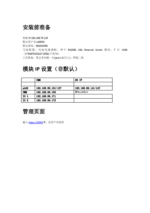
安装前准备初始IP:192.168.70.125默认用户名:USERID默认密码:PASSW0RD当前配置:风扇电源满配、两个EN2092 1Gb Ethernet Switch 模块、7台 X440(2*E4670/32G/2*250G/千兆*4)工具准备:笔记本电脑一台(jave 1.6以上)、网线二条模块IP设置(非默认)IMM OS IPx440 192.168.86.131-137 192.168.86.141-147CMM 192.168.86.100 @Passw0rdIO 1 192.168.86.171IO 2 192.168.86.172管理页面输入https://CMM IP、及用户名密码初始页面(可以看到前后视图及部件状态)系统组件任意选取一台服务器或者部件查看详细信息(日志、详细配置、微码),先看下CPU内存信息(可以显示哪些槽位有内存、每条内存的大小)系统信息Multi‐Chassis Monitor事件导出日志保存日志Services and support问题反馈Setting激活IBM远程支持(需要购买授权、方便没有管理员的企业使用)机箱管理chassisAir flowIdentification 下可以设置计算机的名称之类、不太常用。
Handware activity 下可以查看当前所有激活的服务器及模块。
Temperture可以查看当前的温度(满配20.50 度)还可以选择某一时间段温度的变化情况。
AIR FLOW节点控制当前服务器列表及状态如图所示:开始远程控制选择控制类型弹出如下JAVA 提示框,问啥都要继续了提供两种远程模式、Use the ActiveX Client /Use the Java Client 任选其一、单用户及多用户模式根据实际情况选其一。
又要提示、照例继续。
在上图点击RUN 后终于弹出服务器控制窗了我们来看看菜单有啥、第一项FILE 只有一个capture file 帮助大家来抓图第二项 view主要是帮大家设置显示效果、色彩、全屏之类第三项macros 主要是各种组合键、相当齐全、还嫌不够的话就自己选择soft key 去ADD 吧。

—DATA SHEETRLM02Redundancy Link Module for PROFIBUS DP/FMSThe RLM02 converts a non-redundant PROFIBUS line totwo redundant RS485 linesor vice versa.Benefits• Conversion of one simple, non- redundant PROFI-BUS line into two reciprocally redundant lines A/B • Use on PROFIBUS DP/FMS lines• Automatic line selection• Transmission rate 9.6 kbit/s... 12 Mbit/s• Monitoring of communication• Repeater functionality• Redundant power supply• Status and error display• Monitoring of the power supply• Potential-free alarm contact• Simple assembly on DIN mounting rail FeaturesYou can position the module directly after a master, before a bus segment with several slaves or before an individual slave. PROFIBUS stations with redun-dant couplers [K] can be directly connected to the PROFIBUS set redundant by RLM02.Stations with only one interface can be optionally assigned to the A or B line. Each RLM02 PROFIBUS interface can serve up to 31 PROFIBUS stations. Us-ing repeaters [R] and media converters [O/E] makes it possible to increase the length of the PROFIBUS lines and the number of stations.FunctionThe three RS 485 interfaces of the module support all transmission rates specified in IE C 61158-2 for the PROFIBUS from 9.6 kbit/s to 12 Mbit/s. The module has repeater functionality, i.e., it regener-ates the signal shape and the amplitude of received data. RLM02 monitors all three lines A, B and M for activity and error states.Detected errors are signalled by LEDs (light emitting diodes) on the front panel. The potential-free alarm contact activated in parallel to this can be polled for diagnostic purposes by the process control system PCS or by a programmable logic control PLC. The three serial RS 485 interfaces are potential-free rela-tive to each other and to the power supply. This is a functional electrical isolation.The first data coming in over line A or line B with a correct telegram start are routed to terminal M.With simultaneity, either line A or line B is selected at random. Testing and selection is always based on the first character. In the case of a telegram start with error on A, the control logic switches to the re-dundant line B. The same procedure applies vice-versa for line B.Data coming in over line M with a correct telegram start are routed in parallel to the two terminals A and B. The test for data is always based on the first char-acter. In the case of a telegram start with error, the control logic does not output any data to A and B.Either a single or a redundant power supply with 24VDC is possible. The distribution of load across L1+and L2+ is based on the level of the voltages applied.If a voltage source fails, the switch to the redundant supply source is made without interruption. A moni-toring logic circuit tests whether both voltages are present.Note: Further information see the user manual3BSE092754 Device Management PROFIBUS DP FMS Redundancy Link Module RLM02.ConstructionThree Sub-D connectors A, B and M are located on the front panel of the RLM02 for connection of the PROFIBUS cable. The 8-pin male multi-pin connector with the associated terminal strip is used to connect the alarm and power supply wires. There are also LEDs for activity/error display, a rotary switch for setting the transmission rate and a reset button (ac-tivate transmission rate).Connectors/ TerminalsAdjustment andindicationTechnical data2Ordering InformationPricebook: Freelance, 2PAA118841 / Price list: Freelance, 2PAA10897733B D D 011641 e n A— solutions.abb /800xA solutions.abb /controlsystems —800xA is a registered or pending trademarkof ABB. All rights to other trademarks reside with their respective owners.We reserve the right to mak e technical changes to the products or modify the contents of this document without prior notice. With regard to purchase orders,the agreed particulars shall prevail.ABB does not assume any responsibility for any errors or incomplete information in this document.We reserve all rights to this document and the items and images it contains. The reproduction, disclosure to third parties or the use of the content of this document –including parts thereof – are prohibited without ABB’s prior written permission.Copyright© 2020 ABB All rights reserved。


Steps to configure IBM DS Series Storage for connectivity to MAC clients using the ATTO Celerity Fibre Channel host adapter.Note: Refer to the Digital Media installation guide for detailed installation instructions (found at/solutions/IBM/fibrechannel_ds_storage.html).For Apple Clients1. Set host type LNXCLVMWARE2. Enable TPGS using the script later in this documentFor Linux Clients mixed with Apple ClientsIt is important to use the proper host type definitions if Apple servers or clients are sharing physical connection to a storage system with Linux servers or clients. The MDC’s in the approved solutions will always be Linux (Windows will also be supported in the near future). Clients can be Apple or Linux (and also eventually Windows). To allow disparate O/S host connections:1. Create a Host Group with no Host Type associated2. Create individual Hosts with specific Host Types for each client or server.3. Use the LNXCLVMWARE for Apple, use the LINUX host mode for Linux servers and clients.4. Set AVT Off for all Host Types using the script later in this document5. Enable TPGS for the MAC clients using the script later in this documentRecommended cache settings: Set pre-fetch value to any number other than 0 (zero) to enable automatic prefetch.For clients, limit the number of defined paths to four. This gives you the redundancy you need while minimizing boot time. During boot, StorNext tries EVERY defined path.CONFIGURATION SCRIPTS:Setting TPGS OnThis script turns on TPGS for host type LNXCLVMWARE (which is what we are using for OSX).Set TPGS on by running the script below from the Management GUI:show controller[a] HostNVSRAMbyte[13,0x28];set controller[a] HostNVSRAMbyte[13,0x28]=0x02;show controller[a] HostNVSRAMbyte[13,0x28];show controller[b] HostNVSRAMbyte[13,0x28];set controller[b] HostNVSRAMbyte[13,0x28]=0x02;show controller[b] HostNVSRAMbyte[13,0x28];reset controller[a];reset controller[b];Turning AVT OffThis script turns off AVT for all host types. Set AVT off for all HOST REGIONS by running the scripts below from the Management GUI:/* Disable AVT in all host regions */set controller[a] HostNVSRAMByte[0x00, 0x24]=0x00; /* 0x01 is enable AVT */set controller[a] HostNVSRAMByte[0x01, 0x24]=0x00;set controller[a] HostNVSRAMByte[0x02, 0x24]=0x00;set controller[a] HostNVSRAMByte[0x03, 0x24]=0x00;set controller[a] HostNVSRAMByte[0x04, 0x24]=0x00;set controller[a] HostNVSRAMByte[0x05, 0x24]=0x00;set controller[a] HostNVSRAMByte[0x06, 0x24]=0x00;set controller[a] HostNVSRAMByte[0x07, 0x24]=0x00;set controller[a] HostNVSRAMByte[0x08, 0x24]=0x00;set controller[a] HostNVSRAMByte[0x09, 0x24]=0x00;set controller[a] HostNVSRAMByte[0x0a, 0x24]=0x00;set controller[a] HostNVSRAMByte[0x0b, 0x24]=0x00;set controller[a] HostNVSRAMByte[0x0c, 0x24]=0x00;set controller[a] HostNVSRAMByte[0x0d, 0x24]=0x00;set controller[a] HostNVSRAMByte[0x0e, 0x24]=0x00;set controller[a] HostNVSRAMByte[0x0f, 0x24]=0x00;set controller[b] HostNVSRAMByte[0x00, 0x24]=0x00; /* 0x01 is enable AVT */ set controller[b] HostNVSRAMByte[0x01, 0x24]=0x00;set controller[b] HostNVSRAMByte[0x02, 0x24]=0x00;set controller[b] HostNVSRAMByte[0x03, 0x24]=0x00;set controller[b] HostNVSRAMByte[0x04, 0x24]=0x00;set controller[b] HostNVSRAMByte[0x05, 0x24]=0x00;set controller[b] HostNVSRAMByte[0x06, 0x24]=0x00;set controller[b] HostNVSRAMByte[0x07, 0x24]=0x00;set controller[b] HostNVSRAMByte[0x08, 0x24]=0x00;set controller[b] HostNVSRAMByte[0x09, 0x24]=0x00;set controller[b] HostNVSRAMByte[0x0a, 0x24]=0x00;set controller[b] HostNVSRAMByte[0x0b, 0x24]=0x00;set controller[b] HostNVSRAMByte[0x0c, 0x24]=0x00;set controller[b] HostNVSRAMByte[0x0d, 0x24]=0x00;set controller[b] HostNVSRAMByte[0x0e, 0x24]=0x00;set controller[b] HostNVSRAMByte[0x0f, 0x24]=0x00;show storageArray hostTypeTable;。
X20IF27721 General informationThe interface module can be used to expand the X20 CPU for specific applications. It is equipped with 2 CAN bus interfaces.•Dual CAN bus connection•Integrated terminating resistorsInformation:This module does not support CAN RTR messages with extended CAN identifiers (29-bit) (memory/per-formance bottleneck).2 Order dataTable 1: X20IF2772 - Order data3 Technical dataTable 2: X20IF2772 - Technical data 1)This CAN bus interface can be configured as a CANopen master in Automation Studio 3.0 and higher.4 LED status indicators5 Operating and connection elements6 CAN bus node numberThe node number for the CAN bus interfaces is set with the two hex switches.7 Interfaces CAN bus 1 and CAN bus 2 (IF1 and IF2)Both interfaces feature a 5-pin multipoint plug. The 0TB2105 terminal block must be ordered separately.8 Terminating resistorTwo terminating resistors are integrated in the interface module. The respective resistor can be turned on and off with a switch on the bottom of the housing. An active terminating resistor is indicated by the "TERM CAN 1" or "TERM CAN 2".9 FirmwareThe module comes with preinstalled firmware. The firmware is a component of Automation Studio. The module is updated to this version automatically.To update the firmware contained in Automation Studio, a hardware upgrade must be performed (see "Project management - Workspace - Upgrades" in Automation Help).。
小贴士:什么是SAP中的FICO模块?--- IBM ERP项目小组说到SAP,人们通常首先会提到的就是FICO模块。
因为,一个企业在实施SAP系统时,可以根据企业的性质和需求不上销售模块或者生产模块等,但几乎所有实施SAP的企业都必须上FICO模块,可以说FICO是SAP最核心的组件。
那么,究竟FICO代表着什么,它有哪些功能呢?本文就是来简单介绍SAP的FICO模块。
FI代表英文单词Finance财务会计的缩写CO代表英文单词Controlling管理会计的缩写FI和CO其实是SAP财务会计系统的两大组成部分:⏹FI,重点关注财务会计,即外部会计,关注的是按照一定的会计准则,组织账务,并出具满足财税等外部实体及人员要求的法定财务报表,通常比较标准。
⏹CO,重点关注管理会计,即内部会计,通常比较灵活,出具的报表是为了满足内部管理机构及相关人员的需要。
图1:财务会计和管理会计分别面对的人群首先,我们来看FI 包括哪些内容:应付帐款应收帐款固定资产总帐SAP FI图2:SAP FI 的组成总账:– 会计科目表维护 – 科目余额 – 周期处理 – 过账 – 结账资产会计:– 资产主记录– 采购、转移、清理、报废 – 折旧财务分析保险公司审计师税务当局股东政府部门银行媒体行政人员中层经理各部门、员工内审官员 高层管理人员应付账款:–供应商主记录维护–发票管理–科目余额–支出/预付–汇票–自动付款应收账款:–客户主记录维护–发票管理–科目余额–收入/预收–汇票–借贷管理其次,在SAP的CO中,包括以下内容:获利性分析利润中心会计基于活动成本法经营费用SAP CO生产成本图3:SAP CO的组成成本中心和内部订单会计:–预算/计划–费用分配–下拉报表基于活动成本法:–业务流程–作业分配生产成本:–产品成本计划–成本对象控制获利性分析:–获利段分析–收入/成本收集– 标准成本与移动平均价利润中心会计:– 利润中心分析 – 收入/成本收集SAP 是个高度集成的系统,那么它的FICO 财务模块是如何与其他系统集成的呢? 1)FI 模块的集成性图4: FI 与其他模块的集成图4是SAP FI (财务会计)模块与其他模块之间的集成图。
实用标准文档第一步,要按照如下方法把IMM2的IP 改成下图中的规格。
启动服务器后,可以使用BIOS 设置工具管理IMM 网络连接.开启服务器,通电大约两 分钟后,电源控制按钮将会激活,按下开机按钮,就会显示IBM System x Server Firmware 欢迎界面.按下F1 键.在 Setup utility 主窗口中,选择 System Settings - Integrated Management Module - Network Configuration.在 DHCP Control中有三个 IMM 网络连接选项(Static IP,DHCP Enabled,DHCPwith Failover(default). 选择其中一种网络连接方式.如果选择static IP ,须指定IP 地址,子网掩码,网关.(IP address,subnet mask and default gateway).设置完后选择 Save NetworkSett in gs 保存,退出 Setup utility.第二步,要在IBM 官网上下载以下两个文件(分别是 UEFI 和IMM2的升级文件)----------------------- 1Mtnrk CowfifuratliHi6Netuork Interface PortFaiPDver hile EuiiHfd In fkldrcssH DS I IUK<Ded kdted> <Mone> 40-r2-E9-?4^D-&E---This option wl)I illou youto select ijour Systen 能畑胆帕就 Network Inter 巾u Pn 「t ・DHCP CcHitrol IP Address Subtil Hdsk Derault Gdietuy (Static IP> 1324G6.70.125 25S.JS5,255.e 9.6.0.0inLomE Link Address<Endbled> FE8O ::42F2:E1FF :也4:9D 6E/S4114-floue Highlight <Enter>=Select E^itry Eac-Exlt(1.506M] DIMH Pbpu lat Inn Change Detected实用标准文档IEiM D EF-I l-las^i Update以下文件将彌该补「dn I bmjw_uefi_vv&15Qc-Z22_anyos_32-64,Ghg (13.2 KB) i d i ibir fv/ uc J i /7^153c-2.22 j" /U5 32-0-. 'Eitli 197 &j ibnn uefi we150c-Z22_anyos_32-64<txt (16-02 KB)以下■文件将丈為该补丁。