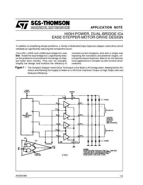
APPLICATION NOTEAN238/0488EASE STEPPER-MOTOR-DRIVE DESIGNHIGH-POWER,DUAL-BRIDGE ICsIn addition to simplifying design problems,a family of dedicated chips improves stepper-motor drive-circuit reliability by significantly reducing the component count.Figure 1:The Simplest Stepper-motor Drive Technique is the Basic L/R Configuration.Adding Series Re-sistors and Raising the Supply to Make an L/4R Drive Improves Torque at High Steps rates but Reduces Efficiency.The L293,L293E and L298N dual-bridge ICs (see box ,”inside the dual-bridge ICs”)significantly redu-ce the problems encountered in the design of step-per-motor drive circuitry.They can,for example,simplify the design and increase the efficiency ofconstant-current choppers.And with a single chip replacing the transistors and predriver stages,cir-cuit performance improves.Best of all,the devices have applications in complex as well as basic driver networks.1/8SIMPLEST DESIGN IS AN L/R DRIVE The simplest motor-drive configuration (fig.1)con-sists of a µC that performs the translator function in software (see box ,”Generating switching sequen-ces”)and drives the motor through a L293dual brid-ge.Only eight external components are required ;these are diodes that protect the device’s output transistors againstinductive spikes generatedwhen a winding de-energizes.The L293handles 1A continuous(for higher currentuse and L298N).However,if you plan to run the mo-tor continuously with two phases on,dissipation will be the limiting factor.You can improve the performance of this basic L/R drive by increasing the series resistanceand raising the supply voltage to restore the original phase cur-rent.At high speeds,torque improves,but efficiency decreases.Normally,you increase each winding’s resistance by a factor of four through the addition of a 3R series resistance,resulting in the L/4R drive.Dual-bridge driver ICs reducethe partscount ofbipolar steppermotors andsimplify design.The sche-matic of the L298N is functionally similar to those of the L293and L293E.INSIDE THE DUAL-BRIDGE ICsThe L293,L293E and L298N (figure)contain two po-wer-transistor bridges,predriver stages,control logic and protection circuitry.There’s a control input for each bridge and an enable input for each half bridge ;inputs connect directly to µCs,CMOS or TTL.The ICs inte-grate level shifters with a separate logic-supply pin.For current sensing,the L293E and L298N have external emitter connections.A single package drives a 2-phase bipolar stepper mo-tor,challenging the assumption held by many that uni-polar motors are easier to drive.You can use a bipolar motor -simpler and less expen-sive than a unipolar motor -without building complex power stages.Furthermore,you don’t have to worry about simultaneous conduction of a half bridge’s sour-ce and sink transistors -a basic problem with discrete-component bridge circuits.Chip design makes it impossible for both transistors to be on at the same time.Designers should also discard the mistaken idea that constant-current chopper drivers are complicated and expensive.You can build one with two bridge ICs and a few passive components.Type I O I O(PEA K)V S Package Sensing Connections L2931A 1.5A 36V DIP16L293E 1A 1.5A 36V DIP20One per Half Bridge L298N2A2.5A46VMultiwatt15One per BridgeAPPLICATION NOTE2/8MULTIPLE SUPPLIES BOOST PERFOR-MANCEA dual-level supply also improves the performance of a basic L/R circuit.A high supply voltage yields good torque characteristics when the motor is run-ning.A lower-than-rated voltage provides some hol-ding torque when the motor is at rest,therebysaving power when the motor is idle.Fig.2shows a suitable voltage-switch circuit.R x sets the holding current,which can be low because a permanent magnet or hybrid stepper motor provi-des some holding torque at zero current.However, make certain the L293’s motor-supply input never goes below the logic-supply voltage.While there’s no danger of damaging the device,it’s imposssible to drive the output transistors correctly under such conditions.The dual bridge’s enable inputs offera meansof ex-tending the chip’s flexibility.For example,you can connect them directly to the logic supply-no resi-stors are needed-to enable the chip permanently. As an alternative,use the enable inputs to disable the motor during the power-on reset sequence.In wave-drive and half-step modes,use the enable inputs to increase torque at high speeds.When a winding de-energizes,flux collapse is a function of the current-decay rate.During this decay,the de-energized winding opposes the efforts of the next winding in sequence,partially cancelling the torque.You can minimize this effect by disabling a bridge only when the winding it drives is turned off;becau-se the∆i/∆t of an inductor equals E/L,disabling the bridge acceleratesthe current decay.This action di-scharges the winding’s stored energy through its supply and maintains the terminal voltage E at V s plus two diode drops.If you were to leave the bridge enabled,the current would flow to ground through one diode and one transistor,and it would lower the terminalvoltage.This scheme doesn’t applywith dri-veswithtwophaseson becauseno winding ever de-energizes.Figure2:Switching the Supply to a Lower Volt-age when the Motor is Idle Saves Cur-rent without Compromising DrivingPower.Figure3:Maintaining a Constant-average Phase Current this Fixed-ripple Chopper Provides Improved Performance and Efficiency V REF Controls the Phase Current.APPLICATION NOTE3/8GENERATING SWITCHING SEQUENCESIn addition to selecting a motor and determining power-stage design,you must also decide how to generate the switchingsequences thatstepthe motor.Programming a µC or using a special piece of hardware called a tran-sistor accomplishes this task.Software translation is more economical,and it is the first choice for large-volume products.Fig.A shows a basic step procedure (a)that you can integrate into a routine (b);the routine executes a clockwise rotation of N steps at a fixed rate.The step rate is defined by a software loop,but you can also use programmed timer interrupts.Fig.A :A µC can generate the phase sequence (a)for a stepper motor.A routine (b)expands a single-step routine into are that executes a move of N steps.A simpler approach uses the software equivalent of a shift register.For example,you can load a 99(hex)into a register and take the phases from bits 0to 3.A Rotate Left instruction yields a clockwise step ;a Rotate Right instruction causes a counterclockwise move.When software translation ties up your µC,lighten the load by adding a hardware translator.In applications in-volving unidirectional motors,this logic circuit (fig.B)re-quires only one pulse for each step ;you’ll also need a direction signal (b)if your motor rotates in both direc-tions.By adding a 7408to a 2-phase translator,you can satisfy a wave-drive application (c),while the addition of two OR gates provides fast turn-off in wave-drive mode.Fig.B :Built a simple 2-phase hardware translatorusing a dual flip-flop,for single (a)or bidirec-tional (b)rotation.Add some extra ICs for wave-drive signals (c)and to provide fast turn-off (d).a)b)b)c)d)a)APPLICATION NOTE4/8Often aµC controls the translator,setting the direction line and providing a pulse for each step.Software is thus simplified,and if you use a programmed interrupt scheme,theµC is free to handle other tasks.Fig.C de-scribes an absolute-positioning routine for a step with a direction-control translator;Fig.D outlines how pro-grammed timer interrupts are used to relieve the bur-den on the C.Two special cases call for hardware translation.The first is in a system for which you have already designed in control circuitry to provide step and direction signals. The second case involves single-quantity and small-run applications,in which thecost of a fewICs is a small price to pay for simplified software.Figure C:For use with a Hardware Trans-lator this a Absolute-positioningRoutine Sets the Direction Lineand Sends the AppropriateNumber of Step Pulses. Figure D:To Set a motor Step Rate,usedProgrammed Timer Interruptsin Place of Software TimingLoops.Notes:Enter with de-sired position current po-sition in register or mem-APPLICATION NOTE5/8CHOPPER CIRCUIT OFFERS MORE EN-HANCEMENTSAdding a chopper circuit to maintain a constant-ave-rage phase current improves performance and effi-ciency.Fig.3showna simple constant-currentdrive that employs a dual bridge,dual comparator and a few passive components.This circuit requires an L293E,because this dual-bridge IC offers access to the lower emitter connections,thus letting you insert current-sensing resistors.Operation of this fixed-ripple chopper drive is strai-ghtforward.When theµC or translator activates a bridge,theincreasing load current raises thevoltage across the sensing resistor until it equals the com-parator’s reference voltage.The comparator then switches,clamping the translator signals through the diodes to deactivate the bridge.As the current decays,the voltage across the sensing resistor de-creases until it equals the comparator’s lower thre-shold.The comparator switches again,allowing the µC or translator to activate a bridge and restart the cycle.Aslong as the translatordrives the bridge,this sequence repeats to provide a constant-average phase current with fixed ripple.V ref adjuststhe lower current limit,while the compa-rator’s hysteresis sets the ripple,and hence the peak current.Although a divider establishes the va-lue of V ref in this case,you can employ the dual-sup-ply design approachand switch V ref toa lower value when the motor is idle.In addition,use of a D/A con-verter establishes V ref for micro-stepping applica-tions.This drive circuit,with its fixed-ripple current characteristics,is well suited for such service. FIXED-FREQUENCY CHOPPER IS MOTOR INDEPENDENTFig.3’s drive has some disadvantages.First,the chopper frequency depends on motor characteris-tics,and these parameters vary from unit to unit.In addition,it’s impossible to synchronize the chop-pers,and this shortcoming can cause trouble on the ground plane.Using a flip flop/comparator arrangement(fig.4)to develop a fixed-frequency chopper overcomes the-se problems.In this circuit,the NE555timer gene-rates negative pulses that reset the flip flops to enable the phase-controlsignalsfrom the translator. If these signals are set to energize a winding,theFigure4:This Fixed-frequency Constant-current Chopper Driver Enables the Synchronization of Several Drives,thus Minimizing Potential Ground-plane Problems.APPLICATION NOTE6/8Figure5:A Special Translator-chopper Control Circuit cuts the Drivers Components Count to the Mini-mum.current in that winding rises until the voltage across the sensing resistor switches the comparator,thus setting the flip flop.This disables the phase signals and deactivates the bridge.Current in the winding falls until the next clock pulseresets the flip flop,and the sequence repeats to maintain a constant cur-rent.CONTROLLER IC REDUCES COMPONENT COUNTIf you’re using a hardware translation and constant-current choppers,you can further reduce the com-ponent count by using a controller chip such as the L297–a20-pin DIP that houses a translator and a dual fixed-frequencychoppercircuit.Under the con-trol of step and direction inputs,the L297generates normal,wave-drive and half-step sequences.As shown in fig.5,the controller connectsdirectly to a dualbridge.Externalcomponentrequirementsare minimal:and RC network to set the chopper fre-quency and a resistive divider to establish the com-parator reference voltage(V ref).To accommodatemotorswith a phase currentasgreat as3.5A,replace the single dual-bridge ICwith two de-vices configured in parallel(input to input,enable to enable,etc)to form a single bridge.It’s extremely im-portant thatyou pair the half bridges–1with4and2 with3–to ensure optimum current sharing.Reprinted from EDN.11/24/83©1986CahnersPublishing Company Division ofReed Publishing USA.APPLICATION NOTE7/8APPLICATION NOTEInformation furnished is believed to be accurate and reliable.However,SGS-THOMSON Microelectronics assumes no responsibility for the consequences of use of such information nor for any infringement of patents or other rights of third parties which may result from its use. No license is granted by implication or otherwise under any patent or patent rights of SGS-THOMSON Microelectronics.Specifications mentioned in this publication are subject to change without notice.This publication supersedes and replaces all information previously supplied.SGS-THOMSON Microelectronics products are not authorized for use as critical components in life support devices or systems without express written approval of SGS-THOMSON Microelectronics.©1995SGS-THOMSON Microelectronics-All Rights ReservedSGS-THOMSON Microelectronics GROUP OF COMPANIESAustralia-Brazil-France-Germany-Hong Kong-Italy-Japan-Korea-Malaysia-Malta-Morocco-The Netherlands-Singapore-Spain-Sweden-Switzerland-Taiwan-Thaliand-United Kingdom-U.S.A.8/8。