autoCut使用说明书
- 格式:doc
- 大小:108.50 KB
- 文档页数:10
![[专题]线切割Autop使用说明书](https://img.taocdn.com/s1/m/122f2a26b80d6c85ec3a87c24028915f804d8407.png)
Autop 的软件界面一、3B 代码格式和Autop 的作图思想Autop 的作图是以模拟手工作图为主的,这是一种不同于经典CAD 的作图思想。
一般来说,经典CAD 的作图思想追求的目标是“科学高效”,Autop 的作图思想仅限于满足“简单朴素”这样的一般目标。
Autop 软件的诞生始于十多年以前,十多年过去以后,Autop 依然受欢迎,这其中除了惯性在起作用外,更多地是由于Autop 采用了一种更适宜于线切割软件编程的作图思想。
线切割编程同经典CAD 编程并不完全相同,线切割编程要简单得多,是CAD 平面作图的一个子集。
另外,同普通CAD 编程强调轮廓的特点不同的是,线切割编程更多地是强调“连接”。
但在我们了解Autop 的作图思想之前,我们需要先来分析一下线切割编程的目标——产生3B/4B 代码,从而帮助我们了解为什么线切割编程需要强调“连接”,并进而理解Autop 的某些作图思想。
如果将线切割机床比作一个人的话,那么这就是一个只会“X 走”或“Y 走”的人。
3B 代码使用了X 位移数据或Y 位移数据其中之一作为加工进度标志,并根据加工进度相应调整X 位移和Y 位移。
由于加工进度标志只使用单一数据,所以需要使用加工方向(加工指令Z )来辅助决定加工状态。
对于直线代码来说,根据直线指向象限存在L1、L2、L3、L4四种情况。
对于圆弧代码来说,根据圆弧出圆弧所在象限和旋转方向存在NR1、NR2、NR3、NR4,SR1、SR2、SR3、SR4八种情况。
决定使用计数方向GX 或GY 的原则是得到更好的加工精度,对于直线代码来说,当终点Y 数值大于X 数值(落在图1阴影区内),采用计数方向GY 显然可以获得更好的加工精度(较大的数值乘以斜率结果也更大,因而数值更精确);对于圆弧代码来说,如果终点在图2阴影区里时在最后这一段X数OXY 按钮,在需要输入原点、X 轴、Y 轴时点击相应按钮可以代替键盘输入。


参数化自动绘制刀模图
(联系方式:蔡汉春手机:137********)
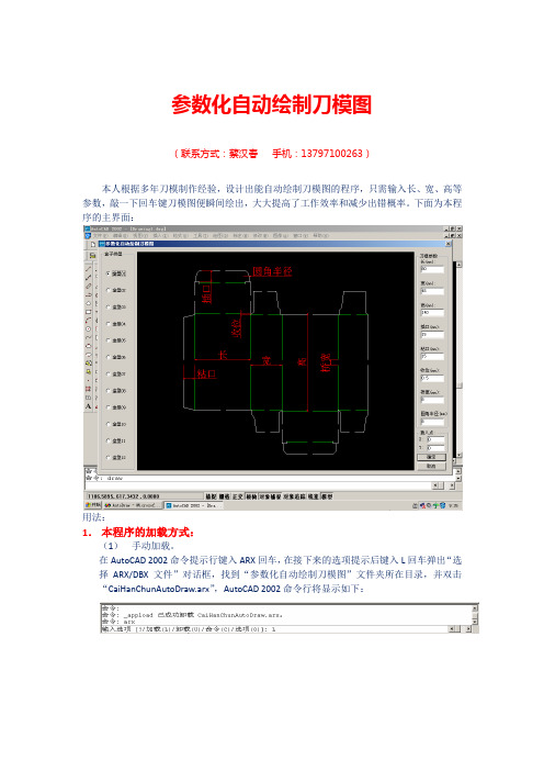
本人根据多年刀模制作经验,设计出能自动绘制刀模图的程序,只需输入长、宽、高等参数,敲一下回车键刀模图便瞬间绘出,大大提高了工作效率和减少出错概率。
下面为本程序的主界面:
用法:
1.本程序的加载方式:
(1)手动加载。
在AutoCAD 2002命令提示行键入ARX回车,在接下来的选项提示后键入L回车弹出“选择ARX/DBX文件”对话框,找到“参数化自动绘制刀模图”文件夹所在目录,并双击“CaiHanChunAutoDraw.arx”,AutoCAD 2002命令行将显示如下:
在“命令:”后键入“draw”回车,便会出现“参数化自动绘制刀模图”对话框。
(2)自动加载
双击“ObjectARX程序的自动加载”文件夹中的“AutoLoadArx.exe”文件,弹出如下对话框:
点击“选择文件:”右边的浏览按钮,会弹出“打开”对话框,找到“X:\刀模图自动绘制\CaiHanChunAutoDraw.arx”(X为本文件所在盘符)文件路径,并双击“CaiHanChunAutoDraw.arx”文件,然后单击“确定”按钮,这样当AutoCAD 2002每次启动时便会自动加载“CaiHanChunAutoDraw.arx”文件,如下所示:
2.程序的运行
在“命令:”中按提示输入“draw”,如下所示:
敲回车后弹出“参数化自动绘制刀模图”主界面,如下所示:
3.根据需要选择盒型,并设置所需参数,点确定,一张刀模图便瞬间绘出。
以下是自动绘制刀模图的截图:。

Autodesk®Factory Design SuiteThe flexibility to innovate,in one cost-effective package.Rendering of factory interiorwith DWG™ underlay. Autodesk®Factory Design Suite andAutodesk® 3ds Max® Designsoftware products were used inthe design process.Extend the Benefits of Digital Prototyping to the Factory FloorAutodesk Factory Design Suite combines the power of AutoCAD with the benefits of Digital Prototyping—so you spend less time drafting, and more time optimizing and visually communicating factory layouts.Autodesk® Factory Design Suite is an integrated2D and 3D factory layout and optimization solution that can help you create more efficient factory layouts by developing a digital model of your factory. The solution complements AutoCAD®and Autodesk® Inventor® software with workflows that enhance accuracy, design efficiency, and communication.Win More BusinessCreate factory layout models that help you quickly evaluate multiple what-if layout scenarios, so you can determine the best solution before any equipment is installed. Use factory-specific visualization tools to impress potential clients with immersive and interactive layout proposals in 3D rather than difficult-to-interpret multilayered 2D drawings.Optimize Your Factory Layout ProcessUse Factory Design Suite to create layout designsmuch faster than you could with traditional factorylayout workflows. Analyze existing 2D layouts formore efficient material flow and transform layoutliabilities into profit-generating assets. IncorporatePoint Cloud scans to capture the as-built stateof your factory, drastically reducing manualmeasurement. Perform engineering reviews andexplore factory layouts with interactive 3D virtualwalk-throughs. And because Factory Design Suitesupports the DWG™ file format, you can continueto use valuable legacy data and improve yourfamiliar AutoCAD workflow without making drasticworkflow changes.Meet Tight Project SchedulesWork faster with automated workflows and afactory-centric work environment in both AutoCADand Autodesk Inventor software. Automaticallyconvert 2D drawings into 3D layout models.Then integrate reusable 3D machine and factorycomponent models to find the most optimal layoutsolution.Collaborate More Effectively with Suppliers andPartnersDevelop immersive, high-quality 3D animations andvisualizations to improve communication. Includemodels from suppliers—regardless of CAD format—in your layout, shrink-wrapping and stripping themof unwanted details. Reduce installation risks byanalyzing the digital factory model for clashesand space constraints before they become on-siteproblems.Autodesk Factory Design Suite Standard • AutoCAD ® Architecture• AutoCAD ® Mechanical• Autodesk ® Vault• Autodesk ® Showcase ®• Autodesk ® Factory Design Suite Utilities Autodesk Factory Design Suite Premium • Autodesk ® Inventor ®• Autodesk ® Navisworks ® Simulate • Autodesk ® 3ds Max ® Design • AutoCAD ® Architecture• AutoCAD ® Mechanical• Autodesk ® Vault• Autodesk ® Showcase ®• Autodesk ® Factory Design Suite Utilities Autodesk Factory Design Suite Ultimate • Autodesk ® Inventor ® Professional • Autodesk ® Navisworks ® Manage • Autodesk ® 3ds Max ® Design • AutoCAD ® Architecture • AutoCAD ® Mechanical • Autodesk ® Vault • Autodesk ® Showcase ®• Autodesk ® Factory Design Suite UtilitiesAutodesk Factory Design Suite offers:• 2D and 3D visual layout environment . Test what-if scenarios by dragging anddropping 3D models of machine andfacilities content onto your 2D floor plan.• Large library of factory assets .Access, resize, and reuse out-of-the-box 2D and 3D parametric factory content such as conveyors, material handling equipment, and facility equipment.• Factory asset builder .Use Autodesk Inventor software to create 3D models of factory equipment, or tomore easily import suppliers’ factory assets into your layout.• Factory design efficiency .Automate repetitive manual tasks,automatically convert 2D drawings into 3D layouts, and save time on measurements by using laser scanning.• 3D factory visualization and analysis . Collaborate better with immersive high-quality renderings and visualizations.Reduce installation risks by exploring digital factory models with interactive 3D virtual walk-throughs and fly-throughs.Learn how Autodesk Factory Design Suite can accelerate your factory layout process at /factorydesignsuite .Build Your Digital Factory Autodesk Factory Design Suite adds factory-specific functionality to AutoCAD, Autodesk Inventor, and Autodesk ® Navisworks ® software. It combines this functionality with powerful visualization software—Autodesk ® 3ds Max ® Design and Autodesk ® Showcase ®—to help manufacturers improve innovation, collaboration, and flexibility as they respond to changing business requirements.Autodesk Factory Design Suite adds the following factory-specific functionality in AutoCAD:• Optimize 2D layout for material flow efficiency • Access large library of factory content Autodesk Factory Design Suite adds the following factory-specific functionality in Autodesk Inventor:• Convert 2D drawings into 3D layouts automatically, and build accurate factory models • Drag and drop 3D models of factory assets on top of your 2D floor plan • Access large library of 3D parametric factory content • Add smart connection points and landing surface definitions on an asset Autodesk Factory Design Suite adds the following factory-specific functionality in Autodesk Navisworks:• Benefit from the introduction of factory floor concept • Get associative updates with Autodesk Inventor• Use factory-specific layout toolsAutoCAD ArchitectureAutoCAD ® Architecture is AutoCAD software for architects that combines architectural drafting tools with a familiar AutoCAD software-based working environment to increase design productivity and improve collaboration.Autodesk InventorCreate accurate digital models of factory layouts and equipment in a factory-specific parametric work environment, so you can make better layout decisions before equipment is installed.Autodesk Inventor Professional Design, visualize, and simulate factory equipment under real-world conditions with advanced software for 3D mechanical design, product simulation, routed systems design, and tooling creation.AutoCAD Mechanical Create and revise mechanical drawings quickly, using all the functionality of world-class AutoCAD software plus a complete set of features designed to boost the productivity of your mechanical design.Autodesk 3ds Max Design Use award-winning software to create near photorealistic renderings and cinema-quality 3D animations with the push of a button. Demonstrate the operation of layout designs in real-world settings to improve communication and accelerate your path to new business.Autodesk Showcase Transform CAD data into compelling imagery, movies, and interactive presentations to improve the design review process, secure internal buy-in, and win competitive bids. Realistic environments, lighting, and materials let stakeholders and prospects experience your ideas before they’re real.Autodesk Navisworks Use this project review software to integrate 3D models and multiformat data, reduce construction risks, and validate design accuracy by detecting space constraints and equipment collisions early in the design process.Autodesk Vault Use Autodesk ® Vault software to manage the process of designing, optimizing, and documenting factory layouts—and gain more control over yourdesign data.。

全自动激光切割设备使用手册英文版Full Automatic Laser Cutting Equipment User ManualWelcome to the user manual for our full automatic laser cutting equipment. This manual will provide you with all the necessary information to operate the equipment efficiently and effectively.Safety Precautions- Always wear appropriate safety gear such as goggles and gloves when operating the equipment.- Keep the work area clean and free from any obstacles.- Do not operate the equipment near flammable materials.- Familiarize yourself with the emergency stop button in case of any emergencies.Equipment Overview- The laser cutting equipment is equipped with a high-power laser beam for precision cutting.- It has a user-friendly control panel for easy operation.- The equipment is designed for cutting various materials such as metal, acrylic, and wood.Operating Instructions1. Power on the equipment using the main switch.2. Set the desired cutting parameters on the control panel.3. Place the material to be cut on the cutting bed.4. Press the start button to initiate the cutting process.5. Monitor the cutting process and make any adjustments as needed.6. Once the cutting is complete, power off the equipment and remove the cut material.Maintenance and Troubleshooting- Regularly clean the laser cutting lens and cutting bed to ensure optimal performance.- Check for any loose parts or damaged components before each use.- In case of any malfunctions, refer to the troubleshooting section of the manual for solutions.Technical Specifications- Laser power: [insert laser power]- Cutting speed: [insert cutting speed]- Cutting thickness: [insert cutting thickness]- Dimensions: [insert dimensions]- Weight: [insert weight]Warranty Information- The equipment comes with a [insert warranty period] warranty for any manufacturing defects.- Contact our customer service department for any warranty claims or technical support.ConclusionWe hope this user manual provides you with all the necessary information to operate our full automatic laser cutting equipment effectively. If you have any further questions or need assistance, feel free to contact our customer service department. Happy cutting!。
配置指南经验证的 HistoCore 切片机原装附件—适合科研和工业切片应用仅限科研使用。
不适用于诊断。
焊缝透明涂层缺陷活性颗粒在吸收体材料中的分布潜在断裂点选择最合适的轮转式切片机,通过选配多种类型的刀片和样品夹对每个样品块进行最佳切片并拓宽您的研究范围,让您得以在生物医学、工业应用等研究中获得新的突破。
2技术参数HistoCore BIOCUT R HistoCore MUL TICUT R HistoCore AUTOCUT R HistoCore NANOCUT R切片机类型机械式半自动式全自动式全自动式常规额定电源电压:N/A100/120/230/240 V AC100/120/230/240 V AC100/120/230/240 V AC额定频率N/A50/60 Hz50/60 Hz50/60 Hz尺寸和重量宽度(包括手轮和粗修轮)深度(包括切片废物槽)高度 (无顶部储物盘)宽 x 深 x 高:477 mm x 620 mm x 295 mm477 mm x 620 mm x 295 mm477 mm x 620 mm x 295 mm415 mm x 620 mm x 295 mm 重量 (无附件):约 31 kg约 31 kg约 40 kg约 40 kg切片机切片厚度设置范围: 1 - 60 µm0.5 - 100 µm0.5 - 100 µm0.25 - 50 µm修片厚度设置范围:10 µm、30 µm 1 - 600 µm 1 - 600 µm 1 - 300 µm水平进样:约 24 mm ±2 mm约 24 mm ±1 mm约 24 mm ±1 mm 约 24 mm ±1 mm垂直行程:70 mm ±1 mm70 mm ±1 mm70 mm ±1 mm70 mm ±1 mm最大样品尺寸(高 x 宽 x 深):标准大样品夹:55 x 50 x 30 mm超大样品夹:68 x 48 x 15 mm标准大样品夹:55 x 50 x 30 mm超大样品夹:68 x 48 x 15 mm标准大样品夹:55 x 50 x 30 mm超大样品夹:68 x 48 x 15 mm标准大样品夹:55 x 50 x 30 mm超大样品夹:68 x 48 x 15 mm独特的力平衡系统是是是是样品回缩:约 40 µm;可关闭 5 - 100 µm,5 µm 递增;可关闭5 - 100 µm,5 µm 递增;可关闭5 - 50 µm (5 µm 递增);可关闭粗修速度和电动切片速度慢进和慢退速度快进速度快退速度(快速一键回退)N/A300 µm/s800 µm/s1800 µm/s300 µm/s800 µm/s1800 µm/s150 µm/s400 µm/s900 µm/s切片速度:N/A (手动)N/A (手动)0 - 420 mm/s ±10 %0 - 195 mm/s ±10%个性化粗修轮用户可选用户可选用户可选N/A零位水平/垂直旋转的样品定位:± 8°/ ± 8°± 8°/ ± 8°± 8°/ ± 8°± 8°/ ± 8°废物槽标准标准标准标准定位或不可定位样品夹固定器样品夹仅限 BIOCUT仅限 MUL TICUT R仅限 AUTOCUT R仅限或建议 NANOCUT R 14 0521 5820114 0522 5822114 0523 ******* 0524 58261基础款14 0502 38160带精准样品定位功能14 0502 37717可定位14 0502 38949拱形体(直接装配)14 0502 40314快装系统14 0502 37718拱形体(非直接装配)14 0502 29969通用样品夹14 0502 37999RM 冷冻样品夹14 0502 46573超大样品夹14 0502 38967标准样品夹50x55 mm14 0502 38005标准样品夹40x40 mm14 0502 37998圆形样品夹,带3 个尺寸:直径 615 和 25 mm14 0502 38002EM 样品夹固定器14 0502 299681 型片状样品夹14 0402 09307用于夹持圆形样品的 V 型样品夹14 0502 38000EM 通用样品夹14 0356 10868专用扳手14 0356 10869EM 扁平样品夹14 0355 104054其他附件刀架主机标准配置cdcd可重复使用的钢刀C 型,16 cm :14 0216 07100D 型,16 cm :14 0216 07132如何配置切片机• 首先选择您正在寻求的切片机类型:2 种手动和 2 种全自动切片机•玻璃刀和钻石刀的刀架底座和 GD 型刀架可额外配备背光照明系统 通用显微镜支架 14 0502 40580双折式放大镜14 0502 42790带有放大镜和照明的组合式支架14 0502 29971 120/60Hz 14 0502 29972 230V/50Hz显微镜支架 (带 LED 高功率照明灯) 和显微镜 14 0502 38463背光灯外部电源14 0500 31244背光灯14 0502 38719刀架底座14 0502 55546刀架底座14 0502 37962二合一刀架,适用于宽刀片和窄刀片 14 0502 54497E 型刀架, 带水槽, 适用于窄刀片 14 0502 38961N 型刀架14 0502 37993NZ 型刀架14 0502 37994E-TC 型刀架14 0502 37997GD 型刀架14 0502 39052 可查看一次性刀片的 完整产品组合可重复使用的钨钢刀C 型,16 cm :14 0216 04206D 型,16 cm :14 0216 04813一次性钨钢 刀片 TC-65 14 0216 26379钻石刀三角形的玻璃刀LED 1000 高功率照明灯,双臂 14 6000 04826LED 1000 控制单元14 6000 04825脚踏开关14 0502 38257标准废物槽14 0518 56458顶部储物盘14 0517 56261其他附件仅限 BIOCUT仅限 MUL TICUT R仅限 AUTOCUT R仅限 NANOCUT R包埋盒样品块一次性刀片可重复使用的钢刀14 0521 5820114 0522 5822114 0523 58241基础款14 0502 38160带精确样品定位功能14 0502 37717可定位14 0502 38949快装系统14 0502 37718通用样品夹14 0502 37999RM 冷冻样品夹14 0502 46573超大样品夹14 0502 38967标准样品夹40x40mm14 0502 37998标准样品夹50x55mm14 0502 38005二合一刀架,适用于宽刀片和窄刀片14 0502 54497E 型刀架,带水槽,适用于窄刀片14 0502 38961背光灯外部电源14 0502 31244N 型刀架14 0502 37993刀架底座14 0502 55546刀架底座14 0502 37962背光灯14 0502 38719通用显微镜支架14 0502 40580脚踏开关14 0502 38257访问 可查看一次性刀片的完整产品组合可重复使用的钢刀C 型,16 cm:14 0216 07100D 型,16 cm:14 0216 07132双折式放大镜14 0502 42790LED 1000控制单元14 6000 04825LED 1000 高功率照明灯,双臂14 6000 04826定位或不可定位样品夹固定器包埋盒或样品块一次性刀片或可重复使用的钢刀6125463带水槽的 E 型刀架#建议订单号BIOCUT R 主机14 0521 58201或MULTICUT R 主机14 0522 58221或AUTOCUT R 主机14 0523 582411带精确样品定位功能的 样品夹固定器14 0502 377172快装系统14 0502 37718冷冻样品夹•您想要手动执行还是使用自动切片机?选择您的切片机。
电火花线切割机床控制柜
使用说明书
苏州中航长风数控科技有限公司
一、概述
本控制柜是集编程、步进电机控制、脉冲电源、机床电气为一体的电火花线切割机床控制系统、具有多次切割、运丝电机调速功能。
本系统结构件简单,性能稳定,操作方便,能方便的与各种电火花线切割机床连接,达到理想的目的要求。
二、控制柜输入、输出插头座连接
本控制柜由交流380V/50HZ三相四线制供电,电源进线由4芯航空插头XS0接入,1、2、3脚接U、V、W、4脚接N。
控制柜机箱外壳需接上保护地线。
XS2,XS3,XS4电缆线与机床连接,参照控制柜输出插座线切割机床插座配线图。
机床照明为交流24V/40W。
三、面板按钮开关功能
1.总电源开关QS(控制柜侧面)。
2.总停按钮SC1(面板)SC2(线控板)。
3.运丝关红按钮SB1(面板)SB2(线控板)。
4.运丝开绿按钮SB3(面板)SB4(线控板)。
5.水泵关红按钮SA1(面板)SA2(线控板)。
6.水泵开绿按钮SA3(面板)SA4(线控板)。
7.脉冲输出开关SD1。
(台式控制柜用)
8.电脑主机开关SD2。
(面板红按钮,立式控制柜用)
9.机床电气用变频器运丝电机调速控制,变频器操作面板控制柜右侧面。
脉冲电源操作面板(见脉冲电源说明书)。
(1)四、脉冲电源使用说明书
脉冲电源是新一代线切割机床的电气设备。
它有电规准参数分档细、准确、稳定参数显示醒目直观、使用操作简单等优点。
功放电路潜在功能大,适应与薄至超厚工件加工。
显著的体现了高效率,低损耗的优势。
1、技术参数
(1)脉冲宽度Ti:3、5、10、20、30、40、50、60、70、80、90、100、110、120us,14种设置,数字显示。
(2)脉冲间隔To:4、5、6、7、8、9、10、11、12、13、14、15倍Ti,12种设置,数字显示。
(3)功率数n:2、4、6、8、10、12、14,7种设置,数字显示。
2、技术指标
(1)可加工工件厚度>600mm
(2)加工最大效率>120m2/min
(3)加工表面粗糙度Ra≤2.5um(单次切割)
3、操作指南
1复位键2循环键3增量键4减量键
(2)(1)脉冲宽度(Ti)设置:开启电源后数码管显示当前的脉冲宽度值,按增量或减量调整脉冲宽度值。
(2)脉冲间隔(To)设置:按循环键,间隔指示灯亮,数码管显示当前的脉冲间隔,按增量或减量调整脉冲间隔值。
(3)功率数n设置:按循环键,管数指示灯亮,数码管显示当前的功率数,按增量或减量调整功率数。
(4)加工电流参考提示:按循环键,数码管显示参考的加工电流值。
应该注意,参考的加工电流提示是根据已设置脉冲间隔与功率管数而得出的理论值;实际加工电流在很大程度上与运丝状况(钼丝松紧)、乳化液使用时间工件等因素有关,故不必求得绝对与提示电流一致。
(5)查看参数、调整参数:连续按循环键,数码管显示已设置的电规准参数值但不会改变这些参数。
加工过程中如需调整这些参数,可按2-4中方法修改这些参数。
修改参数的操作不必在运丝换向时或关脉冲输出进行,按增量或减量键时,机器会自动关闭高频输出切换。
4、电规准参数的准确设置
在上述中以介绍了电规准参数设定方法,加工是如何定量这些参数呢?表中定性地示出了这些参考数的相互关系。
从表中可以看出随着加工工件的增厚,脉宽、间隔、功率管数都应增大,增多。
加工薄形工件则反之。
总之,电规准参数的准确设置应从加工稳定性出发,稳定性又与运丝、乳化液状况、工件材质、厚度密切相关。
表中为推荐电规参数设置,仅供参考,根据上述原则可作改变。
(3) 表:
五、正常单次切割
1、合上控制柜总电源开关(控制柜侧面)。
2、按下电脑主机电源开关(SD2)。
3、进入windows XP 后,打开AutoCAD2004,绘制好图形,点击图
标,填好丝补偿量,选择丝孔位置生成加工轨迹。
点击图标,发送加工任务,
选
择“1号卡” ,系统自动启动AutoCut 软件并调入图形,单击“开始加工”或
按F3,认真阅读《AutoCut 线切割编程系统使用说明书》,根据需要设置。
工件厚度 (mm )
脉宽ti (us )
间隔 To(to/ti)
功率数
(n )
加工电流 (A )
<15 5 11-15 2-4 1-3 20-30 10 11-15 4-8 1-3 30-50 10-30 11-15 6-10 2-3 50-80 30-50 11-15 6-12 2-4 80-120 50-60 10-14 8-12 2.5-4 120-200 60-80 10-14 8-12 2.5-4 200-400 80-100 10-14 8-12 2.5-4 400-600
100-120
10-14
8-12
2.5-4
4、如果切割的图形简单可直接执行“AutoCut”软件,选择“1号卡”进入界面后鼠标在“打开文件。
”上点右键,选择“打开模板”,根据需要编辑、调入所需图形,按F3设置。
(4)
5、根据所加工的材料、厚度、光洁度的要求,操作脉冲电源面板,设定脉
冲宽度、脉冲间隔和功放数量进行选择准备。
6.按下运丝电机开按钮、水泵电机开按钮。
7.用鼠标点击“确定”(或按回车键)切割,机床即开始正常切割至加工完
毕,自动停机。
8.机床电气用变频器根据所加工的材料、厚度、光洁度的要求,运丝电机
可选择不同转速(调变频器操作面板电位器),加工材料厚用脉冲宽度大,电流大,运丝转速快。
六、多次切割
1.进入AutoCAD2004,调入加工图形,单击图标,选择加工次数、钼
丝补偿0.1(0.18mm钼丝)、根据需要选择左右偏。
2. 设定凸模台宽根据加工工件大小、厚度,一般在1.5-5mm。
3. 设定过切量0.1-0.3mm。
4. 单击下方框刀次数,填写余量、跟踪、限速和放电码,一般第一刀切割偏移量0.07(一般在0.06-0.09内)。
第二、三、四。
次偏移量在0.01-0.06内,最后一次偏移量为0,放电码一般选用3/5/6,2/4/5/6/7。
5.其他选项根据工作内容的需要选择(左右偏、内外形和加工凸台前后的报
警等等选项),点确定。
指定或输入穿丝孔位置,与进刀点相连,生成出加工加工轨迹。
6.点击图标,发送加工任务,选择“1号卡”,系统自动启动AutoCut 软件并调入图形,单击“开始加工”或按F3,根据需要设置。
7.开启运丝,水泵,点击确定(或回车),即可正常切割至设定的断点(结束点),机床自动停机。
(5)
8.防止切割最后凸模台阶时工件移动位置,用铝皮插入将加工件固定好。
9.开运丝,水泵,点击继续切割至加工结束,自动停机。
10.在多次切割运行中,选好高频组号后,脉冲电源和运丝电机进入自动控制状态。
脉冲电源操作面板设置、运丝电机变频器操作面板调速控制不起作用。
适当调节跟踪速度,以达到加工稳定。
适当修改加工限速和空走限速防止短路。
高频组号脉冲宽度运丝电机频率(HZ)加工电流(A)间隙电压(V)
1 90 45
3-4 100
2 60 45 100
3 30 40 100
4 10 20 2-3 100
5 5 10 1-2 100
6 3 10 0.5-1 100
7 3 10 0.2-0.6 50
表1
10.根据不同加工工件厚度选高频三次组号,仅供参考。
工件厚度(mm)一次切割高频组号二次切割高频组号三次切割高频组号
10-40 3 6 7 3 5 7
40-60 3 5 7 3 5 6
60-80 3 5 6 2 4 5
80-120 2 4 5
>120
2 4 5
1 4 5
表2
(6)
11.实例:切割40mm厚,10mm*10mm的正方形。
材料为Cr12淬火调质。
钼丝直径18mm,最佳粗糙度Ra<=1.5um。
(1)进入AutoCAD界面,画出10x10正方形图,单击调轨迹出对话框。
加工次数 3 钼丝补偿0.1
凸模台宽 2 过切量0.3
选择右偏选择加工台阶前暂停选择加工外形
第一刀余量0.08 跟踪40 限速100 放电码3 第二刀余量0.02 跟踪40 限速150 放电码5 第三刀余量0 跟踪40 限速120 放电码6 (2)按上图所示,输入参数值,按确定。
(3)输入穿丝位置0,-2和方框相连,指定向右边切割,生成出加工轨迹。
(4)点击图标,发送加工任务,选择“1号卡”,系统自动启动AutoCut 软件并调入图形。
(5)在AutoCut软件中,单击“开始加工”或按F3,根据需要设置。
(6)打开运丝,水泵,然后按“确定”(或回车)进行加工。
(7)适当调节跟踪速度,以达到加工稳定。
适当修改加工限速和空走限速防止短路。
切到断点处自动停机,塞上铝皮后单击“开始加工”或按F3继续加工,直至加工完成自动停机。
12.通常一般情况下三次切割,也可以进行五次和七次切割,按照用户实际要求选择。
(7)。