EPJ3K~5K-110型电力专用说明书1
- 格式:pdf
- 大小:18.16 KB
- 文档页数:4

综合电量变送器使用说明书标题:综合电量变送器使用说明书一、产品介绍综合电量变送器是一种将被测信号转换为标准电流信号或电压信号的设备,广泛应用于电力系统、自动化控制等领域。
本产品具有精度高、稳定性好、抗干扰能力强等特点。
二、技术参数1. 输入范围:AC 0-5A/0-1A,DC 0-20mA/4-20mA2. 输出范围:DC 4-20mA/0-5V/0-10V3. 精度等级:0.5%4. 工作温度:-25℃~70℃5. 存储温度:-40℃~85℃6. 相对湿度:≤95%(无冷凝)三、操作步骤1. 将变送器接入电源,并确保输入信号在规定的范围内。
2. 根据需要选择输出信号类型(电流或电压)。
3. 使用万用表检查输出信号是否正常。
四、注意事项1. 在安装和使用过程中,应避免强烈震动和冲击。
2. 请勿在潮湿、腐蚀性气体环境中使用。
3. 长期不使用时,应断开电源,存放在干燥、通风的地方。
4. 不得私自拆卸和维修,如有问题,请联系专业人员处理。
五、故障排除如果设备出现故障,首先检查电源和输入信号是否正常,然后按照以下步骤进行排查:1. 检查接线是否正确。
2. 检查变送器的工作环境是否符合要求。
3. 如果以上方法不能解决问题,请联系我们的售后服务部门。
六、联系方式如需了解更多关于综合电量变送器的信息,或有任何疑问和建议,欢迎随时联系我们:电话:XXX-XXXX-XXXX邮箱:***************感谢您选择我们的综合电量变送器,我们将竭诚为您服务!【注】此文档仅供参考,具体操作请参照实物设备及详细的产品手册。
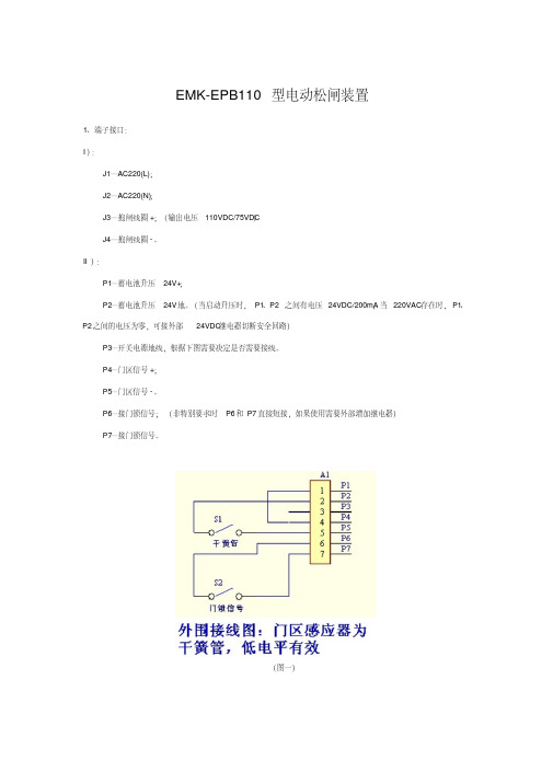
EMK-EPB110型电动松闸装置1、端子接口: I): J1—AC220(L); J2—AC220(N); J3—抱闸线圈+;(输出电压110VDC/75VDC) J4—抱闸线圈-。
II): P1—蓄电池升压24V+; P2—蓄电池升压24V地。
(当启动升压时,P1、P2之间有电压24VDC/200mA,当220VAC存在时,P1、P2之间的电压为零,可接外部24VDC继电器切断安全回路) P3—开关电源地线,根据下图需要决定是否需要接线。
P4—门区信号+; P5—门区信号-。
P6—接门锁信号;(非特别要求时P6和P7直接短接,如果使用需要外部增加继电器) P7—接门锁信号。
(图一) (图二) (图三) (图四) 2、指示灯定义: 输出指示灯定义(从左到右): 第一位蓝色发光(门区指示灯):取消。
第二位红色发光(升压指示灯):当升压时,此灯会变亮,发红光。
反之熄灭,红色LED灯。
第三位绿色发光(运行与低压报警指示灯):当蓄电池未低压报警时,此灯为绿色发光,绿色LED闪烁,当电压低压报警时,此绿色LED则常亮,不闪烁。
第四位黄色发光(充电指示灯):当电池未充满时,此灯会闪烁,发黄光。
当蓄电池充满时,此灯常亮,表示此时电池已经充满。
4、使用方法(使用时请断开所有电源): ①当220VAC存在时,松闸电源不会有升压电压输出,内部电路与外接抱闸电路隔离。
无论按下面板上任何按钮都不会启动升压输出,这样可以避免在220VAC存在时,同时有升压输出的电压与220V整流后的电压一起叠加在抱闸线圈上,这样抱闸线圈或松闸电源存在损坏的隐患。
②、当220VAC不存在时,确保外围接线正确的前提下。
I):当运行绿色“运行指示灯”长灭时,则需要先按下“启动按钮”,松闸电源启动内部电路工作,此时绿色“运行指示灯”会闪烁。
II):非门区位置时,同时按下“启动按钮”和“公共按钮”,松闸电源启动升压电路工作,此时绿色“运行指示灯”会闪烁,“红色升压指示灯”会变亮。

警告感谢您购买了本公司的VICTOR5000电能质量分析仪,为了更好地使用本产品,请一定:——详细阅读本用户手册。
——严格遵守本手册所列出的安全规则及注意事项。
◆违规使用仪器可能导致触电、爆炸或火灾。
★任何情况下,使用本仪器应特别注意安全。
★注意仪器面板及背板的标贴文字及符号。
★使用、拆卸、维修本仪表,必须由有授权资格的人员操作。
★由于仪器原因,继续使用会带来危险时,应立即停止使用,并马上封存,由有授权资格的机构处理。
★仪表及手册上的“”危险标志,使用者必须依照指示进行安全操作。
★★当移除或更换电池或SD卡时,请确保断开测量导线、电流钳、电源适配器并关闭电源。
★电流钳必须与仪表对应连接,否则测试误差可能增大。
★如果电池或SD卡插槽缺失、被破坏或未正确安装,请勿使用仪器。
★任何与本仪器无关的系统安全问题,由该系统的建立、运营商负责。
★出于您的安全考虑,请仅使用随设备所附带的导线和配套附件(符合IEC61010-031(2002)标准)。
当低电压等级的传感器或附件连接至设备时,该低电压等级传感器或附件必须适用于该系统。
★使用前请经常检查测试导线、电流钳和附件处于最佳状况。
任一导线、电流钳或附件,如果绝缘受损(甚至只是部分受损),都必须维修或报废。
★遵从环境状况。
(参阅15.3.1)★若环境需要,请使用个人安全保护设备。
★该仪器必须使用在对地交/直流电压不大于600V的第IV类装置设备(IEC61010-1标准),或使用在电压不大于1000V的第Ⅲ类装置设备。
禁止在更高的电压网络或类型下使用。
★仅使用生产商所提供的电源适配器或电池组,它们具有特定安全等级。
★遵循附件或电流钳的安全级别限制,避免和未使用的终端连接。
★危险电压下某些电流钳不能从暴露的导体上安装或移除。
◆使用和连接步骤:★开启仪器。
★根据所需结果并参照网络类型设置仪器相关参数。
★连接电压测试导线和电流钳到仪器上。
★将地线和(或)中性线的电压测试导线连接到电网的地线和(或)中性线。

中国南方电网有限责任公司110kV 线路保护标准技术标书南方电网设备标准技术标书110kV线路保护编号:0116302052201202中国南方电网有限责任公司2012年02月目次1、总则 (1)2、应遵循的主要标准 (2)3、使用条件 (3)3.1 正常工作大气条件 (3)3.2 贮存、运输环境条件 (4)3.3 周围环境 (4)4、技术要求 (4)4.1 额定电气参数 (4)4.2 技术性能要求 (4)4.3 电磁兼容性能 (6)4.4 绝缘性能 (7)4.5 机械性能 (7)4.6 结构和外观要求 (7)4.7 安全要求 (8)4.8 保护装置继电器设计要求 (8)4.9 屏柜要求 (8)5、功能要求 (14)5.1 基本要求 (14)5.2 开入开出要求 (15)5.3 自动恢复 (16)5.4 自动检测 (16)5.5 定值要求 (16)5.6 事件记录 (17)5.7 装置控制字要求 (17)5.8 装置显示要求 (17)5.9 故障录波 (18)5.10 通信规约 (18)5.11 通讯接口 (18)5.12 时钟与时钟同步 (19)5.13 110kV线路光纤纵联电流差动保护的功能要求 (19)5.14 110kV线路纵联距离保护的功能要求 (19)5.15 相间及接地距离保护的功能要求 (19)5.16 零序电流保护的功能要求 (20)5.17 PT断线过电流保护的功能要求 (20)5.18 重合闸的功能要求 (20)5.19 过负荷保护 (21)5.20 数字接口装置的功能要求 (21)5.21 操作箱(插件)功能要求 (21)5.22 电压切箱(插件)功能要求 (21)6、试验 (22)7、包装、运输、贮存和质量保证 (23)8、双方工作安排 (24)9、订货范围 (25)附件1、技术性能偏差表 (28)附件2、110kV线路保护分项报价设备表 (29)附件3、分项报价备品备件设备表 (31)附件4、专用工具及仪器 (32)附件5、投标者应提交的资料 (33)1、总则1.1 本设备招标技术文件适用于110kV线路微机保护成套装置的功能设计、结构、性能、安装和试验等方面的技术要求。

110kV交联电缆产品介绍一执行标准本产品执行GB/T11017-2002《额定电压110kV交联聚乙烯绝缘电力电缆及其附件》及IEC60840-2004《额定电压30kV(Um= 36kV)以上至150kV(Um= 170kV)挤包绝缘电力电缆及附件——试验方法和要求》等标准。
二型号及名称三电缆额定电压的表示方法电缆的额定电压用U0/U(U m)表示,均为有效值,单位为kV。
即U0/U(U m)=64/110(126)。
U0—电缆设计用的导体与屏蔽或金属套之间的额定工频电压;U —电缆设计用的导体之间的额定工频电压;U m—设备最高电压(使用设备的系统最高电压的最大值)。
五产品规格六使用特性1最高额定温度电缆导体长期允许最高工作温度为90℃,短时过负载最高工作温度为105℃,短路时(短路时间为5S)最高工作温度为250℃。
2安装要求电缆敷设时不受落差限制,敷设时环境温度不低于0℃,如环境温度低于0℃,应对电缆预热。
2.1电缆最小弯曲半径安装时:20D0 ;运行时:15D0注:D0为电缆外径实测值。
2.2电缆安装时的轴向最大允许牵引力T(不考虑转弯处的径向侧压力)导体:T=K×导体截面(kg)式中系数K值为,铜导体K=7kg/mm2,铝导体K=4kg/mm2。
2.3电缆弯曲时的允许最大侧压力PP=T/R≤500(kg/m),式中T为轴向牵引力,R为弯曲半径。
七主要技术性能八电缆结构图九电缆结构参数64/110kV交联聚乙烯绝缘电力电缆十电缆持续载流量1.持续载流量依据IEC60287计算2.安装条件:1)电缆导体工作温度90℃2)环境温度:空气中为40℃, 土壤中为25℃3)土壤热阻系数1.0℃.W4)敷设深度为1000mm5)电缆的轴间距:平行敷设时S=250mm品字型敷设S=D (D为电缆外径)6)频率:50Hz7)负荷率:100%电缆持续载流量表十一载流量修正系数不同空气温度下载流量修正系数不同土壤温度下载流量修正系数不同土壤热阻系数的载流量修正系数十二电缆电性能参数11。

110KV中性点成套装置中性点成套装置也被称为中性点成套保护装置、中性点间隙保护成套装置、变压器中性点间隙接地保护装置、间隙保护等等。
中性点成套装置主要用于110KV、220KV和330KV 变压器中性点过电压保护。
一、中性点成套装置的功能AL-JXB型中性点成套装置专用于电力变压器中性点,以实现变压器中性点接地运行或不接地运行两种不同的运行方式;避免由于系统故障引发变压器中性点电压升高对变压器本体造成损害。
二、中性点成套装置的组成部分1、放电间隙中性点成套装置间隙放电电极主要有两种形式:棒形放电电极和球形放电电极。
球间隙为均匀电场放电电压稳定,分散性小保护性能好、现场调试比较容易,用户可根据自己地区情况现场调试;而棒间隙尖顶特别难对准,所以现场调试难度大。
球间隙采用不锈钢球表面镀银、成本高并且固定要求高,所以许多厂家为降低成本而采用棒间隙,忽略了使用效果。
2、电流互感器电流互感器选用:采用环氧树脂浇注的干式电流互感器。
电流互感器装在不锈钢箱体里,不受环境气候影响,使用寿命长,使保护不会出现误动或拒动且稳定可靠。
3、避雷器避雷器作为中性点成套装置的可选项.4、隔离开关隔离开关包括手动隔离开关和电动隔离开关两种。
5、操作机构中兴点成套装置的操作机构也是选配项,主要包括电动操作机构和手动操作机构两种。
6、底座另外中性点成套装置也可选配避雷器在线监测器、支柱等等。
三、设备接线原理图六、中性点成套装置安装要求1、设备可利用底座的4个安装孔进行吊装,不得把吊绳捆绑在瓷柱上,防止损坏设备。
2、固定操作机构的槽钢支架和由操作机构到隔离开关导电杆转轴的钢管,不在本装置的供货范围内。
均由安装单位现场制作,长度、尺寸现场确定。
3、设备应可靠接地。
4、产品的外形及尺寸以实际供货为准。
5、隔离开关的安装可参照附件GW8系列中性点隔离开关的安装说明进行。
上海昌开电器有限公司。
本系列产品适用于交流,主电路额定工作电压至,额定工作电流至的电力系统中。
供销远距离接通和分断电路及频繁地起动的控制交流电动机之用,并于适当的保护装置组成电磁起动器,特别适宜于组成矿用隔爆型电磁起动器,也适宜于用来切换电容器组。
本产品在660~1140V 的电力系统、380V 重负荷场合及使用环境恶劣的场合均有明显的优越性。
50Hz 1140V 630A 正常工作条件和安装条件结构特点□ □ 海拔:安装地点的海拔不超过2000m ;□ 湿度:最高温度为+40℃时,空气的相对湿度不超过50%,在较低的温度下允许有较高的湿 度,例如20℃时达90%。
对由于温度变化偶尔产生的凝露应采取措施。
□ 污染等级:3;□ 安装类别:Ⅲ;□ 安装:安装面与垂真面倾斜度不超过±15度;□ 冲击和振动:无显著冲击、震动和摇动的地方;□ 运输和储存:-25℃~+55℃,在短时间内(24h )可达+70℃。
周围空气温度:-5℃~+40℃;且24h 内的平均温度不超过+35℃;□ 室、框架及基座、电磁机构、转动部分、整流装置及辅助触头组等组成。
□ 动触头部件通过波纹管连接杂在真空灭弧室中,保证了动触头做轴向转动时,灭弧室中真空度 保持不变,所以通常在电弧第一次过零时就被熄灭,燃弧时间一般小于10ms 。
本产品主触头密封在真空容器,(称真空灭弧室),以真空为熄弧介质。
产品由真空灭弧产品概述选型指南CKJ5系列交流真空接触器039图2 CKJ-80、125、160的安装尺寸图1 CKJ5型外形尺寸及安装尺寸表1动作特性:在以上电压下,正常周围空气温度下,接触器在75Us~110Us 内可靠吸合,释放电压为75Us~10Us 。
外形及安装尺寸表2订货须知定货时必须说明:接触器的型号、名称、额定电压、额定电流;b 、操作回路的额定控制电源电压及频率;c 、定货台数;□ 备件数量,例如真空灭弧室的数量。
□ 定货举例:CKJ 交流真空接触器,额定控制电源电压50Hz ,220V ,100台、真空灭弧室150只。
Table Of ContentsTable Of Contents . . . . . . . . . . . . . . . . . . . . . . . . . . . . . . . . . . . . . . . . . . . . . . . . . . . . . . . . . . . . . . . . . . . . . . . .2 Abstract . . . . . . . . . . . . . . . . . . . . . . . . . . . . . . . . . . . . . . . . . . . . . . . . . . . . . . . . . . . . . . . . . . . . . . . . . . . . . . .3 Introduction . . . . . . . . . . . . . . . . . . . . . . . . . . . . . . . . . . . . . . . . . . . . . . . . . . . . . . . . . . . . . . . . . . . . . . . . . . . .4 Lead Free Legislation . . . . . . . . . . . . . . . . . . . . . . . . . . . . . . . . . . . . . . . . . . . . . . . . . . . . . . . . . . . . . . . .5 European Union Directive . . . . . . . . . . . . . . . . . . . . . . . . . . . . . . . . . . . . . . . . . . . . . . . . . . . . . . . . . . . . .5 Japanese Ministry of Trade . . . . . . . . . . . . . . . . . . . . . . . . . . . . . . . . . . . . . . . . . . . . . . . . . . . . . . . . . . . .5 US Legislation . . . . . . . . . . . . . . . . . . . . . . . . . . . . . . . . . . . . . . . . . . . . . . . . . . . . . . . . . . . . . . . . . . . . .5 Bourns Commitment to Lead Free Components . . . . . . . . . . . . . . . . . . . . . . . . . . . . . . . . . . . . . . . . . . . . . .5 Bourns® Lead Free Surface Mount Multifuse® Polymer PTC Product Portfolio . . . . . . . . . . . . . . . . . . . . . . . . . . . . .6 Category 2 Typical Coating Durability for Non-Tin and Non-Tin Lead Finishes . . . . . . . . . . . . . . . . . . . . . . . . .6 Category 3 Typical Coating Durability Default for Tin and Tin Lead Finishes . . . . . . . . . . . . . . . . . . . . . . . . . .6 Multifuse® Surface Mount Component Terminations . . . . . . . . . . . . . . . . . . . . . . . . . . . . . . . . . . . . . . . . . .7 Part Number Explanation . . . . . . . . . . . . . . . . . . . . . . . . . . . . . . . . . . . . . . . . . . . . . . . . . . . . . . . . . . . . .7 Bourns® Lead Free Radial Multifuse® Polymer PTC Product Portfolio . . . . . . . . . . . . . . . . . . . . . . . . . . . . . . . . . . . .8 Part Number Explanation . . . . . . . . . . . . . . . . . . . . . . . . . . . . . . . . . . . . . . . . . . . . . . . . . . . . . . . . . . . . .8 Improved Heat Resistance . . . . . . . . . . . . . . . . . . . . . . . . . . . . . . . . . . . . . . . . . . . . . . . . . . . . . . . . . . . .9 Recommended Reflow Profiles . . . . . . . . . . . . . . . . . . . . . . . . . . . . . . . . . . . . . . . . . . . . . . . . . . . . . . . . .9 Lead Free Solder Paste . . . . . . . . . . . . . . . . . . . . . . . . . . . . . . . . . . . . . . . . . . . . . . . . . . . . . . . . . . . . . . .9 Cross-Sections of Fillet Shaped Solder Joints . . . . . . . . . . . . . . . . . . . . . . . . . . . . . . . . . . . . . . . . . . . . . . .10 Test Results . . . . . . . . . . . . . . . . . . . . . . . . . . . . . . . . . . . . . . . . . . . . . . . . . . . . . . . . . . . . . . . . . . . . . . . . . . .11 Terminal Strength Test Comparison Between Lead and Lead Free Plated Products . . . . . . . . . . . . . . . . . . . . .11 Terminal Strength Test of Lead Free Plated Products after Steam Aging . . . . . . . . . . . . . . . . . . . . . . . . . . . .12 Tin Whisker Growth Accelerated Test . . . . . . . . . . . . . . . . . . . . . . . . . . . . . . . . . . . . . . . . . . . . . . . . . . . .13 Solderability . . . . . . . . . . . . . . . . . . . . . . . . . . . . . . . . . . . . . . . . . . . . . . . . . . . . . . . . . . . . . . . . . . . . .14 Additional Testing . . . . . . . . . . . . . . . . . . . . . . . . . . . . . . . . . . . . . . . . . . . . . . . . . . . . . . . . . . . . . . . . .15 Conclusion . . . . . . . . . . . . . . . . . . . . . . . . . . . . . . . . . . . . . . . . . . . . . . . . . . . . . . . . . . . . . . . . . . . . . . . . . . . .16AbstractIn today’s environmentally conscious world there is a strong movement away from the use of lead in favor of alternative products.This is happening across all industry sectors.We have been introduced to lead free paint, lead free castings,lead free fuel and many other lead free products.As electronic goods become disposable commodities the electronics sector has become the principal driver of this trend.The majority of electronic companies are now evaluating lead free solders.Manufacturers are producing lead free components and the sector as a whole is moving very quickly to lead free electronic devices.Bourns® Multifuse® Polymer PTC product line meets the requirements of the global community with a product family of lead free surface mount products.In terms of Bourns general strategic policy,the movement to a lead free surface mount component is consistent with our overall environmental policy.Our principal manufacturing and design site for Bourns® Multifuse® products is ISO 14001 certified,reflecting our strong commitment to the environment.The effective introduction of the ISO 14001 standard has allowed Bourns to achieve reductions in both environmental risk and costs.Achieving this voluntary registration demonstrates Bourns pledge to the global community and illustrates company environmental awareness.IntroductionThe development of lead free surface mount Bourns® Multifuse® Polymer PTC devices involved converting the tin lead plating on product terminations to a lead free alternative. Strict criteria were developed to guide the selection of the optimum material.1.The lead free termination should have no adverse effect on the ability of the component tosolder to an interconnecting substrate.2.The strength of the bond between the terminal and the substrate must be maintained at theexisting high level,significantly above the industry standard (JIS-C-6429).3.The devices must be compatible with traditional tin lead solders as well as lead free solders.4.The devices must have the ability to withstand the peak temperature of the standard reflowtemperature profile of both types of solder,typically 245 °C for tin lead and 260 °C for leadfree.5.The components should be exposed to the industry accepted accelerated steam aging process(Reference J-STD-002A) to evaluate the long-term durability and reliability of the lead freeterminations.6.Storage under normal conditions (40 °C Max 75 % RH Max) should have no adverse effecton the solderability of the device.7.Whisker growth should be evaluated by an industry accepted accelerated growth testprocedure.8.The components must be qualified to Bourns internal and independent agency standards(UL,CSA and TÜV).9.The product must maintain its commercial competitive advantage.The tin lead terminations of our 1812 (MF-MSMD) and 1210 (MF-USMD) product families have been replaced with an electroless nickel immersion gold (ENIG) termination that maintains the high performances and quality standards of the existing Bourns® Multifuse® product family. Subsequently, Bourns has released a 2018 (MF-SMDF) and a 1206 (MF-NSMF) product family with ENIG terminations. A second option of a 100 % tin termination is also available on the product families referenced above. The terminations of the larger 3425 and 2920 (MF-SM) product families are only available with 100 % tin plated terminations.This report details the procedures used to ensure the above criteria were met. The first section outlines the current legislation driving the trend towards lead free products. A brief summary of the European, US, and Japanese lead free legislation is outlined for general information (and is not intended as legal advice). The test and results section details the methods used to ensure the components meet or exceed the relevant industry standards as well as Bourns own internal standards developed over 50 years of component manufacturing and design. A complete section is dedicated to solderability. The objective of this section is to clearly outline how solderability is categorized. Finally the conclusion section outlines the findings and recommendations of our evaluation.Lead Free Legislation as of 2004EUROPEAN UNION DIRECTIVEIn parallel to the drive initiated by environmentally conscious corporations,legislation has been drafted to accelerate the change to non-toxic products. Thislegislation will directly affect the solder, electronic component and assemblyindustries. The European Union’s directive, the Reduction on Hazardous Substances(RoHS) sets phase-out dates for the use of lead (Pb) and several other materials usedin electronic products. The RoHS requires that on July 1, 2006, the targeted materials,including lead may no longer be used unless there is an exemption provided in therule. This legislation has a direct impact on the type of solder and components thatcan be used in electronic devices.JAPANESE MINISTRY OF TRADEThe Japanese Ministry of Trade (MITI) has drafted a recycling law for electricalappliances. This does not yet include a phase-out of the use of lead, but it is expectedto do so in the near future. The recycling law will require consumer and businessusers of electrical appliances to return end-of-life goods to retailers or localauthorities for recycling. A key factor will be the elimination of lead based products.US LEGISLATIONAlthough there is no federal legislation yet in the US, there are a number of stateselectronics recycling initiatives to consider. In addition, the Environmental ProtectionAgency (EPA) has recently proposed a crackdown on lead emissions frommanufacturing plants. This action may speed the industry to embrace lead free soldermuch more quickly than originally planned.BOURNS COMMITMENT TO LEAD FREE COMPONENTSThe remainder of the report outlines the specification of Bourns® surface mountMultifuse® Polymer PTC devices and the procedure used to qualify these devices. Reliable Electronic SolutionsBourns® Lead Free Surface Mount Multifuse® Polymer PTC Product PortfolioBourns® Multifuse® Polymer PTC lead free surface mount components’ (MF-SMDF, MF-MSMF, and MF-NSMF) standard metal termination finish is electroless nickel immersion gold (ENIG). The finish gives the components long shelf life and the precious metal topcoat provides excellent electrical connectivity. The ENIG finished components fully comply with the solderability characteristics defined in the joint industry standard ANSI/J-STD-002 Category 2.Bourns offers an alternative electroless 100 % tin (Sn) termination finish to the standard ENIG finish. This option is available for applications requiring the soldering characteristics of ANSI/J-STD-002, Category 3.CATEGORY 2 TYPICAL COATING DURABILITY FOR NON-TIN AND NON-TIN LEAD FINISHESThis category is intended for surfaces finished with other than Sn or Sn/Pb coatings that will be soldered after an extended time from the time of testing. Standard Bourns® Multifuse® Polymer PTC surface mount products have an ENIG coated terminal consistent with this category. These parts were tested and found to comply with the tests and procedures outlined in Category 2.CATEGORY 3 TYPICAL COATING DURABILITY DEFAULT FOR TIN AND TIN LEAD FINISHESA category intended for surfaces finished with Sn or Sn/Pb coatings, which will be soldered after an extended storage from the time of testing. The Bourns® Multifuse® Polymer PTC devices with an optional Sn finish fall into this category and all products with the optional Sn finish meet or exceed the requirements of this category.BOURNS® MULTIFUSE® SURFACE MOUNT COMPONENT TERMINATIONSPART NUMBER EXPLANATIONMF-SM150/33-2-99MF . . . . . . . . . .Bourns® Multifuse® Product DesignatorSM . . . . . . . . . .The letters between MF and the digits represent the product series,i.e.MSMD and MSMF 1812,USMD1210,NSMF 1206 and SMDF 2018.SM is common for all Metal (Sn coated Brass) framedesigns;no size distinction150 . . . . . . . . . .The digits following the product designator represent the hold current of the device for example150 = 1.5 amps or 110 = 1.10 amps/33 . . . . . . . . . . .Indicates high voltage model-2 . . . . . . . . . . . .Packaging option –2 = Tape & Reel –1 = Bulk Packaging-99 . . . . . . . . . .Lead free option for MF-SM products.For the lead free version of the MF-MSMD and MF-USMDproducts,please see MF-MSMF,MF-NSMF and MF-USMF*.MF-SM (Metal Frame)Product DesignSn or Sn/Pb Termination.MF-MSMD Product Design Sn/Pb Termination MF-SMDF,MF-MSMF and MF-NSMF Product Design ENIG TerminationBourns® Lead Free Radial Multifuse® Polymer PTC Product PortfolioThe majority of Bourns® Radial Multifuse® Polymer PTC products are lead free as standard.The low voltage products (60 V or below) use Sn/Pb solder to attach the metal body to thePTC body. To order these products as lead free simply place a -99 at the end of the partnumber and the lead will be attached by a Sn/Ag solder. (All radial products manufacturedafter March 2005 will be lead free as standard so the need to add a -99 at the end of the lowvoltage product name will no longer be necessary.)The MF-RX/72, MF-RX/250 and MF-R/600 product families are all lead free as standard.PART NUMBER EXPLANATIONMF-R110-2-99MF . . . . . . . . . .Bourns® Multifuse® Product DesignatorR . . . . . . . . . . .The letters between MF and the digits represent the product series,the radial series R or the RX series 012 . . . . . . . . . .The digits following the product designator represent the hold current of the device for example110 = 1.10 amps/250 . . . . . . . . ._ = Standard rated part,/250 = 250 Volt interrupt rated part-2 . . . . . . . . . . . .Packaging option –2 = Tape & Reel –1 = Bulk Packaging-99 . . . . . . . . . .Lead Free Option* The 72V rated MF-RX/72 product is the lead free equivalent of the MF-RX product.IMPROVED HEAT RESISTANCEThe new lead free plated Bourns® Multifuse® Polymer PTCs have the ability to be reflow soldered with both lead and lead free solder pastes (e.g. Sn/Ag/Cu). Both types of solder paste require the components to withstand reflow temperatures of 245 °C and 260 °C.RECOMMENDED REFLOW PROFILESLEAD FREE SOLDER PASTEBourns® Multifuse® Polymer PTCs can be reflow soldered with the majority of commercially available lead free solder pastes. Bourns refers to 96.5/3.5 Tin/Silver as lead free solder paste. 96.5/3.5 Tin/Silver solder paste was used for all lead free testing documented in this paper. For information concerning other specific PreheatingT e m p e r a t u r e (°C )Time (sec)160 ~ 22012010 ~ 20Soldering Cooling30025020015010050grades of lead free solder pastes please contact your local Bourns representative.CROSS-SECTIONS OF FILLET SHAPED SOLDER JOINTS Model TerminationBondingSolder Paste MF-MSMD Sn/Pb solder paste MF-MSMF96.5/3.5 Tin/Silver solder pasteTest ResultsTERMINAL STRENGTH TEST COMPARISON BETWEEN LEAD AND LEAD FREE PLATED PRODUCTSBoth tin lead and lead free plated Bourns® Multifuse® Polymer PTCs form solder joints with terminal strength values in excess of the specification of the JIS-C-6429 standard (also used in AEC-Q200 Rev B). Thecastellated design of the lead free plated Polymer PTCs show further improved terminal strength of the solder joints when compared to the tin lead plated products.TERMINAL STRENGTH AFTER REFLOW USING LEAD FREE SOLDER···> Parts reflowed using a lead free 96.5/3.5 solder paste ···> Parts reflowed using the recommended reflow profileTERMINAL STRENGTH AFTER REFLOW USING Sn/Pb SOLDER25.020.015.010.05.00.0Tin Lead Plating Electroless Gold Electroless TinShear test123No.of ReflowsJIS Standard T e r m i n a l S t r e n g t h (K g .f )25.020.015.010.05.00.0Tin Lead Plating Electroless Gold Electroless TinShear test 123No.of ReflowsT e r m i n a l S t r e n g t h (K g .f )JIS StandardTERMINAL STRENGTH TEST OF LEAD FREE PLATED PRODUCTS AFTER STEAM AGINGThe electroless gold plated Bourns® Multifuse® Polymer PTCs show no significant reduction in the terminal strength of the solder joints after being subjected to a 72-hour steam age test (85 °C, 85 % humidity).TERMINAL STRENGTH AFTER 72 HOUR 85 °C, 85 % STEAM AGING AND REFLOWED USING Sn/Pb SOLDER···> Parts reflowed using a lead free 96.5/3.5 solder paste ···> Parts reflowed using the recommended reflow profileTERMINAL STRENGTH AFTER REFLOW USING Sn/Pb SOLDER 25.020.015.010.05.00.0Electroless GoldShear test123No.of ReflowsJIS StandardT e r m i n a l S t r e n g t h (K g .f )20.015.010.05.00.0Electroless GoldShear test123No.of ReflowsJIS StandardT e r m i n a l S t r e n g t h (K g .f )TIN WHISKER GROWTH ACCELERATED TESTBourns® Multifuse® Polymer PTC lead free surface mount components standard metal termination finish is electroless nickel immersion gold (ENIG). However, since components may also be supplied with a 100 % tin (Sn) finish, tests must be performed to measure the propensity of the tin plating to grow whiskers.Two sets of tests were carried out to accelerate tin whisker growth:···> Temperature cycle test: 500 cycles, 1 cycle= [-35 °C 7 min, 23 °C 5 min, 125 °C 7 min, 23 °C 5 min]···> Temperature humidity: 85 °C , 85 % RH, 500 hoursThe tests match the requirements in the SONY SS-00254 method.Microscopic and scanning electron microscopic inspections following the tests showed no significant growth of tin whiskers in any Sn finished Bourns® Multifuse® Polymer PTC surface mount components.Bourns® Multifuse® Polymer PTC components are plated with a white immersion tin process. This process has gained widespread acceptance as a coating. Some of the advantages of white tin include superior solderability, long shelf life and reworkability. The coating can withstand multiple heat cycles and can be used with all of the leading industry solder profiles. Immersion white tin is formulated to create a fine, dense grain structure that is stable and works to suppress the growth of an intermetallic layer. This distinguishes it from traditional tins, which have a porous structure that is unstable and insufficient to suppress the intermetallic layer. This fine grain structure allows immersion white tin to resist the dendritic growth or "tin whiskers" that can be a problem for other tins. A component coated with immersion white tin will have a solderable shelf life of more than one year. Bourns® PTCs are manufactured with an annealed process stepWhite Tin Gray TinFine Grain Hexagonal CrystalLarge Grain Orthorhombic Crystaldesigned to prevent tin whisker growth.SOLDERABILITYTo evaluate the durability and reliability of any electronic component termination finish, solderability and steam age tests are conducted on the component. Bourns® Multifuse® Polymer PTC Components with the ENIG finish and with the 100 % Sn finish have undergone extensive solderability testing. All of Bourns®Multifuse® Polymer PTC lead free surface mount components have been found to be compliant with the Joint Industry Standard, J-STD-002A. The title of the standard is Solderability Tests for Component Leads, Terminations, Lugs, Terminals and Wires. The EIA soldering Technology Committee (STC) and the Component and Wire Solderability Specification Task Group of IPC developed the joint industry standard to establish procedures to assess the solderability of electronic components.The tests outlined in the standard evaluate the resistance of the surface finish of the termination to dissolution of metallization; determination is made to verify that the metallized terminations will remain intact throughout the assembly soldering process. Compliance to the standard also indicates that subsequent storage will have no adverse effect on the ability of the components to solder to an interconnecting substrate. Steam age testing enables evaluation of the storage life capability of the components. Steam aging is used to accelerate the degradation of the metal surfaces in a similar manner to natural aging. The degradation mechanisms of surface oxidations and intermetallic growth are both enhanced by the heat and humidity of steam. The standard outlines a number of steam aging categories for a range of component leads and terminations. In this regard two categories apply to Bourns® Multifuse® Polymer PTC lead free surface mount components:Category 2 Typical Coating Durability for Non-Tin and Non-Tin Lead Finishes.This category is intended for surfaces finished with other than Sn or Sn/Pb coatings, which will be soldered after an extended time from the time of testing. Bourns® standard Multifuse® Polymer PTC surface mount products have an ENIG coated terminal so they fall into this category. These parts have been tested and have been found to comply with the tests and procedures outlined for the category.Category 3 Typical Coating Durability Default for Tin and Tin Lead Finishes.A category intended for surfaces finished with Sn or Sn/Pb coatings, which will be soldered after an extended storage from the time of testing. The Bourns® Multifuse® Polymer PTC devices with the optional Sn finish fall into this category; all products with the optional Sn finish meet or exceed the requirements of the category.ADDITIONAL TESTINGIn addition to the solderability tests, the components have been fully tested to our own internal qualification tests and the independent agency tests outlined below. Bourns® Multifuse® Polymer PTC surface mount components with a Sn finish have also been subjected to a tin whisker accelerated growth test procedure. They have been subjected to temperature cycling tests and constant temperature/humidity test procedures and in each case complied with or exceeded the existing industry standards.ConclusionBourns continues to demonstrate its environmental consciousness to the greater community by developing more environmentally friendly products. This document highlights the lead free construction of the new surface mount Bourns® Multifuse® Polymer PTCs and their ability to be assembled with both lead and lead free solder pastes and reflow profiles. The tests completed ensure the components meet the guidelines for suppliers transitioning to lead free components as outlined in the EMS Forum on Lead Free PCB Assembly. In general this document highlights the continued dedication of Bourns to produce robust and reliable components without compromising either performance or reliability.ReferencesThis document was made with reference to the following documents:• Sony SS-00254• EMS Forum – Guidelines for Suppliers Transitioning to Lead Free Components,Rev 1.0• IBM Server & Storage Systems Environmental Requirements for Purchasing Electronic Components(including restriction on hazardous materials RoHS)• Directive 2002/95/EC of the European Parliament and of the Council of January 27,2003 on therestriction of the use of certain hazardous substances in electrical and electronic equipment"Bourns" and "Multifuse" are registered trademarks of Bourns, Inc. in the U.S. and other countries.COPYRIGHT© 2004, BOURNS, INC. • 04/04 • e/MF0406。
EPJ3K~5K-110电力逆变电源系统技术手册
一、简介
该电源采用美国INTEL公司16位专用微处理芯片控制,主电路采用日本三菱公司最先进的智能功率IGBT模块(IPM),具有可靠性高、保护功能全、波形失真小、价格低廉等优点。
二、应用
该系列正弦波逆变电源输入直流电压为110V DC,输出为220V AC。
主要为发电厂、电力系统、铁路等重要场合提供不间断电力。
三、运行模式
模式 1.在线运行模式:在许多重要负载场所,要求给设备提供的电力电压稳定、畸变小、并在市电异常时实现零时间转换,这就要求逆变电源长期连续运行。
使用方法是将直流接入逆变电源直流输入端,交流输出接入负载,该模式下逆变电源具有旁路功能,即一旦直流电源(电池屏)电压异常或逆变电源出现故障,将自动切换到交流旁路或另一台逆变电源上。
模式 2.热备份运行模式:在许多场合,由于直流动力容量有限或整流机(充电机)功率较小,若长时间使用在线逆变有可能会使蓄电池亏电最终导致停电事故,为提高供电可靠性,逆变电源可处于市电旁路工作,一旦市电出现异常,即迅速切换至逆变电源供电。
由于切换时间极短(≤5ms),不会给负载(如计算机等)造成影响。
使用方法是将市电接入“市电输入”端子,逆变电源将自动进入热备份运行模式。
注:本机运行在□模式1 □模式2
四、安装步骤及使用方法
1、开箱时请检查箱体是否有损坏情况,若箱体有明显变形,请立即与供应商联系。
2、确认前面板上开关处于“关”位置。
3、按逆变器后面板标明接线。
4、若逆变电源工作在模式1时,应先开逆变电源,再接入市电;若逆变电源工作在模式2
时,应先接市电,后开逆变电源。
5、将前面板开关置于“开”位置,即可投入使用。
6、逆变电源工作在模式1时若出现故障,则切换至市电工作状态,这时,电源已封锁逆
变部份工作。
应断开市电,排除逆变电源故障后重新开启逆变电源,再接入市电,使逆变电源恢复正常。
五、注意事项
1、请勿将直流输入和交流输出接反。
2、输入直流电压低于95V DC时逆变电源将自动关闭。
同时电池电压异常指示灯常亮,当电
池电压恢复至100V DC或以上时,逆变电源将再次起动。
设置回差电压是为了防止系统在欠压点附近振荡。
3、当直流电压高于135V DC时,逆变电源将过压保护,此时电池电压异常指示灯闪烁,同
时交流输出将关闭,此时将切换至旁路或另一台逆变电源供电。
电池电压即直流输入电压异常时的保护点电压及回差电压用户可自行调整,如逆变电源应用于太阳能或风力发电场所,由于电池处于循环使用而不是浮充状态,因此其回差电压必须加大,以防蓄电池过放电。
4、当输出过载时,过载指示灯亮并关闭输出;当输出短路时,过载指示灯闪烁并关闭输
出。
5、感性负载时请考虑功率因素,非线性负载(如计算机、工控机)时请考虑
起动冲击。
带这两种负载时,逆变电源均需降额使用。
6、本机采用智能风扇,机内温度达55℃时开始运转。
附:技术指标
保护功能说明备注
输出过载保护负载功率超过120%时,10秒钟延时后将关闭输出
输出短路保护输出如果短路,逆变电源将自动关闭
需关机才能复位
输入反接保护输入逆变器的直流电压极性如果接反,逆变电源将自动关闭
输入欠压保护输入Dc<95V时,逆变电源将自动关闭
输入过压保护输入Dc>135V时,逆变电源将自动关闭
过热保护逆变电源机箱内温度超过75℃时,输
出将自动关闭
待输入电压或温度恢复正
常后输出将自动恢复。