ESP8266芯片规格书
- 格式:pptx
- 大小:299.51 KB
- 文档页数:15
规格书版本1.02015年8月23日免责申明和版权公告本文中的信息,包括供参考的URL地址,如有变更,恕不另行通知。
文档“按现状”提供,不负任何担保责任,包括对适销性、适用于特定用途或非侵权性的任何担保,和任何提案、规格或样品在他处提到的任何担保。
本文档不负任何责任,包括使用本文档内信息产生的侵犯任何专利权行为的责任。
本文档在此未以禁止反言或其他方式授予任何知识产权使⽤许可,不管是明示许可还是暗示许可。
Wi-Fi 联盟成员标志归Wi-Fi 联盟所有。
文中提到的所有商标名称、商标和注册商标均属其各自所有者的财产,特此声明。
注意由于产品版本升级或其他原因,本手册内容有可能变更。
深圳市安信可科技有限公司保留在没有任何通知或者提示的情况下对本手册的内容进行修改的权利。
本手册仅作为使用指导,深圳市安信可科技有限公司尽全力在本手册中提供准确的信息,但是深圳市安信可科技有限公司并不确保手册内容完全没有错误,本手册中的所有陈述、信息和建议也不构成任何明示或暗示的担保。
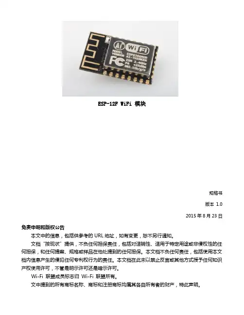
目录1. 产品概述 (2)1.1. 特点 (3)1.2. 主要参数 (4)2. 接口定义 (5)3. 外型与尺寸 (7)4. 功能描述 (9)4.1. MCU (9)4.2. 存储描述 (9)4.3. 晶振 (9)4.4. 接口说明 (10)4.5. 最大额定值 (11)4.6. 建议工作环境 (11)4.7. 数字端口特征 (11)5. RF 参数 (12)6. 功耗 (13)7. 倾斜升温 (14)8. 原理图 (15)9. 产品试用 (16)1.产品概述ESP-12F WiFi 模块是由安信可科技开发的,该模块核心处理器ESP8266 在较小尺寸封装中集成了业界领先的Tensilica L106 超低功耗32 位微型MCU,带有16 位精简模式,主频支持80 MHz 和160 MHz,支持RTOS,集成Wi-Fi MAC/ BB/RF/PA/LNA,板载天线。


免责申明和版权公告本文中的信息,包括供参考的URL地址,如有变更,恕不另行通知。
文档“按现状”提供,不负任何担保责任,包括对适销性、适用于特定用途或非侵权性的任何担保,和任何提案、规格或样品在他处提到的任何担保。
本文档不负任何责任,包括使用本文档内信息产生的侵犯任何专利权行为的责任。
本文档在此未以禁止反言或其他方式授予任何知识产权使用许可,不管是明示许可还是暗示许可。
Wi-Fi联盟成员标志归Wi-Fi联盟所有。
文中提到的所有商标名称、商标和注册商标均属其各自所有者的财产,特此声明。
目录1简介5 2技术概述6 3特征7 4应用图表8 5超低能耗技术95.1最大集成度9 6ESP8266 的应用主体10 7规格117.1功耗117.2射频规格12 8CPU、存储器和接口138.1CPU 138.2存储控制器138.3AHB和AHB模块138.4接口148.4.1 主SI/SPI控制(可选)148.4.2 通用 IO 158.4.3 数字IO 管脚15 9固件和软件工具开发包179.1特征17 10电源管理19 11时钟管理2011.1高频时钟2011.2外部参考要求2112无线电接收器2212.1频道频率2212.2 2.4GH Z接收器2212.3 2.4GH Z发射器2312.4时钟生成器23附 QFN32封装尺寸图241简介乐鑫智能互联平台——ESCP拥有高性能无线SOC,给移动平台设计师带来福音,它以最低成本提供最大实用性,为WiFi功能嵌入其他系统提供无限可能。
图1:ESP8266 时钟结构图2技术概述ESP8266是一个完整且自成体系的Wi-Fi网络解决方案,能够搭载软件应用,或通过另一个应用处理器卸载所有Wi-Fi网络功能。
ESP8266在搭载应用并作为设备中唯一的应用处理器时,能够直接从外接闪存中启动。
内置的高速缓冲存储器有利于提高系统性能,并减少内存需求。
另外一种情况是,无线上网接入承担Wi-Fi适配器的任务时,可以将其添加到任何基于微控制器的设计中,连接简单易行,只需通过SPI/SDIO接口或中央处理器AHB 桥接口即可。
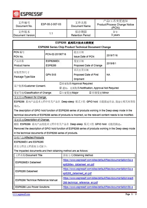
文件编号Document No.ESP-00-2-007-03文件名称Document Name产品/工艺变更通知Product/Process Change Notice(PCN)文件版本Document Version1.1保存期限Retention Period3年3 yearsESP8266 系列芯片技术文档变更ESP8266 Series Chip Product Technical Document ChangePCN编号PCN No.PCN-02-20190716提出日期Issue Date of PCN2019/7/16产品名称Product Name ESP8266EXESP8285变更日期Proposed Date of Change2019/8/1封装类型/尺寸Package Type/Size QFN 5X5首次出货日期Proposed Date of FirstShipmentNA客户批准/Customer Consent: 需要批准/Approval Required通知,无需批准/Notification, Approval Not Required变更等级/Classification of Change: 主要变更/Major 轻微变更/Minor变更原因/Reason for Change:ESP8266 系列产品技术文档中有关产品在Deep-sleep 模式下的GPIO hold 功能描述有误,故进行相关内容的修改。
The description of GPIO hold function of ESP8266 series of products working in the Deep-sleep mode in the technical documents of ESP8266 series of products is incorrect, so the relevant content needs to be modified.变更描述/Description of Change:删除ESP8266 系列产品的技术文档中有关产品在Deep-sleep 模式下的GPIO hold 功能的描述。
ESP8266 Phy Init Bin重要参数配置说明版本 1.0乐鑫信息科技版权所有 © 2018关于本⼿手册本⽂文档主要对ESP8266 phy init bin 的重要参数配置情况进⾏行行了了说明。
发布说明⽇日期版本发布说明2018.12V1.0⾸首次发布。
⽂文档变更更通知⽤用户可通过乐鑫官⽹网订阅⻚页⾯面https:///zh-hans/subscribe订阅技术⽂文档变更更的电⼦子邮件通知。
证书下载⽤用户可通过乐鑫官⽹网证书下载⻚页⾯面https:///zh-hans/certificates下载产品证书。
⽬目录..............................................................................................1.ESP8266 Phy Init Bin 结构说明 1.................................................................................................2.ESP8266 Phy Init Bin 校验位 2..............................................................................................3.ESP8266 Phy Init Bin 版本信息 3.................................................................................................................................4.晶振选择 4................................................................................................................5.6 档 TX Power 设置 5.....................................................................................................6.不不同速率配置的 TX Power 6................................................................................................................7.TX Power 限制设置7......................................................................................................7.1.TX Power 可配的限制值范围 77.2.TX Power 限制参数说明 7............................................................................................................................................................................................................................................8.RF ⾃自校准91. ESP8266 Phy Init Bin 结构说明 1.ESP8266 Phy Init Bin结构说明ESP8266 phy init bin 由 128-byte 的phy init data 构成,如表1-1所示:表 1-1. ESP8266 Phy Init Bin 结构说明名称⼤大⼩小phy init data128 bytes2. ESP8266 Phy Init Bin 校验位 2.ESP8266 Phy Init Bin 校验位ESP8266phy init bin 校验位存于phy init data的 byte 0 中,参数为Init_bin_magic,默认值为 0x5。

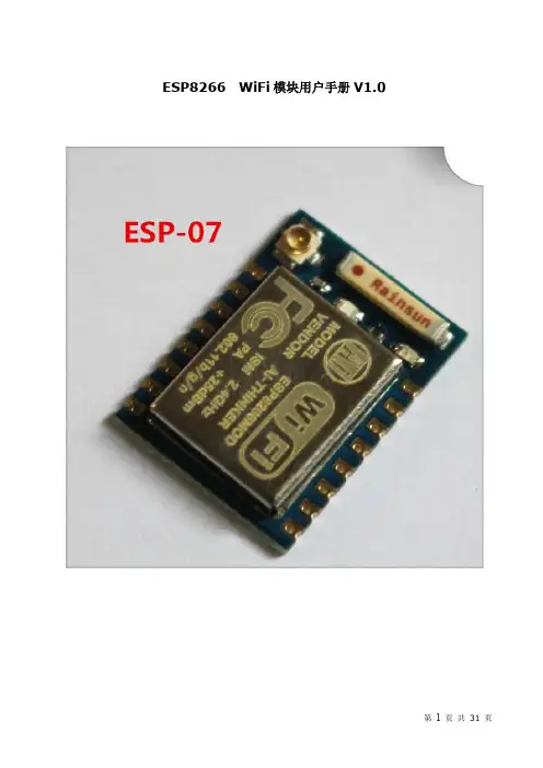
E S P8266-08-W iF i模块用户手册V1.0ESP8266 WiFi模块用户手册V1.0目录术语和缩写 (4)1.产品简介 (5)1.1.概述 (5)1.1.1产品特性 (5)1.1.2模块封装 (6)1.1.3模块基本参数 (6)1.2.硬件介绍 (7)1.3.功耗 (10)1.4.射频指标 (11)1.5.尺寸 (13)1.6.WiFi 天线 (14)1.7.推荐炉温曲线 (14)2.功能描述 (15)2.1.主要功能 (15)2.2.工作模式 (15)2.3.应用领域 (16)2.4.AiCloud (16)3.全功能测试版介绍 (17)3.1.测试步骤 (18)3.2.基础AT指令 (22)3.2.1 测试AT (22)3.3.WiFi功能AT指令 (22)3.3.1 选择WiFi应用模式:AT+CWMODE (22)3.3.2列出当前可用接入点:AT+CWLAP (23)3.3.3 加入接入点:AT+CWJAP (23)3.3.4 退出接入点:AT+CWQAP (23)3.3.5设置AP模式下的参数:AT+CWSAP (24)3.4.TCPIP AT指令 (25)3.4.1建立TCP/UDP连接:AT+CIPSTART (25)3.4.2获得TCP/UDP连接状态:AT+CIPSTATUS (25)3.4.3启动多连接:AT+CIPMUX (26)3.4.4发送数据:AT+CIPSEND (27)3.4.5关闭TCP/UDP连接:AT+CIPCLOSE (27)3.4.6获取本地IP地址:AT+CIFSR (28)3.4.7配置为服务器: (29)3.4.8选择TCPIP应用模式:AT+CIPMODE (32)3.4.9设置服务器主动断开的超时时间:AT+CIPSTO (32)3.4.10设置波特率:AT+CIOBAUD (32)4.产品试用 (33)表格目录表格 1 术语和缩写4表格 2 模块技术规格7表格 3 Pin脚定义10表格 4 功耗数据11表格 5 射频指标12图目录图 2 模块管脚排列图 (8)图 3 尺寸图 (13)图 4 WiFi射频参考电路图 (14)图 5 推荐回流曲线图 (15)图 6 全功能测试板板正面视图 (17)术语和缩写表格 1 术语和缩写1.产品简介1.1.概述ESP8266是一款超低功耗的UART-WiFi 透传模块,拥有业内极富竞争力的封装尺寸和超低能耗技术,专为移动设备和物联网应用设计,可将用户的物理设备连接到Wi-Fi 无线网络上,进行互联网或局域网通信,实现联网功能。
高性能UART-WIFI 模块ATK-ESP8266 WIFI 用户手册User Manual目录1.特性参数 (1)2.使用说明 (2)2.1模块引脚说明 (2)2.1安信可ESP8266-12F WIFI模块 (3)2.2模块使用说明 (4)2.2.1 功能说明 (4)2.2.1.1 透传模式 (4)2.2.2 使用前准备 (4)2.2.3 硬件连接 (4)2.2.4 指令结构 (5)2.2.3 基础AT指令 (5)2.2.3.1 AT (5)2.2.3.2 AT+RST (6)2.2.3.3 AT+GMR (6)2.2.3.4 ATE (6)2.2.3.5 AT+RESTORE (6)2.2.3.6 AT+UART (6)2.2.4 WIFI功能AT指令 (7)2.2.4.1 AT+CWMODE (8)2.2.4.2 AT+CWJAP (8)2.2.4.3 AT+CWLAP (9)2.2.4.4 AT+CWQAP (9)2.2.4.5 AT+CWSAP (9)2.2.4.6 AT+CWLIF (10)2.2.4.7 AT+CWDHCP (10)2.2.4.8 AT+CW AUTOCONN (11)2.2.4.9 AT+CIPSTAMAC (11)2.2.4.10 A T+CIPAPMAC (11)2.2.4.11 A T+CIPSTA (12)2.2.4.12 A T+CIPAP (12)2.2.4.13 A T+SA VETRANSLINK (12)2.2.5 TCP/IP工具箱AT指令 (13)2.2.5.1 AT+CIPSTA TUS (13)2.2.5.2 AT+CIPSTART (14)2.2.5.3 AT+CIPSEND (15)2.2.5.4 AT+CIPCLOSE (15)2.2.5.5 AT+CIFSR (16)2.2.5.6 AT+CIPMUX (16)2.2.5.7 AT+CIPSERVER (16)2.2.5.8 AT+CIPMODE (17)2.2.5.9 AT+CIPSTO (17)2.2.5.10 A T+CIUPDA TE (17)2.2.5.11 A T+PING (18)2.2.6 基本AT指令测试 (18)2.2.6.1 AT+RST 重启模块,如图2.2.6.1.1 (19)2.2.6.2 AT+GMR 查看版本信息,如图2.2.6.2.1 (19)2.2.7 TCP Client透传模式 (19)2.2.8 多连接server (23)3 结构尺寸 (26)4 其他 (26)1.特性参数ATK-ESP8266是ALIENTEK推出的一款高性能的UART-WiFi(串口-无线)模块,ATK-ESP8266板载ai-thinker公司的ESP8266模块,该模块通过FCC,CE认证,可直接用于产品出口欧美地区。
WIFI技术及ESP8266芯片简介Falcon Image Technologies, Co., Ltd.Rev. 1.0March 31, 2020Version History1.WIFI技术简介1.1 wifi发展及历史为了实现工业、家庭和楼宇的自动化控制,将人类从有线的环境中解放出来,以取代线缆为目标,用于无线个人区域网(WPAN,Wireless Personal Area Network)范围的短距离无线通信技术标准得到了迅速的发展,典型技术标准有蓝牙(Bluetooth)、ZigBee、无线USB(WirelessUSB)、无线局域网Wi-Fi (IEEE 802.11b/g)等。
在人们享受方便快捷的时候,这些技术的电磁兼容问题日益凸现。
由于这些技术均选择了2.4GHz(2.4~2.483GHz)ISM 频段,再加上无绳电话和微波炉等干扰源,就使得该频段日益拥挤,各种信号带宽见图WLAN是英文WirelessLAN的缩写,就是无线局域网的意思。
无线以太网技术是一种基于无线传输的局域网技术,与有线网络技术相比,具有灵活、建网迅速、个人化等特点。
将这一技术应用于电信网的接入网领域,能够方便、灵活地为用户提供网络接入,适合于用户流动性较大、有数据业务需求的公共场所、高端的企业及家庭用户、需要临时建网的场合以及难以采用有线接入方式的环境等作为全球公认的局域网权威,IEEE802工作组建立的标准在过去二十年内在局域网领域独领风骚。
这些协议包括了802.3Ethernet协议、802.5TokenRing协议、802.3z100BASE-T快速以太网协议。
在1997年,经过了7年的工作以后,IEEE 发布了802.11协议,这也是在无线局域网领域内的第一个国际上被认可的协议。
在1999年9月,他们又提出了802.11b"HighRate"协议,用来对802.11协议进行补充,802.11b在802.11的1Mbps和2Mbps速率下又增加了5.5Mbps 和11Mbps两个新的网络吞吐速率。
ESP8266 Phy Init Bin Parameter Configuration GuideVersion 1.0Espressif SystemsCopyright © 2018About This Guide This guide provides the parameter configuration for ESP8266 phy init bin.Release NotesDate Version Release notes2018.12V1.0Initial releaseDocumentation Change NotificationEspressif provides email notifications to keep customers updated on changes totechnical documentation. Please subscribe at https:///en/subscribe.CertificationDownload certificates for Espressif products from https:///en/certificates.Table of Contents....................................................................................... 1.Structure of ESP8266 Phy Init Bin 1.................................................................................... 2.Check Bits for ESP8266 Phy Init Bin 2.......................................................................................... 3.Version of ESP8266 Phy Init Bin 3............................................................................................... 4.Selection of Crystal Oscillator 4.......................................................................................................... 5.Six Levels of TX Power 5.......................................................................................... 6.TX Power for Various Data Rates 6.................................................................................................................... 7.TX Power Limits 7..........................................................................................7.1.Value Range of the TX Power Limits 77.2.Parameters for the TX Power Limits 7................................................................................................................................................................................................................. 8.RF Calibration 91. Structure of ESP8266 Phy Init Bin 1.Structure of ESP8266 Phy InitBin ESP8266 phy init bin is comprised of a 128-byte phy init data as shown in Table 1-1:Table 1-1. Structure of ESP8266 Phy Init BinName Sizephy init data128 bytes2. Check Bits for ESP8266 Phy Init Bin 2.Check Bits for ESP8266 PhyInit Bin The check bits for ESP8266 phy init bin are stored in byte zero of phy init data, and therelevant parameter is Init_bin_magic with default value of 0x5. The check bits are used forverifying the data location in ESP8266 phy init bin. If the parameter value is the same asthe default value when reading data, it is assumed that data are stored correctly inESP8266 phy init bin.Table 2-1. Check Bits for ESP8266 Phy Init BinLocation in phy init data Parameter Name Default Value Description0Init_bin_magic5For check3. Version of ESP8266 Phy Init Bin3.Version of ESP8266 Phy InitBinThe version information of ESP8266 phy init bin is stored in byte 1 of phy init data.For example, ESP8266_esp_data_bin_v08.bin represents Version 08, which is stored inbyte 1 as 0x8.Table 3-1. Version of ESP8266 Phy Init BinLocation in phy init data Parameter Name Default Value Description1Init_bin_version8phy init bin version4. Selection of Crystal Oscillator 4.Selection of Crystal OscillatorThe parameter crystal_sel allows you to select a crystal oscillator. The available options aregiven in Table 4-1. Currently, ESP8266 mainly supports 26 MHz and 40 MHz crystaloscillators.Table 4-1. Selection of Crystal OscillatorLocation in phy init data Parameter Name Default Value Description48crystal_sel10: 40 MHz crystal oscillator 1: 26 MHz crystal oscillator 2: 24 MHz crystal oscillator5. Six Levels of TX Power 5.Six Levels of TX PowerTX power can be switched between six levels. The indexes for the six levels are thenumbers from 0 to 5 at the end of the parameter names. For example, the index fortxpwr_qdb_0 is 0, representing the maximum TX power. From txpwr_qdb_0 totxpwr_qdb_5, the TX power decreases progressively.Default TX power settings can be found in Table 5-1.Table 5-1. Six Levels of TX PowerLocation in phy init data Parameter Name Default Value Unit Actual TX Power34txpwr_qdb_0780.25 dB19.5 dBm35txpwr_qdb_1740.25 dB18.5 dBm36txpwr_qdb_2700.25 dB17.5 dBm37txpwr_qdb_3640.25 dB16 dBm38txpwr_qdb_4600.25 dB15 dBm39txpwr_qdb_5560.25 dB14 dBm6. TX Power for Various Data Rates 6.TX Power for Various DataRates You can choose from any of the six TX power levels for different data rates. The columnDefault value in Table 6-1 contains the TX power index.Table 6-1. TX Power for Various Date RatesLocation in phy init data Parameter Name Data rate/mode DefaultValueDescription40txpwr_index_0MCS0, 1 Mbit/s, 2 Mbit/s, 5.5 Mbit/s, 11 Mbit/s,6 Mbit/s, 9 Mbit/s0Select txpwr_qdb_041txpwr_index_1MCS1, 12 Mbit/s0Select txpwr_qdb_0 42txpwr_index_2MCS2, 18 Mbit/s1Select txpwr_qdb_1 43txpwr_index_3MCS3, 24 Mbit/s1Select txpwr_qdb_1 44txpwr_index_4MCS4, 36 Mbit/s2Select txpwr_qdb_2 45txpwr_index_5MCS5, 48 Mbit/s3Select txpwr_qdb_3 46txpwr_index_6MCS6, 54 Mbit/s4Select txpwr_qdb_4 47txpwr_index_7MCS75Select txpwr_qdb_596txpwr_index_11b_en802.11b00: use txpwr_index_0 toset TX Power for 802.11b1: use bytes 97 and 98 toset TX Power for 802.11b97txpwr_index_11b_01 Mbit/s,2 Mbit/s0Select txpwr_qdb_098txpwr_index_11b_15.5 Mbit/s, 11 Mbit/s0Select txpwr_qdb_07. TX Power Limits7.TX Power LimitsThe TX power limits have been set mainly to limit the maximum powers for channels 1, 11,13 and 14 in order to conform to the certification test results.7.1.Value Range of the TX Power LimitsThe TX power limits are set against the six levels. The value range of the limits is [0:5],which includes the values presented in Table 7-1.7.2.Parameters for the TX Power LimitsThe parameters for the TX power limits are specified in Table 7-2. For example, if the valueof byte 78 is set to 2, the bytes 30-33 are enabled to configure the maximum TX powers for channels 1, 11, 13 and 14.Table 7-1. Values of the TX Power Limits ValueTX Power Limit (Unit: 0.25 dB)0txpwr_qdb_01txpwr_qdb_12txpwr_qdb_23txpwr_qdb_34txpwr_qdb_45txpwr_qdb_5Table 7-2. Parameters for the TX Power Limits Location inphy init data Parameter name Default value Description78fcc_enable 00: disable bytes 30-331: reserved2: enable bytes 30-33 to set maximum TXpower30mpwr_chan10Set the maximum TX power for 802.11 b/g/n mode at channel 1, range [0:5]. 0xf8 isan invalid parameter.31mpwr_chan110Set the maximum TX power for 802.11 b/g/n mode at channel 11, range [0:5]. 0xf8is an invalid parameter.7. TX Power Limits32mpwr_chan130Set the maximum TX power for 802.11 b/ g/n mode at channel 13, range [0:5]. 0xf8 is an invalid parameter.33mpwr_chan140Set the maximum TX power for 802.11 b/ g/n mode at channel 14, range [0:5]. 0xf8 is an invalid parameter.8. RF Calibration 8.RF CalibrationThe values of the parameter RF_calibration are shown in Table 8-1. To ensure better RFperformance, it is recommend to set RF_calibration to 3, otherwise the RF performancemay become poor.Table 8-1. Parameter of RF CalibrationLocation inphy init dataParameter name Default value Description114RF_calibration30 & 1: only used for setting TX power 2: No RF calibration3: Conduct all RF calibrationDisclaimer and Copyright NoticeInformation in this document, including URL references, is subject to change without notice.THIS DOCUMENT IS PROVIDED AS IS WITH NO WARRANTIES WHATSOEVER,INCLUDING ANY WARRANTY OF MERCHANTABILITY , NON-INFRINGEMENT, FITNESS FOR ANY PARTICULAR PURPOSE, OR ANY WARRANTY OTHERWISE ARISING OUT OF ANY PROPOSAL, SPECIFICATION OR SAMPLE.All liability, including liability for infringement of any proprietary rights, relating to use of information in this document is disclaimed. No licenses express or implied, by estoppel or otherwise, to any intellectual property rights are granted herein.The Wi-Fi Alliance Member logo is a trademark of the Wi-Fi Alliance. The Bluetooth logo is a registered trademark of Bluetooth SIG.All trade names, trademarks and registered trademarks mentioned in this document are property of their respective owners, and are hereby acknowledged. Copyright © 2018 Espressif Inc. All rights reserved.Espressif IoT Team。
28212821Adafruit Feather HUZZAH ESP8266Created by lady adaLast updated on 2018-01-11 03:27:01 PM UTC2489991011111212131316161717191920212323242425262627293031313233343539393939Guide ContentsGuide Contents Overview Pinouts Power Pins Logic pins Serial pins I2C & SPI pins GPIO pins Analog PinsOther control pins NC Pins AssemblyHeader Options!Soldering in Plain HeadersPrepare the header strip:Add the breakout board:And Solder!Soldering on Female HeaderTape In Place Flip & Tack Solder And Solder!Power Management Battery + USB Power Power supplies Measuring Battery ENable pinUsing NodeMCU Lua Open up serial console Hello world!Scanning & Connecting to WiFi WebClient example Using Arduino IDEInstall the Arduino IDE 1.6.8 or greaterInstall the ESP8266 Board PackageSetup ESP8266 Support Blink TestConnecting via WiFi DownloadsDatasheets & FilesMore info about the ESP8266Schematic394141414141414141424242Fabrication Print ESP8266 F.A.Q.When I connect stuff to some of the pins, the Huzzah stops working. Whats up with that?My Huzzah board keeps crashing and resetting, whats up with that?I can't seem to find the Serial port on my computer for the Feather HUZZAH?I still can't seem to find the Serial port on my computer for the Feather Huzzah!So, I’m getting a 'no such file' error compiling for ESP8266 on my MacWhenever I start or reset the ESP8226 there's a bunch of "gibberish" on the Serial console I'm having difficulties uploading to the HUZZAH with the Arduino IDE I tried that, but I'm still having difficulties uploading with the Arduino IDE I'm stuck in bootloader mode and can't upload I can't get Lua to respond to my commandsOverviewFeather is the new development board from Adafruit, and like it's namesake it is thin, light, and lets you fly! We designed Feather to be a new standard for portable microcontroller cores.This is the Adafruit Feather HUZZAH ESP8266 - our take on an 'all-in-one' ESP8226 WiFi development board with built in USB and battery charging. Its an ESP8266 WiFi module with all the extras you need, ready to rock! We have other boards in the Feather family, check'em out here.At the Feather HUZZAH's heart is an ESP8266 WiFi microcontroller clocked at 80 MHz and at 3.3V logic. This microcontroller contains a Tensilica chip core as well as a full WiFi stack. You can progam the microcontroller using the Arduino IDE for an easy-to-run Internet of Things core. We wired up a USB-Serial chip that can upload code at a blistering 921600 baud for fast development time. It also has auto-reset so no noodling with pins and reset buttonpressings.To make it easy to use for portable projects, we added a connector for any of our 3.7V Lithium polymer batteries and built in battery charging. You don't need a battery, it will run just fine straight from the micro USB connector. But, if you do have a battery, you can take it on the go, then plug in the USB to recharge. The Feather will automatically switch over to USB power when its available.Comes fully assembled and tested, with a USB interface that lets you quickly use it with the Arduino IDE or NodeMCU Lua. (It comes preprogrammed with the Lua interpretter) We also toss in some header so you can solder it in and plugPinoutsPower PinsGND - this is the common ground for all power and logicThe TX pin is the output from the module and is 3.3V logic.In theory you can use any pins for I2C and SPI but to make it easier for people using existing Arduino code, libraries,This breakout has 9 GPIO: #0, #2, #4, #5, #12, #13, #14, #15, #16 arranged at the top edge of the Feather PCBOther control pins NC PinsAssemblyWe ship Feathers fully tested but without headers attached - this gives you the most flexibility on choosing how to use and configure your FeatherHeader Options!Before you go gung-ho on soldering, there's a few options to consider!The first option is soldering in plain male headers, thislets you plug in the Feather into a solderless breadboardAnother option is to go with socket female headers. Thiswon't let you plug the Feather into a breadboard but it will let you attach featherwings very easilyWe also have 'slim' versions of the female headers, thatare a little shorter and give a more compact shapeFinally, there's the "Stacking Header" option. This one issort of the best-of-both-worlds. You get the ability toplug into a solderless breadboard and plug afeatherwing on top. But its a little bulkySoldering in Plain HeadersPrepare the header strip:Cut the strip to length if necessary. It will be easier tosolder if you insert it into a breadboard - long pins downAdd the breakout board:Place the breakout board over the pins so that the short pins poke through the breakout padsAnd Solder!Be sure to solder all pins for reliable electrical contact. (For tips on soldering, be sure to check out our Guide to Excellent Soldering (https://adafru.it/aTk)).Solder the other strip as well.You're done! Check your solder joints visually andcontinue onto the next stepsSoldering on Female HeaderTape In PlaceFor sockets you'll want to tape them in place so whenyou flip over the board they don't fall outFlip & Tack SolderAfter flipping over, solder one or two points on eachstrip, to 'tack' the header in placeAnd Solder!Be sure to solder all pins for reliable electrical contact. (For tips on soldering, be sure to check out our Guide to Excellent Soldering (https://adafru.it/aTk)).You're done! Check your solder joints visually and continue onto the next stepsPower ManagementBattery + USB PowerWe wanted to make the Feather HUZZAH easy to power both when connected to a computer as well as via battery. There's two ways to power a Feather. You can connect with a MicroUSB cable (just plug into the jack) and the Feather will regulate the 5V USB down to 3.3V. You can also connect a 4.2/3.7V Lithium Polymer (Lipo/Lipoly) or Lithium Ion (LiIon) battery to the JST jack. This will let the Feather run on a rechargable battery. When the USB power is powered, it will automatically switch over to USB for power, as well as start charging the battery (if attached) at 100mA. This happens 'hotswap' style so you can always keep the LiPoly connected as a 'backup' power that will only get used when USB power is lost.your FeatherThe above shows the Micro USB jack (left), Lipoly JST jack (top left), as well as the 3.3V regulator and changeover diode (just to the right of the JST jack) and the Lipoly charging circuitry (right below the regulator).There's also a CHG LED next to the USB jack, which will light up while the battery is charging. This LED might also flicker if the battery is not connected.Power suppliesYou have a lot of power supply options here! We bring out the BAT pin, which is tied to the lipoly JST connector, as well as USB which is the +5V from USB if connected. We also have the 3V pin which has the output from the 3.3V regulator. We use a 500mA peak low-dropout regulator. While you can get 500mA from it, you can't do it continuously from 5V as it will overheat the regulator. We use this to power the ESP8266 which can draw spikes of 250+mA (although its not continuous).You should be able to budget about 250mA current available from the regulator, which will leave plenty for the WiFi module.Measuring BatteryIf you're running off of a battery, chances are you wanna know what the voltage is at! That way you can tell when thebattery needs recharging. Lipoly batteries are 'maxed out' at 4.2V and stick around 3.7V for much of the battery life, then slowly sink down to 3.2V or so before the protection circuitry cuts it off. By measuring the voltage you can quickly tell when you're heading below 3.7VSince the ESP8266 does not have multiple ADC pins, we didn't want to 'sacrifice' one for Lipoly battery monitoring. However we do have a tutorial that mentions how to do it, using two resistors. You can check out the wiring diagram here (use the VBat pin to measure) and the code here.ENable pinIf you'd like to turn off the 3.3V regulator, you can do that with the EN(able) pin. Simply tie this pin to Ground and it willpins will still be powereddisable the 3V regulator. The BAT and USBOnce the terminal software is connected, click the Reset button on the Feather HUZZAH ESP8266 board to reset it and have it print out the welcome message:If you don't get this message, first check that the red/blue leds flickered when you press the reset button. If they didnt, make sure you've got the right baud rate selected in the software (9600)Hello world!Ok we can now turn on an LED. There is a red LED on each board, connected to G PIO #0board so watch out!swapping!So to set the pin #0 LED on and off (which would be pin #3 in Lua) first make it an output:Turn the LED on with:And off with:You can make this a little more automated by running a longer script.For longer text, pasting can be difficult as the lua interpreter needs a little delay time between characters and also require CR-LF settings. For that reason you may want to paste each line and then hit return manually.Pin Notes PCB/Arduino NodeMCU/Lua No pullups!0324394152911101212613714515816gpio.mode(3, gpio.OUTPUT)gpio.write(3, gpio.LOW)gpio.write(3, gpio.HIGH)while 1 dogpio.write(3, gpio.HIGH)tmr.delay(1000000) -- wait 1,000,000 us = 1 second gpio.write(3, gpio.LOW)tmr.delay(1000000) -- wait 1,000,000 us = 1 second endThe LED will now be blinking on and off.Note that since its in a loop, its not possible to get it to stop via the interpreter. To stop it, click the Reset button again!This code halts the processor during the tmr.delay, a smarter way to blink an LED is to use the timer capability to set off the LED control (code from here )Scanning & Connecting to WiFiWe'll continue with a quick demo of scanning for WiFi and connecting.Once you're back at the Lua prompt, set the ESP8266 into WiFi Client mode withThen you can run the scanner and have it print out the available AP'sor for more detail...-- Pin definition local pin = 3local status = gpio.LOWlocal duration = 1000 -- 1 second duration for timer -- Initialising pingpio.mode(pin, gpio.OUTPUT)gpio.write(pin, status)-- Create an intervaltmr.alarm(0, duration, 1, function () if status == gpio.LOW then status = gpio.HIGH elsestatus = gpio.LOW endgpio.write(pin, status)end )wifi.setmode(wifi.STATION)-- print ap list function listap(t)for k,v in pairs(t) do print (k.." : "..v) end endwifi.sta.getap(listap)Using Arduino IDEWhile the Feather HUZZAH ESP8266 comes pre-programmed with NodeMCU's Lua interpretter, you don't have to use it! Instead, you can use the Arduino IDE which may be more familar. This will write directly to the firmware, erasing the NodeMCU firmware , so if you want to go back to Lua, use the flasher to re-install itDon't forget to visit for the latest and greatest in ESP8266 news, software and gossip!In order to upload code to the ESP8266 and use the serial console, connect any data-capable micro USB cable to the Feather HUZZAH and the other side to your computer's USB port.Don't forget you will also need to install the SiLabs CP2104 Driver:Click here to download the CP2104 USB Driverhttps://adafru.it/vrfDownload the CP2104 Legacy USB Driverhttps://adafru.it/ymFInstall the Arduino IDE 1.6.8 or greaterpackage)Download Arduino IDE from (1.6.8 or greater) from The latest is usually the bestInstall the ESP8266 Board PackageEnter /stable/package_esp8266com_index.json into Additional Board Manager URLs field in the Arduino v1.6.4+ preferences.Visit our guide for how to add new boards to the Arduino 1.6.4+ IDE for more info about adding third party boards. Next, use the Board manager to install the ESP8266 package.After the install process, you should see that esp8266 package is marked INSTALLED. Close the Boards Manager window once the install process has completed.Setup ESP8266 SupportWhen you've restarted, select Adafruit HUZZAH ESP8266 from the Tools->Board dropdown80 MHz as the CPU frequencyYou can keep the Flash Size at "4M (3M SPIFFS)For Upload Speed, select 115200 baud (You can also try faster baud rates, we were able to upload at a blistering 921600 baud but sometimes it fails & you have to retry)The matching COM port for your FTDI or USB-Serial cableBlink TestWe'll begin with the simple blink testEnter this into the sketch window (and save since you'll have to)Now you can simply upload! The Feather HUZZAH has built in auto-reset that puts it into bootloading mode automagicallyvoid setup() {pinMode(0, OUTPUT);}void loop() {digitalWrite(0, HIGH);delay(500);digitalWrite(0, LOW);delay(500);}The sketch will start immediately - you'll see the LED blinking. Hooray!Connecting via WiFiOK once you've got the LED blinking, lets go straight to the fun part, connecting to a webserver. Create a new sketch with this code:/** Simple HTTP get webclient test*/#include<ESP8266WiFi.h>const char* ssid = "yourssid";const char* password = "yourpassword";const char* host = "";void setup() {Serial.begin(115200);delay(100);// We start by connecting to a WiFi networkSerial.println();Serial.println();Serial.print("Connecting to ");Serial.println(ssid);WiFi.begin(ssid, password);while (WiFi.status() != WL_CONNECTED) {delay(500);Serial.print(".");}Serial.println("");Serial.println("WiFi connected");Serial.println("IP address: ");Serial.println(WiFi.localIP());}int value = 0;void loop() {delay(5000);++value;Serial.print("connecting to ");Serial.println(host);// Use WiFiClient class to create TCP connectionsWiFiClient client;const int httpPort = 80;if (!client.connect(host, httpPort)) {Serial.println("connection failed");return;}// We now create a URI for the requestString url = "/testwifi/index.html";Serial.print("Requesting URL: ");Serial.println(url);// This will send the request to the serverclient.print(String("GET ") + url + " HTTP/1.1\r\n" +"Host: " + host + "\r\n" +"Connection: close\r\n\r\n");delay(500);// Read all the lines of the reply from server and print them to Serialwhile(client.available()){String line = client.readStringUntil('\r');Serial.print(line);}Serial.println();Serial.println("closing connection");}Dont forget to updateconst char* ssid = "yourssid";const char* password = "yourpassword";to your access point and password, then upload the same way: get into bootload mode, then upload code via IDEOpen up the IDE serial console at 115200 baud to see the connection and webpage printout!That's it, pretty easy!This page was just to get you started and test out your module. For more information, check out the ESP8266 port github repository for much more up-to-date documentation!Fabrication Printnoticed that PL2303-based cables don't work on Macs for some reason. FTDI or CP210x based chipsets work best I tried that, but I'm still having difficulties uploading with the Arduino IDESometimes, it helps to switch the board type to "Generic ESP8266 Module". Set the Reset Method to "nodemcu" See this forum postI'm stuck in bootloader mode and can't uploadYou say your led is stuck on dim and you get an error trying to upload? And you're sure your serial cable is connected and working correctly? Well, here's a potential fix: Connect the GPIO0 pin to GND through a 220 ohm resistor. Leave it connected while you upload. You may have to try it a couple of times, but it should eventually upload and get the HUZZAH unstuck from bootload mode! You can then remove the resistor connection, and your HUZZAH will be happy ever after!(Note: you may also have to tie RST and EN (CH_PD) together to get this to work. Remove the connection once you have the module programmed).Thanks to forum user misslevania for the tip!I can't get Lua to respond to my commandsMake sure your terminal software is sending correct line endings! The default PuTTY settings may be wrong when trying to talk to Lua on an ESP8266. Lua expects CRLF "\r\n" line endings, and apparently PuTTY defaults to just LF "\n"!28212821。
esp8266ESP8266是一款非常流行的Wi-Fi模块,广泛应用于物联网和智能家居领域。
本文将介绍ESP8266的基本特性、应用场景以及如何使用它进行开发。
第一部分:ESP8266简介ESP8266是由乐鑫科技(Espressif Systems)开发的一款低成本、低功耗Wi-Fi模块。
它采用了Tensilica Xtensa LX106核心处理器,主频80MHz,内置32位处理器和Wi-Fi功能,支持TCP/IP协议栈。
ESP8266模块内部集成了一些常见硬件接口,如UART、SPI和GPIO,方便开发者进行接口扩展和外部设备连接。
第二部分:ESP8266的特性1. 低成本和低功耗:ESP8266的成本非常低,适合大规模应用。
它的功耗也很低,可以满足电池供电的需求。
2. 强大的处理能力:虽然ESP8266主频只有80MHz,但其内置的32位处理器足够强大,能够处理复杂的计算任务。
3. Wi-Fi功能:ESP8266支持802.11 b/g/n标准,可以快速连接到无线网络,实现远程控制和数据传输。
4. 可编程性:ESP8266内置了存储器,可以用于存储程序代码和数据,方便开发者进行程序开发和扩展。
5. 开放源代码:ESP8266的SDK是开源的,开发者可以根据自己的需求进行定制和修改。
第三部分:ESP8266的应用场景1. 物联网应用:ESP8266可以连接到互联网,实现与云平台的数据交互,适用于智能家居、智能农业、智能城市等物联网应用。
2. 远程控制和监控:利用ESP8266的Wi-Fi功能,可以远程控制和监控设备,例如远程开关灯、监控温度。
3. 数据采集和传输:ESP8266可以连接到各种传感器,采集实时数据并传输到服务器或云平台,实现数据的实时监测和分析。
4. 物联网网关:ESP8266可以作为物联网网关使用,连接各种传感器和设备,实现设备间的通信和数据传输。
第四部分:ESP8266的开发和编程ESP8266的开发可以使用多种编程语言和工具,如Arduino IDE、MicroPython和Lua等。
User Manual V1.2The ESP8266 is the name of a micro controller designed by Espressif Systems. The ESP8266 itself is a self-contained WiFi networking solution offering as a bridge from existing micro controller to WiFi and is also capable of running self-contained applications. This module comes with a built in USB connector and a rich assortment of pin-outs. With a micro USB cable, you can connect NodeMCU devkit to your laptop and flash it without any trouble, just like Arduino. It is also immediately breadboard friendly.Table of Contents1. Specification: (3)2. Pin Definition: (3)3. Using Arduino IDE (3)3.1 Install the Arduino IDE 1.6.4 or greater (4)3.2 Install the ESP8266 Board Package (4)3.3 Setup ESP8266 Support (5)3.4 Blink Test (7)3.5 Connecting via WiFi (9)4. Flashing NodeMCU Firmware on the ESP8266 using Windows (12)4.1 Parts Required: (12)4.2 Pin Assignment: (12)4.3 Wiring: (13)4.4 Downloading NodeMCU Flasher for Windows (13)4.5 Flashing your ESP8266 using Windows (13)5. Getting Started with the ESPlorer IDE (15)5.1 Installing ESPlorer (15)5.2 Schematics (18)5.3 Writing Your Lua Script (18)6. NodeMCU GPIO for Lua (22)7. Web Resources: (22)ing Arduino IDEClick ‘File’ -> ‘Preferences’ to access this panel. Next, use the Board manager to install the ESP8266 package.Click ‘Tools’ -> ‘Board:’ -> ‘Board Manager…’ to access this panel.Scroll down to ‘ esp8266 by ESP8266 Community ’ and click “Install” button to install the ESP8266 library package. Once installation completed, close and re-open Arduino IDE for ESP8266 library to take effect.Setup ESP8266 SupportWhen you've restarted Arduino IDE, select ‘Generic ESP8266 Module’ from the ‘Tools’ -> ‘Board:’ dropdown menu. Select 80 MHz as the CPU frequency (you can try 160 MHz overclock later)Find out which Com Port is assign for CH340 Select the correct Com Port as indicated on ‘Device Manager” Note: if this is your first time using CH340 “ USB-to-Serial ” interface, please install the driver first before proceed the above Com Port setting. The CH340 driver can be download from the below site:Once the ESP board is in bootload mode, upload the sketch via the IDE, Figure 3-2.Figure3-1: Connection diagram for the blinking testFigure 3.2: Uploading the sketch to ESP8266 NodeMCU module.The sketch will start immediately - you'll see the LED blinking. Hooray!Connecting via WiFiOK once you've got the LED blinking, let’s go straight to the fun part, connecting to a webserver. Create a new sketchconst char* host ="";void setup(){Serial.begin(115200);delay(100);// We start by connecting to a WiFi networkSerial.println();Serial.println();Serial.print("Connecting to ");Serial.println(ssid);WiFi.begin(ssid, password);while(WiFi.status()!= WL_CONNECTED){delay(500);Serial.print(".");}Serial.println("");Serial.println("WiFi connected");Serial.println("IP address: ");Serial.println(WiFi.localIP());}int value =0;void loop(){delay(5000);++value;Serial.print("connecting to ");Serial.println(host);// Use WiFiClient class to create TCP connectionsWiFiClient client;const int httpPort =80;if(!client.connect(host, httpPort)){Serial.println("connection failed");return;}// We now create a URI for the requestString url ="/projects/index.html";Serial.print("Requesting URL: ");Serial.println(url);// This will send the request to the serverclient.print(String("GET ")+ url +" HTTP/1.1\r\n"+"Host: "+ host +"\r\n"+"Connection: close\r\n\r\n");delay(500);// Read all the lines of the reply from server and print them to Serial while(client.available()){String line = client.readStringUntil('\r');Serial.print(line);}Serial.println();Serial.println("closing connection");}That's it, pretty easy right ! This section is just to get you started and test out your module.ESP8266 Module Breadboard Friendly with Header ConnectorESP8266 Module Breadboard FriendlyPL2303HX USB-UART Converter CableSome Male-to-Female Jumper WiresESP8266 Pin DescriptionCH_PD Pull high, connect to Vcc +3.3VVcc Power Supply +3.3VTXD Connect to RXD (white) of PL2303HX USB-Serial converter cable RXD Connect to TXD (Green) of PL2303HX USB-Serial converter cable GPIO0 Pull low, connect to GND pinGND Power Supply groundPress the button “Flash” and it should start the flashing process immediately, showing the Module MAC address if After finishing this flashing process, it should appear a green circle with a check icon at lower left corner.Your ESP8266 module is now loaded with NodeMCU firmware.Here’s a rundown of the features the ESPlorer IDE includes:Syntax highlighting LUA and Python code.Code editor color themes: default, dark, Eclipse, IDEA, Visual Studio.Undo/Redo editors features.Code Autocomplete (Ctrl+Space).Below the Code Window, you have 12 buttons that offer you all the functions you could possible need to interact with your ESP8266. Here’s the ones you’ll use most: “Save to ESP” and “Send to ESP”.5.3 Writing Your Lua ScriptBelow is your script to blink an LED.lighton=0pin=4gpio.mode(pin,gpio.OUTPUT)Right now you don’t need to worry how this code works, but how you can upload it to your ESP8266.Look at the top right corner of your ESPlorer IDE and follow these instructions: Press the Refresh button.Select the COM port for your FTDI programmer.Select your baudrate.Click Open.Copy your Lua script to the code window (as you can see in the Figure below):Congratulations, you’ve made it! The blue LED at the upper right corner should be blinking every 2 seconds!6. NodeMCU GPIO for LuaThe GPIO(General Purpose Input/Output) allows us to access to pins of ESP8266 , all the pins of ESP8266 accessed using the command GPIO, all the access is based on the I/O index number on the NoddMCU dev kits, not the internal GPIO pin, for example, the pin ‘D7’ on the NodeMCU dev kit is mapped to the internal GPIO pin 13, if you want to turn ‘High’ or ‘Low’ that particular pin you need to called the pin number ‘7’, not the internal GPIO of the pin. When you are programming with generic ESP8266 this confusion will arise which pin needs to be called during programming, if you are using NodeMCU devkit, it has come prepared for working with Lua interpreter which can easily program by looking the pin names associated on the Lua board. If you are using generic ESP8266 device or any other vendor boards please refer to the table below to know which IO index is associated to the internal GPIO of ESP8266.Nodemcu dev kit ESP8266 Pin Nodemcu devkitESP8266 PinD0 GPIO16 D7 GPIO13D1 GPIO5 D8 GPIO15D2 GPIO4 D9 GPIO3D3 GPIO0 D10 GPIO1D4 GPIO2 D11 GPIO9D5 GPIO14 D12 GPIO10D6 GPIO12D0 or GPIO16 can be used only as a read and write pin, no other options like PWM/I2C are supported by this pin.In our example in chapter 5 on blinking the blue LED, the blue LED in connected to GPIO2, it is defined as Pin4 (D4) in Lua script.7. Web Resources:•ESP8266 Lua Nodemcu WIFI Module•ESP8266 Breadboard Friendly Module•ESP8266 Remote Serial WIFI Module•PL2303HX USB-UART Converter Cable。