TRSMASv5.0置标使用手册
- 格式:pdf
- 大小:889.63 KB
- 文档页数:36

VOSA Trek V5 軟體使用手冊1.0 軟體定義及安裝啟用1.1 軟體定義⏹簡單、軟體格式包容性強的專業教案編輯軟體。
⏹本軟體是供使用者在無電子白板狀況下,可透過電腦先進行教案的設計與資料收集,匯整後並於上課中使用。
⏹此教案編輯軟體,功能排版順序與一般Windows軟體相近,使用者可依使用電腦軟體習慣快速的找到您要的功能。
1.2 軟體安裝1.2.1開啟TrekV5 Setup檔案。
1.2.2 安裝精靈說明,按下”下一步”。
1.2.3 使用授權說明,同意按下”我接受”,不同意按下”取消”結束安裝。
1.2.4 選取要安裝的內容,確認後按下”下一步”1.2.5 選取安裝的路徑,確認後按下”安裝”1.2.6 開始安裝的畫面1.2.7 安裝完成,按下”下一步”1.2.8 安裝完成1.3 程式啟動請於開始→所有程式→ Trek V5 → Trek V5開啟軟體。
2.0 版面內容說明編號名稱功能描述V5所有功能皆可由此選單中選擇。
1. 選單 Trek2. 工具列使用者常用功能的工具列(開啟舊檔、存檔等…)。
3. 備課區提供使用者進行編輯的區域。
4. 側邊瀏覽列提供使用者頁面瀏覽、資源庫、附件瀏覽、屬性設定2.1 選單功能說明編號名稱功能描述檔案1. 開啟新檔開啟新的頁面並依使用者自定新頁面尺寸大小鍵盤快速鍵(Ctrl+N)。
2. 開啟舊檔開啟由Trek V5所編製好的檔案,選擇其路徑及檔案名稱。
鍵盤快速鍵(Ctrl+O)。
3. 儲存檔案將Trek V5 編製好的內容存成檔案,並選擇其檔案名稱及路徑。
鍵盤快速鍵(Ctrl+S)。
4. 另存新檔將Trek V5原本已儲存檔案另存新檔名。
5. 儲存為圖庫項目將Trek V5頁面裡的物件儲存為圖庫並且匯出6. 匯入將特定檔案匯入Trek V5內。
7. 匯出將Trek V5編製好的內容匯出為特定檔案。
8. 列印將內容列印且自定列印格式;鍵盤快速鍵(Ctrl+P)。

JS-5A0全自动工业缝纫机伺服控制器AUOMATIC INDUSTRIAL SEWING MACHINE SERVO CONTROLLER安装使用说明INSTRUCTION MANUAL BOOK前言感谢您选用本公司的工业缝纫机伺服控制器。
本手册提供了使用该系统所需知识及注意事项。
l为了您更好地使用该产品,有使用之前请仔细阅读本手册。
您在使用中若有任何疑问或对我们的产品和服务有任何意见,请随时与我们联系。
主要技术数据供电电压范围:单相AC200V~AC240V±10%供电电源频率:50Hz/60Hz整机最大功率:700W电机额定功率:550W电机额定转速:6000rpm电机额定扭矩:0.6 N·m电机最大扭矩:1.8 N·m目录1 安全注意事项.........................................................................................................................- 1 -1.1 使用范围......................................................................................................................- 1 -1.2 工作环境:..................................................................................................................- 1 -1.3 注意事项......................................................................................................................- 1 -1.4 保养维修......................................................................................................................- 1 -1.5 危险提示......................................................................................................................- 1 -1.6 接线与接地..................................................................................................................- 2 -1.7 其它安全规定..............................................................................................................- 3 -2. 脚踏速控器前后踏力量的调整.............................................................................................- 3 -3. 操作面板说明........................................................................................................................- 4 -3.1基本框图.......................................................................................................................- 4 -3.2按键定义.......................................................................................................................- 4 -3.3按键操作.......................................................................................................................- 6 -3.4基本功能.......................................................................................................................- 8 -3.5指示灯...........................................................................................................................- 9 -3.6界面显示.....................................................................................................................- 10 -4. 参数说明..............................................................................................................................- 11 -4.1 包缝参数表(一区U)................................................................................................- 11 -4.2 包缝参数表(二区U.)...............................................................................................- 15 -4.3 工艺参数表................................................................................................................- 16 -5. 故障分析..............................................................................................................................- 18 -5.1 故障表........................................................................................................................- 18 -6. 接口及接线图......................................................................................................................- 20 -6.1接口板连接线及接口图(附图)..............................................................................- 20 - JIJU布边传感器.......................................................................................................................- 21 -7.1JIJU布边传感器外形..................................................................................................- 21 -1 安全注意事项1.1 使用范围本伺服控制器及其电机是专为工业缝纫机开发设计的,如果在其它方面使用,请注意使用者的安全。
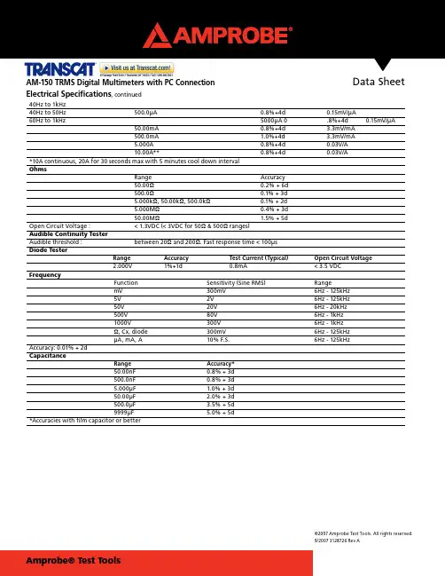
Data Sheet©2007 Amprobe Test Tools. All rights reserved.9/2007 3128726 Rev AAM-150 TRMS Digital Multimeters with PC Connection40Hz to 1kHz40Hz to 50Hz500.0μA 0.8%+4d 0.15mV/μA60Hz to 1kHz 5000μA 0 .8%+4d 0.15mV/μA50.00mA 0.8%+4d 3.3mV/mA500.0mA 1.0%+4d 3.3mV/mA5.000A 0.8%+4d 0.03V/A10.00A** 0.8%+4d 0.03V/A*10A continuous, 20A for 30 seconds max with 5 minutes cool down intervalOhmsRange Accuracy50.00Ω0.2% + 6d500.0Ω0.1% + 3d5.000kΩ, 50.00kΩ, 500.0kΩ0.1% + 2d5.000MΩ0.4% + 3d50.00MΩ 1.5% + 5dOpen Circuit Voltage : < 1.3VDC (< 3VDC for 50Ω & 500Ω ranges)Audible Continuity TesterAudible threshold : between 20Ω and 200Ω. Fast response time < 100μsDiode TesterRange Accuracy Test Current (Typical) Open Circuit Voltage2.000V 1%+1d 0.8mA <3.5 VDCFrequencyFunction Sensitivity (Sine RMS) RangemV 300mV 6Hz - 125kHz5V 2V 6Hz - 125kHz50V 20V 6Hz - 20kHz500V 80V 6Hz - 1kHz1000V 300V 6Hz - 1kHzΩ, Cx, diode 300mV 6Hz - 125kHzμA, mA, A 10% F.S. 6Hz - 125kHzAccuracy: 0.01% + 2dCapacitanceRange Accuracy*50.00nF 0.8% + 3d500.0nF 0.8% + 3d5.000μF 1.0% + 3d50.00μF 2.0% + 3d500.0μF 3.5% + 5d9999μF 5.0% + 5d*Accuracies with film capacitor or betterElectrical Specifications, continuedData Sheet AM-150 TRMSTRMS Digital Multimeters with PC ConnectionProfessional grade and quality performance mark these digital multimeters as a “must have.” Don’t miss the download capability and optional accessories that make these value testers versatile.True RMS (TRMS)■Optical isolated PC interface capability■Auto and manual ranging■Auto power off■Data hold■Peak Hold■Auto & Manual Ranging■■Data Sheet AM-150 TRMS Digital Multimeters with PC ConnectionDisplay:3-4/5 digits 5000 counts LCD displayUpdate Rate:Digital Data 5 per second nominal; 52 Segments Bar-graph 60 per second nominalAC Sensing: True RMSOperating Temperature:0°C to 45°CRelative Humidity:Maximum relative humidity 80% for temperature up to 31°C decreasing linearly to 50% relativehumidity at 45°CStorage Temperature: -20°C to 60°C, 80% R.H. (with battery removed)Pollution degree:2Altitude:Operating below 2000mTemperature Coefficient:nominal 0.15 x (specified accuracy)/ °C @(0°C -- 18°C or 28°C -- 45°C), or otherwise specified Overload Protections:μA & mA: 1A/1kV (or 0.44A/1kV), IR 10kA, F fuseA : 15A/1kV, IR 10kA (or 11A/1kV, IR 20kA), F fuseV, mV, Ω, & Others : 1050Vrms / 1450VpeakSafety:The meter (all versions) is protected, against the users, by double insulation per EN61010-1 andIEC61010-1 2nd Edition (2001) to CAT III 1000V & CAT IV 600V. The meter (all versions) also meetCSA C22.2 No. 1010-1-92* to CAT III 1000V.Terminals (to COM) ratings:V / A / mAμA: Category III 1000 Volts AC & DC, and Category IV 600 Volts AC & DC.E.M.C.:Meets EN61326In an RF field of 3V/m:Capacitance function is not specified. Other function ranges: Total Accuracy = Specified Accuracy + 30 digits.Performance above 3V/m is not specifiedPower Supply:Single standard 9V battery NEDA1604, JIS006P or IEC6F22 for AM-120 & AM-130, and singlestandard 9V alkaline battery NEDA1604A, JIS6AM6 or IEC6LF22 for AM-150Power Consumption: 2.6 mA typicalLow Battery:Below approx. 7VAPO Timing:Idle for 17 minutesDimension:L193mm X W97mm X H46mmWeight:370 gmGeneral SpecificationsData Sheet AM-150 TRMS Digital Multimeters with PC ConnectionElectrical SpecificationsAccuracy is +/-(% reading digits + number of least significant digits) or otherwise specified, at 23°C +/- 5°C & less than 75% R.H.DC VoltageRange Accuracy50.00 mV 0.12% + 2d500.0 mV 0.06% + 2d5.000V, 50.00V, 500.0V, 1000V 0.08% + 2dNMRR : >60dB @ 50/60HzCMRR : >120dB @ DC, 50/60Hz, Rs=1kΩInput Impedance : 10MΩ, 16pF nominal (44pF nominal for 50mV & 500mV ranges)AC VoltageRange Accuracy50Hz to 60Hz50.00mV, 500.0mV, 5.000V,50.00V, 500.0V, 1000V 0.5% + 3d40Hz to 500Hz40Hz to 50Hz 50.00mV, 500.0mV 0.8% + 3d60Hz to 500Hz 5.000V, 50.00V, 500.0V 1.0% + 4d1000V 1.2% + 4d500Hz to 20kHz50.00mV, 500.0mV 0.5dB*5.000V, 50.00V, 500.0V 3dB*1000V Unspecified*Specified from 30% to 100% of rangeCMRR : >60dB @ DC to 60Hz, Rs=1kΩInput Impedance : 10MΩ, 16pF nominal (44pF nominal for 50mV & 500mV ranges)TemperatureRange Accuracy*-50℃ to 1000 ℃0.3% + 3d-58℉ to 1832 ℉0.3% + 5d*Thermocouple range & accuracy not includedDC CurrentRange Accuracy Burden Voltage500.0μA 0.2%+4d 0.15mV/μA5000μA 0.2%+4d 0.15mV/μA50.00mA 0.2%+4d 3.3mV/mA500.0mA 0.2%+4d 3.3mV/mA5.000A 0.2%+4d 0.03V/A10.00A** 0.2%+4d 0.03V/A**10A continuous, 20A for 30 seconds max with 5 minutes cool down intervalAC CurrentRange Accuracy Burden Voltage50Hz -- 60Hz500.0μA 0.6%+3d 0.15mV/μA5000μA 0.6%+3d 0.15mV/μA50.00mA 0.6%+3d 3.3mV/mA500.0mA 1.0%+3d 3.3mV/mA5.000A 0.6%+3d 0.03V/A10.00A** 0.6%+3d 0.03V/A。

CONTENTSIntroduction P age 4 - 5 Bene ts / ApplicationsPage 6 - 7The system P age 8 - 13Experience Smart MONITORP age 14 - 15EU R O P E ‘S L E A D E R I N S I G N AL L I N GSmart MONITOR is the smart MDC alternative for industrial companies looking for a way to quickly and easily gather reliable data to optimise their manufacturing processes. Smart MONITOR provides all of the relevant data for machines, systems and manual workstations easily at the touch of a button. Unlike conventional,complex MDC systems, Smart MONITOR is a simple, wireless-based retrofit solution for signalling and analysing your entire production facility - at a glance.Christian Höhler, Research & Development DirectorEVERYTHING UNDER CONTROL WITH Smart MONITORWith signal devices, the control station module or a messageon your smartphone you can shorten your response times and optimiseyour manufacturing process, with the guarantee that you will nevermiss a critical situation.Everything is documented and the reports also show you how topermanently improve your processes and productivity.Smart MONITORWith Smart MONITOR we help to make processes faster, leaner, better and more efficient - simply at the push of a button. The simple, wireless-based retrofit solution for signalling and analysing your entire production area ensures further growth and that you are always a step ahead of your competitors.THE SYSTEMSmart MONITOR from WERMA consists of a wireless transmitter, a wireless receiver and the software. The robust and proven wireless network for the production environment intelligently searches for the best connection and thereby ensures the simplest integration into your production process. The included software already has integrated analysis and reporting tools.TRANSMITTERWIRELESS DATA MONITORING• Can be integrated into the signal tower as an additional element • M onitors the status and counts the output of up to 50 machines or workstations• Data transferred wirelessly to the receiver • Initiates processes, starts and stops machinesRECEIVERSECURE DATA COLLECTION• R eceives all the data sent by the transmitters in the network• T ransfers and saves the data to a Microsoft SQL databaseSOFTWARECENTRAL CONTROL STATION• C ontrol station offers an overview of all machines, equipment and workstations • Retrospective analysis of data • Process optimisation• React quickly to production disruptions • Produce reportsINTUITIVE AND CLEAR –THE WIN SOFTWAREThe software supplied with the system is easy to install and leads the userthrough a series of steps to establish an individual network. It displays thestatus condition of signal lights installed in the system, enables the user toanalyse runtimes, identify causes of disruption in operations and thereforeimprove efficiency.KEEP UP TO DATE WITH CHANGESMESSAGING SERVICEReact quickly regardless of your current location. If the status of a machine or workstationchanges an Email can be automatically sent to a PC or Smartphone of the personresponsible. You can select to whom and after which time interval of the statuschange the Email is to be sent.OBTAIN TRANSPARENCYRUNTIME MODULEThe Runtime Module enables you to check the operation and down-times of your machines or workstations. This allows you to compareDOCUMENT PROBLEMSERROR ANALYSISeliminated.SIMPLY CLEVER REFERENCESA large number of customers already rely on WERMA technology - and thereby make their production safer, better and more e cient. You can nd references and customer applications at:HOTLINE:Smart MONITORP hone + 49 74 24 95 57- 153Fax+ 49 74 24 95 57- 44**********************EXPERIENCEYOUR POSSIBILITIES FOR YOURSELFLive demonstration. Lean Factory.Visit one of our numerous roadshows throughout Germany. Register at:EXPERIMENT WITH THE PRODUCT INFind out more by ordering our test box – without any obligation - at:***********************This offer may not be available in all markets/smartmonitorYOUR FACILITY TEST BOX*WERMA Signaltechnik GmbH + Co. KG Dürbheimer Str. 15D - 78604 Rietheim - W eilheim Phone + 49 74 24 95 57- 0Fax + 49 74 24 95 57- 44**************WERMA Signaltechnik Niederlassung Neuhausen am Rhf. Rheingoldstrasse 508212 Neuhausen am Rheinfall SwitzerlandPhone + 41 52 674 00 60Fax + 41 52 674 00 66www.werma.ch*************WERMA SARL56, Rue Colière69780 MionsFrancePhone + 33 4 72 22 37 37Fax + 33 4 72 22 37 64www.werma.fr*************WERMA BENELUX Poortakkerstraat 41C9051 Sint-Denijs-WestremBelgiumPhone + 32 9 220 31 11********************* WERMA (UK) Ltd.11 Regent Park37 Booth DrivePark Farm Industrial Estate Wellingborough NN8 6GRGreat BritainPhone + 44 15 36 48 69 30Fax + 44 15 36 51 48 10****************.ukWERMA USA Inc.6731 Collamer RoadEast Syracuse, NY 13057 USA Phone + 1 315 414 0200Fax + 1 315 414 0201*****************WERMA (Shanghai) Co., Ltd.No. 8, High Technology Zone, No. 503, Meinengda Road, Songjiang, Shanghai, P. R. C201613 ChinaPhone + 86 21 57 74 - 00 22Fax + 86 21 57 74 - 66 01**************.cnPart Numbers Smart MONITORWIN slaveOrder no. 860 640 02WIN transmitterOrder no. 860 640 05WIN slave performanceOrder no. 860 640 12WIN transmitter performanceOrder no. 860 640 15WIN slave controlOrder no. 860 640 22WIN transmitter controlOrder no. 860 640 25WIN ethernet master Order no. 860 000 06WIN ethernet receiver Order no. 860 000 07COUNTING MODULEThis hardware monitors up to six different statuses and counts a quantity pulse. This information is transmitted to the receiver.CONTROLLING A SIGNAL TOWERIn combination with the software, this hardware allows the actuation of a signal tower or an external application (start machine, stop machine etc.).STATUS MONITORINGThis hardware monitors up to eight different statuses and transmits them to the receiver.1. WIRELESS NETWORKINGT R A N S M I T T E RR E C E I V E RTerminal elementOrder no. 640 800 00Terminal element + Base with integrated tubeOrder no. 640 810 00 +975 840 10Terminal element + Bracket for base mounting Order no.640 800 00 + 960 000 02BuzzerOrder no. 645 800 752 tone sirenOrder no. 645 870 75LED Permanent light red Order no. 644 100 75LED Permanent light green Order no. 644 200 75LED Permanent light yellow Order no. 644 300 75LED Permanent light clear Order no. 644 400 75LED Permanent light blue Order no. 644 500 75Twin LIGHT redOrder no. 647 110 75Twin LIGHT yellowOrder no. 647 310 75Twin LIGHT greenOrder no. 647 210 75Twin LIGHT clearOrder no. 647 430 75Twin LIGHT blueOrder no. 647 510 75LED Permanent lightOrder no. 649 240 02LED Permanent lightOrder no. 649 240 04Twin LIGHT Order no. 649 000 01LED Permanent lightOrder no. 649 240 05LED Permanent lightOrder no. 649 240 06Twin LIGHT Order no. 649 000 022. SIGNAL TOWERPRE-ASSEMBLED SIGNAL TOWER SIGNAL ELEMENTS (UP TO A MAXIMUM OF 4)Base mounting Base mountingTube mounting Tube mountingBracket mounting06/17 ∙ 990.223.02 ∙ E。

1QRO Fixed site ANPR - 2 laneRe-deployable zoomable High Definition intelligent ANPR camera The Rapier 50IQ is a new "cost effective" i ntelligent High Definition ANPR camera incorporating full data delivery utilising UTMC version 1.2, to the QRO Check-IT Second Generation Server product.With the increase in demand for intelligent High Definition ANPR cameras arriving in themarketplace, functionality and price are becoming key differentiators between the multitudeof current offerings. QRO are working in partnership with MAV to deliver a complete end to end roadside ANPR system , utilising a cost-effective function rich High Definition intelligent ANPR camera at the client end and the latest UTMC Version 1.2 data protocol to deliver the ANPR results to the QRO Check-IT Second Generation Server.The Rapier 50IQ is built upon the already successful camera and illuminatorcombination from the Rapier 50, which is capable of reading number plates up to50m away and providing night-time visible make and model monochrome imagesfrom the overview camera at distances up to 25m. Both the IR and colour channelsare 1280(H) x 720(V) sensors, fitted with motorised zoom lenses, providing an 8mField of View and capable of 2 lane ANPR.Access to the camera for setup and commissioning purposes is via a standard web browser i nterface with password protection available for the Administrator functions such as data format, ANPR engine type and network configuration. An external 4G/3G/WiFi/GPS d ual SIM modem router is housed in a small environmental enclosure along with the cameras p ower o ver e thernet (POE) power supply. This would allow for cameras within the vicinity to employ a single modem for data transmission by utilising a WiFi connection to a single router modem negating the need for a SIM per camera.Key Points❖2 lane 8m f ield of v iew ❖Visible night time overview image capture ❖Intelligent o verview image cropping in order to meet NASP file size requirements ❖UTMC 1.2 data protocol ❖Fully tested data integration with QRO’s Check-IT Second Generation Server (CSGS)❖14 Watts p ower consumption lending itself to Wind and solar powered options ❖Simultaneous HD v ideo recording/ANPR capabilityTo request a demonstration please contactJames Bristow: 01604781890,*****************************.ukNight time overviewQRO Fixed site ANPR - 3 lane Re-deployable zoomable High Definition intelligent ANPR camera3 lane (12m) coverageAll-in-One Intelligent Camera Full HDimage with truEZoom™ Dual ANPRwith Overview maxIRange™Illumination Why buy Rapier IQ:350?MULTI LANE – High resolution 1080p images providing excellent recognitionINTEGRATED ANPR ENGINE – Provides high accuracy reads with meta data JSON WEB SERVICES – Simple integration into applications using open interfaceZOOM CAMERAS – Fully controllable truEZoom™ for the perfect field of view POWERFUL PULSED IR – maxIRange™ for true day/night number plate recognition ECO POWER / PoE+ - Low power consumption, optionally powered from 802.3 at PoE+ FoV – Provides up to 12m / 3 lane coverage from a single camera API CONTROL - Full control and live feedback of ANPR, camera and IR settingsIntelligence to capture 3 lanesIncorporating dual 1080p HD images, motorised zoom, high speed ANPR recognition and maxIRange™ pulsed IR lighting in one small but highly efficient unit, the IQ:350 camera offers fixed-site options for users of all-in-one intelligent ANPR cameras.The IQ:350 provides recognition for up to 12m lane width for detection of plates and is simple to set up with truEZoom™ for perfect field of view at distances from 10m up to 40m. Set -up is performed using the camera’s API or from any browser using the IQ’s web set -up with live video feed.The high definition global shutter ANPR camera module is synchronized to upgraded infrared (IR) pulsed LEDs to offer superior license plate recognition to match the increased capture width that 1080p resolution offers.The IQ:350 performs its ANPR recognition within the camera using a custom embedded processor. Real time recognition is performed on raw 1080p HD images.The IQ:350 offers store and forward buffering to provide up to one million cached reads or immediate data transfer via an API supporting JSON, FTP, UTMC1.2 and w eb s ervices. The IQ:350 is hermetically sealed to IP68 and can be powered using PoE+ or 10-15V DC to give a single cable install suitable for vehicles or fixed sites where the smaller physical size is appealing.2C amera SpecificationsRAPIER IQ:350 Recognition RangeCapture of up to 12m of traffic lanes from 10m to 40m based on 850nm IR on EU retro-reflective plates SensorANPR: 1/3” 1920(H) x 1080(V) 16:9 global shutter, 25 fps Overview: 1/3” 1920(H) x 1080(V) 16:9 rolling shutter (global optional), 25 fps Motorised LensANPR: motorized zoom (4-12mm or 8-22mm), focus and p-iris control Overview: motorized zoom (4-12mm or 8-22mm), focus and auto DC iris (p-iris optional) IR illumination4 pulsed LED arrays with lenses (850nm standard. White light, 740nm or 940nm optional) Optical FiltersIR: Bandpass matched to LEDs OV: Day/Night IR Cut Filter (auto/manual) Camera Control Integrated web server provides full camera and illuminator setup pages and live preview from any connected browser (no plug-ins required)ANPR Engine FunctionalityANPR ProcessorDual Core DSP with co-processor and two channel internal parallel video input ANPR Software /PresetsANPR license and configuration upload via web based configuration pages for simple remote management ANPR EngineProtocolJSON web services provide full access to overview and plate patch images and metadata as push or pull messages for easy integration into applications (O/S independent) and via web pages ANPR MetadataMultiple plate tracking with IDs, full availability of plate movement/size data through field of view ANPR StorageOnboard storage 8GB (optionally 32GB) for up to 1 million buffered reads ANPR Features Image cropping options for Overview image, advanced de-skew and yaw correction, character spacing validation, country of origin matching, lane determination, direction of travel, plate tracking and geometryPhysical SpecificationsOperating VoltagePoE+ (803.2at type 2) or 10-15VDC suitable for battery power Network Connections10/100 Base-T physical Power ConsumptionNominally 14W Dimensions163 x 163 x 145mm (cylindrical) excluding connectors, mount and sunshield Weight2.5kg excluding mount and sunshield EnclosureIP68 hermetically sealed. Hard anodized aluminum with mount options Temperature/Humidity -30°C to 55°C operating with relative humidity 0%RH to 100%RH (hermetically sealed)ServiceCustomer ServiceFriendly, helpful service for product ordering and repair returns Technical SupportComprehensive pre and post-sale technical support for full life of the product Warranty12 month warranty, extended warranties and factory repair/replacement programmes available Long Term SupplyComplete support for the life of the product Training Comprehensive product training programmes for customers RAPIER IQ:350 SPECIFICATIONThe Rapier IQ:350 is available in two models for short range 4-12mm zoom, or mid-range 8-22mm zoom.。

中文版目录1安规 (3)1.1重要信息 (3)1.2安全符号 (3)1.3一般警告 (3)2仪器说明 (4)2.1仪器说明 (4)2.2液晶显示器 (4)2.3键盘 (6)2.4接口 (6)3安装 (6)3.1装箱清单 (6)3.2安装 (8)4开始操作 (9)4.1启动 (9)5主要功能 (10)5.1高度及直径/中心线测量的选择 (10)5.2高度测量 (11)5.3直径及中心线的测量 (11)6辅助功能 (13)6.1参考平面 (13)6.1.1参考平面的选择 (13)6.1.2参考预设值的赋值 (13)6.2精度的选择 (13)6.3测头常数的设置/保存 (14)6.4测量单位的选择 (14)6.5在最大/最小/差值模式下测量 (14)6.5.1在最大或最小值下测量 (15)6.5.2在差值模式下测量 (15)6.6显示器置零 (16)7数据传输及输出 (17)7.1RS232 (17)7.2数据传输配置 (17)7.3脚踏开关 (18)8操作及调整 (18)8.1气浮 (18)8.2显示模式 (18)8.3重置 (19)8.4测量力的调整 (19)8.5浮动测头悬架的调节 (20)8.6探测运动 (20)8.7电池组(寿命、功率...).. (21)8.8更换电池 (21)8.9擦拭 (22)9售后服务 (22)9.1客诉/维修 (22)9.2代理商 (22)10技术规格 (23)1安规1.1重要信息为免于由于的错误的操作而引起损坏,请仔细阅读下列的指导书。
由于不按本手册进行不适当的操作而引起的损坏,TRIMOS公司不承担任何责任。
1.2安全符号本手册中会用到下列安全符号:1.3一般警告一般警告,操作建议有遭电击的危险静电保护防静电干扰:静电能使仪器的电子元件受到损坏。
为防止此类的损坏,勿与连接器的PIN有任何接触。
为防止破坏仪器的性能和发生意外,请勿对仪器进行拆除。
如果由于某种原因,必须打开电子单元,只有授权人员才能进行此操作。

内容协作平台Array TRS WCM模板编辑器选件用户手册V 7.0北京拓尔思信息技术股份有限公司Beijing TRS Information Technology Co., Ltd.版权说明本手册由北京拓尔思信息技术有限公司(以下简称TRS公司)出版,版权属TRS公司所有。
未经出版者正式书面许可,不得以任何方式复制本文档的部分或全部内容。
©北京拓尔思信息技术有限公司版权所有。
保留所有权利。
是北京拓尔思信息技术有限公司的注册商标。
关于本手册TRS WCM 模板编辑器选件(以下简称模板编辑器)是TRS公司发布的内容协作平台TRS WCM 的一套扩展功能软件,可以作为Macromedia Dreamweave(这里的Dreamweaver特定为7.0及其以上版本)的功能插件,利用可视化的编辑环境,辅以快捷的置标使用向导,同时使用WebServices技术保证以Dreamweaver为载体的客户端,可以和提供模板下载的TRS WCM 服务器端同步工作,使得TRS WCM 模板开发人员可以方便地进行模板的编辑和维护。
本手册详细地介绍了有关模板编辑器的使用方法和技巧,是用户熟悉掌握模板编辑器不可或缺的参考资料读者对象本手册的使用对象是TRS WCM 产品的模板编辑和制作人员。
使用者应至少具备以下知识:●熟悉Dreamweaver 的使用;●熟悉TRS WCM 产品的使用;具备一定的TRS WCM 模板制作的能力;手册组织本手册的内容组织如下∶●第1章安装说明介绍模板编辑器安装、卸载和启动。
●第2章基本流程简单地介绍模板编辑器的使用流程,即:使用这样一个工具大概能做什么事情。
●第3章详细使用说明详细介绍Dreamweaver中模板编辑器客户端的使用方式、利用这个工具工作的流程,是本文档的核心部分。
●第四章FAQ用户反馈TRS公司感谢您使用TRS 产品。
如果您发现本手册中有错误或者产品运行不正确,或者您对本手册有任何意见和建议,请及时与TRS公司联系。
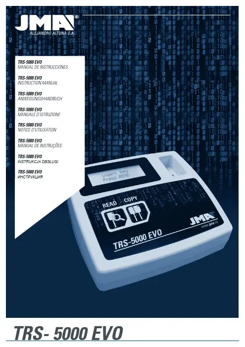
TRS-5000 EVOManual de instruccionesTRS-5000 EVOinstruction ManualTRS-5000 EVOanweisungshandbuchTRS-5000 EVOManuale d’istruzioneTRS-5000 EVOnotice d’utilisationTRS-5000 EVOManual de instruçõesTRS-5000 EVOINSTRUKCJA OBSŁUGITRS-5000 EVOИнструкцИяTRS- 5000 EVOKeY cutting Machine TRS-5000 EVO instruction Manual1.- PRESEnTaTiOn and gEnERal aSPEcTS1.1 general aspects1.2 transport and pacKaging2.- TEchnical SPEcificaTiOnS2.1 the Machine’s suppleMentarY eleMents2.2 the Machine’s Main eleMents3.- STaRTing ThE machinE3.1 situating the appliance3.2 installing and fitting the equipMent4.- c OPying kEyS4.1 local Mode with no pc connection.4.1.1 inforMation visible on the displaY in local connection Mode4.1.2 inforMation supplied when copYing a texas crYpto4.1.3 inforMation supplied when copYing a philips crYpto ii.4.2 error Message codes• Instructions manual.• TPX4 support (two units).2.2 ThE machinE’S main ElEmEnTS• Two push buttons (READ and COPY).• One on/off switch.• One female DB9 connector for future RS 232 series line connections.• Two USB connectors (CL for CLoner and TR for TRS5000 EVO).• One DC power supply connector.• One 4x20 character alphanumeric display.3. STaRTing ThE machinE3.1 SiTuaTing ThE aPPliancEOnce the machine has been carefully unpacked, it must be placed on a surface that is not made of metal or any other material that may generate electromagnetic interference when reading, given that the antenna is the most sensitive area to interferences and therefore to the metal components that distort the signal captured from the key as well as the tuning frequency. As an example:A correct location for situating the machine may be a wooden desk.It must also be taken into account that the machine must be situated at a distance of at least between 80 and 100 cm from any electromagnetic interference source (operator screens, televisions, electrical communication elements, motors, walky-talkies, mobile phones, etc.).3.2 Installing and fitting the equipmentOne positioned correctly, all the material received with the appliance can be installed.To do this, proceed as follows:1. Check that the material in the box received from the manufacturer is in accordance with point2.1 of this manual in reference to the elements the machine includes.2. Check there is a 110/220V power socket available in the premises and that the power supply received is correct: 100-240 Vac / 50-60Hz and 9V /2A. Connect the power supply to the TRS-EVO.The inclusion of the (4x20) alphanumeric display on the TRS-EVO enables reading of all the transponders to be optimised, thus offering detailed and complete information about them.Following, and to summarise, the attached table shows the messages that appear when reading an original key as well as the transponder to be inserted for cloning the key.1. PRESEnTaTiOn and gEnERal aSPEcTS1.1 gEnERal aSPEcTSFollowing the evolution of the TRS family, the launch of the new TRS5000 EVO is presented.As such, and taking the renowned and successful TRS5000 as a base, a more robust and compact machine has been developed that clones most of the encrypted and fixed, automatic and PC mode transponder families available on the market:•Megamos fixed code •Temic fixed code •Nova fixed code•Philips fixed and encrypted code •Texas fixed and encrypted codeThis evolution is true to the philosophy for the entire TRS range, which can be translated as “the simpler the better for the user”.In line with this maxim, the TRS EVO still has the usual READ/COPY buttons present in the entire range.In this new evolution, JMA has worked considerably on the te-chnical simplification of the solution provided as a whole (TRS5000+TPXCloner+TPHCloner).In fact, substantial effort has been made to compact all the external hardware and cabling used previously (TPX Cloner + TPH Cloner) whose functionality is supplied with the codes that bear the original keys from the Texas and Philips Crypto families respectively, in one unit.1.2 TRanSPORT and PackagingThe machine is supplied protected by polystyrene packing and inside a cardboard box with the following dimensions and weight:• Width = 275 mm.• Length = 320 mm.• Height = 170 mm.• Weight = 550 g.When unpacking the machine, check carefully to see if it has been damaged during transportation. If you find any problems, please contact Altuna JMA Group’s technical or customer service department and do not use the machine.2.TEchnical SPEcificaTiOnSThe TRS–5000 EVO duplicating machine, in addition to offering the same and the complete reading and cloning range of the main transponder manufacturers, offers complete information on the detail of these readings.Also, with the compacting of the product (integration of the two external cloners (TPX+TPH), on a single plate) the errors have been suppressed that are often generated by the client when connecting between the different devices (TRS TPH TPX).The machine is updated using the upper USB port (known as the TR).The other USB port (known as the CL), is enabled for updating the new compact Cloner (TPX+TPH), so that new vehicle models can be easily added for later cloning.2.1 ThE machinE’S SuPPlEmEnTaRy ElEmEnTSAfter unpacking the TRS-5000 EVO duplicating machine, the following components should be found:• Power supply 100-240 Vac / 50-60 Hz and 9V / 2.5 A.• USB cable type A-B (1.5 m long), for interconnection between the PC andthe TRS 5000-EVO.4 .cOPying kEySThe steps to be followed in order to make a copy are:4.1 lOcal mOdE wiTh nO Pc cOnnEcTiOn•After entering the customer’s original key in the antenna housing, press the read button. A message will appear advising the transponder’s JMA type-reference that contains the original key read, as well as the transponder on which JMA advises the duplicate.Covers all fixed and most encrypted transponders (Texas/Philips). If the transponders were encrypted from other brands such as Megamos or Temic, the device will show the transponder’s identification with its JMA reference and will advise how to proceed to activate the key, generally redirecting to the transponder’s manual and the use of a programming machine (TRACK7).•Next, and following the step-by-step indications on the display, the key is removed and the new key entered on which the copy will be made together with its corresponding transponder.When making the copy, it is advisable to enter the key in a non-mechanical manner, since due to the shavings or burrs that may remain on the key that may interfere with the equipment’s electronics if they fall through the antenna or because the copy may be defective, it is preferable to cut the key after successfully completing this section.•Once the copy has been made, the device itself will indicate whether the key is correct or erroneous.In the case that more than one copy of the same key is required, repeat all the steps in the previous paragraphs, keeping in mind that it is advisable to use the original key provided by the customer as the base and the exact transponder with the reference recommended by JMA as the “copy base”.The only exception is for the Philips Crypto, for which as many copies as desired can be made without having to go through the entire process again.4.1.1 infORmaTiOn ViSiblE On ThE diSPlay in lOcal cOnnEcTiOn mOdEWhen cloning the encrypted transponders, Texas as well as Philips, there is no need for a connection to the PC or to the external cloning device coupling (TPX Cloner + TPH Cloner), given that in the TRS EVO’s new and compact design, all functionalities have been included in one unit.During initialisation, the following messages will be shown on the display:JMA TRS-5000 EVO S/N: 0123456789ABCDEFFWR: xxClR: TPx ClONER FOuNDThe three first rows show the name, serial number and firmware version of the TRS 5000 EVO.The last row shows, successively and alternately, the messages that indicate whether or not the Texas and Philips encrypted transponder copy functions are enabled.The message “TPX Cloner Found” indicates that the TRS EVO is operational for cloning the Texas Crypto.Next, the “TPH Cloner Found” message will appear, which indicates that the TRS EVO is also operational for cloning the Philips Crypto.TPH ClONER FOuND TPH VER.: 39.1.6Finally, after the message “TPH Cloner found”, the firmware version will be displayed that controls the cloning of the Philips Crypto and which can be easilyupdated using the CL USB port.if you have any problems or questions, please contact technical support: mailto:**********If the key entered has a first generation Texas Crypto transponder that is not recognised by the TRS EVO and thus does not appear in the above table, thedisplay will show the following message:The TPX1 and TPX4 can be programmed as many times as desired. This is not the case with the TPX2. because it is an OTP (one time programmable) transponder, it can only be recorded once, after which it will be disabled for future copies on the same transponder.Similarly: if the key entered does not have a transponder, the display will show the following advice message:NO CHIPNO TRANSPONDERit must be mentioned that some high range cars,bmw, mERcEdES use a rolling code system (evolutionarilyencrypted), from the appearance of the first vehicles from around 1995, and although the machine shows that the copy is possible, this cloning will not be valid because the codes constantly evolve following an unknown protocol. avoid duplicating thekeys for vehicles with manufacturing dates after 1995.4.1.2 inforMation supplied when copYing a texas crYptoNext, the process will be shown for cloning a Texas Crypto transponder thatis mounted for example on a Ford Focus (2007) and the messages shown onthe TRS EVO display:Once the original key is analysed, the following detailed information will beshown:• JMA code for the chip that holds the key (TP 20).• Transponder type and manufacturer (Texas Crypto).• Manufacturer of the vehicle that uses it (FORD).• The JMA transponder that must be used for cloning this key (TPX2).• Information about the transponder’s internal structure, which will bedifferent depending on the chip manufacturer. As an example, a FORD keywould be (Password: 03, Manufacturer’s code: 01, Serial number: 00 andUser serial number: 2FAC03, bits locked, which refers to the write-protectedinformation pages, 0010 (Pag3 LOCK) and finally if the old DST40 algorithmor the new DST80 is used).After entering the JMA (TPX2) transponder on which the cloning on the ante-nna will be carried out, press the COPY button.The TRS EVO will begin to analyse the transponder from the original keyentered.Once discovered, this information will be written on the TPX2 and it willbeep once if the copy is executed correctly.4.1.3 inforMation supplied when copYing a philips crYpto ii.To finalise, it shows the cloning process of a second generation PhillipsCrypto transponder, HT2, used by a Citroen C3 and the messages that woulddisplay TRS EVO.Once the original key is analysed, the following information will be shown:• JMA code for the chip that holds the key (TP 12).• Chip model included (PCF7941).• Transponder type and manufacturer (PHC – Philips Crypto).• The JMA transponder that must be used for cloning this key (TPX4).•Information about the transponder’s internal structure, which will bedifferent depending on the chip manufacturer. As an example, a CITROENkey would be (Serial number: B9B66969, if it is write-protected (LOCK) andthe type of coding used (Manchester)).To activate the TPH Cloner mode supported by Philips Crypto, the processcommences by pressing the COPY key on the original key.While the HT2 algorithm used by Philips Crypto second generation is beingloaded into the memory, the TRS EVO will display the following message:When the FPGA has loaded the corresponding memory, the following will beshown on the display:And the TRS EVO will be ready for analysing and completing the followingsteps, requesting a return to read the original key:Next, the transponder’s type and brand will be indicated, as well as whetherit is an original transponder or a copy (Philips crypto type):A Virgin TPX4 must then be entered to configure it in capture mode (Sniff)and to be able to capture the data, verifying that the copy has been madecorrectly.If the TPX4 has been used before, the TRS will detect that and you can use itagain, as many times as you want, by deleting it.A message will appear on screen indicating that the first step has beencompleted successfully.The TRS EVO will wait until the data stored in a TPX4 are introduced (these data contain the information flows that are transmitted between the ECU and the original key).This data will be stored in the TRS EVO’s RAM memory so that it is available during the search process.With successful conclusion in this case, the data preparation process conside-red in (Step 2) prior to the actual search is:Next, and using the information provided from the sniff, attempt to access the transponder’s internal information pages:The search process duration is totally variable and depends on from where the data is stored in the 24GB’s from available information:Once access is available to the transponder records map, the data is copied either from the same transponder during the sniff process or from another TPX4, indicating whether or not the copy has been made successfully.iThe Philips Crypto II family provides the possibility to clone as manytransponders as required by pressing COPY once the information in the RAM memory is available in the TRS EVO.4.2 ERROR mESSagE cOdESThe error and warning messages shown on the display are listed based on the status of the process you are in.If the list of quick solutions given below does not solve the related problem, a detailed study of the communication between the immobiliser ECU and the transponder will be necessary.The error / warning list and the possible solutions are shown below:After display number 14 and with TPH_BLANK (TPX4 in data capture modeAfter the same Display DispX, (but after reading data from key in encryptedAll the error and warning codes that may appear during the cloning processJma headquarters alEJandRO alTuna, S.a.Tel +34 943 79 30 00Fax +34 943 79 72 43 Bidekurtzeta, 6P.O.Box - Apdo. 7020500 Arrasate - Mondragón Gipuzkoa – SPAINwww.jma.es*************Jma aRgEnTinaJMA ARGENTINA S.A.Tel +54 336 4 462 422Fax +54 336 4 462 422Av. Central Acero Argentino Oeste 678 Parque industrial COMIRSA2900 San Nicolas (Prov. Buenos Aires) **********************Jma fRancETel +33 01 39 22 42 10Fax +33 01 39 22 42 11 Technoparc13, rue Edouard JeanneretF- 78306 Poissy Cedexwww.jma france.fr*******************************Jma indiaJMA KEYS INDIA PVT. LTDTel +91 124 428 5450Fax +91 124 428 5451H-239 & H-240, Sushant Shopping Arcade Sushant Lok-1, Block B122002 GurgaonHaryanawww.jma keys.in***************Jma maROcJMA MAROC S.A.R.L.Tel +212 656 195 195Fax +212 520 150 536El OulfaCasablancaMarruecoswww.jma.ma**********Jma mEXicOLLAVES ALTUNA DE MEXICO S.A de C.V Tel +52 33 3777 1600Fax +52 33 3777 1609Av. Aviación No. 5520Col. San Juan de OcotánC.P. 45019 Zapopan, Jalisco.mx**************.mx Jma PERÚJMA Perú S.A.C.<<Tel +51 639 9300Av. Los Paracas 130, UrbanizaciónSalamanca,Distrito Ate, Lima*****************Jma POlSkaJMA POLSKA Sp. z.o.o.Tel +48 42 635 12 80Fax +48 42 635 12 8591- 342 Łódź, ul. Zbąszyńska 3www.jma polska.pl******************Jma PORTugalaltuna portugalCOMERCIO DE CHAVES UNIPESSOAL, LDA.Tel +351 219 947 470Fax +351 219 947 471Urbanizaçâo dos Areeiros, Lote 67 C/v2695-733 Sâo Joao da Talhawww.jma *************************Jma uksKs ltdTel +44 144 229 1400Fax +44 144 286 3683Unit 2, CanalsideNorthbridge RoadBerkhamstedHerts HP4 1EG****************.ukJma uRuguayJMA URGUAY S.A.Tel +598 2908 1175Fax +598 2900 6681Mercedes 142011100 MontevideoUruguay.uy************.uyJma uSaaltuna group usa inc.Tel +1 817 385 0515Fax +1 817 385 48501513 Greenview Drive75050 Grand Prairie, Texaswww.jma ***************Member Of altuna groupwww.jma.es。

软件产品说明(Software Product Description)产品名称(中文)TRS媒资管理系统产品名称(英文)TRS Media Asset System (简称TRS MAS)版本Version 5.0发布时间2012年8月目录互联网时代的媒资管理 (2)TRS MAS:产品概述和定位 (2)版本划分 (3)主要特色 (4)产品功能 (4)视频采集和加工 (4)视频管理和审核 (5)视频发布和推送分发 (5)视频检索 (6)视频点播 (6)视频直播 (6)用户和权限管理 (6)系统管理 (7)性能指标 (7)运行环境、部署结构和建议 (8)附录1:相关产品 (10)附录2:概念术语 (10)互联网时代的媒资管理媒资管理系统起源于电视台,其最初的作用是解决电视台视音频资料(形式主要是磁带)的存储和管理利用,和其他行业机构本没有关系。
但随着信息技术的发展,尤其是Web 2.0/3.0的到来、宽带网络、移动互联网的逐渐普及,越来越多的行业机构有了自己的音视频资源,并且积累地越来越多,在实际使用过程中出现了各种问题,比如:●音视频资源存放分散无序(光盘中、PC中、服务器中、U盘中...),导致查找和获取效率很低;●有些资源的内容其实是完全相同的,浪费了不少空间和重复比较的精力;●资源利用困难:音视频文件格式繁多,很难通过互联网高效地共享给异地的同事、客户或合作伙伴;需要花费大量时间和精力对不同格式的音视频进行转码,以支持互联网和智能终端;●在互联网上发布和传播音视频,涉及到很多系统和设备,维护管理非常繁杂;出现问题时不易诊断;●音视频资源容易被内部同事误修改或误删除,存在严重的安全隐患;●……在这种背景下,媒资管理逐渐成为了一个跨行业的基础需求。
而针对广电行业的传统媒资管理系统又不能很好地满足普通行业机构的需要,因为他们需要的,不再是以模拟信号、磁带为标志的传统媒资管理;而是以数字化、磁盘为标志的互联网时代的媒资管理。

内容协作平台Array TRS WCM专题制作选件用户手册V 7.0北京拓尔思信息技术股份有限公司Beijing TRS Information Technology Co., Ltd版权说明本手册由北京拓尔思信息技术股份有限公司(以下简称TRS公司)出版,版权属TRS公司所有。
未经出版者正式书面许可,不得以任何方式复制本文档的部分或全部内容。
©北京拓尔思信息技术股份有限公司版权所有。
保留所有权利。
是北京拓尔思信息技术股份有限公司的注册商标。
关于本手册欢迎使用TRS公司的TRS WCM专题制作选件(TRS WCM Special)。
专题制作选件是在TRS WCM V7.0的基础上开发的,不仅继承了TRS WCM的优点,还解决了TRS WCM中模板创建门槛高的问题,利用系统中提供的资源,快速建站,让编辑人员在可视化界面中设计发布的页面,大大降低了技术门槛,提高了建站效率。
本用户手册不但能帮助您快速了解TRS WCM Special从专题创建到发布的工作流程,并通过详细的讲解,让您全面掌握系统所有功能的使用方法和技巧。
手册包括以下各个部分:第1章系统概述第2章开始使用第3章常见任务第4章功能进阶第5章专题的初始化第6章资源智能识别规则第7章常见问题读者对象本手册的读者为TRS WCM Special的使用者。
使用者应具备以下基础知识:●熟悉Windows XP、Windows NT、Windows 2000或Windows 7平台●熟悉Oracle、Microsoft SQL Server、MySql●熟悉Microsoft Internet Explorer的使用●熟悉HTML基本知识和相关的HTML页面制作方法用户反馈TRS公司感谢您使用TRS 产品。
如果您发现本手册中有错误或者产品运行不正确,或者您对本手册有任何意见和建议,请及时与TRS公司联系。
您的意见将是我们做版本修订时的重要依据。
软件标识 (1)许可协议 (2)一、概述 (3)1.1系统简介 (3)1.2系统组成 (3)1.3系统特点 (3)1.4运行环境 (3)二、程序安装卸载与升级 (4)2.1程序的安装与卸载 (4)2.2程序的升级 (4)三、程序使用 (5)3.1设计数据准备 (5)3.2设站定向 (5)3.3启动程序 (5)3.4项目操作 (5)3.4.1打开工程 (5)3.4.2删除工程 (6)3.4.3工程属性 (6)3.4.4工程信息 (7)3.5数据查看 (7)3.5.1水平定线数据 (7)3.5.2垂直定线数据 (8)3.5.3理论断面数据 (9)3.5.4实测断面数据 (10)3.5.5炮孔放样数据 (11)3.6断面测量 (12)3.6.1当前断面测量 (12)3.6.2前后断面测量 (13)3.6.3随机检测 (14)3.7断面放样 (14)3.7.1炮孔文件放样 (15)3.7.2炮孔随机放样 (15)3.7.3线路放样 (16)3.8数据分析 (17)3.8.1超欠挖分析 (17)3.8.2线路坐标正算 (19)3.8.3线路坐标反算 (19)3.8.4断面坐标反算 (20)软件标识软件标识感谢您购买南方隧道断面测量系统软件感谢您购买南方隧道断面测量系统软件,,使用中如有什么问题及修改意见,请与我们联系请与我们联系,,我们将竭诚为您服务我们将竭诚为您服务。
软件标识软件标识在软件CD 标签上标签上,,标有标有该该软件的注册号和版本号软件的注册号和版本号。
请在下面填写上版本号与注册号版本号与注册号,,以便你在需要的时候以便你在需要的时候,,与授权的代理店联系与授权的代理店联系。
注册号注册号::________________________________________版本号版本号::____________________________________许可协议许可协议在使用本产品前在使用本产品前,,请仔细阅读下面的许可协议请仔细阅读下面的许可协议。
393/393 FCCAT III 1500V TRMS Clamp Meter用户手册July 2021 (Simplified Chinese)© 2021 Fluke Corporation. All rights reserved.Specifications are subject to change without notice.All product names are trademarks of their respective companies.有限保证和责任限制在正常使用和维护条件下,Fluke公司保证每一个产品都没有材料缺陷和制造工艺问题。
保证期为从产品发货之日起三(3)年。
部件、产品修理和服务的保证期限为90天。
本项保证仅向授权零售商的原始买方或最终用户提供,并且不适用于保险丝和一次性电池或者任何被Fluke公司认定由于误用、改变、疏忽、意外非正常操作和使用所造成的产品损坏。
Fluke公司保证软件能够在完全符合性能指标的条件下至少操作90天,而且软件是正确地记录在无缺陷的媒体上。
Fluke公司并不保证软件没有错误或无操作中断。
Fluke公司仅授权零售商为最终客户提供新产品或未使用过产品的保证。
但并未授权他们代表Fluke公司提供范围更广或内容不同的保证。
只有通过Fluke授权的销售商购买的产品,或者买方已经按适当的国际价格付款的产品,才能享受Fluke的保证支持。
在一个国家购买的产品被送往另一个国家维修时,Fluke公司保留向买方收取修理/更换零部件的进口费用的权利。
Fluke公司的保证责任是有限的,Fluke公司可以选择是否将依购买价退款、免费维修或更换在保证期内退回到Fluke公司委托服务中心的有缺陷产品。
要求保修服务时,请与就近的Fluke授权服务中心联系,获得退还授权信息;然后将产品连同问题描述寄至该服务中心,并预付邮资和保险费用(目的地离岸价格)。
Fluke对运送途中发生的损坏不承担责任。
mASTRO® APX™O5 Control Head Mobile Radio Quick Reference CardRF Energy Exposure and Product Safety Guide for Mobile Two-Way RadiosATTENTION!This radio is restricted to Occupational use only. Before using the radio, read the RF Energy Exposure and Product Safety Guide for Mobile Two-Way Radios which contains important operating instructions for safe usage and RF energy awareness and control for Compliance with applicable standards and Regulations.Radio Controls Radio On/Off Adjusting Volume Selecting a Zone Selecting a ChannelReceiving and TransmittingSending an Emergency AlarmTo exit emergency at any time, press and hold theEmergency button.Press the Power On/Off button to toggle the power onor off.** The duration that user must press and hold thePower On/Off button to turn off the radio isprogrammable by a qualified radio technician.Turn the Volume Knob clockwise to increase volume orcounterclockwise to decrease the volume.1> or < to ZONE.2> or < button until the desired zone is displayed.3Press H or the PTT button to confirm the selectedzone number.4Press the PTT button to begin transmitting on thedisplayed zone channel.1Press and hold > to scroll to CHAN and press theMenu Select button directly below CHAN. Thedisplay shows the current zone and channel.2Rotate the Mode knob to the desired channel.3Press H or the PTT button to confirm the channel.4Press the PTT button to transmit on the displayedzone channel.1Take the microphone off hook.2Select zone/channel.3Listen for a transmission.ORTurn the Volume Knob.OR> or < to MON then press the Menu Select buttondirectly below MON and listen for activity.4Adjust volume, if necessary.5Press the PTT button to transmit; release to receive.1Press the Emergency button. A tone sounds and thedisplay alternates EMERGENCY and the homedisplay.2 A dispatcher acknowledgment ACK RECEIVEDdisplay follows.AND, Trunking Only:A high-pitched tone indicates that the alarm has beenreceived by the trunked system’s central controller.3Press and hold the emergency button or the PTTbutton to return to normal operation.*PMLN5592G*PMLN5592G MOTOROLA, MOTO, MOTOROLA SOLUTIONS and the Stylized M logo are trademarks or registered trademarks of MotorolaTrademark Holdings, LLC and are used under license. All other trademarks are the property of their respective owners.© 2009–2011, 2013, 2015 by Motorola Solutions, Inc.All Rights Reserved. 06/151303 East Algonquin Road, Schaumburg, Illinois 60196, U.S.A.EnglishSending an Emergency Call (Trunking Only)To exit emergency at any time, press and hold the Emergency button.Sending a Silent Emergency AlarmIf silent emergency alarm is used with emergency call, pressing the PTT button exits the silent mode and initiates the emergency call.Display Status Icons1Press Emergency button.2A tone sounds and the display alternates EMERGENCY and the home display.ORA talk prohibited tone sounds when the selected channel does not support emergency.3Press and hold the PTT button. Speak clearly into the microphone.4Release the PTT to end the transmission.1Press the preprogrammed Emergency button to activate the silent alarm feature.2The display does not change; the LED does not light up, and there is no tone.Receiving a call or data.Transmitting a call or data.The more stripes, the stronger the signal strength for the current site (trunking only).u t VDirect radio-to-radio communication or communication through a repeater.On = Direct Off = RepeaterThis channel is being monitored.Voice muting the affiliated trunking talkgroup or selected conventional channel.On = Enabled Off = DisabledL = Radio is set at Low power.H = Radio is set at High power.Scanning a scan list.Blinking dot = Detects activity on thePriority-One Channel during scan.Steady dot = Detects activity on the Priority-Two Channel during scan.The vote scan feature is enabled.O M KH OR.i j kOn = Secure operation.Off = Clear operation.Blinking = Receiving an encrypted voicecall.On = AES Secure operation.Off = Clear operation.Blinking = Receiving an encrypted voicecall.On = Location feature enabled, and locationsignal available.Off = Location feature disabled.Blinking = Location feature enabled, butlocation signal unavailable.On = User is currently associated with theradio.Off = User is currently not associated withthe radio.Blinking = Device registration or userregistration with the server failed due to an invalid username or pin.Data activity is present.Indicates that the text entry is currently in hexadecimal mode.m l G no{Menu Navigation < or > to Menu Entry.g directly below Menu Entry toselect.H to exit.< or > to scroll through sub-list.g directly below Menu Entry toselect.。
<TRS_TEMPLATE TEMPNAME="嵌套模版名称"></TRS_TEMPLATE>2.导航置标<div class="dh"><ul><TRS_CHANNELS STARTPOS="0" NUM="5" ID="SITE"><li><a href="<TRS_CHANNEL FIELD='_RECURL'/>"><TRS_CHANNEL FIELD="CHNLDESC" AUTOLINK="false" AUTOFORMAT="false">导航条</TRS_CHANNEL></a></li></TRS_CHANNELS></ul></div>3.首页模版简单导航条(首页、各栏目名)<TRS_CHANNELS ID="SITE" NUM="7"><TRS_CHANNEL EXTRA="CLASS='dh_font01'" autolink="true"></TRS_CHANNEL>| (栏目之间的分割线,可以替换或删除)</TRS_CHANNELS>4.复杂导航条—显示下拉子栏目<TRS_CHANNEL id="新闻中心" field="CHNLNAME" autolink="FALSE"></TRS_CHANNEL><li> <TRS_CHANNEL ID="新闻中心" CHILDINDEX=0 AUTOLINK="TRUE"/</li><li> <TRS_CHANNEL ID="新闻中心" CHILDINDEX=1 AUTOLINK="TRUE"/</li><li> <TRS_CHANNEL ID="新闻中心" CHILDINDEX=2 AUTOLINK="TRUE"/</li><li> <TRS_CHANNEL ID="新闻中心" CHILDINDEX=3 AUTOLINK="TRUE"/</li>5.更多置标<TRS_CHANNEL id="某省局动态" field="_RECURL" ></TRS_CHANNEL>6.新闻列表置标<TRS_DOCUMENTS ID="owner"/"新闻中心" NUM="1000" startpos="0" PAGESIZE="20"> 标题:<TRS_DOCUMENT FIELD="DOCTITLE" num="40" AUTOLINK="TRUE">标题</TRS_DOCUMENT>日期:<TRS_DOCUMENT FIELD="CRTIME" DATEFORMA T="yyyy-mm-dd HH:mm:ss">日期</TRS_DOCUMENT></TRS_DOCUMENTS><TRS_DOCUMENTS id="新闻" num="50"><TRS_RECORD NUM=2><TRS_DOCUMENT FIELD="DOCTITLE"/></TRS_RECORD></TRS_DOCUMENTS>8.概览栏目的名称显示(title、导航等)<TRS_CHANNEL id="OWNER" field="CHNLNAME" autolink="FALSE"></TRS_CHANNEL>9.细览详细页置标标题:<TRS_DOCUMENT FIELD="DOCTITLE">标题</TRS_DOCUMENT>日期:<TRS_DOCUMENT FIELD="CRTIME" DATEFORMA T="yyyy-mm-dd HH:mm:ss">创建时间标题</TRS_DOCUMENT>发稿人:<TRS_DOCUMENT FIELD="TRUEUSER">发稿人</TRS_DOCUMENT>来源:<TRS_DOCUMENT FIELD="DOCSOURCE">来源</TRS_DOCUMENT>正文:<TRS_DOCUMENT FIELD="DOCHTMLCON">正文</TRS_DOCUMENT>摘要:<TRS_Document FIELD="DocAbstract" num="200" AUTOCOLOR="true" AUTOLINK="true">摘要</TRS_Document>作者:<TRS_DOCUMENT FIELD="DOCAUTHOR" AUTOLINK="TRUE">作者</TRS_DOCUMENT>10.细览/概览附件图片型附件<TRS_APPENDIX INDEX="0" MODE="PIC"/>文档型附件<TRS_APPENDIX INDEX="0" MODE="FILE"/>链接型附件<TRS_APPENDIX INDEX="0" MODE="LINK"/>全部附件<TRS_APPENDIX INDEX="0" MODE="all"/>11.细览上一篇<TRS_PreDocuments num="3"<TRS_Document Field='DocTitle' Autolink='true'/></TRS_PreDocuments>12.细览下一篇<TRS_NextDocuments><TRS_Document Field='DocTitle' AutoLink='true'/></TRS_NextDocuments>13.细览相关新闻<TRS_RELNEWS NUM="5" MODE="ALL"><TRS_DOCUMENT FIELD="DOCTITLE" num=""/><TRS_DOCUMENT FIELD="CRTIME" DATEFORMAT="yyyy-mm-dd HH:mm:ss">创建时间</TRS_DOCUMENT></TRS_RELNEWS>14.引用导读置标<TRS_Region Index="0"><TRS_Cell><TRS_Document Field="Doctitle"/></TRS_Cell></TRS_Region>15.引用发布评论选件:<A class=texthotline href="<TRS_COMMENT></TRS_COMMENT>"><FONT face=宋体color=#000000 size=2>发布评论</FONT></A>16.特殊效果:1.【字体:大中小】:<script language="javascript">function ChangeFont(i){document.getElementById("Content").style.fontSize=i;}</script>【字体:<a href="javascript:ChangeFont(16)">大</a><a href="javascript:ChangeFont(14)">中</a><a href="javascript:ChangeFont(12)">小</a>】2.【关闭窗口】:<a href="jacascript:void(0)" onclick="window.close();">关闭窗口</a>17.二级页当前位置您当前位置:<TRS_CURPAGE value=">" only="FALSE" autolink="TRUE" target="_blank" homepagedesc="首页"></TRS_CURPAGE>18.首页简介正文限定字符<TRS_DOCUMENT field="DOCCONTENT" num="720">正文</TRS_DOCUMENT>19.图片列表置标<TRS_DOCUMENTS ID="国学话生态" NUM="10000" ><TRS_Record num=9><li><a href="<TRS_document field=_recurl></trs_document>"><trs_appendix mode="pic" EXTRA="width='228' height='165' border='0'">图</TRS_appendix></a><h2><TRS_Document FIELD="DOCTITLE" num="20" EXTRA="class='zt9'"/></h2></li></TRS_Record></TRS_DOCUMENTS>20.新闻标题长度截断标识TRUNCATEDFLAG=””21.多个新闻栏目提取<TRS_RollDocuments PARENTCHANNELID=1713 CHILDLEVEL=1 num="5" timerange="12" ></TRS_RollDocuments>Timerange:多少天内最新新闻21.创建人<TRS_DOCUMENT field="CRUSER" ></TRS_DOCUMENT>22.分享<TRS_BSHARE Type="1"/>23.翻页<script type="text/javascript">createPageHTML(${PAGE_COUNT}, ${PAGE_INDEX}, "${PAGE_NAME}", "${PAGE_EXT}");</script><SCRIPT LANGUAGE="JavaScript"><!--function createPageHTML(_nPageCount, _nCurrIndex, _sPageName, _sPageExt){ if(_nPageCount == null || _nPageCount<=1){return;}var nCurrIndex = _nCurrIndex || 0;document.write("第 ");if(nCurrIndex == 0)document.write("<font color='red'>1</font> ");elsedocument.write("<a href=\""+_sPageName+"."+_sPageExt+"\" >1</a> ");for(var i=1; i<_nPageCount; i++){if(nCurrIndex == i)document.write("<font color='red'>"+(i+1) + "</font> ");elsedocument.write("<a href=\""+_sPageName+"_" + i + "."+_sPageExt+"\" >"+(i+1)+"</a> ");}document.write("页");}//--></script>24.列表页每行颜色不一样<TRS_DOCUMENTS id="OWNER" ><TRS_RECORD num="1"><li><a href=""><TRS_DOCUMENT FIELD="DOCTITLE"></TRS_DOCUMENT></a><span>2015-12-16</span></li></TRS_RECORD><TRS_RECORD num="1"><li><a href="><TRS_DOCUMENT field="DOCTITLE" autocolor="FALSE" extra="style='font-size:12px;color:red'" ></TRS_DOCUMENT> </a><span>2015-12-16</span></li></TRS_RECORD></TRS_DOCUMENTS>25.返回首页<a class="smy_nav01" href="<TRS_WebSite field="RootDomain" />"> 首页</a>26.提取首页标题<TRS_DOCUMENT field="DOCPEOPLE" autocolor="FALSE" autolink="TRUE" linkalt="TRUE" ></TRS_DOCUMENT>26.提取首页标题<TRS_DOCUMENT FIELD="DOCTITLE" CODEFILTERED="true"></TRS_DOCUMENT>27.过滤标题中HTML代码CODEFILTERED="true" TRUNCATEDFLAG=""28.图片新闻<TRS_DOCUMENTS id="图片新闻" channeltype="0" num="5" startpos="0" > <LI><A title="<TRS_DOCUMENT field="DOCTITLE" num="30" autolink="false" linkalt="TRUE" autocolor="FALSE" TRUNCATEDFLAG ="">标题</TRS_DOCUMENT>" href="" target="_blank"> <IMG src="<TRS_APPENDIX field="_RECURL" mode="PIC" index="0" target="_blank" memo="TRUE" upload="TRUE"></TRS_APPENDIX>" /></A></LI></TRS_DOCUMENTS>29.最近三天内的文档后加“new”<trs_documents num="xxx"><trs_document/><trs_newicon time="3d">new</trs_newicon></trs_documents>。
媒资管理系统ArrayTRS Media Asset System 置标使用手册北京拓尔思信息技术股份有限公司Beijing TRS Information Technology Co., Ltd.版权说明本手册由北京拓尔思信息技术股份有限公司(以下简称TRS公司)出版,版权属TRS公司所有。
未经出版者正式书面许可,不得以任何方式复制本文档的部分或全部内容。
©北京拓尔思信息技术股份有限公司版权所有。
保留所有权利。
是北京拓尔思信息技术股份有限公司的注册商标。
关于本手册置标使用手册介绍了MAS5.0中置标组件的基本使用,并提供了相关实例,方便理解置标模板的编写以及使用,进而完成前台页面定制功能。
读者对象本手册的读者为TRSMAS的使用者。
使用者应具备以下基础知识:●熟悉Windows或Linux操作系统;●熟悉Oracle、MySQL、Microsoft SQL Server;●熟悉HTML基本知识●掌握基本的编程技巧用户反馈TRS公司感谢您使用TRS 产品。
如果您发现本手册中有错误或者产品运行不正确,或者您对本手册有任何意见和建议,请及时与TRS公司联系。
您的意见将是我们做版本修订时的重要依据目录第1章概述 (1)第2章使用说明 (2)2.1快速入门 (2)2.2管理台使用 (3)2.2.1 站点(Site) (3)2.2.2 映射(Pagelink) (3)2.2.3 模板(Template) (4)2.3站点规划 (5)2.3.1 站点规划 (5)2.3.2 映射规划 (5)2.4模板规划 (6)2.4.1 将主页面划分成块 (6)2.4.2 使用TRS_PAGELET填充各块 (7)2.4.3 编写小模板 (9)2.4.4 完善TRS_PAGELET的属性 (9)2.4.5 切换模板展示方式 (11)2.5获取相关模板实例 (13)第3章置标详细参考 (14)3.1置标规范实例 (14)3.1.1 OBJECTS - PROPERTY(一组数据) (14)3.1.2 OBJECT - PROPERTY (一个数据) (15)3.1.3 OBJECTS – (PROPERTY + PAGE)(组数据分页展示) (15)3.1.4 OBJECTS –OBJECT –PROPERTY (折行显示列表数据) (16)3.1.5 OBJECTS-(PROPERTY+OBJECTS-PROPERTY)(树状) (17)3.1.6 OBJECTS-SWITCH-PROPERTY(条件显示) (18)3.1.7 LINKGROUP – LINK链接着色 (19)3.2置标详细说明 (19)3.2.1 TRS_OBJECTS置标 (19)3.2.2 TRS_OBJECT置标 (20)3.2.3 TRS_PROPERTY置标 (21)3.2.4 TRS_PAGE置标 (23)3.2.5 TRS_SWITCH置标 (24)3.2.6 TRS_LOOP置标 (25)3.2.7 TRS_LINKGROUP置标 (26)3.2.8 TRS_LINK置标 (28)3.2.9 TRS_PAGELET置标 (28)3.3置标相关参数 (29)3.3.1 置标对象 (29)3.3.2 表达式说明 (30)3.3.3 内置参数 (31)第1章概述对于Java Web开发人员,特别是网站开发人员,经常会遇见网站页面的调整,比如添加其他系统的入口、更换网站的LOGO图片地址、调整某排行榜的排行规则、整体替换网站某天的显示样式等,都可能会涉及到前台页面功能的修改。
遇到以上的情况,我们可以采用如下的方式处理:以上的几个方案都存在一定的弊端,特别是遇到前台功能变更时都无能为力,只能修改项目源码,然而这样做,会导致产品存在定制性的代码,不易于产品后期开发与维护。
TRS MAS中引用置标组件来完成前台页面的定制。
同样是使用模板,对比开源模板方案仍有一定的优势,比如:1.置标采用类似HTML置标语法,学习成本不高;2.模板不单纯负责展现,也可以用来组织数据。
3.可以定义多个站点,方便站点样式的切换4.易于分块处理页面,支持Facebook的BIGPIPE模式来展示数据,提高前台页面的展示速度。
第2章使用说明2.1 快速入门步骤一:创建站点:有权限用户进入MAS后台,点击―前台页面定制‖,可以进入站点列表页面,通过―增加站点‖,新建一个站点名为―我的站点‖。
步骤二:创建模板:通过站点列表上方的―模板列表‖,进入模板列表页面,通过―增加‖进入创建新的模板,指定模板名字为―test‖,模板内容如下:以上模板的基本含义就是展示系统中所有的分类的名称,输入表单信息后提交表单展示结果如下:步骤三:创建映射:重新进入站点列表页面,点击―我的站点‖相应操作区后的―查看映射信息‖,可以进入该站点下的映射列表页面,同样通过―增加映射‖进入表单创建一个映射,可以指定映射的表单项如下。
标识名为―测试映射‖,请求URI为―/front/test.do‖,使用模板选择刚才创建的模板―test‖,然后提交表单。
步骤四:启动站点:在站点列表页面中,―我的站点‖操作区中点击―启用‖,即设置其为当前站点。
步骤五:浏览器访问:浏览器输入http://[ip]:[port]/mas/front/test.do,可以看到页面的显示如下。
2.2 管理台使用2.2.1 站点(Site)站点,可以理解是一组前台样式的集合。
比如一个网站在各个节假日所使用的页面样式不同,我们可以定义多个样式,在节日的当天,启动相应样式即可。
以下介绍如何使用站点。
使用有权限的用户登录到MAS系统后台,在左侧导航栏‖运维->前台页面定制‖可以进入站点列表页面。
该页面主要展示了目前系统中可以使用的站点,每一个站点相当于一套系统样式(映射+模板),其中站点状态为―启用‖(绿色)的站点为当前使用的站点。
如果要切换当前的站点为另一个站点,只要在另一个站点的―操作区‖中点击―启用‖的链接,就可以将当前使用的页面功能替换掉。
注意最多只能启用一个站点;如果都不启用,将使用系统默认的前台功能。
站点的其他操作还包括:站点的创建和编辑,表单项包括站点名和站点描述信息,填写表单提交即可完成操作;删除站点,需要注意只能删除站点下已经无映射信息的站点,如果该站点仍有映射配置,会提示不能删除。
2.2.2 映射(Pagelink)一个站点可以有多个映射。
每个映射相当于一个纽带,连接着请求的URI和数据库中的模板(Template);置标引擎就是通过用户输入的URI,找到与之对应映射,再通过映射找到对应的模板,然后解析这个模板,生成HTML输出到前端并显示。
可以通过站点列表操作区中的“查看映射信息”,进入映射管理列表页面,主要展示某一站点下的所有映射信息。
创建一个映射,可以通过左上侧的―增加映射‖中进入创建表单页面。
也可以在列表页面的操作区中点击―修改‖进入修改表单页面。
其中表单项主要包括如下几项:1.映射的名称:标识一个映射2.对应的URI:目前只支持/front/以及/my/开头的URI,置标引擎会通过此URI找到与之匹配的映射3.使用的模板:映射对应的模板,从下拉框中选择4.解析方式:指明这个模板的解析方式,具体可参考2.4.5节如果要删除映射,只要点击操作区中的―删除‖链接即可。
2.2.3 模板(Template)模板可以理解为嵌入<TRS_XXX>标签的类似HTML的文本,这段文本是保存在数据库中的,实施人员也是通过修改模板来完成页面展示或者页面功能的修改。
通过站点列表或者映射列表页面的左上角的―全部模板‖的链接,进入模板列表页面,这个页面分页列举了目前系统中所有可用的模板。
管理模板包括创建模板,编辑模板,删除模板等操作。
其中模板表单项主要包括标识名和模板正文,其中模板正文使用到了CodeMirror源码编辑器。
2.3 站点规划网站在使用置标组件定制前台功能时,我们需要对整个站点的前台功能进行一下规划,以方便置标组件的使用。
本节将讲述如何使用置标组件规划站点以及映射。
2.3.1 站点规划Web站点的风格切换是很常见也很受欢迎的功能,比如许多网站都会提供几十款风格模板供用户选择,某些网站会在不同的节日展示以不同的页面样式,网站升级使得前台功能展示的内容发生改变,―国难日‖把系统样式调整成黑色且只能显示部分视频内容等等。
面对以上的需求,我们可以使用置标组件建立多个站点,在必要的时候切换到另一个站点上。
如果没有启用任何站点,则是默认不启用置标组件,使用原有的Action的方式展示数据。
2.3.2 映射规划每个站点下都有许多的映射,每个映射对应一个模板。
虽然可以随意的定义映射,比如细览页面的映射,我们可以定义成―/front/detail.do‖,也可定义为―/front/video/main.do?method=detail4Front‖。
但这里建议尽量与默认模式下的链接保持一致,比如首页映射的URI需要指定为/front/index.do(更多的链接可以参考下图),以避免切换站点后链接找不到的情况,部分的链接可以参考下图:2.4 模板规划当站点规划完成后,应该着手开发站点前台功能了。
前台页面可能会比较复杂,比如MAS的首页,是由许多的小模块组装而成的。
比如公用的头部,版权信息,首页的各种排行等等,这些小模块也会经常出现在其他页面中。
本节主要说明如何分块嵌套一份复杂的模板页面。
这里将以MAS首页为例:2.4.1 将主页面划分成块以MAS首页为例,我们可以把这个页面可以划分成多个块,比如登陆条,公告,最新上传,最推荐,直播预告等等。
每个块外层都会有<div>或者<span>标签环绕,CSS会控制每个块显示的位置。
编写置标页面,首先要搭起这样一个―空架子‖,这个―空架子‖是由许多的<div>和<span>标签构成的HTML页面,每个div会两个属性,id和class。
●id属性唯一,在JS中使用,此处主要与<TRS_PAGELET>标签配合使用,后面会说明;●class属性在CSS中使用,主要指明该部分样式显示在什么位置;可以将首页―模糊‖代码如下:我们可以把这样的一段HTML代码,粘贴到后台去使用,前台展示的应该是没有数据的一个空架子,接下来我们会逐渐为这个空架子里添加数据。
2.4.2 使用TRS_PAGELET填充各块<TRS_PAGELET>置标的主要作用是引入外部模板,这个功能有些类似于JSP中的―jsp:include‖标签的功能,同时也具有其他的特性,包括:●区分登录和不登陆模板的显示●引入一个.do请求获取显示页面的内容,置标完成不了的部分可以使用这个特性●缓存特性,我们可以设置这段代码块的缓存时间,避免频繁访问数据库●BigPipe或者Common展示接着上一节,我们需要用<TRS_PAGELET>引入其他模板内容来填充div标签,也就是填充数据到空架子里去。