REF 615用户指南(2.0中文版)
- 格式:pdf
- 大小:2.29 MB
- 文档页数:52
Transformer protection and control RET615Relion ®615 seriesCompact and versatile solution for utility and industrial power distribution systemsRET615 is a dedicated transformer protection and control IED for power transformers, unit and step-up transformers including power generator-transformer blocks in utility and industry power distribution systems.RET615 is a member of ABB’s Relion® protection and control product family and its 615 series. The 615series IEDs are characterized by their compactness and withdrawable-unit design. Re-engineered from the ground up, the 615 series has been designed to unleash the full potential of the IEC 61850 standard for communication and interoperability between substation automation devices.ApplicationRET615 is an advanced protection and control IED for two-winding power transformers and power generator-transformer blocks. RET615 is available in eight standard configurationsto match the most commonly employed power transformer vector groups and to coordinate the applied transformer neutral earthing principles with the relevant earth-fault protection schemes.Protection and controlRET615 features, three-phase, multi-slope stabilized (biased) stage transformer differential protection and an instantaneous stage to provide fast and selective phase-to-phase short-circuit, winding interturn fault and bushing flash-over protection. Besides second harmonic restraint an advanced waveform-based blocking algorithm ensures stability at transformer energization and a fifth harmonic restraint function ensures good protection stability at moderate overexcitation of a power transformer. Sensitive restricted earth-fault protection (REF) completes the overall differential protection providing detection of even single phase-to-earth faults close to the earthed neutral point of the transformer. Either the conventional high-impedance scheme or a numerical low-impedance scheme can be selected for protection of the transformer windings. When low-impedance REF protectionis used, neither stabilizing resistors nor varistors are needed. As a further benefit the transforming ratio of the neutral earthing CT may differ from that of the phase current transformers. Due to its unit protection character and absolute selectivity the REF protection does not need to be time graded with other protection schemes, and therefore high-speed fault clearance can be achieved.RET615 also incorporates a thermal overload protection function, which supervises the thermal stress of the transformer windings to prevent premature aging of the insulation of the windings. Multiple stages of short-circuit, phase-overcurrent, negative-phase-sequence and earth-fault back-up protection are provided for both the high voltage and the low voltage side of the transformer. Depending on the standard configuration the IED also includes three-phase overvoltage protection, three-phase undervoltage protection and earth fault protection based on a measured or calculated residual voltage. Furthermore, RET615 also offers circuit-breaker failure protection. Enhanced with an optional communication card, RET615 offers a fast three-channel arc-fault protection system for arc flash supervision of the circuit-breaker, busbar and cable compartment of metal-enclosed air-insulated switchgears.The optional RTD/mA module offered for the standard configurations A – D allow up to six temperature signals tobe measured via the RTD inputs and two transducer derived analog signals via the mA inputs. The RTD and mA inputs can be used for measuring the oil temperature at the bottom and top of the transformer. Furthermore, the RTD/mA inputs can be used for measuring the ambient air temperature. The RTD inputs also offer thermal protection of dry-type power transformers fitted with Pt-100 temperature sensors. Temperature measurement over the RTD /mA inputs extends the function of the three-phase thermal overload protectionof the IED. An RTD input can also be used as a direct resistance measuring input for position tracking of an on-load tap changer. Alternatively, tap changer position can be obtained via a mA-transducer. The analog temperature or tap changer position values can, if required, be sent using analog horizontal GOOSE messaging to other IEDs.RET615 also integrates functionality for the control of theHV-side circuit breaker via the front panel HMI or by meansof remote controls. RET615 also features two control blocks which are intended for motor-operated control of disconnectors or circuit-breaker trucks and their position indications. Further, RET615 offers a control block which is intended for motor-operated control of one earthing switch control and it’s position indication. The number of controllable primary devices depends on the number of available inputs and outputs in the selected configuration.The signal configuration of the IED can be adjusted using the signal matrix functionality (SMT) or the graphical application configuration functionality (ACT) of the Protection and Control IED Manager PCM600. The ACT supports creation of multi-layer logic by combining various logic functions blocks also including timers and flip-flops. By combining protection functions with logic functions the IED configuration can be modified to fit the special requirements of the application.2 Transformer protection and control | RET615RET615 | Transformer protection and control 3I 2>463I >51P-1 ARC50L3I >>>50P/51PIo > BF51NBFARC 50NL3I >>>50P/51PMAPMAP3I >51P-13I >>51P-2Io3I >>51P-23θ>T49TI 2>463I >BF51BF3I >T87TIo >51N-1Io1) Optional1)1)1)IoLo >87NLIo >>51N-2Protection function overview of the A configuration of RET615.Standardized communicationRET615 features genuine support for the new IEC 61850standard for communication in substationsand also for Parallel Redundancy Protocol (PRP) and High-availability Seamless Redundancy (HSR) protocols. The IED also supports DNP3, IEC 60870-5-103 and Modbus® protocols.For a redundant Ethernet solution the IED offers an optional fibre-optic communication module providing two optical and one galvanic Ethernet network interfaces. Alternatively, the IED features an optional galvanic communication module with two galvanic and one optical Ethernet network interfaces or three galvanic interfaces. The third Ethernet interface provides connectivity of any other Ethernet devices to an IEC 61850 station bus inside of a switchgear bay. The redundant Ether-net solution can be built on the Ethernet based IEC 61850, Modbus ® and DNP3 protocols.The implementation of the IEC 61850 substationcommunication standard in RET615 covers both vertical and horizontal communication, including GOOSE messaging with both binary and analog signals and parameter setting according to IEC 61850-8-1. The substation configuration language enables the use of engineering tools for efficient configuration and commissioning of substation devices. For accurate time stamping RET615 supports synchronization over Ethernet using SNTP or over a separate bus using IRIG-B.Preventive condition monitoringFor continuous control of its operational availabilityRET615 features a comprehensive set of monitoring functions to supervise the IED itself, the CB trip circuit and the circuit breaker. The IED monitors the wear and tear of the circuit breaker, the spring charging time of the CB operatingmechanism and the gas pressure of the breaker chambers. The IED also supervises the breaker travel time and the num-ber of CB operations to provide basic information for schedul-ing CB maintenance to support asset management.Single line diagramThe 615 series IEDs with large graphical display offer customizable visual single line mimic diagrams (SLD) with position indication for the relevant circuit breaker,disconnectors and the earthing switch. Apart from the default single line diagram, the IED may display related measured values, as provided by the chosen standard configuration. The SLD view can also be accessed through the web-browser based user interface. The default SLD can be modified according to user requirements using the graphical display editor of PCM600.Standard configurationsDescriptionThree-phase transformer differential protection for two-winding transformers, numerical restricted earth-fault protectionfor the high-voltage (HV) side, CB control (HV side) and optional RTD/mA inputsThree-phase transformer differential protection for two-winding transformers, numerical restricted earth-fault protectionfor the low-voltage (LV) side, CB control (HV side), optional RTD/mA inputsThree-phase transformer differential protection for two-winding transformers, high-impedance based restricted earth-fault protection for the high-voltage (HV) side, CB control (HV side) and optional RTD/mA inputsThree-phase transformer differential protection for two-winding transformers, high-impedance based restricted earth-fault protection for the low-voltage (LV) side, CB control (HV side) and optional RTD/mA inputsThree-phase transformer differential protection for two-winding transformers, numerical restricted earth-fault protectionfor the high-voltage (HV) side, phase-voltage based protection and measurement functions and CB control (HV side)Three-phase transformer differential protection for two-winding transformers, numerical restricted earth-fault protectionfor the low-voltage (LV) side, phase-voltage based protection and measurement functions and CB control (HV side)Three-phase transformer differential protection for two-winding transformers, high-impedance based restricted earth-fault protection for the high-voltage (HV) side, phase-voltage based protection and measurement functions and CB control (HV side) Three-phase transformer differential protection for two-winding transformers, high-impedance based restricted earth-fault protection for the low-voltage (LV) side, phase-voltage based protection and measurement functions and CB control (HV side)Standard configurationABCDEFGHStandard configurationsSupported functions, codes and symbolsFunctionalityProtectionStabilized and instantaneous differential protection for two-winding transformers Multi-purpose protection9)Master tripHV-side protectionNumerical stabilized low impedance restricted earth-fault protectionHigh impedance based restricted earth-fault protectionThree-phase non-directional overcurrent protection, low stageThree-phase non-directional overcurrent protection, high stageThree-phase non-directional overcurrent protection, instantaneous stageNon-directional earth-fault protection, low stageNon-directional earth-fault protection, high stageNegative-sequence overcurrent protectionResidual overvoltage protection5)Three-phase undervoltage protectionThree-phase overvoltage protectionThree-phase thermal overload protection for power transformers, two time constants Circuit-breaker failure protection2)LV-side protectionNumerical stabilized low impedance restricted earth-fault protectionHigh impedance based restricted earth-fault protectionThree-phase non-directional overcurrent protection, low stageThree-phase non-directional overcurrent protection, high stageThree-phase non-directional overcurrent protection, instantaneous stageNon-directional earth-fault protection, low stageNon-directional earth-fault protection, high stageNegative-sequence overcurrent protectionArc protection4)4 Transformer protection and control | RET615RET615 | Transformer protection and control 5H 1-2--111--122211-16)11113)13)1(3)A 1(6)21-11111)11)1---11--111--1(3)IEC-ANSI 87T MAP 94/86 87NL 87NH 51P-151P-2 50P/51P 51N-1 51N-24659G 275949T51BF/51NBF 87NL 87NH 51P-151P-2 50P/51P 51N-1 51N-2 4650L/50NLF 1-2--111--12221117)-11118)18)1(3)G 1-2-111112)12)122211--111--1(3)E 1-21-11111)11)122211--111--1(3)IEC 606173dI >T MAP Master Trip dIoLo >dIoHi >3I > 3I >> 3I >>> Io > Io >>I2> Uo > 3U < 3U > 3Ith >T 3I >/Io >BF dIoLo >dIoHi >3I > 3I >> 3I >>> Io > Io >> I2> ARCIEC 61850TR2PTDF MAPGAPC TRPPTRC LREFPNDF HREFPDIF PHLPTOC PHHPTOC PHIPTOC EFLPTOC EFHPTOC NSPTOC ROVPTOV PHPTUV PHPTOV T2PTTR CCBRBRF LREFPNDF HREFPDIF PHLPTOC PHHPTOC PHIPTOC EFLPTOC EFHPTOC NSPTOC ARCSARCD 1(6)2--111--1---11-16)11113)13)1(3)C 1(6)2-111112)12)1---11--111--1(3)B 1(6)2--111--1---1117)-11118)18)1(3)1, 2,... = number of included instances / I/Os( ) = optionalStandard configurationsSupported functions, codes and symbolsFunctionalityControlDisconnector controlEarthing switch controlDisconnector position indicationEarthing switch indicationTap changer position indicationCircuit-breaker control (HV-side)Condition MonitoringCircuit-breaker condition monitoringTrip circuit supervisionFuse failure supervisionRuntime counter for machines and devicesMeasurementDisturbance recorderRTD/mA measurementHV-side measurementThree-phase current measurementSequence current measurementResidual current measurementThree-phase voltage measurementResidual voltage measurementSequence voltage measurementThree-phase power, energy measurement, including power factorLV-side measurementThree-phase current measurementResidual current measurementInputs/OutputsAnalog inputsCTVTRTD inputs13)mA inputs13)Binary outputs/inputsBI13)BO13)6 Transformer protection and control | RET615RET615 | Transformer protection and control 7H 21321112111-11-1111117510)-.1210A 21321112-11(1)111----1-7-(6)11) (2)11)8 (14)12)10 (13)12)IEC-ANSI I ↔ O DCC I ↔ O ESC I ↔ O DC I ↔ O ES 84MI ↔ O CB CBCM TCM 60OPTM -X130 (RTD)3I I1, I2, I0In 3U Vn U1, U2, U0P , E 3I(B)In (B)F 21321112111-11-1111117510)--1210G 21321112111-11111111-7510)--1210E 21321112111-11111111-7510)--1210IEC 60617I ↔ O DCC I ↔ O ESC I ↔ O DC I ↔ O ES TPOSM I ↔ O CB CBCM TCS FUSEF OPTS -X130 (RTD)3I I1, I2, I0Io 3U Uo U1, U2, U0P , E 3I(B)Io (B)IEC 61850DCXSWI ESXSWI DCSXSWI ESSXSWI TPOSSLTC CBXCBR SSCBR TCSSCBR SEQRFUF MDSOPT RDRE XRGGIO130CMMXU CSMSQI RESCMMXU VMMXU RESVMMXU VSMSQI PEMMXU CMMXU RESCMMXUD 21321112-11(1)11-----117-(6)11) (2)11)8 (14)12)10 (13)12)C 21321112-11(1)111----1-7-(6)11) (2)11)8 (14)12)10 (13)12)B 21321112-11(1)11-----117-(6)11) (2)11)8 (14)12)10 (13)12)1, 2,... = number of included instances / I/Os( ) = optional1) Io selectable by parameter and the default value is Io measured 2)Io calculated is always used 3)IoB calculated is always used 4)IoB calculated and 3IB are always used 5)Uo selectable by parameter, Uo measured as default 6)IoB measured is always used 7)IoB measured and 3IB are always used 8)IoB selectable by parameter, IoB measured as default 9)Multi-purpose protection is used for, for example, RTD/mA based protection 10)One of the five inputs is reserved for future applications 11)With optional RTD/mA module 12)With optional binary I/O module ()13)The optional I/O module and the optional RTD/mA modules are mutually exlusiveNote that all directional protection functions can also be used in non-directional mode.The instances of a protection function represent the number of identical function blocks available in a standard configuration. By setting the application specific parameters of an instance, a protection function stage can be established.Contact us1M R S 756898 E , 4.0 F P 1 © C o p y r i g h t 2013 A B B . A l l r i g h t s r e s e r v e d .For more information see RET615 Product Guide or contact us:ABB Oy, Distribution Automation P .O. Box 699FI-65101 VAASA, Finland Phone: +358 10 22 11Fax: +358 10 22 41094ABB Limited, Distribution Automation Maneja, Vadodara – 390013, India Phone: +91 265 260 4386Fax: +91 265 263 8922/substationautomation。


REF615K/ABB综合保护继电器说明书
Relion® 615系列馈线保护测控装置REF615北京凯米特北区售后中心
应用范围:为电力系统和工业配电网提供保护、控制、测量和监视功能
所属类别:电厂AK1703系统
REF615作为专用馈线保护和测控装置,专门用于保护、控制、测量和监视公共和工业配电系统。
REF615既可以适应中性点不接地电网又可以适应中性点电阻或阻抗接地电网。
此外,利用装置先进的站级间通信功能,REF615也可以用于环形网状配电网络或辐射网络保护。
被保护的电网包含多次馈电和分布式发电。
REF615具备12种标准配置,适应于常用的馈线保护和测控应用。
REF615的特点是支持变电站IEC61850通信标准,并行冗余协议(PRP)和高可用性无缝冗余度协议(HSR),其中IEC61850通信标准包含IEC 61850-9-2 LE。
该继电器还支持DNP3,IEC 60870-5-103和Modbus® 规约。
通过SPA-ZC 302规约适配器支持Profitbus DPV1规约。
ABB 615系列保护测控装置与COM600小型变电站综合自动化系统装置共同构成真正的IEC 61850解决方案,保证公用配电网和工业配电网的配电安全可靠。
为了便于实施和简化系统工程,ABB保护测控装置配备有包含软件编译和装置特定信息的链接宝,如单线图模板、事件和参数列表的完整数据模型。
利用连接包,装置可以通过PCM600保护测控装置管理软件完成配置,与COM600小型变电站自动化系统装置或MicroSCADA Pro网络控制和管理系统集成。


REF615技术参数表标准配置功能过流保护功能启动值范围 设置步长动作延时设置步长动作曲线类型三相过流保护,低定值段0.05…5.00In 0.0140…200000ms 10ms 18种曲线可选三相过流保护,高定值段10.10…40.00In 0.0140…200000ms 10ms 6种曲线可选三相过流保护,高定值段20.10…40.00In 0.0140…200000ms 10ms 6种曲线可选三相过流保护瞬时段0.10…40.00In 0.0120…200000ms 10ms 定时限接地保护,低定值段0.01…5.00In 0.0140…200000ms 10ms 18种曲线可选接地保护,高定值段0.10…40.00In 0.0140…200000ms 10ms 6种曲线可选接地保护,瞬时段0.10…40.00In 0.0140…200000ms10ms定时限其他保护功能断相保护可根据需要配置断路器失灵保护可根据需要配置涌流监测判断依据为二次谐波和基频电流比值,真正的涌流检测闭锁功能控制功能自动重合闸功能最多5次重合闸可选检测和监视断路器状态监视跳闸回路监视监视跳闸回路状态测量功能故障录波具有8个模拟信号通道和32个开关量信号通道,可记录波形图或趋势图三相电流测量精度±0.5%或0.002*In(电流范围0.01....4In)零序电流测量可选零序电压测量可选其他模拟量输入3I+(I0+U0+3U可选)开关量输入输出17BI+12BO(最大可选接口)通信接口RS485,RS232通信协议IEC61850/MODBUS/IEC103环境条件和温度工作温度范围-25℃-+55℃(连续)短期工作温度范围-40℃-+85℃(16h)海拔≤2000m 运输和贮存温度范围-40℃-+85℃监视断路器操作,弹簧储能,断路器磨损,操作周期数等,确保断路器正常工作。

馈线保护继电器REF615用户指南目 录1概述...................................42标准配置...............................43保护功能...............................54应用...................................75控制功能...............................96测量功能...............................97故障录波...............................98事件记录...............................99故障数据记录...........................910断路器监视.............................911跳闸回路监视..........................1012自检功能 (1013)访问控制 (10)14输入和输出............................1015通信..................................1116技术数据..............................1217显示选项..............................2818安装方法..............................2919继电器外壳和继电器插件单元............2920整机订货号............................3021配件订货号............................3322工具..................................3323端子图................................3524认证..................................3725参考资料 (3726)功能、代码和符号 (38)免责声明本文件中的信息可能会更改,恕不另行通知。

ABB馈线保护测控装置REF615集保护、控制、测量、通信、监视和弧光保护功能于一体,完全根据国际标准IEC 61850平台研发和设计,从而使产品从根本上支持站内智能设备的互操作与水平通信等特性。
馈线保护测控装置REF615全新615系列配置灵活 应用广泛REF615可作为配电网中架空线和馈线的主保护,也可作为变压器等设备的后备保护。
主要用于电力变电站、电厂等电力行业以及水泥、冶金、石化、汽车、半导体、造纸、烟草等工业用户,也可用于市政、机场、港口、房地产等行业。
为满足用户需要,REF615可以提供7种标准配置的应用。
保护逻辑和相关功能均针对中国市场需求进行了特别优化。
保护控制功能齐全 集成弧光保护REF615提供带方向或无方向过流和接地故障保护,同时也支持过压、低电压、零序电压保护、热过负荷保护、灵敏接地保护及速断接地保护(包括间歇性接地保护)。
此外,该装置还集成了灵活配置的多轮次重合闸功能,可实现重合闸前、后加速和手合加速功能。
REF615加装可选配件,还可直接集成三个弧光保护通道。
用户无需另外购置和安装弧光保护装置即可实现对开关柜断路器、电缆和母线室的弧光检测和快速保护。
REF615支持当地和远方控制功能。
用户通过装置面板上的控制按钮或者后台监控系统(SCADA)即可实现对断路器的分、合闸操作。
为防止未授权用户误操作并保证用户按照相应权限操作,该装置定义了四个级别的操作权限:浏览者、操作员、工程师和管理员。
不同级别用户使用不同的账号和密码登陆。
这些权限设置适用于各种访问方式,包括装置面板操作,web访问及使用PCM600装置配置工具。
基于IEC 61850设计 支持水平通信REF615支持IEC 61850规约从而真正实现站内智能设备间的相互5-103。
REF615按照IEC 61850 规约设计,包括与后台监控系统的通信和保护装置之间的GOOSE水平通信并符合IEC 61850-8-1的各项规范。

Motor protection and control REM615Relion ®615 seriesCompact and versatile solution for industrial power distribution systemsREM615 is a dedicated motor protection and controlIED perfectly aligned for the protection, control, measurement and supervision of asynchronous motorsin manufacturing and process industry.REM615 is a member of ABB’s Relion® protection and control product family and its 615 series. The 615 series IEDs are characterized by their compactness and withdrawable-unit design. Re-engineered from the ground up, the new 615 series has been designed to unleash the full potential of the IEC 61850 standard for communication and interoperability between substation automation devices.ApplicationREM615 constitutes main protection for asynchronous motors and their drives in manufacturing and process industry. REM615 is available in three standard configura-tions. Typically, the motor IED is used with circuit-breaker or contactor controlled HV motors, and contactor controlled medium sized and large LV motors in a variety of drives, including both continuously and intermittently operated asynchronous motors with varying load.Protection and controlREM615 offers all the functionality needed to managemotor starts and normal operation also including protection and fault clearance in drive and network disturbance situations. The main features of the motor IED include thermal overload protection, motor start-up time supervision, locked rotor protection and protection against too frequent motor starts. The IED also incorporates non-directional earth-fault protection, negative phase sequence current unbalance protection and backup overcurrent protection. Furthermore, the IED offers motor running stall protection, loss-of-load supervision and phase-reversal protection.Standard configurations B and C additionally offer directional earth-fault protection, three phase undervoltage protection, negative phase sequence overvoltage and positive sequence undervoltage protection. In addition, the B and C configurations offer frequency protection including over-frequency, underfrequency and rate-of-change frequency protection modes.The motor IED has been thoroughly adapted for earth-fault protection. Using cable current transformer sensitive and reliable earth-fault protection can be achieved. Phase current transformers in Holmgreen (summation) connection can also be used the residual current measurement. In this case possible unwanted operations of the earth-fault protection due to CT saturation at motor start-up can be prevented using the IED’s internal interlocking features or a suitable stabilizing resistor in the neutral return path.The optional RTD/mA module offered for standard configurations A and B facilitates the measurement of up to eight analog signals via the six RTD inputs or the two transducer derived analog signals via the mA inputs. The RTD and mA inputs can be used for temperature measurement of motor bearings and windings, thus extending the functionality of the thermal overload protection and preventing premature aging of the motor winding. Furthermore, the RTD and mA inputs can be used for measuring the ambient air temperature. The RTD/mA module enables the use of the optional multipurpose protection functions, which can be applied for tripping and alarm purposes based on RTD and mA measuring data or analog values communicated via GOOSE messaging.Enhanced with optional hardware, the IED also features three light detection channels for arc fault protection of the circuit breaker, busbar and cable compartment of metal-enclosed indoor switchgear. Fast tripping increases personnel safety and limits switchgear damage, should an arc fault occur.A standard configuration can be adjusted using the signal matrix functionality (SMT) or the optional graphical application configuration functionality (ACT) of the Protection and Control IED Manager PCM600. The ACT supports creation of multi-layer logic by combining function blocks along with timers and flip-flops. By combining protection and logic functions the IED can be modified to fit the requirements of the application.REM615 also integrates functionality for the control of one switching device via the front panel HMI or by remote control.Standardized communicationREM615 features genuine support for the new IEC 61850 standard for inter-device substation communication. It also supports the DNP3, the IEC 60870-5-103 protocol and the industry standard Modbus® protocol. For increased communication availability and reliability the IED offers an optional second and third Ethernet network interface.2 Motor protection and control | REM615The self-healing Ethernet solution constitutes a cost efficient communication loop controlled by a managed switch.The managed switch controls the consistency of the loop, routes the data and corrects the flow of data in communication disturbance situations. The self-healing Ethernet ring canbe built on the Ethernet based IEC 61850, Modbus® and DNP3 protocols.The implementation of the IEC 61850 standard in REM615 covers both vertical and horizontal communication, including GOOSE messaging with binary and analog signals and parameter setting according to IEC 61850-8-1. For accurate time stamping REM615 supports synchronization over Ethernet using SNTP or over a separate bus using IRIG-B.3θ>M49M49, 66, 48, 51LRI s t, n<2 3I>BF51BF I2> M46M 3I<37Io>>51N-1 ARC50L Io>67N-1 ARC50NL U1<47U+ 3U<27 U2>47O-I3I>>>50I2>>46R I st>51LRESTART ESTARTLockoutrelay86MAP MAP1)f>/f<df/dt81 FUSEF60 MCS3I MCS3IIo> B F51NBF51P-13I>1) Optionalo1)1)Protection function overview of the B configuration of REM615.Pre-emptive condition monitoringFor continuous control of its operational availability REM615features a comprehensive set of monitoring functions includingsupervise the IED itself, the CB trip circuit, the current circuit,fuses, circuit breaker and motor runtime counting.Single line diagramThe 615 series IEDs with large graphical display offercustomizable single line mimic diagrams (SLD) with positionindication for the switching devices. The IED can alsodisplay measured values provided by the chosen standardconfiguration. The SLD is also available via the web-browserbased HMI. The default SLD can be modified according touser needs using the graphical display editor of PCM600.REM615 | Motor protection and control 3Supported functions, codes and symbolsFunctionalityProtectionThree-phase non-directional overcurrent protection,low stage, instance 1Three-phase non-directional overcurrent protection, instantaneous stage, instance 1Non-directional earth-fault protection, low stage, instance 1 Non-directional earth-fault protection, high stage, instance 1 Directional earth-fault protection, low stage, instance 1Three-phase undervoltage protection, instance 1Positive-sequence undervoltage protection, instance 1 Negative-sequence overvoltage protection, instance 1 Frequency protection, instance 1Frequency protection, instance 2Negative-sequence overcurrent protection for motors, instance 1 Negative-sequence overcurrent protection for motors, instance 2 Loss of load supervisionMotor load jam protectionMotor start-up supervisionPhase reversal protectionThermal overload protection for motorsCircuit breaker failure protectionMaster trip, instance 1Master trip, instance 2Arc protection, instance 1Arc protection, instance 2Arc protection, instance 3Multi-purpose protection, instance 1 1)Multi-purpose protection, instance 2 1)Multi-purpose protection, instance 3 1)A•••2)•2)------••••••••••ooooooIEC-ANSI51P-1 (1)50P/51P (1)51N-1 (1)51N-2 (1)67N-1 (1)27 (1)47U+ (1)47O- (1)81 (1)81 (2)46M (1)46M (2)3751LR49,66,48,51LR46R49M51BF/51NBF94/86 (1)94/86 (2)50L/50NL (1)50L/50NL (2)50L/50NL (3)MAP (1)MAP (2)MAP (3)C••-•3)•2)4)•••••••••••••••ooo---IEC 606173I> (1)3I>>> (1)Io> (1)Io>> (1)Io> → (1)3U< (1)U1< (1)U2> (1)f>/f<, df/dt (1)f>/f<, df/dt (2)I2>M (1)I2>M (2)3I<Ist>Is2t n<I2>>3Ith>M3I>/Io>BFMaster Trip (1)Master Trip (2)ARC (1)ARC (2)ARC (3)MAP (1)MAP (2)MAP (3)IEC 61850PHLPTOC1PHIPTOC1EFLPTOC1EFHPTOC1DEFLPDEF1PHPTUV1PSPTUV1NSPTOV1FRPFRQ1FRPFRQ2MNSPTOC1MNSPTOC2LOFLPTUC1JAMPTOC1STTPMSU1PREVPTOC1MPTTR1CCBRBRF1TRPPTRC1TRPPTRC2ARCSARC1ARCSARC2ARCSARC3MAPGAPC1MAPGAPC2MAPGAPC3Standard configurationsDescriptionMotor protection, optional RTD/mA inputsMotor protection with current, voltage and frequency based protection and measurement functions, optional RTD/mA inputs Motor protection with current, voltage and frequency based protection and measurement functionsStandard configurationABC• = included o= optionalB••-•3)•2)5)•••••••••••••••ooooooStandard configurations4 Motor protection and control | REM615Supported functions, codes and symbolsFunctionalityControlCircuit-breaker controlDisconnector position indication, instance 1Disconnector position indication, instance 2Disconnector position indication, instance 3Earthing switch indicationEmergency start-upCondition MonitoringCircuit-breaker condition monitoringTrip circuit supervision, instance 1Trip circuit supervision, instance 2Current circuit supervisionFuse failure supervisionRuntime counter for machines and devicesMeasurementDisturbance recorderThree-phase current measurement, instance 1Sequence current measurementResidual current measurement, instance 1Three-phase voltage measurementResidual voltage measurementSequence voltage measurementThree-phase power and energy measurement, including power factor RTD/mA measurementFrequency measurement IEC 61850CBXCBR1DCSXSWI1DCSXSWI2DCSXSWI3ESSXSWI1ESMGAPC1SSCBR1TCSSCBR1TCSSCBR2CCRDIF1SEQRFUF1MDSOPT1RDRE1CMMXU1CSMSQI1RESCMMXU1VMMXU1RESVMMXU1VSMSQI1PEMMXU1XRGGIO130FMMXU1IEC-ANSII ↔ O CBI ↔ O DC (1)I ↔ O DC (2)I ↔ O DC (3)I ↔ O ESESTARTCBCMTCM (1)TCM (2)MCS 3I60OPTM-3II1, I2, I0In3UVnU1, U2, U0P, EX130 (RTD)fIEC 60617I ↔ O CBI ↔ O DC (1)I ↔ O DC (2)I ↔ O DC (3)I ↔ O ESESTARTCBCMTCS (1)TCS (2)MCS 3IFUSEFOPTS-3II1, I2, I0Io3UUoU1, U2, U0P, EX130 (RTD)fC••••••••••••••••••••-•B•••••••••••••••••-••o•A••••••••••-•••••----o-1) Multi-purpose protection is used for, for example, RTD/mA based protection2) Io selectable by parameter, Io measured as default3) Io selectable by parameter, Io calculated as default4) Uo selectable by parameter, Uo measured as default5) Uo calculated and negative sequence voltage selectable by parameter, Uo calculated as defaultNote that all directional protection functions can also be used in non-directional mode.The instances of a protection function represent the number of identical function blocks available in a standard configuration.By setting the application specific parameters of an instance, a protection function stage can be established.REM615 | Motor protection and control 5Contact us1M R S 756902 C , 3.0 © C o p y r i g h t 2010 A B B . A l l r i g h t s r e s e r v e d .For more information see REM615 Product Guide or contact us:ABB Oy, Distribution Automation P .O. Box 699FI-65101 VAASA, Finland Phone: +358 10 22 11Fax: +358 10 22 41094ABB Limited, Distribution Automation Maneja, Vadodara – 390013, India Phone: +91 265 260 4386Fax: +91 265 263 8922ABB Industrial ParkTorch Hi-tech Industrial Development Zone Xiamen, Fujian, 361006, P .R.China Phone: +86 592 570 2288Fax: +86 592 571 8598/substationautomation。
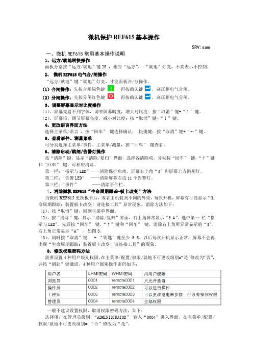
微机保护REF615基本操作SRV:sam一、微机REF615常用基本操作说明1、远方/就地转换操作面板分别按“远方/就地”键2S ,相应“远方”、“就地”灯亮,不亮表示不控制。
2、微机REF615电气合/闸操作“远方/就地”键“就地”灯亮,才能面板合/分操作。
(1)合闸操作:先按合闸绿色键,再按确认键,高压柜电气合闸。
(2)分闸操作:先按分闸红色键,再按确认键,高压柜电气分闸。
3、调整屏幕显示对比度操作(1)、屏幕亮看不到字体,调节屏幕暗度,增大对比度:按“取消”键+“↑”键。
(2)、屏幕暗,调节屏幕亮度,减小对比度:按“取消”键+“↓”键。
4、更改语言界面方法选择主菜单/语言,按“回车”键选择确认;快捷键:按“取消”键+“←”键。
5、查看事件、测量菜单可分别选择主菜单/事件、主菜单/测量,按“回车”键查看。
6、清除启动/跳闸/告警灯操作按“清除”键,显示“清除/复归”界面,选择各清除项,分别按“回车”键,“↑”键和“回车”键,可相应清除。
第一栏:“指示与LED”——清除保护启动、屏幕右上角“!”和屏幕上方跳闸灯。
第二栏;“告警LED”——清除屏幕右边11个告警灯。
第三栏;“事件”——清除事件栏。
7、消除微机REF615“生命周期跟踪-板卡改变”方法当微机REF615更换板卡后,或者主机装到不同的外壳,每次开机,屏幕有可能显示“生命周期跟踪:装置板卡改变!请连接工具”异常现象。
消除方法如下:(1)、按“取消”键,回到主菜单界面。
(2)、按“清除”键,显示“清除/复归”界面,右上角异常显示“!A”。
选中第一栏“指示与LED”,先后按“回车”键,“↑”键和“回车”键,消除右上角所异常显示的“!”,右上角正常显示“A”,如图3。
(3)、同时按“取消”键 + “钥匙”键至少5 S。
以后每次开机显示正常,屏幕不会再出现“生命周期跟踪:装置板卡改变!请连接工具”的现象。
8、修改权限密码方法需要设置4种用户级别权限,在主菜单/配置/权限/就地不可更改级别=“是”修改为“否”,并按“钥匙”键激活,4种用户级别操作密码如下:一般不建议设置权限,取消权限密码方法,如下:选择用户在管理员级别,“ADMINISTRATOR”输入“0004”进入界面,在主菜单/配置/权限/就地不可更改级别= “否”修改为“是”。

Line differential protection and control RED615Compact and versatile solution for utility and industrial power distribution systemsRelion ®615 seriesIdeal selectivity for two-end line differential protectionRED615 is a phase-segregated, two-end line differential protection and control relay for protection, control, measurement and supervision in utility and industrial power distribution systems, including radial, looped and meshed distribution networks, with or without distributed power generation. RED615 is also ideal for line differential applications with an in-zone transformer. RED615 relays communicate between substations either over a fiber-optic link or a galvanic pilot wire connection.ApplicationRED615 has been designed to be the main protectionfor overhead line and cable feeders, in either isolated neutral, resistance-earthed, compensated or effectively earthed distribution networks, depending on the standard configuration.RED615 is available in five standard configurations, one of which is a plain line differential protection with overcurrent backup protection two with added earth-fault protection functionality in particular, and another two further extended with directional overcurrent as well as phase-voltage and frequency-based protection. Switch on to fault is now introduced in all standard configurations and voltage unbalance in the two extended ones. They both also include a fault locator which locates short circuits in radial distribution networks and earth faults in effectively and low-resistance earthed ones. If the fault current is as high as or higher than the load current, earth faults in isolated neutral distribution networks will also be located. In addition, one of the two extended standard configurations includes support for three combi-sensor inputs for phase currents (Rogowski coil)and voltages (voltage divider), whereas the other supports conventional current and voltage instrument transformers as the rest of the standard configurations.Two RED615 relays interconnected over a communication link form an entirely selective unit protection scheme. Protection of ring-type and meshed distribution networks generally requires unit protection solutions, also applied in radial networks containing distributed power generation.The standard configurations can be tailored to meet application-specific requirements using the IEC 61850-compliant Protection and Control IED Manager PCM600. Human-machine interfaceAs a member of the Relion® product family, RED615 shares the same human-machine interface (HMI) look and feel as the other Relion protection and control relays and IEDs. The same look and feel includes the location of a push button with a certain function and the menu structure.RED615 is equipped with a large graphical display whichcan show customizable single-line diagrams (SLD) with position indication for the circuit breaker, disconnectors and the earthing switch. Also measured values provided by the chosen standard configuration can be displayed. The SLDs are customized using PCM600 and can have multiple pages for easy access to selected information. The SLDs can be accessed not only locally but also via the web browser-based HMI that has now been enriched with a number of usability enhancing features.Standardized communicationRED615 fully supports the IEC 61850 standard for communication and interoperability of substation automation devices, including fast GOOSE messaging and now alsoIEC 61850-9-2 LE and Edition 2, offering substantial benefits in terms of extended interoperability. The line differential relay further supports the DNP3, IEC 60870-5-103 and Modbus®protocols, now introducing also the parallel redundancy protocol (PRP) and the high-availability seamless redundancy (HSR) protocol. With the protocol adapter SPA-ZC 302, Profibus DVP1 can also be used. RED615 is able to use two communication protocols simultaneously.For redundant Ethernet communication, RED615 offers two optical Ethernet network interfaces. The redundant Ethernet solution can be built on the Ethernet-based IEC 61850, Modbus® and DNP3 protocols.The implementation of the IEC 61850 standard in RED615 covers both vertical and horizontal communication, including GOOSE messaging with both binary and analog signalsas well as parameter setting according to IEC 61850-8-1.In addition, IEC 61850-9-2 LE process bus with sending sampled values of both analog voltages and currents and receiving sampled values of voltages is introduced. The sampled values can also be used for synchro-check, bothin conventional instrument transformer and sensor-based applications, to ensure safe interconnection of two networks. For process bus applications, which require high-accuracy time synchronization, IEEE 1588 V2 is used, with a time stamp resolution of not more than four microseconds.IEEE 1588 V2 is supported in all variants with a redundant Ethernet communication module. In addition, RED615 supports synchronization over Ethernet using SNTP or over a separate bus using IRIG-B.Main benefits−Withdrawable plug-in unit design for swift installation and testing−Selective unit protection as phase-segregated two-end line differential protection, either with sensors or conventional2 Line-differential protection and control | RED615Protection function overview of the E configuration of RED615.instrument transformers−Ready-made standard configurations, including line differ-ential communication, for fast and easy setup with tailoring capabilities−Line differential communication between substations either over a fiber-optic link or a galvanic pilot wire connection−Ideal for line differential applications with an in-zone trans-former−IEC 61850 Edition 2 and Edition 1 support, including HSR and PRP, GOOSE messaging and IEC 61850-9-2 LE for less wiring and supervised communication−IEEE 1588 V2 for high-accuracy time synchronization and maximum benefit of substation-level Ethernet communica-tion−Large graphical display for showing customizable SLDs, accessible either locally or through a web browser-based HMI 615 seriesRED615 is a member of ABB’s Relion product family and part of its 615 protection and control series of relays, characterized by compactness and withdrawable plug-in unit design. In addition to RED615, the 615 series includes the following relays:−REF615 Feeder protection and control−RET615 Transformer protection and control−REU615 Voltage protection and control−REM615 Motor protection and control−REV615 Capacitor bank protection and controlLife cycle servicesLife cycle services ABB offers full support for all protection and control relays throughout their entire lifecycle. Our extensive life cycle services include training, customer support, maintenance and modernization.RED615 | Line-differential protection and control 34 Line-differential protection and control | RED615Supported functions, codes and symbols Functionality ProtectionThree-phase non-directional overcurrent protection, low stage Three-phase non-directional overcurrent protection, high stageThree-phase non-directional overcurrent protection, instantaneous stage Three-phase directional overcurrent protection, low stage Three-phase directional overcurrent protection, high stage Non-directional earth-fault protection, low stage Non-directional earth-fault protection, high stageNon-directional earth-fault protection, instantaneous stage Directional earth-fault protection, low stage Directional earth-fault protection, high stage Admittance based earth-fault protection Wattmetric based earth-fault protection Transient / intermittent earth-fault protection Harmonics based earth-fault protectionNon-directional (cross-country) earth fault protection, using calculated Io Negative-sequence overcurrent protection Phase discontinuity protection Residual overvoltage protection Three-phase undervoltage protection Three-phase overvoltage protection Positive-sequence undervoltage protection Negative-sequence overvoltage protection Frequency protectionThree-phase thermal protection for feeders, cables and distribution transformers Three-phase thermal overload protection for power transformers, two time constants Binary signal transferCircuit breaker failure protection Three-phase inrush detector Switch onto fault Master tripMulti-purpose protection Fault locatorLine differential protection with in zone power transformer High impedance fault detectionStandard configurations DescriptionLine differential protectionLine differential protection with directional earth-fault protection and circuit breaker condition monitoring Line differential protection with non-directional earth-fault protection and circuit breaker condition monitoring Line differential protection with directional overcurrent and earth-fault protection, voltage and frequency based protection and measurements, synchro-check and circuit-breaker condition monitoring (RTD option, optional power quality and fault locator)Line differential protection with directional overcurrent and earth-fault protection, voltage and frequency based protection and measurements, circuit-breaker condition monitoring (sensor inputs, optional power quality, fault locator and synchro-check with IEC 61850-9-2LE)Standard configurationA B CD E Standard configurationsRED615 | Line-differential protection and control 5B 121-----21)1 1)(3) 1) 3)(3) 1) 3)1 4)(1) 3) 4) 1213 1)- - --- 111111218 -11E - -121 - - -2 2)1 2)(3) 2) 3)(3) 2) 3)1 2) 4)(1) 3) 4) 1213 2)33114111111218(1)1-A 121-----------2---------11 5)11218-11D - - 121-- - 21(3) 3)(3) 3)1 4)(1) 3) 4) 121333114111111218(1)11IEC-ANSI 51P-151P-250P/51P 67-167-251N-151N-2 50N/51N 67N-167N-221YN 32N 67NIEF 51NHA 51N-24646PD 59G 275947U+47O-8149F 49T/G/C BST51BF/51NBF 68SOTF 94/86MAP 21FL 87L HIZC 121--211-----(1) 3) 4) -21- -- -- - 111111218 -11IEC 606173I>3I>> 3I>>>3I> ->3I>> -> Io>Io>> Io>>>Io> ->Io>> ->Yo> ->Po> ->Io> -> IEF Io>HA Io>>I2>I2/I1>Uo>3U<3U>U1<U2>f>/f<,df/dt 3Ith>F 3Ith>T/G/C BST 3I>/Io>BF 3I2f>SOTF Master Trip MAP FLOC 3Id/I>HIFIEC 61850PHLPTOC PHHPTOC PHIPTOC DPHLPDOC DPHHPDOC EFLPTOC EFHPTOC EFIPTOC DEFLPDEF DEFHPDEF EFPADM WPWDE INTRPTEF HAEFPTOC EFHPTOC NSPTOC PDNSPTOC ROVPTOV PHPTUV PHPTOV PSPTUV NSPTOV FRPFRQ T1PTTR T2PTTR BSTGGIO CCBRBRF INRPHAR CBPSOF TRPPTRC MAPGAPC SCEFRFLO LNPLDF PHIZ1, 2,... = number of included instances / I/Os( ) = optionalSupported functions, codes and symbolsFunctionalityPower QualityCurrent total demand distortionVoltage total harmonic distortionVoltage variationVoltage unbalanceControlCircuit-breaker controlDisconnector controlEarthing switch controlDisconnector position indicationEarthing switch indicationAuto-reclosingSynchronism and energizing checkCondition MonitoringCircuit-breaker condition monitoringTrip circuit supervisionCurrent circuit supervisionFuse failure supervisionProtection communication supervisionRuntime counter for machines and devicesMeasurementDisturbance recorderLoad profile recordFault recordThree-phase current measurementSequence current measurementResidual current measurementThree-phase voltage measurementResidual voltage measurementSequence voltage measurementThree-phase power and energy measurementRTD/mA measurementFrequency measurementIEC 61850-9-2 LE sampled value sending 7) 8)IEC 61850-9-2 LE sampled value receiving (voltage sharing) 7) 8) 6 Line-differential protection and control | RED615RED615 | Line-differential protection and control 7B ----12132(1)121-11111111-1------D (1) 6)(1) 6)(1) 6)(1) 6)12132(1)11211111111112111(1)1(1)(1)A ----12132--21-1111111---------IEC 61850CMHAI VMHAI PHQVVR VSQVUB CBXCBR DCXSWI ESXSWI DCSXSWI ESSXSWI DARREC SECRSYN SSCBR TCSSCBR CCRDIF SEQRFUF PCSRTPC MDSOPT RDRE LDPMSTA FLTRFRC CMMXU CSMSQI RESCMMXU VMMXU RESVMMXU VSMSQI PEMMXU XRGGIO130FMMXU SMVSENDER SMVRCVIEC-ANSI PQM3I PQM3V PQMV PQMUBV I ↔ O CB I ↔ O DCC I ↔ O ESC I ↔ O DC I ↔ O ES 7925CBCM TCM MCS 3I 60PCS OPTM DFR LOADPROF FAULTREC 3I I1, I2, I0In 3V Vn V1, V2, V0P , E X130 (RTD)fSMVSENDER SMVRCVIEC 60617PQM3I PQM3U PQMU PQMUBU I ↔ O CB I ↔ O DCC I ↔ O ESC I ↔ O DC I ↔ O ES O → I SYNC CBCM TCS MCS 3I FUSEF PCS OPTS DR LOADPROF FAULTREC 3I I1, I2, I0Io 3U Uo U1, U2, U0P , E X130 (RTD)fSMVSENDER SMVRCVC ----12132(1)121-11111111--------E (1) 6)(1) 6)(1) 6)(1) 6)12132(1)(1) 7)1211111111211 (2) 7)-11-1(1)(1)1) “Uo measured” is always used.2)“Uo calculated” is always used.3)One of the following can be ordered as an option: admittance-based E/F, wattmetric-based E/F or harmonics-based E/F.4)“Io measured” is always used.5)“Io calculated” is always used.6)Power quality option includes current total demand distortion, voltage total harmonic distortion, voltage variation and voltage unbalance.7)Available only with IEC 61850-9-28)Available only with COM0031-00371, 2,... = number of included instances / I/Os( ) = optionalContact us1M R S 756489 H , 5.0 F P 1 © C o p y r i g h t 2015 A B B . A l l r i g h t s r e s e r v e d .For more information, please refer to RED615 Product Guide, or contact us:ABB Oy, Medium Voltage Products Distribution Automation P .O. Box 699FI-65101 VAASA, Finland Phone: +358 10 22 11Fax: +358 10 22 41094ABB India Limited, Distribution Automation Maneja WorksVadodara – 390013, India Phone: +91 265 272 4402Fax: +91 265 263 8922/mediumvoltage/substationautomation。

RED615 v1.1 中文版产品通告我们很高兴地通知大家,线路差动保护继电器 RED615 1.1 中文版正式发布。
RED615 是 ABB 615 产品系列的成员,它是一种分相线路差动保护继电器(智能保护和测控装置),专为电力系统和工业配电网而设计,包括闭环和多电源供电系统。
615 系列继电器是根据 IEC 61850 规约在全新平台上研发和设计的。
这使产品从根本上支持站内设备互操作与水平通讯等特性,而不必通过附加的通讯模块。
RED615 可为配电网络中架空线和馈线提供分相纵联差动保护。
两台 RED615 通过专有通讯信道互联,形成具可选择性保护方案。
该保护常用于环网或多电源供电系统,同样也可用于带有发电机的辐射状电网系统。
标准配置产品新特性该继电器提供两段分相线路差动保护、过电流保护、负序电流保护和断路器失灵保护。
同时还具有自保持和抑制二次谐波涌流的功能。
除了保护功能外,RED615 还提供可远方/就地切换的断路器控制功能。
●两段分相线路纵联差动保护●内嵌 IEC 61850 通讯标准,支持 GOOSE 信息●通过专有通讯信道互联,形成具可选择性保护方案,为未来发展做好准备●故障录波功能得到提高,可采集12个交流量通道和 64 个开关量通道●获得专利的插拔式硬件设计方案,大大缩短日常测试和维修更换时间●唯一的 PCM 600 调试工具可实现继电器定值整定,信号配置和故障录波处理线路差动保护继电器 RED615 目前只提供一个标准配置版本,详情请见下表。
RED615 支持 IEC 61850 通讯规约从而真正实现站内设备间互相通讯,同时也支持流行的工业标准 Modbus 通讯协议。
继电器支持以太网RJ-45接口(100BASE-TX ),玻璃光纤 ST 接口,同时还支持 9 针的 RS-485 接口。
RED615 按照 IEC 61850 规约设计,包括垂直和水平通讯——继电器到继电器间的相互水平通讯(GOOSE )并符合 IEC 61850-8-1 的各项规范。

Feeder Protection REF615 Protection and ControlABB2Area of applicationREF615 is a dedicated feeder protection relay perfectly aligned for the protection, measurement and supervision of utility substations and industrial power systems. Re-engineered from the ground up, the new feeder protection relay has been designed to unleash the full potential of the IEC 61850 standard for communication and interoperability of substation automation devices.REF615 provides main protection for overhead lines, cable feeders and busbar systems of distribution substations. The feeder protection relay suits anydistribution network, regardless of the applied power system earthing principle.Protection and controlThe feeder protection relay offers short-circuit, timeovercurrent and thermal overload protection. The relay also features directional and non-directional earth-fault protection, sensitive earth-fault protection (SEF) and transient-measuring earth-fault protection including detection of intermittent earth-faults in cable networks. Finally, the relay incorporates a fl exible three-phase multi-shot auto-reclose function for automatic extinguishing of arc faults on open-wire overhead lines.Enhanced with an optional plug-in card, the relay offers a three-channel arc-fault protection system for supervision of the switchgear CB, cable and busbar compartment.REF615 also integrates basic control functionality, which facilitates the control of one circuit breaker via the relay’s HMI or remote control system. To protect the relay from unauthorized access and to maintain the integrity of information, the relay has been provided with a four-level, role-based user authentication system, with individual passwords for the viewer, operator, engineer and administrator level. The access control system applies to the front panel HMI, the web browser based HMI and the PCM600 relay setting and confi guration tool.The power of communicationREF615 supports the new IEC 61850 standard for inter-device communication in substations. The relay also sup-ports the industry standard Modbus ® protocol.The implementation of the IEC 61850 substation commu-nication standard in REF615 encompasses both vertical and horizontal communication, including GOOSE mes-saging and parameter setting according to IEC 61850-8-1. The substation confi guration language enables the use of engineering tools for automated confi guration, commis-sioning and maintenance of substation devices.IEC 61850-based Connectivity andInteroperability for Distribution SubstationsABB3Pre-emptive condition monitoringFor continuous control of the operational availability of the relay REF615 features a comprehensive choice of monitoring functions to supervise the relay itself, the CB trip circuit and the circuit breaker. Depending on the chosen device confi guration, the relay monitors the wear and tear of the circuit breaker, the spring charging time of the CB operating mechanism and the gas pressure of the breaker chambers. The relay also supervises the breaker travel time and the number of CB operations to provide basic information for scheduling CB maintenance.Rapid set-up and commissioningDue to the ready-made adaptation of REF615 for theprotection of feeders, the relay can be rapidly set up and commissioned, once it has been given the application-specifi c relay settings. If the relay needs to be adapted to the special requirements of the intended application, the fl exibility of the relay allows the relay’s standard signal confi guration to be adjusted by means of the signal ma-trix tool (SMT) included in the PCM600 relay setting and confi guration tool.By means of Connectivity Packages holding complete descriptions of ABB’s protection relays, with data signals, parameters and addresses, the relays can be automatically confi gured via MicroSCADA Pro system or the PCM600 relay setting and confi guration tool.Unique Plug-in design relayThe plug-in type relay design speeds up installation and testing of the protection. The factory-tested relay units can be withdrawn from the relay cases during switchgear factory and commissioning tests. The plug-in design also speeds up maintenance work thanks to the easy ex-change of relay units.The relay case provides automatic short-circuiting of the CT secondary circuits to prevent hazardous voltages from arising in the CT circuits when a relay plug-in unit is withdrawn from its case.The pull-out handle locking the relay unit into its case can be sealed to prevent the unit from being unintention-ally withdrawn from the relay case.REF615 highlights⏹ Directional & non-directional earth-fault protection, sensitive earth-fault protection, and transient-measuring earth-fault protection also covering intermittent earth-faults on cable feeders ⏹ Device connectivity and system inter-operability according to the IEC 61850 standard for next generation substation communication ⏹ Enhanced disturbance recorderfunctionality including high sampling frequency, extended length of records, 8 analog and 32 binary channels and fl exible triggering possibilities ⏹ Super-fast, three-channel arc-fault protection for increased personal safety, reduced material damage and minimized system down-time ⏹ Total control of the operationalcapability of the protection systemthrough extensive condition monitoring of the relay and the associated primary equipment ⏹ Plug-in type relay unit and a uniquerelay case design for a variety ofmounting methods and fast installation, routine testing and maintenance ⏹ One single tool for managing relaysettings, signal confi guration and disturbance handlingABB OyDistribution Automation P . O. Box 699FI-65101 VAASA, Finland Phone: +358 10 22 11Fax: +358 10 41 094/substationautomationP r i n t e d i n F i n l a n d 12/2007 1M R S 756381● = included, ❍ = optionalREF615 Technology SummaryTechnical details are available in the REF615 Product Guide 1MRS756379©C o p y r i g h t 2007 A B B . A l l r i g h t s r e s e r v e d . T h e i n f o r m a t i o n i n t h i s d o c u m e n t i s s u b j e c t t o c h a n g e w i t h o u t n o t i c e .Energizing inputsThree phase currents: 1/5 AOne residual current: 1/5 A or 0.2/1 A One residual voltage: 100/110/115/120 V Rated frequency: 50/60 Hz Binary inputs and outputsThree binary inputs with common groundOne additional binary input if no U 0 measurement Two NO double pole outputs with TCS Two NO single pole outputs Two change over signal outputs One signal output for IRFSeven binary inputs plus three binary outputs (avail-able with standard configurations B and D)CommunicationIEC 61850-8-1 with GOOSE messaging MODBUS TCP and RTU (optional)Time synchronization over station bus, SNTP over TCP/IPAuxiliary voltageVariant 1: 48 ... 250 V dc, 100 … 240 V ac Variant 2: 24 ... 60 V dc Dimensions177 mm (4U) height, 177 mm (4U) width, 140 mm depth, weight 3.5 kg ToolsProtection and Control IED Manager PCM600 ver. 2.0 for setting, signal configuration and disturbance handlingWeb browser based user interface (IE 7.0 or later)。
馈线保护测控装置REF615产品指南目 录1概述...............................................................12标准配置........................................................13保护功能........................................................34应用...............................................................75控制功能......................................................106测量.............................................................107故障录波......................................................108事件记录......................................................109故障数据记录...............................................1010断路器监视..................................................1011跳闸回路监视...............................................1112自检功能......................................................1113VT熔丝断线监视..........................................1114电流回路监视.. (1115)访问控制 (11)16输入和输出装置...........................................1217通信.............................................................1318技术数据......................................................1419显示选项......................................................3620安装方法......................................................3721外壳和插件单元...........................................3722选机及订货号...............................................3823配件及其订货号...........................................4224工具.............................................................4225ABB采用的解决方案....................................4426接线图..........................................................4527认证.............................................................4828参考资料 (4829)功能、代码和符号 (49)免责声明本文信息可能会更改,恕不另行通知。
同时,本文的信息不应被视为厦门 ABB 输配电自动化设备有限公司的承诺。
厦门 ABB 输配电自动化设备有限公司对此文件中可能会出现的错误不承担任何责任。
Copyright © 2008 厦门 ABB 输配电自动化设备有限公司版权所有。
商标ABB 是 ABB 集团的注册商标。
本文件中提及的所有其他品牌或产品名称可能是其持有者的商标或注册商标。
馈线保护测控装置REF615产品版本:2.01YZA000042产品版本:D/2009.4.30馈线保护测控装置REF615产品版本:2.01YZA0000421. 概述馈线保护测控装置 REF615 可为电力系统和工业配电网提供保护、控制、测量和监视功能。
该继电器是根据 IEC 61850 规约在全新平台上研发和设计的。
这使产品从根本上支持站内设备互操作与水平通信等特性,而不必通过附加的通信模块。
该装置可作为配网架空线和馈线的主保护,也可在要求保护与控制功能分开或者要求冗余保护的系统中作为后备保护。
根据预先的配置,该装置可用于中性点不接地、电阻性接地、补偿性接地和直接接地的网络,以及架空线和电缆馈线。
用户在配置完成后即可直接投入使用。
该装置支持多种通信规约,含GOOSE信息的IEC 61850、IEC 60870-5-103/Modbus。
2.标准配置馈线保护测控装置REF615有七种可选的标准配置,下表列出了不同配置所支持的功能。
表1 标准配置表2 所支持的功能ABB1馈线保护测控装置1YZA000042REF615产品版本:2.0ABB 2馈线保护测控装置REF615产品版本:2.01YZA0000421)基本联锁功能:断路器合闸通过开关量输入信号实现。
实际的联锁方案在继电器外部执行。
作为“主联锁输入量”的开关量被置1后可直接释放断路器闭锁,从而使之合闸。
2)扩展联锁功能:断路器联锁方案在继电器内部执行,基于主设备位置信息(通过开关量输入信号)和可用的逻辑功能。
PCM600 的信号矩阵工具(SMT)可用于修改联锁方案以适合用户需求。
● = 已包括,○ = 订购时可选3. 保护功能REF615馈线保护测控装置可提供过流保护、带时限的过流保护和热过负荷保护,亦可为馈线电缆提供带方向和无方向的接地保护、灵敏接地保护(SEF)、断相保护、瞬时接地保护、过电压和低电压保护、零序过压保护、正序低电压和负序过压保护。
除此之外,该装置还提供可灵活配置的多轮次重合闸功能,以用于保护架空线路。
REF615可通过可选配件配置三个弧光检测通道,可实现对金属铠装开关柜的电缆隔室、母线和断路器的弧光保护。
可选通信模块上配置了弧光保护传感器。
一旦监测对象产生电弧光故障,弧光保护即可快速动作从而为人身安全提供了保障,并将电弧故障对开关设备的损坏降到最小程度。
ABB3ABB4馈线保护测控装置REF615产品版本:2.01YZA000042图1:标准配置A 和B 的保护功能总览1) 可选图2:标准配置C 和D 的保护功能总览1) 可选ABB5馈线保护测控装置REF615产品版本:2.01YZA000042图4:标准配置F的保护功能总览1) 可选图3:标准配置E的保护功能总览1) 可选馈线保护测控装置1YZA000042REF615产品版本:2.01) 可选图5:标准配置J的保护功能总览ABB 6馈线保护测控装置REF615产品版本:2.01YZA0000424. 应用REF615馈线保护测控装置具有方向或无方向接地保护功能。
方向接地保护主要用于不接地或补偿网络中;无方向接地保护则用于接地或低阻抗网络中。
在输出馈线有相电流互感器、磁平衡电流互感器和零序电压测量装置的条件下,标准配置A和B可提供方向接地保护功能。
REF615可通过三相电流计算出零序电流从而支持(越野式)双相同时接地保护。
该继电器还具有间歇性接地保护功能。
标准配置C和D为馈线(包含相电流互感器)提供无方向接地保护。
接地保护的零序电流量由相电流得出。
在具体应用过程中尤其是需要灵敏接地保护时,磁平衡电流互感器可用于测量零序电流。
标准配置E和F提供了带相电压测量功能的无方向过流及方向接地保护。
此外,标准配置E和F还包括电流回路监视和带母线电压测量的进线VT熔丝断线监视功能。
标准配置F相比E还额外提供方向过流保护,过压和低电压保护,正序低电压和负序过压保护,以及零序电压保护。
图6:应用标准配置A或B的变电站过流和接地保护。
在进线间隔中,未使用的保护功能没有颜色并有虚线轮廓标记。
装置配备的弧光保护功能可实现对整个开关柜设备的快速且有选择性保护。
ABB7ABB8馈线保护测控装置REF615产品版本:2.01YZA000042图7:应用标准配置C或D的变电站过流和接地保护。
在进线间隔中,未使用的保护功能没有颜色并有虚线轮廓标记。
母线保护是根据联闭锁原理:当馈线的过流保护启动时即闭锁进线的瞬时速断保护。
在没有闭锁信号的情况下,进线过流保护将清除开关柜/母线故障。
1) 可选1) 可选图8:两条进线的保护与控制功能由继电器标准配置F实现。
合上母线刀闸即可使两条进线并联。
方向过流保护的分段可实现选择性过流保护。
馈线主备保护通过零序过压保护分段实现。
相低电压保护和过压保护可用于跳闸或告警。
5.控制功能装置面板上的分闸和合闸按钮可实现对断路器的控制。
应用所需的联锁方案通过 PCM600中的信号矩阵工具(SMT)配置。
6.测量装置持续测量相电流、电流的对称分量以及零序电流。
如带有电压测量功能,该装置还可测量零序电压,相电压和电压序分量。
此外,装置还可计算用户可选预设时限内的最大需求值、保护对象的热过负荷,以及基于负序和正序电流之间的比率计算相不平衡值。
测量值可通过继电器前面板上的用户接口就地访问或通过继电器的通信接口远程访问,还可以基于网页浏览器实现远程或者就地访问。
7.故障录波装置具有故障录波功能:可记录 12 个模拟信号通道和 64 个开关量信号通道;可设置模拟量通道来记录测量电流和电压的波形或趋势;此外可以设置模拟量通道在测量值低于或超过设定值时触发记录功能。
开关量信号通道可在开关量信号的上升沿或下降沿或既在上升沿也在下降沿时开始记录。
根据缺省设置,开关量通道的设置用于记录装置外部或内部信号,例如起动或跳闸信号,或外部闭锁或控制信号。
装置开关量诸如保护起动或跳闸信号,通过开关量输入的外部控制信号可以触发录波功能。
以此记录的信息存储在非易失内存中并可上传作后续故障分析。
8.事件记录为了搜集事件顺序(SoE)信息,装置内置一非易失内存可存储50条带时标的事件代码。
非易失内存可在装置临时掉电时仍能保存事件记录。
事件记录为馈线故障和干扰的故障预防和事后提供详细数据支持。
事件顺序信息可通过继电器前面板上的用户接口进行就地访问,或通过装置的通信接口远程访问,还可以基于网页浏览器实现远程或就地访问。