RAC05-05SA;RAC05-12SA;RAC05-15SA;RAC05-24SA;RAC05-3.3SA;中文规格书,Datasheet资料
- 格式:pdf
- 大小:161.58 KB
- 文档页数:3
宏晶单片机STC12C5052AD单片机 2008-01-30 18:07:32 阅读122 评论0字号:大中小订阅介绍ISP操作,ADC,看门狗,工作模式(掉电,空闲)//----------------------工作频率:0~35MHz,相当于普通8051:0~420MHz--- 实际可到48MHz,相当于8051: 0~576MHz常温下内部R/C 振荡器频率为:5.2MHz ~ 6.8MHz精度要求不高时,可选择使用内部时钟,但因为有制造误差和温漂,应认为是4MHz ~8MHz256Byte SRAM,5K Flash程序存储器,512Byte×4个扇区的EEPROM (与程序存储区分开)STC12C2052AD 系列工作电压:5.5V - 3.4V加密性强, 无法解密, 超强抗干扰, 内部集成M A X 8 1 0 专用复位电路,超低功耗:1 、掉电模式:典型功耗 <0.1 μ A2 、空闲模式:典型功耗 <1.3mA3 、正常工作模式:典型功耗 2.7mA - 7mA4、掉电模式可由外部中断唤醒,适用于电池供电系统,如水表、气表、便携设备等。
//Keil C开发环境,Device选用Intel 8052AH#include <STC12C2052AD.H>#include <intrins.h> //_nop_()二,ISP操作//-----------------sub_ISP------------------void ISP_en(){EA = 0; // 关中断ISP_CONTR = 0x84; //1000.0100}void ISP_dis(){ISP_CONTR = ISP_CONTR & 0x7f; // 0111,1111ISP_TRIG = 0x00;EA = 1; // 开中断}unsigned char ISP_read(unsigned int c_address){ISP_en(); // 1000,0000 Enable ISPISP_ADDRH = (unsigned char)(c_address >> 8);ISP_ADDRL = (unsigned char)(c_address);ISP_CMD=0x01; // 0000,0001 ;读数据ISP_TRIG = 0x46;ISP_TRIG = 0xB9;_nop_();ISP_dis(); //Disable ISPreturn (ISP_DATA);}void ISP_erase(unsigned int c_address)//"扇区中任意一个字节的地址都是该扇区的地址,无需求首地址"{ISP_en(); // 1000,0000 Enable ISPISP_ADDRH = (unsigned char)(c_address >> 8); //0x1000,0x1200(STC12C4052) ISP_ADDRL = 0x00;ISP_CMD =0x03; // 0000,0011 ;扇区擦除ISP_TRIG = 0x46; // 触发ISP_IAP命令ISP_TRIG = 0xB9; // 触发ISP_IAP命令_nop_();ISP_dis(); //Disable ISP}void ISP_program(unsigned int c_address, unsigned char c_data){ISP_en(); // 1000,0000 Enable ISP dddddISP_ADDRH = (unsigned char)(c_address >> 8);ISP_ADDRL = (unsigned char)(c_address);ISP_CMD=0x02; // 0000,0010 ;编程ISP_DATA = c_data;ISP_TRIG = 0x46; // 触发ISP_IAP命令ISP_TRIG = 0xB9; // 触发ISP_IAP命令_nop_();ISP_dis(); //Disable ISP}三,AD转换unsigned char ADC_result(bit port) //1:p16; 0:p17{if(port){ADC_CONTR &= 0xFE;ADC_CONTR |= 0x06;//110:P16为作AD输入,改变AD输入口时需要加入延时 20~200us,使输入电压稳定}else{ADC_CONTR|=0x07;}c_delay(100);//若输入信号内阻在10K以下,可不加ADC_CONTR &= 0xE7; //1110,0111清ADC_FLAG ,停ADCADC_CONTR|=0x08; //0000.1000开始转换while((ADC_CONTR & 0x10) != 0x10); //转换结束 if-->whilereturn(ADC_DATA);}应用data_keyboard=ADC_result(1); //1:p16; 0:p17if(data_keyboard>150 && data_keyboard<158){//…}四,看门狗WDT_CONTR=0x3B;//0011.1011 启动看门狗pre_scale=16void C_T1() interrupt 3 using 2{wdt_i++;if(wdt_i>=10) //看门狗喂狗时间控制若取5.8MHz 溢出:1.08s,定时:1.03s{WDT_CONTR=0x3B;//0011.1011wdt_i=0;}TH1=init_th1;//#define init_th1 0x3C 50'000,取pre_scale=16,32768*16=524'288; >50'000*10次TL1=init_tl1; //#define init_tl1 0xB0TF1=0;TR1=1;}介绍ISP操作,ADC,看门狗,工作模式(掉电,空闲)//----------------------工作频率:0~35MHz,相当于普通8051:0~420MHz--- 实际可到48MHz,相当于8051: 0~576MHz常温下内部R/C 振荡器频率为:5.2MHz ~ 6.8MHz精度要求不高时,可选择使用内部时钟,但因为有制造误差和温漂,应认为是4MHz ~ 8MHz256Byte SRAM,5K Flash程序存储器,512Byte×4个扇区的EEPROM (与程序存储区分开)STC12C2052AD 系列工作电压:5.5V - 3.4V加密性强, 无法解密, 超强抗干扰, 内部集成M A X 8 1 0 专用复位电路,超低功耗:1 、掉电模式:典型功耗 <0.1 μ A2 、空闲模式:典型功耗 <1.3mA3 、正常工作模式:典型功耗 2.7mA - 7mA4、掉电模式可由外部中断唤醒,适用于电池供电系统,如水表、气表、便携设备等。

SNLS系列芯片名称74系列资料型号器件名称SN74LS00 四2输入端与非门SN74LS01 四2输入端与非门(OC)SN74LS02 四2输入端或非门SN74LS03 四2输入端与非门(OC)SN74LS04 六反相器SN74LS05 六反相器(OC)SN74LS06 六高压输出反相器(OC,30V)SN74LS07 六高压输出缓冲,驱动器(OC,30V)SN74LS08 四2输入端与门SN74LS09 四2输入端与门(OC)SN74LS10 三3输入端与非门SN74LS11 三3输入端与门SN74LS12 三3输入端与非门(OC)SN74LS13 双4输入端与非门SN74LS14 六反相器SN74LS15 三3输入端与门(OC)SN74LS16 六高压输出反相器(OC)SN74LS17 六高压输出缓冲,驱动器(OC)SN74LS19A HEX SCHMITT-TRIGGER INVERTERSSN74LS20 双4输入端与非门SN74LS21 双4输入端与门SN74LS22 双4输入端与非门(OC)SN74LS24A 施密特与非门/变换器SN74LS26 四2输入端高压输出与非缓冲器SN74LS27 三3输入端或非门SN74LS28 四2输入端或非缓冲器型号器件名称SN74LS30 8输入端与非门SN74LS31 HEX GENERATING DELAY LINESSN74LS32 四2输入端或门SN74LS33 QUAD 2-INPUT POSITIVE-NOR BUFFERS SN74LS37 QUAD 2-INPUT POSITIVE-NANDBUFFERSSN74LS38 QUAD 2-INPUT POSITIVE-NANDBUFFERSSN74LS40 双4输入端与非缓冲器SN74LS424线-10线译码器 SN74LS47BCD 七段译码,驱动器 SN74LS48BCD-TO-SEVEN-SEGMENT DECODERS/DRIVERS SN74LS49BCD-TO-SEVEN-SEGMENT DECODERS/DRIVERS SN74LS512路3-3输入,2路2-2输入与或非门 SN74LS544路2-3-3-2输入与或非门 SN74LS552路4-4输入与或非门 SN74LS56FREQUENCY DIVIDERS SN74LS57FREQUENCY DIVIDERS SN74LS68DUAL 4-BIT DECADE OR BINARY COUNTERS SN74LS69DUAL 4-BIT DECADE OR BINARY COUNTERS SN74LS73ADUAL J-K FLIP-FLOPS WITH CLEAR SN74LS74A双上升沿D 型触发器 SN74LS75QUAD BISTABLE LATCHES SN74LS76A单D 型触发器 SN74LS78A双D 型触发器 型号器件名称 SN74LS854位数值比较器 SN74LS86A四二进制原码/反码,0/1单元 SN74LS90DECADE COUNTER SN74LS918位移位寄存器 SN74LS92DIVIDE-BY-TWELVE DECADECOUNTER SN74LS934-BIT BINARY COUNTERS SN74LS95B4位移位寄存器 SN74LS96四2输入端与非门 SN74LS107A双 J-K 触发器 SN74LS109A4位移位寄存器 SN74LS112A双下降沿J-K 触发器 SN74LS114A双 J-K 触发器 SN74LS122RETRIGGERABLE MONOSTABLEMULTIVIBRATOR SN74LS123可重触发双稳态触发器 SN74LS125A四总线缓冲器 SN74LS126A四总线缓冲器 SN74LS132四2输入端与非门 SN74LS136QUAD 2-INPU T EXCLUSIVE-OR GATES 地址锁存,3线-8线译码器 3线-8线译码器 双2线-4线译码器SN74LS137SN74LS138SN74LS139ABCD-TO-DECIMAL DECODERS/DRIVERS 10线-4线优先编码器 8线-3线优先编码器 8选1数据选择器 双4选1数据选择器 双2线-4线译码器 双2线-4线译码器OC 四2选1数据选择器 四2选1数据选择器(反码输出) 十进制同步计数器4位二进制同步计数器 十进制同步计数器 4位二进制同步计数器 8位移位寄存器 8位移位寄存器 8位移位寄存器 4位二进制同步加/减计数器 4-BY-4 REGISTER FILES QUADRUPLE D-TYPE FLIP-FLOPS WITH CLEAR 4位D 型寄存器 六上升沿D 型发器 四上升沿D 型触发器 4位算述逻辑单元/函数生器 DUAL CARRY-SAFE FULL ADDERS 十进制加/减计数器 4位二进制加/减计数器 十进制加/减计数器(双时钟) 4位二进制加/减计数器(双时钟) 4位双向移位寄存器 4位移位寄存器 50/30/100-MHZ 可预置二-五-十进制计数器二-八-十六进制计数器 双单稳态触器 16 X 4 同步先入,先出存储器 16X4 SYNCHRONOUS FIFO MEMORY 16 X 4同步先入,先出存储器(OC ) 八反相缓冲/线驱动/线接收器 八缓冲/线驱动/线接收器 四总线收发器 四总线收发器 八缓冲/线驱动/线接收器 八双向总线发送/接发器4线-7段译码/高压输出驱动器SN74LS248 4线-7段译码/驱动器 SN74LS145SN74LS147SN74LS148SN74LS151SN74LS153SN74LS155ASN74LS156SN74LS157SN74LS158SN74LS160A SN74LS161ASN74LS162ASN74LS163ASN74LS164SN74LS165ASN74LS166ASN74LS169BSN74LS170SN74LS171SN74LS173ASN74LS174SN74LS175SN74LS181SN74LS183SN74LS190SN74LS191SN74LS192SN74LS193SN74LS194ASN74LS195ASN74LS196SN74LS197SN74LS221SN74LS222ASN74LS224ASN74LS227SN74LS228SN74LS240SN74LS241SN74LS242SN74LS243SN74LS244SN74LS245SN74LS247SN74LS251 8选1数据选择器SN74LS253 双4选1数据选择器SN74LS257B 四2选1数据选择器SN74LS258B 四2选1数据选择器SN74LS259B 8位可寻址锁存器SN74LS261 2 BY 4 BIT PARALLEL BINARY MULTIPLIER SN74LS266 QUAD 2-INPUT EXCLUSIVE-NOR GATESSN74LS273 八D触发器SN74LS279A QUAD /S-/R LATCHESSN74LS280 9位奇偶产生器/校验器SN74LS283 4位二进制超位全加器SN74LS290 ASYNCHRONOUS DECADE COUNTERSSN74LS292 可编程频率分配器/数字定时器SN74LS293 4-BIT 二进制计数器SN74LS294 可编程频率分配器/数字定时器SN74LS295B 4-BIT RIGHT-SHIFT LEFT-SHIFT REGISTERS SN74LS297 DIGITAL PHASE-LOCKED-LOOP FILTERSSN74LS298 QUADRUPLE 2-INPUT MULTIPLEXERSSN74LS299 8位双向通用移位/存储寄存器SN74LS320 CRYSTAL-CONTROLLED OSCILLATORSSN74LS321 CRYSTAL-CONTROLLED OSCILLATORSN74LS322A 8-BIT SHIFT REGISTERS WITH SIGN EXTEND SN74LS323 UNIVERSAL SHIFT / STORAGE REGISTERSSN74LS348 8线-3线优先编码器SN74LS352 双4选1数据选择器/多路(复用)器SN74LS353 双4选1数据选择器/多路(复用)器SN74LS354 8选1数据选择器/多路(复用)器/寄存器SN74LS355 8选1数据选择器/多路(复用)器/寄存器(OC)SN74LS356 8选1数据选择器/多路(复用)器/寄存器SN74LS365A 六总线驱动器SN74LS366A 六反相总线驱动器SN74LS367A 六总线驱动器SN74LS368A 六反相总线驱动器SN74LS373 六D型锁存器SN74LS374 六上升沿D型触发器SN74LS375 QUAD BISTABLE LATCHESSN74LS377 六上升沿D型触发器SN74LS378 HEX D-TYPE FLIP-FLOPSSN74LS379 QUAD D-TYPE FLIP-FLOPS算术逻辑单元/函数发生器 算术逻辑单元/函数发生器 8 BY 1 TWO'S-COMPLEMENT MULTIPLIERS QUAD SERIAL ADDERS/SUBTRACTORS 四2输入端异或门 双十进制计数器 双4位二进制计数器 CASCADABLE SHIFT REGISTERS OCTAL STORAGE REGISTERS QUADRUPLE 2-INPUT MULTIPLEXERS 可再触发单稳态多频振荡器 双可再触发单稳态多频振荡器 QUAD TRIDIRECTIONAL BUS TRANSCEIVERS QUAD TRIDIRECTIONAL BUS TRANSCEIVERS QUAD TRIDIRECTIONAL BUS TRANSCEIVERS QUAD TRIDIRECTIONAL BUS TRANSCEIVERS BCD-TO-DECIMAL DECODERS/DRIVERS QUADRUPLE BUS TRANSCEIVERS QUADRUPLE BUS TRANSCEIVERS OCTAL BUFFERS WITH 3-STATE OUTPUTS OCTAL BUFFERS OCTAL BUFFERS OCTAL BUFFERS ASYNCHRONOUS DECADE COUNTERS 8三态缓冲器(反相) OCTAL BUFFERS AND LINE DRIVERS 8-BIT BINARY COUNTERS 8-BIT BINARY COUNTERS 8-BIT BINARY COUNTERS 8-BIT BINARY COUNTERS SERIAL-IN SHIFT REGISTERS SERIAL-IN SHIFT REGISTERS SERIAL-IN SHIFT REGISTERS SERIAL-OUT SHIFT REGISTERS SHIFT REGISTERS WITH INPUT LATCHES 8-BIT SHIFT REGISTERS MEMORY REFRESH CONTROLLERS MEMORY REFRESH CONTROLLERS MEMORY REFRESH CONTROLLERS OCTAL 2-INPUT MULTIPLEXED LATCHES OSN74LS381ASN74LS382ASN74LS384SN74LS385SN74LS386ASN74LS390SN74LS393SN74LS395A SN74LS396SN74LS399SN74LS422SN74LS423SN74LS440SN74LS441SN74LS442SN74LS444SN74LS445SN74LS446SN74LS449SN74LS465SN74LS466SN74LS467SN74LS468SN74LS490SN74LS540SN74LS541SN74LS590SN74LS591SN74LS592SN74LS593SN74LS594SN74LS595SN74LS596SN74LS597SN74LS598SN74LS599SN74LS600ASN74LS601ASN74LS603ASN74LS604SN74LS606CTAL 2-INPUT MULTIPLEXED LATCHES OCTAL 2-INPUT MULTIPLEXED LATCHES 八总线收发器 八总线收发器 八总线收发器 电压控制振荡器 双电压控制振荡器 双电压控制振荡器 DUAL VOLTAGE-CONTROLLED OSCILLATORS 电压控制振荡器 双电压控制振荡器 16位平行误差检测修正电路 OCTAL BUS TRANSCEIVERS OCTAL BUS TRANSCEIVERS OCTAL BUS TRANSCEIVERS OCTAL BUS TRANSCEIVER/IOL=48MA 3-STATE OCTAL BUS TRANSCEIVERS OCTAL BUS TRANSCEIVERS OCTAL BUS TRANSCEIVERS OCTAL BUS TRANSCEIVERS OCTAL BUS TRANSCEIVERS AND REGISTERS OCTAL BUS TRANSCEIVERS AND REGISTERS OCTAL BUS TRANSCEIVERS AND REGISTERS OCTAL BUS TRANSCEIVERS AND REGISTERS OCTAL BUS TRANSCEIVERS AND REGISTERS OCTAL BUS TRANSCEIVERS AND REGISTERS OCTAL BUS TRANSCEIVERS AND REGISTERS SYNCHRONOUS UP/DOWN DECADE COUNTERS 可预置同步加减二进制计数器 4-BY-4 REGISTER FILES 4位通用移位寄存器/锁存器 4位通用移位寄存器/锁存器 SERIAL-IN SHIFT REGISTERS SERIAL-OUT SHIFT REGISTERS 4-BIT PARALLEL BINARY ACCUMULATOR 8位二进制或BCD 大小比较器 8位二进制或BCD 大小比较器 8位二进制或BCD 大小比较器 8-BIT MAGNITUDE/IDENTITY COMPARATORS 8位二进制或BCD 大小比较器 八位数据等值比较器 十进制同步计数器 二进制同步计数器 4位二进制同步计数器SN74LS607 SN74LS620 SN74LS621 SN74LS623 SN74LS624 SN74LS625 SN74LS626 SN74LS627 SN74LS628 SN74LS629 SN74LS630 SN74LS638 SN74LS639 SN74LS640 SN74LS640-1 SN74LS641 SN74LS642 SN74LS644 SN74LS645 SN74LS646 SN74LS647 SN74LS648 SN74LS649 SN74LS651 SN74LS652 SN74LS653 SN74LS668 SN74LS669 SN74LS670 SN74LS671 SN74LS672 SN74LS673 SN74LS674 SN74LS681 SN74LS682 SN74LS684 SN74LS685 SN74LS686 SN74LS687 SN74LS688 SN74LS690 SN74LS691 SN74LS693SN74LS696 SN74LS697 SN74LS699 同步加/减计数器4位二进制同步加/减计数器4位二进制同步加/减计数器。
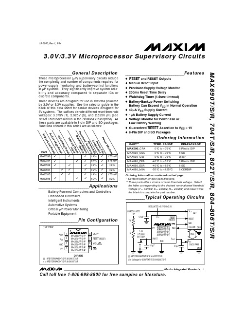
_______________General DescriptionThese microprocessor (µP) supervisory circuits reduce the complexity and number of components required for power-supply monitoring and battery-control functions in µP systems. They significantly improve system relia-bility and accuracy compared to separate ICs or discrete components.These devices are designed for use in systems powered by 3.0V or 3.3V supplies. See the selector guide in the back of this data sheet for similar devices designed for 5V systems. The suffixes denote different reset threshold voltages: 3.075V (T), 2.925V (S), and 2.625V (R) (see Reset Threshold section in the Detailed Description ). All these parts are available in 8-pin DIP and SO packages.Functions offered in this series are as follows:________________________ApplicationsBattery-Powered Computers and Controllers Embedded Controllers Intelligent Instruments Automotive SystemsCritical µP Power Monitoring Portable Equipment____________________________Featureso –R —E —S —E —T –and RESET Outputs o Manual Reset Inputo Precision Supply-Voltage Monitor o 200ms Reset Time Delayo Watchdog Timer (1.6sec timeout)o Battery-Backup Power Switching—Battery Can Exceed V CC in Normal Operation o 40µA V CC Supply Current o 1µA Battery Supply Currento Voltage Monitor for Power-Fail or Low-Battery Warningo Guaranteed –R —E —S —E —T –Assertion to V CC = 1V o8-Pin DIP and SO Packages______________Ordering InformationOrdering Information continued on last page.* Contact factory for dice specifications.** These parts offer a choice of reset threshold voltage. Select the letter corresponding to the desired nominal reset threshold voltage (T = 3.075V, S = 2.925V, R = 2.625V) and insert it into the blank to complete the part number.MAX690T/S/R, 704T/S/R, 802T/S/R, 804–806T/S/R3.0V/3.3V Microprocessor Supervisory Circuits________________________________________________________________Maxim Integrated Products 1__________________Pin Configuration_________Typical Operating CircuitsCall toll free 1-800-998-8800 for free samples or literature.19-0243; Rev 1; 9/94M A X 690T /S /R , 704T /S /R , 802T /S /R , 804–806T /S /R3.0V/3.3V Microprocessor Supervisory Circuits 2_______________________________________________________________________________________ABSOLUTE MAXIMUM RATINGSELECTRICAL CHARACTERISTICS(V CC = 3.17V to 5.5V for the MAX690T/MAX704T/MAX80_T, V CC = 3.02V to 5.5V for the MAX690S/MAX704S/MAX80_S, V CC = 2.72V to 5.5V for the MAX690R/MAX704R/MAX80_R; VBATT = 3.6V; T A = T MIN to T MAX ; unless otherwise noted. Typical values are at T A = +25°C.)Stresses beyond those listed under “Absolute Maximum Ratings” may cause permanent damage to the device. These are stress ratings only, and functional operation of the device at these or any other conditions beyond those indicated in the operational sections of the specifications is not implied. Exposure to absolute maximum rating conditions for extended periods may affect device reliability.Terminal Voltage (with respect to GND)V CC .........................................................................-0.3V to 6.0V VBATT....................................................................-0.3V to 6.0V All Other Inputs ...................-0.3V to the higher of V CC or VBATT Continuous Input CurrentV CC ..................................................................................100mA VBATT...............................................................................18mA GND..................................................................................18mA Output Current –R —E —S —E —T –, –P —F —O –....................................................................18mA V OUT ................................................................................100mAContinuous Power Dissipation (T A = +70°C)Plastic DIP (derate 9.09mW/°C above +70°C)..............727mW SO (derate 5.88mW/°C above +70°C)...........................471mW CERDIP (derate 8.00mW/°C above +70°C)...................640mW Operating Temperature RangesMAX690_C_ _/MAX704_C_ _/MAX80_ _C_ _........0°C to +70°C MAX690_E_ _/MAX704_E_ _/MAX80_ _E_ _......-40°C to +85°C MAX690_M_ _/MAX704_M_ _/MAX80_ _M_ _...-55°C to +125°C Storage Temperature Range.............................-65°C to +160°C Lead Temperature (soldering, 10sec).............................+300°CMAX690T/S/R, 704T/S/R, 802T/S/R, 804–806T/S/R3.0V/3.3V Microprocessor Supervisory Circuits_______________________________________________________________________________________3ELECTRICAL CHARACTERISTICS (continued)(V CC = 3.17V to 5.5V for the MAX690T/MAX704T/MAX80_T, V CC = 3.02V to 5.5V for the MAX690S/MAX704S/MAX80_S, V CC = 2.72V to 5.5V for the MAX690R/MAX704R/MAX80_R; VBATT = 3.6V; T A = T MIN to T MAX ; unless otherwise noted. Typical values are at T A = +25˚C.)M A X 690T /S /R , 704T /S /R , 802T /S /R , 804–806T /S /R3.0V/3.3V Microprocessor Supervisory Circuits 4_______________________________________________________________________________________Note 1: V CC supply current, logic input leakage, watchdog functionality (MAX690_/802_/805_/804_), M R functionality(MAX704_/806_), PFI functionality, state of –R —E —S —E —T –(MAX690_/704_/802_/806_), and RESET (MAX804_/805_) tested atVBATT = 3.6V, and V CC = 5.5V. The state of –R —E —S —E —T –or RESET and –P —F —O –is tested at V CC = V CC min.Note 2:Tested at VBATT = 3.6V, V CC = 3.5V and 0V. The battery current will rise to 10µA over a narrow transition window aroundV CC = 1.9V.Note 3:Leakage current into the battery is tested under the worst-case conditions at V CC = 5.5V, VBATT = 1.8V and at V CC = 1.5V,VBATT= 1.0V.Note 4:Guaranteed by design.Note 5:When V SW > V CC > VBATT, V OUT remains connected to V CC until V CC drops below VBATT. The V CC -to-VBATT comparatorhas a small 25mV typical hysteresis to prevent oscillation. For V CC < 1.75V (typ), V OUT switches to VBATT regardless of the voltage on VBATT.Note 6: When VBATT > V CC > V SW , V OUT remains connected to V CC until V CC drops below the battery switch threshold (V SW ).Note 7:V OUT switches from VBATT to V CC when V CC rises above the reset threshold, independent of VBATT. Switchover back toV CC occurs at the exact voltage that causes –R —E —S —E —T –to go high (on the MAX804_/805_, RESET goes low); however switchover occurs 200ms prior to reset.Note 8:The reset threshold tolerance is wider for V CC rising than for V CC falling to accommodate the 10mV typical hysteresis, whichprevents internal oscillation.Note 9:The leakage current into or out of the RESET pin is tested with RESET asserted (RESET output high impedance).ELECTRICAL CHARACTERISTICS (continued)(V CC = 3.17V to 5.5V for the MAX690T/MAX704T/MAX80_T, V CC = 3.02V to 5.5V for the MAX690S/MAX704S/MAX80_S, V CC = 2.72V to 5.5V for the MAX690R/MAX704R/MAX80_R; VBATT = 3.6V; T A = T MIN to T MAX ; unless otherwise noted. Typical values are at T A = +25˚C.)MAX690T/S/R, 704T/S/R, 802T/S/R, 804–806T/S/R3.0V/3.3V Microprocessor Supervisory Circuits_______________________________________________________________________________________55–60–2060140V CC -to-V OUT ON-RESISTANCEvs. TEMPERATURE14TEMPERATURE (°C)V C C -t o -V O U T O N -R E S I S T A N C E (Ω)20100–40080401203218020–60–2060140VBATT-to-V OUT ON-RESISTANCEvs. TEMPERATURE60TEMPERATURE (°C)V B A T T -t o -V O U T O N -R E S I S T A N C E (Ω)20100–40080401201401005025–60–2060140SUPPLY CURRENT vs. TEMPERATURE3045TEMPERATURE (°C)S U P P L Y C U R R E N T (µA )20100–4008040120403510,0000.1–60–2060140 BATTERY SUPPLY CURRENTvs. TEMPERATURE11000TEMPERATURE (°C)B A T T E R Y S U P P L YC U R R E N T (n A )20100–400804012010010 1.2401.230–60–2060140PFI THRESHOLD vs. TEMPERATURE1.2321.238TEMPERATURE (°C)P F I T H R E S H O L D (V)20100–40080401201.2361.234216196–60–2060140RESET TIMEOUT PERIOD vs. TEMPERATURE200212TEMPERATURE (°C)R E S E TT I M E O U T P E R I O D (m s )20100–40080401202082043010–60–2060140RESET-COMPARATOR PROPAGATIONDELAY vs. TEMPERATURE1426TEMPERATURE (°C)PR O P A G A T I O N D E L A Y (µs )20100–400804012022181.0040.994–60–2060140NORMALIZED RESET THRESHOLDvs. TEMPERATURE0.9961.002TEMPERATURE (°C)N O R M A L I Z E D R E S E T T H R E S H O L D (V )20100–40080401201.0000.998__________________________________________Typical Operating Characteristics(T A = +25°C, unless otherwise noted.)M A X 690T /S /R , 704T /S /R , 802T /S /R , 804–806T /S /R_______________Detailed DescriptionReset OutputA microprocessor’s (µP’s) reset input starts the µP in a known state. These µP supervisory circuits assert reset to prevent code execution errors during power-up, power-down, brownout conditions, or a watchdog timeout.–R —E —S —E —T –is guaranteed to be a logic low for 0V < V CC <V RST , provided that VBATT is greater than 1V. Withouta backup battery,–R —E —S —E —T –is guaranteed valid for V CC > 1V. Once V CC exceeds the reset threshold, aninternal timer keeps –R —E —S —E —T –low for the reset timeoutperiod; after this interval,–R —E —S —E —T –goes high (Figure 2).If a brownout condition occurs (V CC dips below thereset threshold),–R —E —S —E —T – goes low. Each time –R —E —S —E —T –is asserted, it stays low for the reset timeout period.Any time V CC goes below the reset threshold, the internal timer restarts.The watchdog timer can also initiate a reset. See the Watchdog Input section.The MAX804_/MAX805_ active-high RESET output is open drain, and the inverse of the MAX690_/MAX704_/MAX802_/MAX806_–R —E —S —E —T –output.Reset ThresholdThe MAX690T/MAX704T/MAX805T are intended for 3.3V systems with a ±5% power-supply tolerance and a 10% system tolerance. Except for watchdog faults,reset will not assert as long as the power supply remains above 3.15V (3.3V - 5%). Reset is guaranteed to assert before the power supply falls below 3.0V.The MAX690S/MAX704S/MAX805S are designed for 3.3V ±10% power supplies. Except for watchdog faults, they are guaranteed not to assert reset as long as the supply remains above 3.0V (3.3V - 10%). Reset is guaranteed to assert before the power supply falls below 2.85V (V CC - 14%).The MAX690R/MAX704R/MAX805R are optimized for monitoring 3.0V ±10% power supplies. Reset will not occur until V CC falls below 2.7V (3.0V - 10%), but is guaranteed to occur before the supply falls below 2.59V (3.0V - 14%).The MAX802R/S/T, MAX804R/S/T, and MAX806R/S/T are respectively similar to the MAX690R/S/T,MAX805R/S/T, and MAX704R/S/T, but with tightened reset and power-fail threshold tolerances.3.0V/3.3V Microprocessor Supervisory Circuits 6_____________________________________________________________________________________________________________________________________________________Pin Description1V OUT Supply Output for CMOS RAM. When V CC is above the reset threshold, V OUT isconnected to V CC through a P-channel MOSFET switch. When V CC falls below V SW and VBATT, VBATT connects to V OUT . Connect to V CC if no battery is used.2V CC Main Supply Input 3GND Ground4PFI Power-Fail Input. When PFI is less than V PFT or when V CC falls below V SW , –P —F —O –goeslow; otherwise, –P —F —O –remains high. Connect to ground if unused.7–R —E —S —E —T –Active-Low Reset Output. Pulses low for 200ms when triggered, and stays low wheneverV CC is below the reset threshold or when –M —R –is a logic low. It remains low for 200ms after either V CC rises above the reset threshold, the watchdog triggers a reset, or –M —R –goes from low to high.—–M —R–Manual Reset Input. A logic low on –M —R –asserts reset. Reset remains asserted as long as –M —R –is low and for 200ms after –M —R –returns high. This active-low input has an internal 70µA pull-up current. It can be driven from a TTL or CMOS logic line, or shorted to ground with a switch. Leave open if unused.6WDIWatchdog Input. If WDI remains high or low for 1.6sec, the internal watchdog timer runs out and reset is triggered. The internal watchdog timer clears while reset is asserted or when WDI sees a rising or falling edge. The watchdog function cannot be disabled.5–P —F —O –Power-Fail Output. When PFI is less than V PFT , or V CC falls below V SW , –P —F —O –goes low;otherwise, –P —F —O –remains high. Leave open if unused.8VBATTBackup-Battery Input. When V CC falls below V SW and VBATT, V OUT switches from V CC to VBATT. When V CC rises above the reset threshold, V OUT reconnects to V CC . VBATT may exceed V CC . Connect to V CC if no battery is used.—RESET Active-High, Open-Drain Reset Output is the inverse of –R —E —S —E —T –.NAMEFUNCTIONMAX690MAX80212PIN34——6587MAX804MAX805123476—58—MAX704MAX806Watchdog Input(MAX690_/802_/804_/805_)The watchdog circuit monitors the µP’s activity. If the µP does not toggle the watchdog input (WDI) within 1.6sec,a reset pulse is triggered. The internal 1.6sec timer is cleared by either a reset pulse or by a transition (low-to-high or high-to-low) at WDI. If WDI is tied high or low, a –R —E —S —E —T –pulse is triggered every 1.8sec (t WD plus t RS ).As long as reset is asserted, the timer remains cleared and does not count. As soon as reset is deasserted,the timer starts counting. Unlike the 5V MAX690 family,the watchdog function cannot be disabled.Power-Fail ComparatorThe PFI input is compared to an internal reference. IfPFI is less than V PFT ,–P —F —O –goes low. The power-fail comparator is intended for use as an undervoltage detector to signal a failing power supply. However, the comparator does not need to be dedicated to this function because it is completely separate from the rest of the circuitry.The power-fail comparator turns off and –P —F —O –goes low when V CC falls below V SW on power-down. The power-fail comparator turns on as V CC crosses V SW on power-up. If the comparator is not used, connect PFI toground and leave –P —F —O – unconnected.–P —F —O –may beconnected to –M —R –on the MAX704_/MAX806_ so that a low voltage on PFI will generate a reset (Figure 5b).MAX690T/S/R, 704T/S/R, 802T/S/R, 804–806T/S/R3.0V/3.3V Microprocessor Supervisory Circuits_______________________________________________________________________________________7Figure 1.Block Diagram Figure 2.Timing DiagramM A X 690T /S /R , 704T /S /R , 802T /S /R , 804–806T /S /RBackup-Battery SwitchoverIn the event of a brownout or power failure, it may be necessary to preserve the contents of RAM. With a backup battery installed at VBATT, the devices auto-matically switch RAM to backup power when V CC falls.This family of µP supervisors (designed for 3.3V and 3V systems) doesn’t always connect VBATT to V OUT when VBATT is greater than V CC . VBATT connects to V OUT (through a 140Ωswitch) when V CC is below V SW and VBATT is greater than V CC , or when V CC falls below 1.75V (typ) regardless of the VBATT voltage. This is done to allow the backup battery (e.g., a 3.6V lithium cell) to have a higher voltage than V CC .Switchover at V SW (2.40V) ensures that battery-backup mode is entered before V OUT gets too close to the 2.0V minimum required to reliably retain data in CMOS RAM.Switchover at higher V CC voltages would decrease backup-battery life. When V CC recovers, switchover is deferred until V CC rises above the reset threshold (V RST ) to ensure a stable supply. V OUT is connected to V CC through a 3ΩPMOS power switch.Manual Reset A logic low on –M —R –asserts reset. Reset remains assertedwhile –M —R –is low, and for t WP (200ms) after –M —R –returns high. This input has an internal 70µA pull-up current, soit can be left open if it is not used.–M —R –can be driven with TTL or CMOS logic levels, or with open-drain/collector outputs. Connect a normally open momentary switchfrom –M —R –to GND to create a manual-reset function;external debounce circuitry is not required.__________Applications InformationThese µP supervisory circuits are not short-circuit protected. Shorting V OUT to ground—excluding power-up transients such as charging a decoupling capacitor—destroys the device. Decouple both V CC and VBATT pins to ground by placing 0.1µF capacitors as close to the device as possible.Using a SuperCapas a Backup Power SourceSuperCaps™ are capacitors with extremely high capacitance values (e.g., order of 0.47F) for their size.Figure 3 shows two ways to use a SuperCap as a backup power source. The SuperCap may be connected through a diode to the 3V input (Figure 3a)or, if a 5V supply is also available, the SuperCap may be charged up to the 5V supply (Figure 3b) allowing a longer backup period. Since VBATT can exceed V CC while V CC is above the reset threshold, there are no special precautions when using these µP supervisors with a SuperCap.Operation without a BackupPower SourceThese µP supervisors were designed for battery-backed applications. If a backup battery is not used,connect both VBATT and V OUT to V CC , or use a different µP supervisor such as the MAX706T/S/R or MAX708T/S/R.Replacing the Backup BatteryThe backup power source can be removed while V CC remains valid, if VBATT is decoupled with a 0.1µF capacitor to ground, without danger of triggeringRESET/–R —E —S —E —T –.As long as V CC stays above V SW ,battery-backup mode cannot be entered.Adding Hysteresisto the Power-Fail ComparatorThe power-fail comparator has a typical input hysteresis of 10mV. This is sufficient for most applica-tions where a power-supply line is being monitored through an external voltage divider (see the section Monitoring an Additional Power Supply ).If additional noise margin is desired, connect a resistorbetween –P —F —O –and PFI as shown in Figure 4a. Select the ratio of R1 and R2 such that PFI sees 1.237V (V PFT )when V IN falls to its trip point (V TRIP ). R3 adds the hysteresis and will typically be more than 10 times the value of R1 or R2. The hysteresis window extends both above (V H ) and below (V L ) the original trip point (V TRIP ).3.0V/3.3V Microprocessor Supervisory Circuits 8_______________________________________________________________________________________™ SuperCap is a trademark of Baknor Industries.Connecting an ordinary signal diode in series with R3,as shown in Figure 4b, causes the lower trip point (V L )to coincide with the trip point without hysteresis (V TRIP ),so the entire hysteresis window occurs above V TRIP .This method provides additional noise margin without compromising the accuracy of the power-fail threshold when the monitored voltage is falling. It is useful for accurately detecting when a voltage falls past a threshold.The current through R1 and R2 should be at least 1µA to ensure that the 25nA (max over extended temperature range) PFI input current does not shift the trip point. R3should be larger than 10k Ωso it does not load down the –P —F —O –pin. Capacitor C1 adds additional noise rejection.Monitoring an Additional Power Supply These µP supervisors can monitor either positive or negative supplies using a resistor voltage divider toPFI. –P —F —O –can be used to generate an interrupt to theµP (Figure 5). Connecting –P —F —O – to –M —R –on the MAX704and MAX806 causes reset to assert when the monitored supply goes out of tolerance. Reset remainsasserted as long as –P —F —O –holds –M —R –low, and for 200msafter –P —F —O –goes high.Interfacing to µPswith Bidirectional Reset PinsµPs with bidirectional reset pins, such as the Motorola 68HC11 series, can contend with the MAX690_/MAX704_/MAX802_/MAX806_–R —E —S —E —T –output. If, forexample, the –R —E —S —E —T –output is driven high and the µP wants to pull it low, indeterminate logic levels may result. To correct this, connect a 4.7k Ωresistorbetween the –R —E —S —E —T –output and the µP reset I/O, as inFigure 6. Buffer the –R —E —S —E —T –output to other system components.Negative-Going V CC TransientsWhile issuing resets to the µP during power-up, power-down, and brownout conditions, these supervisors are relatively immune to short-duration negative-going V CC transients (glitches). It is usually undesirable to reset the µP when V CC experiences only small glitches.Figure 7 shows maximum transient duration vs. reset-comparator overdrive, for which reset pulses are not generated. The graph was produced using negative-going V CC pulses, starting at 3.3V and ending below the reset threshold by the magnitude indicated (reset comparator overdrive). The graph shows the maximum pulse width a negative-going V CC transient may typically have without causing a reset pulse to be issued. As the amplitude of the transient increases (i.e., goes farther below the reset threshold), the maximum allowable pulse width decreases. Typically,a V CC transient that goes 100mV below the reset threshold and lasts for 40µs or less will not cause a reset pulse to be issued.A 100nF bypass capacitor mounted close to the V CC pin provides additional transient immunity.MAX690T/S/R, 704T/S/R, 802T/S/R, 804–806T/S/R3.0V/3.3V Microprocessor Supervisory Circuits_______________________________________________________________________________________9Figure 3. Using a SuperCap as a Backup Power SourceM A X 690T /S /R , 704T /S /R , 802T /S /R , 804–806T /S /R3.0V/3.3V Microprocessor Supervisory Circuits 10______________________________________________________________________________________PFTMAX690T/S/R, 704T/S/R, 802T/S/R, 804–806T/S/R3.0V/3.3V Microprocessor Supervisory Circuits______________________________________________________________________________________11Figure 7.Maximum Transient Duration without Causing aReset Pulse vs. Reset Comparator Overdrive_Typical Operating Circuits (cont.)Maxim cannot assume responsibility for use of any circuitry other than circuitry entirely embodied in a Maxim product. No circuit patent licenses are implied. Maxim reserves the right to change the circuitry and specifications without notice at any time.12__________________Maxim Integrated Products, 120 San Gabriel Drive, Sunnyvale, CA 94086 (408) 737-7600©1994 Maxim Integrated ProductsPrinted USAis a registered trademark of Maxim Integrated Products.M A X 690T /S /R , 704T /S /R , 802T /S /R , 804–806T /S /R3.0V/3.3V Microprocessor Supervisory Circuits _Ordering Information (continued)___________________Chip Topography* Contact factory for dice specifications.** These parts offer a choice of reset threshold voltage. Select the letter corresponding to the desired nominal reset threshold voltage (T = 3.075V, S = 2.925V, R = 2.625V) and insert it into the blank to complete the part number.WDI [MR]RESET (RESET) GNDVCCVBATTV OUTPFI PFO 0.110" (2.794mm)0.080" (2.032mm)( ) ARE FOR MAX804T/S/R, MAX805T/S/R.[ ] ARE FOR MAX704T/S/R, MAX806T/S/R.TRANSISTOR COUNT: 802;SUBSTRATE IS CONNECTED TO THE HIGHER OF V CC OR VBATT, AND MUST BE FLOATED IN ANY HYBRID DESIGN.。

Remote Annunciator Controller (RAC) Instruction Sheet for ATC-300+ Controllers Revision: 004 IB140061EN1.0 OverviewThe 7” RAC is a color touch-screen display with easy-to-use functions that provide a powerful interface with up to 8 Automatic Transfer Switches equipped with the ATC-300+ controller (firmware 4.0+ only). It supports serial RS-485 Modbus RTU and Modbus TCP/IP natively. When using Ethernet to connect to an ATC-300+, a serial-to-Ethernet Modbus gateway is required such as the PXG-900 or the ELC-CAENET.The 7” RAC Kit contains the following:HMIVU07CUNBE (7” Color HMI Display)IL04801003E (HMI Instruction Leaflet)IB01602080E (Ethernet Setup Document)ELC-PS01 or 02 (Optional 24VDC power supply)IB140061EN (This Instruction Sheet)66A8395, E, or EM (HMI Wiring Diagram)66A8448H02 (HMI Interconnect Module – serial connections only)2.0 FeaturesThere are three types of features incorporated into the ATC-900 RAC: Status, Control, and Setpoint Editing.Status Indicators•S1 / S2 Available•S1 / S2 Connected•Emergency Inhibit•Lockout / Monitor Mode•Closed on Emergency•Go to Emergency Active•Engine Test Active•Source 1 Voltage Metering•Source 2 Voltage Metering•Waiting for Manual Retransfer•History of Events•Active TimerControl Pushbuttons•Go to Emergency / Cancel Go to Emergency•Start / Stop Engine Test•Alarm Silence•Bypass Timers•Manual Retransfer3.0 Setup and WiringThe RAC requires 24VDC power with a minimum current of 360 mA (See “A” below). There is a terminal block connector on the back of the unit to install wires for the power. The software comes preloaded onto the unit according to your switch configuration, and should require no user programming.The RAC supports Modbus RTU (serial RS-485) and Modbus TCP/IP (Ethernet). However, since the ATC-300 controller only supports serial Modbus, an RS-485 serial-to-Ethernet gateway must be used for Modbus TCP/IP. Eaton recommends using the ELC-CAENET module or a Power Xpert Gateway (PXG-900).Drawing 66A8395 shows the wiring of the unit over serial Modbus. Consult drawing 66A8395E (or EM) when using Ethernet gateways. All RS-485 serial cable must have three insulated conductors (D0, D1, COM) and one ground (drain) connected to the shielding of the cable. The Eaton recommended cable is Belden 3106A. Ethernet cable may be any CAT5/6 certified cable.Depending on the application, a termination resistor should be used if the total transmission line length is over 600 meters. If needed, a 120 Ohm, 0.25 Watt resistor should be installed at the end of the transmission line opposite of the Controller.When the resistor is used, set DIP-switch SW1 on the top-right side of the Controller to the “on” position in order to match the termination.Note: multiple Modbus Ethernet gateways may be used to further expand thecommunication flexibility of the system. Drawing 66A8395EM should be referenced for wiring of multiple gateways.ELC-CAENET Ethernet Gateway PXG-900 Ethernet Gateway3.1 ATC-300 SetupThe communication setpoints on each ATC-300 need to be set as follows: Baud Rate: 9600Address: 01, 02, 03, 04, 05, 06, 07 or 08 (each ATC-300 must be unique) Termination SW1: Normally OFF. Should be ON for last controller in the chainonly if using a 120 Ohm resistor on the opposite end of acommunication daisy-chain.3.2 RAC SetupYour HMI is factory set with communications disabled for all controllers, and must be enabled during startup. To enable communications, press on any disabled controller from the Overview screen (or the “System Setup” button on the Controller screen if you have a single-view HMI). Enter your password (default of 0300). A list of available controller com links will appear. To name a controller, press the “Edit” button next to the corresponding controller. To enable communications to a controller, press the red “Disabled” button under the Coms column; it will change green and display “Enabled”. To disable communications to a controller, press the green “Enabled” button; it will change back red and display “Disabled”. More detail can be seen in section 4.0 below.To change your ATC-300 Setpoints (firmware 4.0+ only), simply press the orange “Edit ATC # Setpoints” button, and you will be taken to the first setpoint screen. See section 4.6 for more details.You can also change items like HMI touch screen force, touch screen calibration, time & date, brightness & contrast, alarm & touch volume, and others. To do this, you have two options:The first is to simply press the small SYSTEM button on the back of the unit for two seconds. The system menu will now be displayed on the screen. The menus are self-explanatory but if additional help is required, consult the manual on the Eaton website called “HMiSoft User Manual” IL04801003E.The second option is to enter the “System Setup” screen again and press the “HMI Setup” button. This is useful if the back of the unit is not easily accessible.4.0 HMI ScreensThe RAC has a total of 6 screens (5 if using single-view firmware). The following is a summary of the available screens and their function:•Overview – In a multi-view system, this shows the status of all controllers at once. This screen is not included if you have a single-view firmware HMI.•Controller View – Presents a more detailed view of a single controller and gives limited control functionality.•Trend Data (S1/S2) – Displays trend data (voltage and frequency) for each of the power sources.•Alarms and Events – Shows the user a time and date-stamped list of certain events and alarms.•System Setup – Allows naming, enabling/disabling coms, and accessing setpoints of each controller along with password and HMI setup.•Controller Setpoints – Allows editing of every available setpoint on the ATC-300 controller.4.1 Overview ScreenThe Overview screen (only available with multi-view firmware HMI) shows the current status of up to 8 ATS-300 controllers running firmware 4.0+. In the example above, Controller 1 is communicating and is waiting for a manual retransfer input. Controller 2 has been placed in Lockout which triggered an alarm. Controller 3 is connected toS1 and has Emergency (S2) Inhibit active. Controllers 4 and 7 have timed out and are trying to reconnect automatically. Controller 6 is connected to S2 and has “Go To S2” enabled. Controllers 5 and 8 are disabled per the user.To view more details and controls for any communicating controller, press anywhere inside the summary window of the desired controller. This will take you to the Controller View screen (section 4.2) for that particular controller.To enable or disable controllers, press on any disabled station and enter your password. See section 4.4 for more information on the System Setup screen.If any controller has an Alarm condition, anaudible alarm will sound from the HMI. Toview the alarm, press on the alarmedcontroller window. Once you are on theController View screen, an alarm popupwindow should be displayed. To silencethe alarm, press “Silence Alarms” button.To close the alarm popup, simply press“Close”.To view the alarm popup window again, press the “ALARMS PRESENT” indicator on the Controller View screen.4.2 Controller View ScreenThe Controller View shows a much more detailed view of a single controller. Note: this will be the default screen for a single-view firmware HMI. The right area contains a status grid with 9 indicators. Status indicators change from gray to yellow or red when active.The left area of the screen contains the Source 1 and Source 2 detail windows. These windowsinclude graphical and numerical representations of voltage and frequency as well as a trend screenbutton (Section 4.5).The voltage and frequencythe source is. The top grey area indicates the Over-voltage orbottom grey area indicates the Under-voltage/frequency drop-out range. The middle light-blue area indicates the “good” range.These areas resize dynamically depending on how the dropouts are set in the ATC-300’s setpoints. If the voltage or frequency reaches the upper or lower ranges, they will turn from grey to red, indicating a problem. Note that the numerical value will change to “N/A” if the value is ever invalid (e.g. Vbc and Vca in a single-phase system.) the acts identically to the mimic bus on the System Overview screen. The upperbanner displays the name of the selected controller. The bus areashows which source is available andconnected. Active lights are white, while inactive lights are black. The currently energized bus is depicted by a light-blue colored line.Active LightTo the bottom right of the mainarea is the Manual Retransferwindow. This area indicateswhether manual retransfer isenabled or disabled, as well asalerting the user if the ATC-300 iswaiting for a manual retransfer signal. The manual retransfer can be initiated remotely by pressing the button labeled “Press to Retransfer” when it appears on the HMI.The bottom area of the screen shows navigation buttons along with the “Show Manual Controls” button. The “Back to Overview” button navigates to the Overview Screen (Section 4.1). Note: this button is not available in the single-controller firmware. The “Event History” button navigates to the Alarm/Events Summary screen (Section 4.3). The “System Setup” button navigates to the System Setup screen (Section 4.4).The “Show Manual Controls” button expands a small area with 3 control buttons: Go to Emergency, Bypass Timers, and Start Engine Test. All control is password protected except Bypass Timers. To hide the manual controls, press the “Hide Manual Controls” button.Engine Test ButtonTo initiate an engine test from the RAC, press the Start Engine Test button and enter your password. The ATC-300 will signal the generator to start. Once the generator has reached nominal voltage, it will run until the Engine Test Run Time expires (adjustable in the ATC-300). If your ATC-300 is programmed for Load Transfer, then it will also transfer your load to the generator during the engine test. To abort the test early, push the Cancel Engine Test button on the RAC.Go to Emergency ButtonTo initiate a go to emergency command from the RAC, press the Go to Emergency button and enter your password. The ATC-300 will initiate a transfer to Source 2. To go back to Source 1, press the Cancel Go to Emergency button. If you have Manual Retransfer enabled, the “Press to Retransfer” button will appear (see below).Manual Retransfer ButtonThe Manual Retransfer button allows the ATC-300 to transfer back to Source 1 at the operators discretion. It functions the same as the physical Manual Retransfer pushbutton located on the ATS front device panel (if equipped). Note: this RAC pushbutton is only visible when the ATC-300 is waiting for a manual retransfer input,otherwise it will not appear. If manual retransfer is disabled on the ATC-300, the button will never be displayed.Bypass Timers ButtonThe Bypass Timers button allows the user to skip a currently active timer. While a timer is counting down, simply press the button, and it will be bypassed. This button works for the following timers:4.3 Alarm and Events ScreenControllerEventsControllerAlarmsThe Alarm and Events screen displays time/date-stamped alarms (in red) and events (in black) for all connected controllers. This information is stored in the HMI’s memory, and will not be erased if the unit is powered down. Therefore, a “Reset History” pushbutton is provided to clear all historical events and alarms if needed. A list of all available messages is shown on the following page.4.4 Trend ScreensThe Trend screens show a graphical representation of Voltage and Frequency. The HMI takes data samples every 1 second for each controller it communicates to. The internal storage of the HMI can store up to 4.6 days of historical data on the single-view firmware, and up to 26 hours on the multi-view firmware. The HMI can beconfigured from the factory to export and store this data on an external USB drive orNavigation SlidersTrend Label Voltage PenOverfreq. LimitUnderfreq. LimitFrequency PenSD card if requested. Additionally, data saved to external devices can be viewed on any PC program that supports CSV files.If applicable, the trend windows also display the Under/Over-Frequency and Voltage limits as set in the ATC-300. These are depicted by red horizontal lines on the trend window.To view trend data on the HMI, simply press the Trend button of the voltage source you wish to view (Source 1 or Source 2). Once on the trend screen, you can go forward and backward through time by using the scroll bar and arrows on the bottom of each trend window. The most recent data is on the right side of the window, while the oldest data is on the left side. To see a data point value at a specific point in time, press on the screen at the desired point and the HMI will draw a vertical line there and display the data value.4.5 System Setup ScreenThe System Setup screen allows the user to type in a name for each ATS controller (up to 8 controllers per RAC in a multi-controller configuration, or 1 controller in a single-controller configuration). Simply press the Edit button next to the controller you wish to name and type in your desired name using the on-screen keyboard. These names will be displayed above each respective controller in the Overview screen. Thecontroller’s name will also be shown while viewing that controller’s Controller View screen.The user may also disable any communication link between the RAC and controller by pressing on the coms enable/disable button for the corresponding controller. When enabled, the display will show a green “Enabled” button; when disabled, the display will show a red “Disabled” button. To toggle the communication state, simply press the button and the state will toggle.HMI SetupThis button opens a menu that allows the operator to change items like touch screen force, touch screen calibration, time & date, brightness & contrast, alarm & touch volume, and others. By default, the HMI should be set up so the user will not have to adjust anything in the field. Specific details on each setting can be found in the HMI Manual (IL04801003E).Password Setup (Popup Menu)As mentioned earlier, passwords are needed to initiate controller functions (Engine Test, Go to Emergency, and Manual Retransfer) and to access the setup menus. If you would like to change the passwords, press the Password Setup button in the Controller Setup screen.Default Password ListThe Operator level (Level 1) applies to operator-related actions, such as initiating an engine test, go to emergency, or manual retransfer, viewing setpoints,enabling/disabling and re-naming controllers. Admin Level (Level 2) allows changing controller setpoints and changing the HMI passwords.If you change your level 2 password, do not forget it or you will be unable to change passwords!4.6 Controller SetpointsThe HMI allows the user to program all ATC-300 controller setpoints remotely for firmware version 4.0 and higher . The setpoints are organized into 4 categories:• System Setup• Time Delays• Dropouts & Pickups (2 pages)• Engine Test & Plant ExerciserValid SetpointRangesTo access your desired category, simply press one of the buttons near the bottom of the screen. The currently active category will turn blue with white text. The Dropouts & Pickups setpoints have more than one page, so you will see a “Next Page” button in the upper-right corner. Pressing this will take you to the next setpoint page in that category. Pressing the “Previous Page” button will take you back to the previous setpoint screen.To change a setpoint, simply press the corresponding setpoint box (white rectangle with blue border) and you will be prompted to enter a new setpoint value. Valid setpoint entries are always shown to the right of the setpoint box. For example, the System Voltage setpoint can be set to 115 (50Hz), or anywhere between 120 and 600. If you are outside the limits, the HMI will display a popup letting you know it was an invalid entry.To return to the Controller Setup menu at any time, press the “Return to Controller Setup” button in the upper-left corner.For more information on any setpoint, consult the ATC-300+ IB (IB01602009E).CAUTIONThis is a remote control device. Caution should be applied to make sure that appropriate procedures are in place for Engine Tests and Remote Transfers. Appropriate procedures include, but are not limited to, switch doors being closed and latched, personnel knowledgeable of transfers, and other site safety recommended procedures.。

RAC AC/DC ConverterFeaturesRegulated Converter• Wide input range 85-305VAC• Standby mode optimized (eco design Lot 6)• High efficiency over the entire load range • Operating temperature range: -40°C to +90°C • Overvoltage and overcurrent protected• EMC compliant without external components • Encapsulated module with pins or wiredDescriptionThe RAC05-K/277 series are multipurpose 5 watt AC/DC power supplies for enhanced mains input conditions from 90VAC up to 305VAC with an extra wide operating temperature range from -40°C to +90°C. These modules are designed to supply worldwide applications in automation, Industry 4.0, IoT, household and smart buildings. For worldwide use they come with international safety certifications for industrial, domestic and ITE as well as household standards. With both PCB-mount and wired packages, fully protected outputs, and EMC class B emissions compliance without any external components, these are the easiest to use modular power solutions in the industry.E224736RAC05-__ SK/277/WModel NumberingOrdering Examples:RAC05-05SK/277 5 Watt 5Vout Single Output THT version RAC05-24SK/277 5 Watt 24Vout Single Output THT version RAC05-05SK/277/W 5 Watt 5Vout Single Output Wired version RAC05-12SK/277/W5 Watt 12Vout Single Output Wired versionS inglenom. Output PowerOutput Voltage5 Watt Single OutputRAC05-K/277Selection GuidePart Input Output Output Efficiency Max. CapacitiveNumber Voltage Range Voltage Current typ (1) Load (2)[VAC] [VDC] [mA] [%] [µF]RAC05-3.3SK/277 85-305 3.3 1510 77 10000RAC05-05SK/277 85-305 5 1000 80 8000RAC05-12SK/277 85-305 12 416 83 1500RAC05-15SK/277 85-305 15 330 83 1000RAC05-24SK/277 85-305 24 210 84 330Notes:Note1: Efficiency is tested at nominal input and full load at +25°C ambient Note2: Max Cap Load is tested at nominal input and full resistive loadW ired Notes:Note3: add suffix …W“ for wired versionwithout suffix, standard THT versionUL62368-1 certified EN62368-1 certified IEC/EN60335-1 certified EN62233 certifiedIEC/EN61558-1 certified IEC/EN61558-2-16 certified EN55032 compliantEN55014-1(-2) compliant CB ReportSpecifications(measured @ Ta= 25°C, nom. Vin, full load and after warm-up unless otherwise stated)Specifications (measured @ Ta= 25°C, nom. Vin, full load and after warm-up unless otherwise stated)REGULATIONSParameterConditionValueOutput Accuracy ±1.0% typ.Line Regulation low line to high line, full load±0.5% typ. Load Regulation (7)10% to 100% load 1.0% typ.Transient Response25% load step change4.0% max.recovery time500µs typ.PROTECTIONSParameterTypeValueInput Fuse (8)internal T1A, slow blowShort Circuit Protection (SCP)below 100m Whiccup, automatic restart Over Voltage Protection (OVP)125% - 195%, latch of modeOver Voltage Category OVC IIOver Current Protection (OCP)125% - 195%, hiccup modeClass of EquipmentClass IIIsolation Voltage (safety certified) (9)I/P to O/P1 minute4.2kVACIsolation Resistance Isolation Voltage 500VDC 1G W min.Isolation Capacitance 100pF max.Insulation Grade reinforced Leakage Current0.25mA max.continued on next pageDeviation vs. Load(at 115VAC, 230VAC, 277VAC)10.50-0.5-1D e v i a t i o n [%]102030405060708090100Output Load [%]10.5-0.5-1D e v i a t i o n [%]0102030405060708090100Output Load [%]RAC05-05SK/277RAC05-12SK/277Notes:Note8: Refer to local safety regulations if input over-current protection is also required Note9: For repeat Hi-Pot testing, reduce the time and/or the test voltageNotes:Note7: Operation below 10% load will not harm the converter, but specifications may not be metSpecifications(measured @ Ta= 25°C, nom. Vin, full load and after warm-up unless otherwise stated)Specifications(measured @ Ta= 25°C, nom. Vin, full load and after warm-up unless otherwise stated)SAFETY AND CERTIFICATIONSCertificate Type (Safety)Report / File Number StandardAudio/Video, information and communication technology equipment - Part 1: Safety requirements E491408-A6004-ULUL62368-1, 2nd Edition, 2014-12-01CAN/CSA-C22.2 No. 62368-1-14, 2nd Edt., 2014-12Audio/Video, information and communication technology equipment -Part 1: Safety requirements (CB Scheme)E491408-A6007-CB-1IEC62368-1:2014 2nd EditionAudio/Video, information and communication technology equipment -Part 1: Safety requirements (LVD)EN62368-1:2014 + A11:2017Household and similar electrical appliances - Safety -Part 1: General requirementsLCS190308001CS IEC60335-1:2010 + A2:2016 + C1:2016, 5th Edt.EN60335-1:2012 + A13:2017Measurement methods for electromagnetic fields of household appliances and similarapparatus with regard to human exposureEN62233:2008Safety of power transformers, power supplies, reactors and similar products for sup-ply voltages up to 1100 V (CB Scheme)50230493 001IEC61558-1:2005 2nd Edition + A1:2009Safety of power transformers, power supplies, reactors and similar products for sup-ply voltages up to 1100 V Part 2: Particular requirements (CB Scheme)IEC61558-2-16:2009 1st Edition + A1:2013 Safety of power transformers, power supplies, reactors and similar products for sup-ply voltages up to 1100 VEN61558-1:2005 + A1:2009 Safety of power transformers, power supplies, reactors and similar products for sup-ply voltages up to 1100 V Part 2: Particular requirementsEN61558-2-16:2009 + A1:2013 RoHS2RoHS-2011/65/EU + AM-2015/863 EMC Compliance Conditions Standard / Criterion Low-voltage power supplies DC output - Part 3: Electromagnetic compatibility EN61204-3: 2018, Class B Electromagnetic compatibility of multimedia equipment - Emission requirements (11)EN55032:2015, Class B Electromagnetic compatibility - Requirements for household appliances, electric toolsand similar apparatus - Part 1: EmissionEN55014-1:2006 + A2:2011 I nformation technology equipment - Immunity characteristics - Limits and methods of measurement EN55024:2010 + A1:2015 Electromagnetic compatibility - Requirements for household appliances, electric toolsand similar apparatus - Part 2: ImmunityEN55014-2:2015ESD Electrostatic discharge immunity testAir: ±2, 4, 8kVContact: ±2, 4kVEN61000-4-2: 2009, Criteria BRadiated, radio-frequency, electromagnetic field immunity test 10V/m, 80MHz-1GHz3V/m, 1.4GHz-2GHz1V/m, 2GHz-2.7GHzEN61000-4-3: 2006 + A1, 2009, Criteria AFast Transient and Burst Immunity AC and DC Port: ±2kV EN61000-4-4: 2012, Criteria BSurge Immunity AC In Port (L-N): ±1kVDC Output Port: ±0.5kVEN61000-4-5: 2014 +A1:2017, Criteria BImmunity to conducted disturbances, induced by radio-frequency fields AC and DC Port: 10V EN61000-4-6: 2014, Criteria A Power Magnetic Field Immunity50Hz, 30A/m EN61000-4-8: 2010, Criteria AVoltage Dips and InterruptionsVoltage Dips: 30%Voltage Dips: 60%Voltage Dips: 100%Interruptions: >95%EN61000-4-11:2004 + A1:2017, Criteria CEN61000-4-11:2004 + A1:2017, Criteria CEN61000-4-11:2014 + A1:2017, Criteria BEN61000-4-11: 2014 + A1:2017,Criteria CVoltage Fluctuations and Flicker in Public Low-Voltage Systems <=16A per phase EN61000-3-3: 2013 Limitations on the amount of electromagnetic interference allowed from digital and electronic devices FCC 47 CFR Part 15 Supbart B, Class B Methods of Measurement of Radio-Noise Emissions from Low-Voltage Electrical andElectronic Equipment in the Range of 9 kHz to 40 GHzANSI C63.4-2014, Class BNotes:Note11: If output is connected to GND, please contact RECOM tech support for adviceSpecifications(measured @ Ta= 25°C, nom. Vin, full load and after warm-up unless otherwise stated)Specifications (measured @ Ta= 25°C, nom. Vin, full load and after warm-up unless otherwise stated)The product information and specifications may be subject to changes even without prior written notice.The product has been designed for various applications; its suitability lies in the responsibility of each customer. The products are not authorized for use in safety-critical applications without RECOM’s explicit written consent. A safety-critical application is an application where a failure may reasonably be expected to endanger or cause loss of life, inflict bodily harm or damage property. The applicant shall indemnify and hold harmless RECOM, its affiliated companies and its representatives against any damage claims in connection with the unauthorizeduse of RECOM products in such safety-critical applications.PACKAGING INFORMATIONParameterTypeValuePackaging Dimension (LxWxH)THT wiredtube tray466.0 x 30.4 x 29.3mm 468.0 x 198.0 x 46.0mmPackaging Quantity THT wired12pcs 24pcsStorage Temperature Range -40°C to +85°C Storage Humiditynon-condensing 20% to 90% RH max.。
FeaturesRegulated Converter• Long 5 year warranty • 2MOPP/250VAC• Suitable for built in Class II applications • Wide input voltage range (85-264VAC)• Low leakage current (<75µA)• 5000m operation• -40°C to +85°C operating temperatureDescriptionThe RACM40 is a compact 3” x 2” high efficiency AC/DC power supply with 2xMOPP safety approval for medical applications. These space saving enclosed power supplies have an universal input voltage range (85-264VAC), 4kVAC isolation, require no minimum load and can be used at ambient temperatures of between -40°C and +85°C. The 5V, 12V, 15V, 24V or 48V output voltages are fully protected and have tolerances of less than ±0.2% over the entire input voltage range and less than ±0.5% over the entire load range. The output voltage can be trimmed over a ±10% range. The RACM40 series is certified to medical safety standard IEC/ES/EN-60601-1 3rd Edition and with less than 75µA leakage current. It has a built-in Class B EMIfilter and comes with a 5 year warranty.RACM40AC/DC Converter40 Watt Enclosed &Open Frame Case StyleSingle Output2MOPP250VACE314885Connections (3) Case Style (2)Output Power Output VoltageS ingle Model NumberingRACM40- __ S / __-__Examples:RACM40-12S = 12Vout, standard enclosed case RACM40-48S/OF = 48Vout, open frame styleRACM40-15S/OF-ST = 15Vout, open frame style with screw terminal connectionNotes:Note2: Case Style: without suffix, standard enclosed caseadd suffix “/OF” for open frame styleNote3: Connections: without suffix, standard connection with connectorwith suffix “-ST” connection with screw terminalsSelection GuidePart Input Output Output Efficiency Max. Capacitive Number Voltage Range Voltage Current typ. Load (1)[VAC] [VDC] [A] [%] [µF]RACM40-05S (1,2) 85-264 5 8.0 90 16000RACM40-12S (1,2) 85-264 12 3.34 92 2785RACM40-15S (1,2) 85-264 15 2.67 92 1780RACM40-24S (1,2) 85-264 24 1.67 92 700RACM40-48S (1,2)85-264 48 0.84 93175Notes:Note1: Max Cap Load is tested at minimum input and full resistive loadCSA/CAN-C22.2 No 60601-1:14 certified ANSI/AAMI ES60601-1 certified EN60601-1-2 CISPR11FCC Part 15 & 18Specifications (measured at Ta= 25°C, 250VAC, full load and after warm-up)Specifications (measured at Ta= 25°C, 250VAC, full load and after warm-up)PROTECTIONSParameter Condition ValueInput Fuse internal lineneutralT3.15A / 250VAC, slow blow typeT3.15A / 250VAC, slow blow typeShort Circuit Protection (SCP)continuous, auto-recovery Over Load Protection (OLP)% of Iout rated (Hiccup)145% typ. Over Voltage Protection (OVP)% of Vout nominal (Latch off)125% min / 140% max.Isolation Voltage (5)tested for 1 minuteI/P to O/PI/P to Case, O/P to Case4kVAC2.5kVACIsolation Resistance500VDC100M W min. Insulation Grade reinforced Leakage Current264VAC75µA max. Means of Protection working voltage 250VAC/continuous2MOPP Medical Device Classification built-in power supplyInternalclearancecreepage>8.0mm>8.0mm Notes:Specifications (measured at Ta= 25°C, 250VAC, full load and after warm-up)ENVIRONMENTALParameterConditionValueOperating Temperature Range refer to derating graph-40°C to +85°CTemperature Coefficient ±0.02%/K Operating Altitude 5000m max.Operating Humidity non-condensing5% to 95% RHPollution Degree PD2Shock according to IEC60068-2-27Vibration according to IEC60068-2-6MTBFaccording to MIL-HDBK-217F, full load, +25°C3010 x 103 hoursRACM40-05,12,48S(/OF)RACM40-15,24S(/OF)Derating Graph(@ natural convection 0.1m/s)-40-20020407060-30-10103050809085110100100806040907050302010O u t p u t L o a d [%]Ambient Temperature [°C]-40-20020407060-30-10103050809085110100100806040907050302010O u t p u t L o a d [%]Ambient Temperature [°C]75SAFETY AND CERTIFICATIONSCertificate Type (Safety)Report / File Num berStandard Medical Electric Equipment, General Requirements for Safety and Essential Performance E314885CAN/CSA-C22.2 No. 60601-1:14ANSI/AAMI ES60601-1:2005 + A2:2010Medical Electric Equipment, General Requirements for Safety and Essential Performance (CB Scheme)151101302IEC60601-1:2005 + C2:2007, 3rd EditionEN60601-1:2006Information Technology Equipment - General Requirements for Safety (LVD)TW1708008-001EN60950-1:2006 + A2:2013Information Technology Equipment - General Requirements for Safety IEC60950-1:2005, 2nd Edition + A2:2013EAC RU-AT.49.09571TP TC 004/2011 TP TC 004/2011RoHS2+RoHS-2011/65/EU + AM-2015/863EMC Compliance (Medical)Conditions Standard / CriterionMedical electrical equipment - Part 1-2: General requirements for basic safety and essential performance - Collateral standard: Electromagnetic compatibility - Requirements and tests EN60601-1-2:2015Industrial, scientific and medical equipment - Radio frequency disturbance characteritics - Limits and methods of measurementCISPR11:2009 + A1:2010, Class BSpecifications (measured at Ta= 25°C, 250VAC, full load and after warm-up)EMC Compliance (Medical)Conditions Standard / Criterion ESD Electrostatic discharge immunity test Air ±15kV; Contact ±8kV IEC61000-4-2:2008Radiated, radio-frequency, electromagnetic field immunity test 20V/m (80-2700MHz)27V/m (385MHz)28V/m (450MHz)IEC61000-4-3:2006 + A2:2010Fast Transient and Burst Immunity AC Power Port: ±2kV IEC61000-4-4:2012Surge Immunity AC Port:L-N= ±1kVL-GND= ±2kVIEC61000-4-5:2014Immunity to conducted disturbances, induced by radio-frequency fields20Vr.m.s IEC61000-4-6:2013 Power Frequency Magnetic Field50Hz, 30A/m IEC61000-4-8:2009Voltage Dips and Interruptions Dips: >95%; 30%;Interruptions >95%IEC61000-4-11:2004Limits of Voltage Fluctuations and Flicker EN61000-3-3:2013 Limitations on the amount of electromagnetic intererence allowed from digital & electronic devices47CFR FCC Part 15 Subpart B, Class B Methods of Measurement of Radio-Noise Emissions from Low-Voltage Electrical andElectronic Equipment in the Range of 9 kHz to 40 GHzANSI C63.4:2014 FCC methods of measurement of radio noise emissions from industrial, scientific, andmedical equipmentFCC OST/MP-5 EMC Compliance (Industrial)Conditions Standard / Criterion Electromagnetic compatibility of multimedia equipment – Emission Requirements EN55032:2015+AC:2013, Class B Information technology equipment - Immunity characteristics - Limits and methods ofmeasurementEN55024:2010+A1:2015 ESD Electrostatic discharge immunity test Air ±15kV; Contact ±6kV IEC61000-4-2:2008, Criteria ARadiated, radio-frequency, electromagnetic field immunity test 10V/m (80-1000MHz)20V/m (80-1000MHz)IEC61000-4-3:2006 + A2:2010, Criteria AFast Transient and Burst Immunity AC Power Port: ±4kV IEC61000-4-4:2012, Criteria ASurge Immunity AC Port:L-N= ±2kVL-PE= ±4kVIEC61000-4-5:2014, Criteria AImmunity to conducted disturbances, induced by radio-frequency fields AC Power Port 10V, 20V IEC61000-4-6:2013, Criteria APower Frequency Magnetic Field 50Hz/60Hz, 100A/m,1000A/mIEC61000-4-8:2009, Criteria AVoltage Dips and Interruptions Dips: >95%; 60%; 30%Interruptions >95%IEC61000-4-11:2004, Criteria AIEC61000-4-11:2004, Criteria BDamped oscillatory wave immunity test AC Port:L-N= ±1kVL/N-G= ±2.5kVI EC61000-4-18:2006 + A1:2010, Criteria ALimits of Voltage Fluctuations and Flicker EN61000-3-3:2013DIMENSION and PHYSICAL CHARACTERISTICSParameter Type ValueMaterial enclosed casePCBaluminumFR4, (UL94V-0)Dimension (LxWxH)enclosed caseopen frame91.4 x 60.5 x 33.3mm76.2 x 50.8 x 26.5mmWeightenclosed caseopen frame + “-ST” version172g137gSpecifications (measured at Ta= 25°C, 250VAC, full load and after warm-up)Specifications (measured at Ta= 25°C, 250VAC, full load and after warm-up)Specifications (measured at Ta= 25°C, 250VAC, full load and after warm-up)The product information and specifications may be subject to changes even without prior written notice.The product has been designed for various applications; its suitability lies in the responsibility of each customer. The products are not authorized for use in safety-critical applications without RECOM’s explicit written consent. A safety-critical application is an application where a failure may reasonably be expected to endanger or cause PACKAGING INFORMATIONParameterTypeValuePackaging Dimension (LxWxH) cardboard boxenclosed case 120.0 x 80.0 x 85.0mm open frame111.0 x 94.0 x 51.0mmPackaging Quantity 1pcsStorage Temperature Range -40°C to +85°C Storage Humiditynon-condensing5% to 95% RH。
W FH525/ACV525EHA500 Series90Technical Support:800.344.3286 ext. 7555racortech@A. F uel Inlet: Fuel flows in and is cleaned and heated before returning to engine.B. F uel Outlet: Warm fuel escapes and is consumed by engine.C. C over Clamp: Allows cover to be rotated 180o for ease and versatility of installation. Do not use tools, hand-tighten clamp only.D. C over: The self piloting no thread clamp-on design allows the top cover to be positioned in any direction for fuel routing. The cover may be removed with fuel line intact, and without tools.E. I nternal Check Valve: The floating check ball (check ball moves up and down through tube to ensure prime is not lost) valve system guards against loss of prime during fuel system service. Delaying the check ball for four and a half seconds allows time for any foreign matter to clear the valve seat aria, ensuring a tight seat. 1. Engine Off2. Engine RunningF. S tripper Screen: The 500 has a self-flushing screen that will not allow water to pass through, and it acts as a prefilter removing contaminants to 70 micron. Eliminating the need for a primary fuel filter, the assembly also comes with a 30 micron screen.G. C oolant Outlet: Coolant that was circulating through unit is now returning to engine.H. S elf Venting Drain Valve: Unique one-vale system for fast and simple water draining, it is easy for operators to drain unit.I. C oolant Inlet: Coolant enters unit to warm fuel and exits through outlet.J. A utomatic Coolant Valve (ACV): Shuts off coolant supply at 80o F (26.6 c) to protect electronic engine controls from over heating.K. M ounting Bracket: Two piece design, mount filter vertically only.L . O ptional: 12 vdc 200 watt preheater cartridge (part number CH4.5).M. O ptional: 120 vdc 63 watt electric preheater (part number CH2.75-1).Stage 1. F uel enters the 500 through the cover’scenter port. The fuel travels down the isolator tube, pushing the check ball down, then passes through fuel slots on the bottom. The fuel changes direction and travels up and around the diffuser plate. The entire time it is being warmed by the surrounding hot water jacket. Stage 2. F uel then passes through the selfflushing stripper screen where thecontaminants and water are left behind to fall to the top of the diffuser plate. Their, the contaminates settle below incoming fuel and collect at the base of the unit, were the contaminants and water are drained. Stage 3. F inally the clean, dry, and warm fuel exitsthe 500 unit through the cover’s side port and than is ingested by the engine.The 3-stage processFeatures & BenefitsBDEFGHIC Water21Keep height to less than 20” above the fueltank, if possible.Pump, if Fuel Tank Fuel InFUELF UE LI NL ET Top ViewTechnical Support:500 Series95800.344.3286 ext. 7555racortech@WFH525/ACV/30Basic ModelComes standard with a 70 Micron Stripper Screen andmounting brackets.Specify:/ACV for a Automatic Coolant Valve.(omit if not desired)Specify:/30 for a 30 micron Stripper Screen (omit if not desired)How To OrderTest DataTest results are from controlled laboratory testing. Field results may vary by application.PSI X 2.036 = inHg (PSI X 6.895 = kPa)0.030.060.090.120.1512011010090807060*PSIFlow GPH (no screen)0.060.090.120.1512011010090807060*PSIFlow GPH (30 micron)0.050.100.150.2012011010090807060*PSIFlow GPH (70 micron)Technical Support:800.344.3286 ext. 7555********************Keep height to less than 20” above the fuel tank, if possible.Fuel OutFuel TankFuel InFuel Transfer Pump, if any.FUELF UE LI NL ET Top ViewTechnical Support:800.344.3286 ext. 7555********************Optional ACV(automatic coolant valve).OutletLid showing Fuel PortsACV(automatic coolant valve).70 Micron Stripper ScreenOptional 30 Micron is Available.1012345678。
ORACLE 12C R2 Real Application Cluster Installation Guide朱海清StarTimes Software Technology Co., LtdASM磁盘空间最低要求12C R2相比前一版本,OCR的磁盘占用需求有了明显增长。
为了方便操作,设置如下:External: 1个卷x40GNormal: 3个卷x30GHight: 5个卷x25GFlex: 3个卷x30GOCR+VOLTING+MGMT存储通常放到一个磁盘组,且选择Normal的冗余方式,也即最少3块asm磁盘80G空间。
操作系统安装操作系统安装时把“Server with GUI“和”Compatibility Libraries”勾上,其他都不用选择。
版本采用CentOS 7、RHEL 7或者Oracle Linux 7安装oracle预安装包yum install -y oracle-rdbms-server-12cR1-preinstall创建用户和组oracle用户和dba、oinstall组已经在上一步创建完毕。
rac所有节点的oracle用户和grid用户的uid和gid必须一致,所以创建的时候最好制定uid和gid。
groupadd --gid 54323 asmdbagroupadd --gid 54324 asmopergroupadd --gid 54325 asmadmingroupadd --gid 54326 opergroupadd --gid 54327 backupdbagroupadd --gid 54328 dgdbagroupadd --gid 54329 kmdbausermod --uid 54321 --gid oinstall --groups dba,oper,asmdba,asmoper,backupdba,dgdba,kmdba oracle useradd --uid 54322 --gid oinstall --groups dba,asmadmin,asmdba,asmoper grid安装目录mkdir -p /u01/app/12.2.0/gridmkdir -p /u01/app/gridmkdir -p /u01/app/oraclechown -R grid:oinstall /u01chown oracle:oinstall /u01/app/oraclechmod -R 775 /u01/用户环境变量grid环境变量cat <<EOF >>/home/grid/.bash_profileORACLE_SID=+ASM1ORACLE_HOME=/u01/12.2.0/gridPATH=$ORACLE_HOME/bin:$PATHLD_LIBRARY_PATH=$ORACLE_HOME/lib:/lib:/usr/libCLASSPATH=$ORACLE_HOME/JRE:$ORACLE_HOME/jlib:$ORACLE_HOME/rdbms/jlibexport ORACLE_SID CLASSPATH ORACLE_HOME LD_LIBRARY_PATH PATHEOF在节点2,ORACLE_SID=+ASM2oracle环境变量cat <<EOF >>/home/oracle/.bash_profileORACLE_SID=starboss1ORACLE_HOME=/u01/app/oracle/product/12.2.0/db_1ORACLE_HOSTNAME=rac01PATH=$ORACLE_HOME/bin:$PATHLD_LIBRARY_PATH=$ORACLE_HOME/lib:/lib:/usr/libCLASSPATH=$ORACLE_HOME/JRE:$ORACLE_HOME/jlib:$ORACLE_HOME/rdbms/jlibexport ORACLE_SID ORACLE_HOME ORACLE_HOSTNAME PATH LD_LIBRARY_PATH CLASSPATH EOF在节点2,ORACLE_SID=starboss2,ORACLE_HOSTNAME=rac02修改logind.conf# vi /etc/systemd/logind.confRemoveIPC=no# systemctl daemon-reload# systemctl restart systemcd-logind加载pam_limits.so模块echo "session required pam_limits.so" >> /etc/pam.d/login禁用selinuxsetenforce 0vi /etc/sysconfig/selinux禁用防火墙# systemctl stop firewalld && systemctl disable firewalld修改ulimitcat <<EOF >> /etc/security/limits.d/99-grid-oracle-limits.conf oracle soft nproc 16384oracle hard nproc 16384oracle soft nofile 1024oracle hard nofile 65536oracle soft stack 10240oracle hard stack 32768grid soft nproc 16384grid hard nproc 16384grid soft nofile 1024grid hard nofile 65536grid soft stack 10240grid hard stack 32768EOF创建自定义的ulimitcat <<EOF >> /etc/profile.d/oracle-grid.shif [ $USER = "oracle" ]; thenif [ $SHELL = "/bin/ksh" ]; thenulimit -u 16384ulimit -n 65536elseulimit -u 16384 -n 65536fifiif [ $USER = "grid" ]; thenif [ $SHELL = "/bin/ksh" ]; thenulimit -u 16384ulimit -n 65536elseulimit -u 16384 -n 65536fifiEOF修改共享内存分区大小将如下参数添加到/etc/fstab,具体大小数值根据实际情况调整,因为这个数值和物理内存以及MEMORY_TARGET有关。
5 Watt
Single/Dual Output
●AC-DC Power Supply
●5 Watt PCB Mount Package ●Universal Input Voltage Range ●3000VAC Isolation
●Low Output Ripple and Noise ●Short Circuit Protected ●UL Approved, CE Marked
Features
Regulated Converters
Selection Guide
Part Input Output Output Efficiency Max Number Range Voltage Current Capacitive (VAC)(VDC)(mA)(%)Load RAC05-3.3SA 90-264 3.315006240000µF RAC05-05SA 90-264510006519000µF RAC05-12SA 90-26412416704000µF RAC05-15SA 90-26415333703500µF RAC05-24SA 90-2642420071900µF RAC05-05DA 90-264±5±50070±9500µF RAC05-12DA 90-264±12±20067±1400µF RAC05-15DA
90-264
±15
±160
67
±950µF
*add suffix “-E” for extended temperature range, e.g. RAC05-05SA-E
*add suffix "-ST” for screw terminal module e.g. RAC05-05SA-ST, RAC05-05DA-E-ST
Input Voltage Range 90-264VAC or 120-370VDC
Rated Power
5 Watts max
Input Frequency Range (for AC Input)
47-440Hz
Input Current (full load)115VAC/230VAC 120mA /70mA max.
No Load Power Consumption 115VAC/230VAC 1.18W max.
Inrush Current (<2ms)
115VAC 10A max. (-E = 23A max.)230VAC
20A max. (-E = 46A max.)
Leakage Current
0.75mA max
Output Voltage Accuracy (full load)
±2%Line Voltage Regulation (low line, high line at full load)
±0.3% typ Load Voltage Regulation ( 5% to 100% full load )±0.5% typ
Output Ripple and Noise (20MHz limited)Ripple <0.2% Vout + 40mVp-p max Noise
0.5% Vout + 50mVp-p max
Operating Frequency 100kHz typ Efficiency at full Load
see table RMS Isolation Voltage (input to output)3kVAC / 1minute Temperature Coefficient ±0.02%/°C typ Isolation Resistance 100 M Ωmax
Short Circuit Protection Hiccup, Automatic Restart
Operating Temperature Range Standard -25°C to +70°C (free air convection, with derating)Suffix -E -40°C to +70°C Storage Temperature Range -40°C to +85°C Humidity 95% RH max
Case Material Epoxy with Fibreglass (UL94V-0)
Package Weight 80g
Packing Quantity 5 pcs (-ST Version: 1 pc)EMC EN 55022 ClassB / EN 50082-1
MTBF (+25°C)using MIL-HDBK-217F
300 x 103hours
Derating Graph
(Ambient T emperature)
Description
Specifications (typical at 25°C and after warm up time unless otherwise specified )
Compact UL certified switching AC/DC power module for PCB, screw-terminal connection or DIN-rail mounting.
UL-60950-1 Certified
RAC05-A
POWERLINE
AC/DC-Converter
with 3 year Warranty
Please Read Application Notes R A C 05-A
REV: 1/2011
PA-10
RoHS
2002/95/EC
6/6
E196683
/
RAC05-S_DA Series
POWERLINE
AC/DC-Converter
Standard Package Style and Pinning
Screw Terminal Module Option (suffix -ST)
XX.X ± 0.5 mm XX.XX ± 0.25 mm
Pin Connections-Pin #
Single Out Dual Out 1FG FG 2
VAC in (N)VAC in (N)3VAC in (L)VAC in (L)4-VDC out -VDC out 5No Pin Com 6
+VDC out
+VDC out
REV:1/2011
PA-11
RAC05-A
Standard Application Circuit
Suggested fuse rating 1A Slow Blow
3rd angle projection
/
分销商库存信息:
RECOM-POWER
RAC05-05SA RAC05-12SA RAC05-15SA RAC05-24SA RAC05-3.3SA RAC05-05DA RAC05-12DA RAC05-15DA RAC05-05DA-E RAC05-12DA-E RAC05-15DA-E RAC05-05SA-E RAC05-12SA-E RAC05-15SA-E RAC05-24SA-E RAC05-3.3SA-E RAC05-05SA-ST RAC05-12SA-ST RAC05-15SA-ST RAC05-24SA-ST RAC05-3.3SA-ST RAC05-05DA-ST RAC05-12DA-ST RAC05-15DA-ST RAC05-05SA-E-ST RAC05-12SA-E-ST RAC05-15SA-E-ST RAC05-24SA-E-ST RAC05-3.3SA-E-ST。