QSS-075-01-L-D-EM2;中文规格书,Datasheet资料
- 格式:pdf
- 大小:309.22 KB
- 文档页数:3
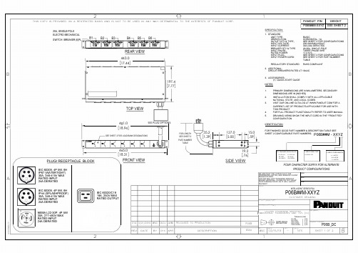
B /l-"' A2 1'rTHIS COPY IS PROVIDED ON A RESTRICTED BASIS AND IS NOT TO BE USED IN ANY WAY DETRIMENTAL TO THE INTERESTS OF PANDUIT CORP.•g •1·,{ 1 I20A, SINGLE-POLEELECTRO MECHANICALSWITCH/ BREAKER (6)PL � 7B27 B37 B47 B57 B671:I•ol1·1·�·11·�·11·�·1! 18 !C:8 !£8 1·�·11·�·11·�·1!�8 !S8 !98REAR VIEW443.0[17.44]•IL 10 197.4[7.77]OJI• •TOP VIEW -lHJ481.0 SEE PLUG OPTIONS[18.94] �/SEE SHEET 2 FOR LOAD BANK DESIGNATIONS�1:=mB1� J I-� I-� 94�I-� I-� I ct> �!!a,! �I465.0I [18.31] IPLUG/RECEPTACLE BLOCK FRONT VIEWIEC 60309, 4P 5W, 6HIP67 (WATERTIGHT)30A, 346-415V MAXRATED INPUT24A DERATEDf3IEC 60309, 4P 5W, 6HIEC 60320/C19IP44 (SPLASHPROOF)30A, 346-415V MAX 16A, 250V MAXRATED INPUT RATED OUTPUT24A DERATEDNEMA L22-30P, 4P 5W30A, 277-480V MAXRATED INPUT24A DERATED01A 3/21/2019 WAC DACU JAWIREV DATE BY CHK APR2T 35.2I127.0 ---j 15.0FOR LENGTH I[1.39] I[5.00]®f-.[.59] ♦SEE SHEET 2PART NUMBERTABLE ]: ® I�19.; J [.76] SIDE VIEWRELEASED TO PRODUCTION P06BDESCRIPTION ECN'(71 IPANDUIT P/N WEIGHTI P06B##M-XXYZ SEE SHEET 2SPECIFICATION:1. STANDARDUNIT TYPE:ORIENTATION:OUTLET QTY & TYPEINPUT VOLTAGE:INPUT CURRENT:BREAKER QTY & TYPE:INPUT PHASE:RATED POWER:INPUT PLUGINPUT POWER CORD:BASICHORIZONTAL, 1USEE SHEET 2 FOR CONFIGURATIONS200-240/346-415VAC30A (24A DERATED)(6) 20A, SINGLE-POLETHREE-PHASE WYE17.3 kVASEE SHEET 2 FOR CONFIGURATIONSSEE SHEET 2FOR PART NUMBERTABLEREGULATORY STANDARD: RoHS COMPLIANT2. ADDITIONALCIRCUIT BREAKERS RATED AT 10kAIC3. ACCESSORIES:(1) QUICK-START GUIDENOTES:1. PRIMARY DIMENSIONS ARE IN MILLIMETERS. SECONDARYDIMENSIONS ARE IN IINCHES]2 .INSTALLATION SHALL COMPLY WITH ALL APPLICABLENATIONAL, STATE, AND LOCAL CODES3.VISIT OUR ON-LINE CATALOG AT FOR ACURRENT LIST OF PRODUCTS APPLICABLE FOR USE WITHTHIS PRODUCT4.FOR FULL PRODUCT FUNCTIONALITY REFER TO USER MANUAL5.DRAWING VIEWS SHOW THE INPUT CORD IN THE "FRONT FED"CONFIGURATIONIDENTIFICATIONFOR FINISHED GOOD PART NUMBER & DESCRIPTION TABLE SEESHEET 2 CONFIGURABLE PART NUMBERS: P06B##M -XXYZIXX: FINISHED GOOD COLORBL=BLACK YL=YELLOWRD=RED BU=BLUEWH =Wl-mE GN =GREENT1I r---Y: INPUT FEED TYPE Z: INPUT CORD LENGTH6=FRONT FEDA=1METERB=2METERC=3METERFOUR CHARACTER SUFFIX FOR AL TE RNA TEPRODUCT CONFIGURATIONSWE ASK THAT YOU CHECK FULLY THE SIGNDIMENSIONS, NOTES, AND SIGNTHE CLIENTSIGNATUTE BOX.THE JOB WILL NOT PROGRESS WITHOUT DATESIGNED APPROVAL. PLEASE DO NOT DELAYIN RETURNING PROOF AS IT WILL AFFECT PRINTDELIVERY.11 I LLINTELLIGENT SERIES POU" " N ''-P06B##M-XXYZCUSTOMER DRAWINGILL N..H RulDUITUNLESS OTHERWISE SPECIFIED,PIMENSIONAL TOLERANCES ARE: mm [IN]Tolerance (mm)D-@ THRIDANGLEPROJECTIONWWAC1I,,I''03/15/19 -O<LS50 I±0.550<LS250 ±1.0250<LS500 ±1.5SOO<L:S:1000 ±2.51000<LS2000 ±4.0I',,NTSw "'"'=-, ,_\!\"r, �-r, ._J f.i 1_r,P06B DCSHEET 1 OF 2 I a�Bh>A(6)C19。

T 07:17:00+02:00型号BI2-EM12-Y1X-H1141货号4010201额定工作距离Sn 2 mm 安装方式齐平实际测量范围ð (0,81 x Sn) mm修正系数37#钢 = 1; 铝 = 0.3; 不锈钢= 0.7; 黄铜 = 0.4重复精度ð 2 满量程的 %温度漂移10 %磁滞1…10 %环境温度-25…+70 °C 输出性能2线, NAMUR 开关频率 5 kHz电压Nom. 8.2 VDC 无激励电流损耗ï 2.1 mA 激励电流损耗ð 1.2 mA认证依据KEMA 02 ATEX 1090X 内置 电感(L ) / 电容 (C )150 nF / 150 µH防爆标志防爆标识为II 1 G/Ex ia IIC T6/II 1 D Ex ia D 20 T115°C Da(最大 U = 20 V, I = 20 mA, P = 200 mW)设计圆柱螺纹, M12 x 1尺寸52 mm外壳材料不锈钢型, V2A (1.4301)感应面材料塑料, PA 最大扭矩10 Nm连接接插件, M12 x 1防震动性55 Hz (1 mm)防冲击性30 g (11 ms)防护等级IP67MTTF 6198 years 符合SN 29500 (Ed.99) 40 °C认证开关状态指示LED指示灯 黄sATEX 防爆认证II 组设备,设备等级1G. 可用于气体危险0区sATEX 防爆认证II组设备,设备等级1D,可应用于粉尘危险2区s 满足SIL2和IEC61508标准s M12 x 1圆柱螺纹s 不锈钢1.4301s 2线直流, nom. 8.2 VDCs输出遵循本安型DIN EN 60947-5-6(NAMUR)标准sM12 x 1接插件接线图功能原理电感式传感器以非接触和无磨损的方式检测金属物体。


no evitarse, provocará la muerte o lesiones graves.Advertencia∙Comprueba siempre la conformidad con las leyes y reglamentos2 Especificaciones (continuación)3 Designación de las piezas3 Designación de las piezas (continuación)4 Instalación4.1 InstalaciónAdvertencia∙Lee detenidamente las normas de seguridad del productoentendiendo su contenido antes de realizar la instalación.∙Utiliza el producto dentro del rango de presión y temperatura detrabajo indicado.∙La presión de prueba podría variar en función de la temperatura delfluido. Comprueba los datos de las características para presión detrabajo y presión de prueba.4.2 EntornoAdvertencia∙Evita utilizar el producto en entornos donde esté expuesto a gasescorrosivos, productos químicos, agua salina o vapor.∙Evita los ambientes explosivos.∙No expongas el producto a la luz directa del sol. Utiliza una cubiertaprotectora adecuada.∙No instales el producto en zonas sometidas a vibraciones o impactossuperiores a los indicados en las características técnicas.∙Evita realizar el montaje del producto en lugares expuestos a calorradiante que provocará un aumento de la temperatura más allá delas características técnicas del producto.∙Consulta la dirección del caudal del fluido indicada en el productopara realizar la instalación y el conexionado.∙No montes el cuerpo con la parte inferior apuntando hacia arriba.La retención de aire puede hacer que no sea posible realizar unamedición precisa.∙No insertes cables metálicos u otros objetos extraños en la conexión.Puede dañar el sensor, provocando fallos o un funcionamiento defectuoso.∙No montes el producto en lugares que se utilizarán como punto de apoyo.El producto puede resultar dañado si se aplica una fuerza excesivasubiéndose encima de él.∙Si existe riesgo de que entren partículas extrañas en el fluido, instalay conecta un filtro o separador de neblina en el lado de entrada paraevitar fallos de funcionamiento.Podrían producirse daños en el producto o fallos de funcionamiento.El código del producto se muestra durante aproximadamente3 segundos tras la activación del suministro eléctrico.Se mostrará el modo de medición y se iniciará el funcionamiento.4.3 Montaje del panel∙ Inserta el adaptador de montaje en panel B (suministrado como accesorio) en la sección A del adaptador de montaje en panel.Empuja el adaptador para montaje en panel B desde la parte trasera hasta que el display quede fijado en el panel.El pasador de la fijación se engancha en la parte ranurada de la sección C del adaptador para panel para fijar el display.∙ El flujostato se puede montar en un panel con un grosor de 1 a 3.2 mm.4.4 Montaje con fijaciones∙ Monta la fijación usando los tornillos de montaje suministrados. ∙ El par de apriete requerido es 0.42 ±0.04 Nm.∙ Instala el producto (con fijación) usando los tornillos M3 (4 uds.) ∙ El grosor de la fijación es aprox. 1.2 mm4.5 ∙ Monta las piezas para montaje en raíl DIN usando los tornillos de montaje y tornillos de unión suministrados.∙ El par de apriete requerido de los tornillos de montaje en raíl DIN y los tornillos de unión es 0.4 ±0.05 Nm.∙ Consulta el manual de funcionamiento en el sitio web de SMC (URL: https:// ) para todas las dimensiones de montaje.4.6 ConexionadoPrecaución∙ Antes de realizar el conexionado, limpia cualquier rastro de virutas, aceite de corte, polvo, etc.∙ Comprueba que no haya fugas después de las tuberías.∙ Elimina el polvo del conexionado usando un soplador de aire antes de conectar el conexionado al producto.Podrían producirse daños en el producto o fallos de funcionamiento.4.7 CableadoPrecaución∙ No conectes ningún cable mientras la corriente esté activada. ∙ Comprueba que el cableado esté correctamente aislado.∙ No coloque los cables en la misma trayectoria que una línea de potencia o de alta tensión.En caso contrario, el producto puede sufrir un funcionamiento defectuoso debido a las interferencias por ruido y a los picos de tensión desde los cables de potencia y alta tensión hacia la línea de señal. ∙ El cableado debe ser tan corto como sea posible para evitar interferencias de ruido electromagnético y picos de tensión. No uses un cable con longitud superior a 30 m.∙ Asegúrate de que el terminal FG está conectado a tierra cuando utilices un regulador de conmutación comercial.∙ Si se usa la salida analógica, instala un filtro de ruido (filtro de línea, núcleo de ferrita, etc.) entre el suministro de alimentación para conmutación y este producto.Conexión/Desconexión∙ Cuando montes el conector, introdúcelo recto en el enchufe sujetando la palanca y el cuerpo del conector y empuja el conector hasta que la palanca enganche firmemente en la carcasa para bloquearlo.∙ Para desmontar el conector, presiona la palanca hacia abajo para soltar el gancho de la carcasa y extraiga el conector.Numeración de pins del conector (en el cable)Se suministra alimentación*: Las salidas continuarán funcionando durante el ajuste.*: Los ajustes del modo de ajuste sencillo y el modo de selección de función se reflejan unos en otros.6 Ajuste del caudal6.1 Operación de conmutaciónCuando el caudal exceda el punto de disparo, la salida del flujostato se activará. Cuando el caudal caiga por debajo del punto de disparo en la cantidad de histéresis o más, la salida se apagará.El valor de ajuste por defecto es el valor para activar el flujostato cuando el caudal está en el punto medio entre el límite inferior y el límite superior del rango de caudal nominal.Si esta condición mostrada resulta aceptable, mantén estos ajustes. *: Para la histéresis, consulta [F 1] Ajuste de OUT1 y [F 2] Ajuste de OUT2.[Modo de ajuste sencillo (modo de histéresis)]El modo de ajuste sencillo, el valor de ajuste y la histéresis se pueden modificar.(1) Pulsa el botón SET una vez en el modo de medición.Se mostrarán alternativamente [P_1] o [n_1] y el valor de ajuste de corriente.(2) Cambia el valor de ajuste usando el botón UP o DOWN y pulsa el botón SET para ajustar el valor. A continuación, el ajuste se mueve al ajuste de la histéresis (se puede usar la función instantánea). ∙ Mantén pulsado el botón UP para aumentar rápidamente el valor de ajuste.∙ Mantén pulsado el botón DOWN para disminuir rápidamente el valor de ajuste.(3) [H_1] y el valor de ajuste actual aparecerán alternativamente en el display.(4) Cambia el o DOWN ypulsa el botón SET. El ajuste se completa y el producto vuelve al modo de medición (Se puede usar la función instantánea).* En los modelos 2 salidas digitales para OUT1 y para OUT2, se mostrará [P_2] o [n_2]. Se ajustan simultáneamente.* Tras habilitar el ajuste pulsando el botón SET, es posible volver al modo de medición pulsando el botón SET durante al menos 2 segundos.* Si no se usa el modo de histéresis, se muestra «Valor de ajuste de entrada».* El valor de ajuste y la histéresis se limitan entre sí.* Para más detalles sobre los ajustes, vuelva a poner todas las funciones en el modo de selección de función.8 Ajuste de función8.1 Modo de selección de funciónEn el modo de medición, pulsa el botón SET durante 2 a 5 segundos para visualizar [F 0] en el display.Selecciona la función que se vaya a cambiar [F ].Pulsa el botón SET durante al menos 2 segundos en el modo de selección de función para volver al modo de medición. *: Algunos productos no disponen de todas las funciones. Si no hay ninguna función disponible o seleccionada debido a la configuración de otras funciones, se muestra [- - -] en el display secundario.Sin válvula de regulación de caudal (usando ZS-33-M) Con válvula de regulación de caudal (usando ZS-33-MS) C a u d a l8.2 Ajustes por defecto* El ajuste [Unidades] sólo es posible para modelos con función de selección de unidades.* La función [F 2] sólo está disponible para modelos con salidas digitales OUT1 y OUT2.* La función [F22] solo está disponible para modelos con salida analógica. Se puede seleccionar la función de intervalo analógico libre. ∙Función instantánea∙Función de bloqueo del teclado∙Función de puesta a ceroConsulta el manual de funcionamiento en el sitio web de SMC (URL:https://)10 Mantenimiento10.1 Mantenimiento generalPrecaución∙El incumplimiento de los procedimientos de mantenimientoapropiados podría causar un funcionamiento defectuoso delproducto, produciendo daños al equipo.∙El aire comprimido puede resultar peligroso si se maneja de manerainadecuada.∙El mantenimiento de los sistemas neumáticos debe realizarseúnicamente por personal cualificado.∙Antes de llevar a cabo el mantenimiento, corta el suministro eléctricoy la presión de alimentación. Comprueba que el aire se hadescargado a la atmósfera.∙Tras la instalación y el mantenimiento, conecta el suministro eléctricoy de presión al equipo y realiza pruebas de funcionamiento y defugas para comprobar que el equipo está correctamente instalado.∙Si alguna conexión eléctrica resulta afecta durante el mantenimiento,asegúrate de que vuelvan a conectarse correctamente y que se llevana cabo las comprobaciones de seguridad necesarias para garantizar laconformidad continuada con la reglamentación nacional aplicable.∙No realices ninguna modificación del producto.∙No desmontes el producto a menos que se indique en lasinstrucciones de instalación o mantenimiento.∙Cómo reiniciar el producto tras un corte de alimentación ocuando la alimentación se ha desconectado inesperadamenteSe mantendrán los ajustes existentes antes del corte de alimentacióno de la desactivación.También se recuperará el estado de salida existente antes del cortede alimentación o de la desactivación, aunque puede variar enfunción del entorno de trabajo.Por tanto, comprueba la seguridad de toda la instalación antes deutilizar de nuevo el producto.11 Forma de pedidoConsulta el catálogo/diagramas para la «Forma de pedido».12 Dimensiones externas (mm)Consulta las dimensiones externas el manual de funcionamiento en elsitio web de SMC (URL: ) .13.1 Indicación de errorSi el error no puede solucionarse después de tomar las medidasindicadas, o si se muestran errores distintos a los anteriores, ponte encontacto con SMC.Consulta el manual de funcionamiento en el sitio web de SMC (URL:https://) para obtener información detallada sobre laresolución de problemas.14.1 Garantía limitada y exención de responsabilidades/Requisitosde conformidadConsulta las «Precauciones en el manejo de productos SMC».15 ContactosConsulta la Declaración de Conformidad y URL: https://para los contactos.URL: (Global) http// (Europa)SMC Corporation, Akihabara UDX15F, 4-14-1, Sotokanda, Chiyoda-ku, Tokio 1010021 JAPÓNLas especificaciones pueden sufrir modificaciones sin previo aviso por parte delfabricante.© 2019 SMC Corporation Todos los derechos reservados.Plantilla DKP50047-F-085H。

C i r c u i t b r e a k e r sCircuit breakersTeSys GV, GBC ontrol and P rotection C omponentsChapterB60.75g g 1.1g g 1.5375 2.533.5 LR2 K0308GV2LE071.1g g –––––– 2.533.5 LR2 K0308GV2LE071.5g g 1.5g g 3375451 LR2 K0310GV2LE08––– 2.2g g –––451 LR2 K0312GV2LE082.2g g 3501004375 6.378 LR2 K0312GV2LE103g g 410100 5.537510138 LR2 K0314GV2LE144g g 5.510100–––10138 LR2 K0316GV2LE14––––––7.537510138 LRD 14GV2LE14––––––937514170 LRD 16GV2LE165.515507.56751137514170 LR2 K0321GV2LE167.5155096751537518223 LRD 21GV2LE20915401147518.537525327 LRD 22GV2LE2211154015475–––25327 LRD 22GV2LE2215105018.54752237532416LRD 32GV2LE32(1) As % of Icu.g ) > 100 kA.GV2 LE10D F 526144.t i fC i r c u i t b r e a k e r s0.09––––––0.45LRD 03GV2L030.12g g –––0.37g g 0.638LRD 04GV2L040.18g g ––––––0.638LRD 04GV2L04––––––0.55g g 113LRD 05GV2L050.25g g ––––––113LRD 05GV2L05––––––0.75g g 113LRD 06GV2L050.37g g 0.37g g –––113LRD 05GV2L050.55g g 0.55g g 1.1g g 1.622.5LRD 06GV2L06–––0.75g g ––– 1.622.5LRD 06GV2L060.75g g 1.1g g 1.54100 2.533.5LRD 07GV2L07Example: GV3 L32 becomes GV3 L326.(1) As % of Icu. Associated current limiter or fuses, where required. See characteristics page B6/33.g > 100 kA.GV2 L10D F 526145.t i fGV3 L65D F 526146.t i fTeSys GVThermal-magnetic motor circuit breakers GV2 ME0.06gg––––––0.16…0.252.4GV2ME020.09g g––––––0.25…0.405GV2ME030.12 0.18g g g g – –– –– – 0.37 –g–g –0.40…0.638GV2ME040.25gg––– 0.55gg0.63…113GV2ME050.37 0.55 –g g –g g –0.37 0.55 0.75g g g g g g – 0.75 1.1– g g – g g 1…1622.5GV2ME060.75g g1.1gg1.5375 1.6...2.533.5GV2ME071.1 1.5g g g g 1.5 2.2g g g g 2.2 3 3 375 75 2.5 (4)51GV2ME082.2gg350100 43754...6.378GV2ME103 4g g g g 4 5.510 10100 100 5.5 7.5 3 375 756 (10)138GV2ME145.5 –15 –50 –7.5 – 6 –75 – 9 11 3 375 759…14170GV2ME167.5155096751537513…18223GV2ME209154011475 18.537517…23327GV2ME2111154015475 –––20…25327GV2ME22 (3)15105018.54752237524 (32)416GV2ME32Motor circuit breakers from 0.06 to 15 kW / 400 V, with lugsTo order thermal magnetic circuit breakers with connection by lugs, add the digit 6 to the end of reference selected above.Example: GV2 ME08 becomes GV2 ME086.Thermal magnetic circuit breakers GV2 ME with built-in auxiliary contact block With instantaneous auxiliary contact block (composition, see page B6/11):b GV AE1, add suffix AE1TQ to the motor circuit breaker reference selected above. Example: GV2 ME01AE1TQ .b GV AE11, add suffix AE11TQ to the motor circuit breaker reference selected above. Example: GV2 ME01AE11TQ .b GV AN11, add suffix AN11TQ to the motor circuit breaker reference selected above. Example: GV2 ME01AN11TQ .These circuit breakers with built-in contact block are sold in lots of 20 units in a single pack.(1) As % of Icu.(2) The thermal trip setting must be within the range marked on the graduated knob.(3) Maximum rating which can be mounted in enclosures GV2 MC or MP , please consult your Regional Sales Office. g > 100 kA.GV2 ME10D F 526134.t i fC i r c u i t b r e a k e r sTeSys GVTeSys protection componentsThermal-magnetic motor circuit breakers GV2 MEReferences0.06g g ––– 0.16…0.25 2.4GV2ME0230.09g g ––– 0.25…0.405GV2ME0330.120.18g g g g –––0.40…0.638GV2ME0430.250.37g g g g 0.37g g 0.63…113GV2ME0530.370.55g g g g 0.370.550.75g g g g g g 1…1.622.5GV2ME0630.75g g1.1g g 1.6…2.533.5GV2ME0731.11.5g g g g 1.52.2g g g g 2.5…451GV2ME0832.2g g 350100 4…6.378GV2ME10334g g g g 45.510101001006…10138GV2ME1435.515507.5675 9…14170GV2ME1637.515509675 13…18223GV2ME203911151540401147517…23327GV2ME2131115401547520 (25)327GV2ME223Contact blocksDescription Mounting Maximum number Type of contacts Sold in lots of Unitreference Instantaneous auxiliary contactsFront 1N/O + N/C 10GVAE113N/O + N/O 10GVAE203LH side2N/O + N/C 1GVAN113N/O + N/O1GVAN203AccessoryDescriptionApplicationSold in lots of Unitreference Cable end reducerFor connection of conductors from 1 to 1.5 mm 220LA9D99(1) For connection of conductors from 1 to 1.5 mm 2, the use of an LA9 D99 cable end reducer is recommended.(2) Maximum rating which can be mounted in enclosures GV2 MC or MP , please consult your Regional Sales Office (3) The thermal trip setting must be within the range marked on the graduated knob.g > 100 kA.GV2 ME pp 3D F 526135.t i fLA9 D99D F 533898.e p sTeSys GVReferencesTeSys protection componentsThermal-magnetic motor circuit breakersGV2 P, GV3 P and GV3 ME80GV2 P10D F 526137.t i fGV3 P65D F 526139.t i fGV3 P651D F 526140.t i fC i r c u i t b r e a k e r sTeSys GVReferences93610011181001581007.59707010010091150501001001115101010010012…20GV7RS20 2.0109113636100100111518181001001518.58810010015…25GV7RE25 2.0109117070100100111550501001001518.5101010010015…25GV7RS25 2.01018.53610018.522181810010022810025…40GV7RE40 2.01018.57010018.550100221010025…40GV7RS40 2.0102236100301810030810030…50GV7RE50 2.01522701003050100301010030 (50)GV7RS502.01537361004555181810010055810048...80GV7RE80 2.040377010045555050100100551010048...80GV7RS80 2.0404536100–1810075810060...100GV7RE100 2.0404570100–50100751010060...100GV7RS100 2.0405575353510010075903030100100901108810010090 (150)GV7RE1502.020557570701001007590505010010090110101010010090…150GV7RS150 2.02090110353510010011013216030303010010010016020088100100132…220GV7RE220 2.3509011070701001001101321605050501001001001602001010100100132…220GV7RS220 2.350(1) As % of lcu.TeSys protection componentsThermal-magnetic motor circuit breakers GV7 RGV7 RE40D F 526138.t i fGV7 RS220D F 526141.t i f0.12–0.120.180.18–0.370.40…0.6313GV2RT040.090.120.250.370.250.370.370.550.63…122GV2RT050.180.250.370.550.370.550.370.550.750.751.11…1.633GV2RT060.370.750.751.1 1.11.51.6…2.551GV2RT070.550.75 1.11.5 1.51.52.2 2.23 2.5…478GV2RT081.12.22.23344…6.3138GV2RT101.52.234445.5 5.57.56…10200GV2RT142.23 5.55.57.57.59119…14280GV2RT1647.57.5991513…18400GV2RT205.5911111118.517…23400GV2RT21(1) The thermal trip setting must be within the range marked on the graduated knob.GV2 RTD F 526142.t i fC i r c u i t b r e a k e r sblack handle, blue legend plate(1) The thermal trip setting must be within the range marked on the graduated knob.(2) Other accessories such as mounting, cabling and marking accessories are identical to those used for GV2 ME motor circuit breakers, see page B6/13.GV2 RTD F 526142.t i fD F 526340.e p sC i r c u i t b r e a k e r sTeSys GVDescription Mounting Maximum number Type of contacts Sold inlots of Unitreference Instantaneous auxiliary contactsFront (1)1N/O or N/C (2)10GVAE1N/O + N/C 10GVAE11N/O + N/O10GVAE20Side (LH)2N/O + N/C1GVAN11N/O + N/O1GVAN20Fault signalling contact + instantaneous auxiliary contact Side (3) (LH)1N/O (fault)+ N/O1GVAD1010+ N/C1GVAD1001N/C (fault)+ N/O1GVAD0110+ N/C1GVAD0101Short-circuit signalling contactSide (LH)1C/O common point1GVAM11(1 block on RH sideof circuit breaker GV2 ME)50 Hz GVAX11560 Hz GVAX116127 V60 Hz GVAX115220…240 V 50 Hz GVAX22560 Hz GVAX226380…400 V50 Hz GVAX38560 Hz GVAX386415…440 V 50 Hz GVAX415440 V60 Hz GVAX385Add-on contact blocksDescriptionMountingMaximum number Reference Visible isolation block (5)Front (1)1GV2AK00 (6)LimitersAt top(GV2 ME and GV2 P)1GV1L3Independent1LA9LB920(1) Mounting of a GV AE contact block or a GV2 AK00 visible isolation block on GV2 P and GV2 L .(2) Choice of N/C or N/O contact operation, depending on which way round the reversible block is mounted.(3) The GV AD is always mounted next to the circuit breaker.(4) To order an undervoltage trip: replace the dot (p ) in the reference with a U , example: GV AU025. To order a shunt trip: replace the dot (p ) in the reference with an S , example: GV AS025.(5) Visible isolation of the 3 poles upstream of circuit breaker GV2 P and GV2 L .Visible isolation block GV2 AK00 cannot be used with motor circuit breakers GV2 P32 and GV2 L32 (Ith max = 25 A).(6) Ie Max = 32 A.ReferencesTeSys protection componentsThermal-magnetic and magnetic motor circuit breakers GV2 with screw clamp connectionsAdd-on blocks and accessoriesCharacteristics:pages B6/89 and B6/94Dimensions, schemes:pages B6/70 to B6/82LA9LB920D B 126629.e p sC i r c u i t b r e a k e r sTeSys GVTerminal blockfor supply to one or more GV2 G busbar setsConnection from the top1GV1G09Can be fitted with current limiter GV1 L3 (GV2 ME and GV2 P)1GV2G05Cover for terminal block For mounting in modular panels10LA9E07Flexible 3-pole connection for connecting a GV2 to a contactor LC1-D09…D25 Centre distance between mounting rails: 100…120 mm10GV1G02Set of connections upstream/downstream For connecting GV2 ME to a printed circuit board 10GV2GA01“Large Spacing” adapter UL 508 type EFor GV2 P pp H7 (except 32 A)1GV2GH7Clip-in marker holders (supplied with each circuit breaker)For GV2 P , GV2 L, GV2 LE and GV2 RT (8 x 22 mm)100LA9D92ReferencesTeSys protection componentsThermal-magnetic and magnetic motor circuit breakers GV2 with screw clamp connectionsAccessoriesDimensions, schemes:pages B6/70 to B6/82D B 417942.e p sTeSys GVD B 126631.e p sD B 126630.e p sD B 126632.e p s7P B 106297_45.e p sExtended Rotary HandleAllows a circuit breaker or a starter-controller installed in back of an enclosure to be operated from the front of the enclosure.A rotary handle can be black or red/yellow, IP54 or IP65. It includes a function for locking the circuit breaker or the starter in the O (Off) or I (On) position(depending of the type of rotary handle) by means of up to 3 padlocks with a shank diameter of 4 to 8 mm. The extended shaft must be adjusted to use in different size enclosures. The IP54 rotary handle is fixed with a nut (Ø22) to make easierthe assembling. The new Laser Square tool brings the accuracy to align the circuit breaker and the rotary handle.device(padlocks not included)ReferencesTeSys protection componentsThermal-magnetic and magnetic motor circuit breakers GV2 with screw clamp connectionsC i r c u i t b r e a k e r sTeSys GVDescriptionMounting Maximum number Type of contacts Sold inlots of Unitreference Instantaneous auxiliary contactsFront1N/O or N/C (1)10GVAE1N/O + N/C 10GVAE11 (2)N/O + N/O10GVAE20 (2)Side (LH)2N/O + N/C1GVAN11 (2)N/O + N/O1GVAN20 (2)Fault signalling contact + instantaneous auxiliary contactFront 1N/O (fault)+ N/O1GVAED101 (2)N/O (fault)+ N/C1GVAED011 (2)Side (3) (LH)1N/O (fault)+ N/O1GVAD1010+ N/C1GVAD1001N/C (fault)+ N/O1GVAD0110+ N/C1GVAD0101Short-circuit signalling contact Side (LH)1C/O common point 1GVAM11(4)MountingVoltage ReferenceSide(1 block on RH side of circuit breaker)24 V 50 Hz GVA p 02560 Hz GVA p 02648 V 50 Hz GVA p 05560 Hz GVA p 05610050 Hz GVA p 107100…110 V 60 Hz GVA p 107110…115 V 50 Hz GVA p 11560 Hz GVA p 116120…127 V 50 Hz GVA p 125127 V 60 Hz GVA p 115200 V50 Hz GVA p 207200…220 V 60 Hz GVA p 207220…240 V 50 Hz GVA p 22560 Hz GVA p 226380…400 V 50 Hz GVA p 38560 Hz GVA p 386415…440 V 50 Hz GVA p 415415 V 60 Hz GVA p 416440 V 60 Hz GVA p 385480 V 60 Hz GVA p 415500 V 50 Hz GVA p 505600 V60 HzGVA p 505AccessoriesDescription Reference Sets of 3-pole 115 A busbars Pitch: 64 mm2 tap-off GV3 P pp and GV3 L pp GV3G2643 tap-off GV3 P pp and GV3 L pp GV3G364Cover “Large Spacing” UL 508 type E (Only one cover required on supply side)GV3 P ppGV3G66(1) Choice of N/C or N/O contact operation, depending on which way round the reversible block is mounted.(2) Contact blocks available in version with spring terminal connections. Add a figure 3 at the end of the references selected above. Example: GV AED101 becomes GV AED1013.(3) The GV AD pp is always mounted next to the circuit breaker.(4) To order an undervoltage trip: replace the dot (p ) in the reference with a U , example: GV AU025. To order a shunt trip: replace the dot (p ) in the reference with an S , example: GV AS025.Add-on blocks and accessoriesGV3 G66D F 537424.e p sTeSys GVD B 126637.e p sD B 126636.e p sD B 126632.e p s7P B 106297_45.e p sExtended Rotary HandleAllows a circuit breaker or a starter-controller installed in back of an enclosure to be operated from the front of the enclosure.A rotary handle can be black or red/yellow, IP54 or IP65. It includes a function for locking the circuit breaker or the starter in the O (Off) or I (On) position(depending of the type of rotary handle) by means of up to 3 padlocks with a shank diameter of 4 to 8 mm. The extended shaft must be adjusted to use in different size enclosures. The IP54 rotary handle is fixed with a nut (Ø22) to make easierthe assembling. The new Laser Square tool brings the accurency to align the circuit breaker and the rotary handle.For English 10-GVAPSEN For German 10-GVAPSDE For Spanish10-GVAPSES For Chinese 10-GVAPSCN For Portuguese 10-GVAPSPT For Russian 10-GVAPSRU For Italian10-GVAPSITD F 526342.e p sB6/21C i r c u i t b r e a k e r sTeSys GVfor locking the Start button (on open-mounted product)using up to 3 padlocks(padlocks to be ordered separately)External operator for mounting on enclosure door.Red Ø40 knob on yellow plate, padlockable in position O (with up to 3 padlocks). Door locked when knob in position I, and when knob padlocked in position O.GK3AP03(1) 1 voltage trip OR 1 fault signalling contact to be fitted inside the motor circuit breaker.Other versions24 to 690 V, 50 or 60 Hz voltage trips for circuit breakers GV3 ME80.Please consult your Regional Sales Office.ReferencesTeSys protection componentsMotor circuit breakers GV3 ME80 and GK3 EF80Add-on blocks and accessoriesCharacteristics:pages B6/89 and B6/92Dimensions:page B6/47B6/22D F 526344.e p sB6/23C i r c u i t b r e a k e r sTeSys GVThese allow remote indication of the circuit breaker contact states. They can be used for signalling, electrical locking, relaying, etc. They are available in two versions: standard and low level. They include a terminal block and the auxiliary circuits leave the circuit breaker through a hole provided for this purpose.They perform the following functions, depending on where they are located in the circuit breaker:Low levelGV7AB11Fault discrimination devicesThese make it possible to:b either differentiate a thermal fault from a magnetic fault,b or open the contactor only in the event of a thermal fault.VoltageReference a 24...48 and c 24…72 V GV7AD111 (1)z 110…240 VGV7AD112 (1)Electric tripsThese allow the circuit breaker to be tripped via an electrical control signal.b Undervoltage trip GV7 AUv Trips the circuit breaker when the control voltage drops below the tripping threshold, which is between 0.35 and 0.7 times the rated voltage.v Circuit breaker closing is only possible if the voltage exceeds 0.85 times the rated voltage. Circuit breaker tripping by a GV7 AU trip meets the requirements of IEC 60947-2.b Shunt trip GV7 ASTrips the circuit breaker when the control voltage rises above 0.7 times the rated voltage.b Operation (GV7 AU or GV7 AS)v When the circuit breaker has been tripped by a GV7 AU or AS, it must be reset either locally or by remote control. (For remote control, please consult your Regional Sales Office).v Tripping has priority over manual closing: if a tripping instruction is present, manual action does not result in closing, even temporarily, of the contacts.v Durability: 50 % of the mechanical durability of the circuit breaker.TypeVoltageReference Undervoltage trip48 V, 50/60 HzGV7AU055 (1)110…130 V, 50/60 Hz GV7AU107 (1)200…240 V, 50/60 Hz GV7AU207 (1)380…440 V, 50/60 Hz GV7AU387 (1)525 V, 50 HzGV7AU525 (1)Shunt trip48 V, 50/60 HzGV7AS055 (1)110…130 V, 50/60 Hz GV7AS107 (1)200…240 V, 50/60 Hz GV7AS207 (1)380…440 V, 50/60 Hz GV7AS387 (1)525 V, 50 HzGV7AS525 (1)(1) For mounting of a GV7 AD or a GV7 AU or AS.ReferencesTeSys protection componentsThermal-magnetic motor circuit breakers GV7 R with screw clamp connectionsAdd-on blocks and accessoriesCharacteristics:pages B6/51, B6/52 and B6/56Dimensions:pages B6/79 to B6/81Schemes:page B6/83B6/24B6/25C i r c u i t b r e a k e r sTeSys GVDescription ApplicationFor use on contactors Sold in lots of Unitreference Clip-on connectors for GV7 RUp to 150 A, 1.5…95 mm 2–3GV7AC021Up to 220 A, 1.5…185 mm 2–3GV7AC022Spreader 3-pole (1)To increase the pitch to 45 mm–1GV7AC03Terminal shields IP 405 (1)Supplied with sealing accessory–1GV7AC01Phase barriersSafety accessories used when fitting of shields is impossible –2GV7AC04Insulating screens Ensure insulation between the connections and the backplate –2GV7AC05Kits for combination with contactor (2)Allowing link between thecircuit breaker and the contactor. The cover provides protection against direct finger contactLC1 F115…F1851GV7AC06LC1 F225 and F2651GV7AC07LC1 D115 and D1501GV7AC08Replaces the circuit breaker front cover; secured by screws. It includes a device for locking the circuit breaker in the O (Off) position by means of up to 3 padlocks with a shank diameter of 5 to 8 mm (padlocks not included). A conversion accessory allows the direct rotary handle to be mounted on the enclosure door. In this case, the door cannot be opened if the circuit breaker is in the “ON” position. Circuit breaker closing is inhibited if the enclosure door is open.Description TypeDegree of protection Reference Direct rotary handleBlack handle, black legend plate IP 40GV7AP03Red handle, yellow legend plateIP 40GV7AP04Adapter plate (3)Four mounting direct rotary handle on enclosure doorIP 43GV7AP05Allows a circuit breaker installed in the back of an enclosure to be operated from the front of the enclosure. It comprises:b a unit which screws onto the front cover of the circuit breaker,b an assembly (handle and front plate) to be fitted on the enclosure door,b an extension shaft which must be adjusted (distance between the mounting surface and the door: 185 mm minimum, 600 mm maximum). It includes a device for locking the circuit breaker in the O (Off) position by means of up to 3 padlocks with a shank diameter of 5 to 8 mm (padlocks not included). This prevents the enclosure door from being opened.DescriptionTypeDegree of protection Reference Extended rotary handleBlack handle, black legend plate IP 55GV7AP01Red handle, yellow legend plateIP 55GV7AP02Allows circuit breakers not fitted with a rotary handle to be locked in the O (Off) position by means of up to 3 padlocks with a shank diameter of 5 to 8 mm (padlocks not included).Description ApplicationReference Locking deviceFor circuit breaker not fitted with a rotary handleGV7V01(1) Terminal shields cannot be used together with spreaders.(2) The kit comprises links, a protective shield and a depth adjustable metal bracket for the breaker.(3) This conversion accessory makes it impossible to open the door if the device is closed and prevents the device from being closed if the door is open.ReferencesTeSys protection componentsThermal-magnetic motor circuit breakers GV7 R with screw clamp connectionsAccessoriesGV7 AC07D F 537429.e p sGV7 AC08D F 537428.e p sDimensions:pages B6/79 to B6/81B6/260.5 6.63GB2DB051143GB2DB062263GB2DB073403GB2DB084503GB2DB095663GB2DB106833GB2DB1281083GB2DB14101383GB2DB16121653GB2DB20162203GB2DB21202703GB2DB22(1) Conforming to IEC 60947-1.GB2 CBppD F 526243.t i fGB2 CD ppD F 526244.t i fGB2 DBppD F 526245.t i fPresentation, selection :page B6/84Characteristics :pages B6/85 to B6/87Dimensions :page B6/88Schemes :page B6/88B6/27C i r c u i t b r e a k e r s(1) Conforming to IEC 60947-1.Accessories for circuit breakers GB2-CB, DB and CSDescriptionSold in lots of Unitreference Busbar set for supply to 10 GB2 DB or20 GB2 CB or GB2 CS with 2 connectors1GB2G210Supply connector 10GB2G01GB2 CS ppD F 526246.t i fPresentation, selection :page B6/84Characteristics :pages B6/85 to B6/87Dimensions :page B6/88Schemes :page B6/88B6/28B6/29B6/30TeSys GVCharacteristicsTeSys protection componentsMagnetic motor circuit breakers GV2 LE and GV2 LReferences:pages B6/2 and B6/3Dimensions:pages B6/43 to B6/47Schemes:page B6/48add-on contact blocks. Side by side mounting is possible up to 40 °C.(2) When mounting on a vertical rail, fit a stop to prevent any slippage.(1) As % of Icu.Average operating times at 20 °C related to multiples of the setting currentD F 534092.e p s1 3 poles from cold state2 2 poles from cold state3 3 poles from hot stateDynamic stressI peak = f (prospective Isc) at 1.05 Ue = 435 VD F 534093.e p s1 Maximum peak current2 32 A3 25 A4 18 A5 14 A6 10 A7 6.3 A8 4 A9 2.5 A 10 1.6 A11 Limit of rated ultimate breaking capacity on short-circuit of GV2 LE (14, 18, 23 and 25 A ratings).Dynamic stressI peak = f (prospective Isc) at 1.05 Ue = 435 VD F 534094.e p s1 Maximum peak current2 32 A3 25 A4 18 A5 14 A6 10 A7 6.3 A8 4 A9 2.5 A 10 1.6 A11 Limit of rated ultimate breaking capacity on short-circuit of GV2 LE (14, 18, 23 and 25 A ratings).Thermal limit in kA 2s in the magnetic operating zone Sum of I 2dt = f (prospective Isc) at 1.05 Ue = 435 V22Prospective Isc (kA)D F 534095.e p s1 32 A 2 25 A3 18 A4 14 A5 10 A6 6.3 A7 4 A8 2.5 A9 1.6 AThermal limit in kA 2s in the magnetic operating zone Sum of I 2dt = f (prospective Isc) at 1.05 Ue = 435 V22D F 534096.e p s1 25 A and 32 A 2 18 A3 14 A 4 10 A5 6.3 A6 4 A7 2.5 A8 1.6 AThermal limit in kA 2s in the magnetic operating zone Sum of I 2dt = f (prospective Isc) at 1.05 Ue = 435 V22D F 534097.e p s1 32 A (GV2 LE32)2 25 A and 32 A (GV2 L32)3 18 A4 14 A5 10 A6 6.3 A7 4 A8 2.5 A9 1.6 A10 Limit of rated ultimate breaking capacity on short-circuit of GV2 LE (14, 18, 23 and 25 A ratings).Average operating time at 20 °C without prior current flowx the setting current (Ir)D F 534098.e p s1 3 poles from cold state2 2 poles from cold state3 3 poles from hot stateA Thermal overload relay protection zoneB GV3 L protection zoneDynamic stressI peak = f (prospective Isc) at 1.05 Ue = 435 VProspective Isc (kA)D B 418280.e p s1 Maximum peak current2 GV3 L653 GV3 L504 GV3 L405 GV3 L326 GV3 L25Thermal limit in A 2sSum of I 2dt = f (prospective Isc) at 1.05 Ue = 435 V2Prospective Isc (kA)D B 418279.e p s1 GV3 L652 GV3 L503 GV3 L404 GV3 L325 GV3 L25TeSys GVDimensions, mountingD F 537440.e p sD F 537441.e p sD F 537444.e p sTeSys protection componentsMagnetic motor circuit breakers GV2 L and GV2 LETeSys GVDimensions, mounting TeSys protection componentsMagnetic motor circuit breakers GV2 L and GV2 LED B 127415.e p sD B 127414.e p sa b Mini Maxi Mini Maxi GV2 APN pp140250GV2 APN pp + GV APH02151250GV2 APN pp + GV APK11250434--GV2 APN pp + GV APH02 + GV APK11--250445TeSys GVDimensions,mounting Sets of busbars GV2 G445, GV2 G454, GV2 G472, with terminal block GV2 G05D F 537451.e p sGV2 G445224269314359GV2 G454260314368422GV2 G472332404476548D F 537452.e p sD F 537454.e p sGV2 G345 (3 x 45 mm)134GV2 G354 (3 x 54 mm)152TeSys protection componentsMagnetic motor circuit breakers GV2 L and GV2 LED F 537480.e psD F 537435.e p sD F 510637.e p sD F 510638.e p sD B 127416.e p sD B 127417.e p sa b Mini Maxi Mini Maxi GV3 APN pp189300--GV3 APN pp + GV APK12300481GV3 APN pp + GV APH03--200300GV3 APN pp + GV APH03 + GV APK12--300492TeSys GVSchemesTeSys protection componentsMagnetic motor circuit breakers GV2 L, GV2 LE, GV3 LD F 537474.e p sD F 537475.e p sD F 537476.e p sGV2 ME, GV2 P , GV3 ME, GV3 P and GV7 R motor circuit breakers are 3-pole thermal-magnetic circuit breakers specifically designed for the control and protection of motors , conforming to standards IEC 60947-2 and IEC 60947-4-1.Connection GV2GV2 ME and GV2 P circuit breakers are designed for connection by screw clamp terminals.Circuit breaker GV2 ME can be supplied with lugs or spring terminal connections.Spring terminal connections ensure secure, permanent and durable clamping that is resistant to harsh environments, vibration and impact and are even more effective when conductors without cable ends are used. Each connection can take two independent conductors.GV3GV3 circuit breakers feature connection by BTR screws (hexagon socket head), tightened using a n° 4 Allen key.This type of connection uses the Ever Link ® system with creep compensation (1) (Schneider Electric patent).This technique makes it possible to achieve accurate and durable tightening torque, in order to avoid cable creep.GV3 circuit breakers are also available with connection by lugs. This type of connection meets the requirements of certain Asian markets and is suitable for applications subject to strong vibration, such as railway transport.GV7GV7 circuit breakers: with connection by screw clamp terminals (for bars and lugs) and by clip-on connectors.OperationControl is manual and local when the motor circuit breaker is used on its own.Control is automatic and remote when it is associated with a contactor.GV2 ME and GV3 ME80Pushbutton control.Energisation is controlled manually by operating the Start button “I” 1.De-energisation is controlled manually by operating the Stop button “O” 2, or automatically by the thermal-magnetic protection elements or by a voltage trip attachment.GV2 P , GV3 P and GV7 Rb Control by rotary knob: for GV2 P and GV3 P b Control by rocker lever: for GV7 R.Energisation is controlled manually by moving the knob or rocker lever to position “I” 1.De-energisation is controlled manually by moving the knob or rocker lever to position “O” 2.De-energisation due to a fault automatically places the knob or rocker lever in the “Trip” position 3.Re-energisation is possible only after having returned the knob or rocker lever to position “O”.(1) Creep: normal crushing phenomenon of copper conductors, that is accentuated over time.GV2 MEwith screw clamp terminals124D F 526134.t i fGV2 MEwith spring terminals connections124D F 526135.t i fGV3 P1324D F 526136.t ifGV2 P1342D F 526137.t i fGV7 R132D F 526138.t i f。
Schneider Baoguang关于施耐德宝光施耐德(陕西)宝光电器有限公司(简称SSBEA或施耐德宝光)是施耐德电气专业从事中、系统及相关产品研发、生产和销售的中外合资企业。
高新科技园区。
在世界五百强企业与中国中压电器龙头企业的通力合作下,作为国内中压行业著名的“宝光”品牌真空断路器的唯一合法生产商,施耐德宝光秉承精益生产科学理念,凭借品质过硬、安全可靠的全系列高品质产品和覆盖用户全生命周期的完善服务,帮助用户实现卓越的生产运营绩效和市场竞争力,用品质的“不妥协”实现可持续发展之道。
我们致力于将施耐德宝光打造成为中国卓越和高效的中压断路器和系统的制造平台,依托自身的专业优势,为广大用户和合作伙伴提供领先的总成本和长期全面的安心保障。
目 录概述VS1 Pro-12X 型户内高压真空断路器(以下简称断路器)是额定电压12kV 及以下、交流50Hz 的户内开关设备元件。
断路器与KYN28A-12型开关柜配套使用,也可安装于XGN2等固定式开关柜内。
产品符合GB 1984《高压交流断路器》、GB/T 11022 《高压开关设备和控制设备标准的共用技术要求》、JB/T 3855《高压交流真空断路器》、DL/T 403《12kV~40.5kV 高压真空断路器订货技术条件》等标准的规定。
断路器采用弹簧操动机构,可以用交、直流电源储能,也可用手动储能。
具有体积小、开断能力强、绝缘强度高、无污染、无爆炸危险等优点。
产品无论在配电系统正常条件下还是故障条件下(特别是在短路条件下)均可对配电设施提供控制及保护,在额定参数下,可频繁操作,并可多次开断短路电流。
断路器既可用于固定安装单元,也可配用专用推进机构,组成手车单元使用。
可完全替代常规VS1产品。
使用环境产品简介产品概述 ................................................................................. 1 使用环境 ................................................................................. 1 产品优势 ................................................................................. 2技术参数 (4)安装说明断路器外形及安装尺寸 ............................................................... 6二次接线原理图 ........................................................................ 12订货须知 (14)产品真伪查询产品真伪查询 (15)产品概述产品概述■整体设计获得国家专利证书■绝缘筒使用新型环氧树脂材料,APG 工艺,具有高耐压、高强度、爬电距离大等特点 ■独特加强筋设计配用新型控制单元,带有三次强制分闸功能:断路器分闸时,若出现卡滞或线圈出力特性变差,不能实现一次分闸,同时分闸命令未撤销,断路器内部控制单元会让分闸线圈在一定时间内再动作2次,总共分闸动作3次实现强制分闸。
507 438 Array Pub date 09/02Spare-parts manual2 / 43Drawing nr. 508019B - 25-Oct-04frame1 X01101000022 Completeframe1 501587 Completelabel2 PRI551000087 Earthgutter3 PRI407000109 Cable4 PRI250000005 Blind rivet 2,6x65 309084000410 BoltM4x10M6x126 309084100612 BoltM8x147 PRI203000019 Bolt8 PRI407000109 Cablegutter49 311127000004 Washer10 311902100004 Washer4,311 X01131100012 Front panel assembly12 X01133500011 Soap hopper cover assembly, (Full Control version)12 X01233500011 Soap hopper cover assembly (Card version)13 X01131001511 Rear cover (elect. heating and without heating)13 X01131001411 Rear cover (steam heating)14 X01131001613 Soap hopper cover lid15 102260 Emergency stop, (Full Control version)15 PRI401020022 Switching off unit16 102259 Emergency stop push button, (Full Control version)17 PRI505000058 Protecting rubber Étiquette avec logo exportation Europe Schild Logo Export Europa Placa con logotipo exportación Europa20 101805 Label logo, export Europe Étiquette avec logo exportation USA Schild Logo Export USA Placa con logotipo exportación EEUU20 548200100010 Label logo, export USA"Centralstop"21 548011028014 Label22 309500240618 Bolt M6x188,423 311125000008 Washer824 311127000008 WasherM8x2025 309933000820 Bolt26 X01131300014 Front panel supportpanel27 X01131100312 Frontsheet28 X01131100414 Antivibration29 X01131100614 Cover30 230200007514 Electrical label (electr. heating)33 X01133500112 Soap hopper cover plate35 235133500524 Rear relay holder36 PRI346000030 Magnetic switch 1032W, (Full Control version)36 PRI346000032 Magnetic switch, (Card Control version)rubber37 PRI505000058 Protectingrubber38 PRI709000013 Protectingrubber38 PRI709000013 ProtectingM3x1239 309963000312 BoltM4x1040 309963000410 BoltM443 310934000004 Nut4,345 311679824104 Washer346 311679800003 Washer51 345000032132 Plug52 Label warning (according language version)M653 311679824006 Washer54 311125240006 Washer6507 438 Pub date 09/02 Spare-parts manual 3 /43507 438 Array Pub date 09/02Spare-parts manual4 / 43Drawing nr. 508020A - 25-Apr-041 X01131500013 Right - front complete side panel2 X01132100013 Left - front complete side panel3 X01132500012 Back left complete side panel4 X01133100012 Back right complete side panel5 X01131002014 Clamp for rear cover6 PRI505000058 Protecting rubber - profile UM8x207 309933000820 BoltM6x128 309933000612 Bolt8,49 311125000008 Washer6,410 311125000006 Washer811 311127000008 Washer612 311127000006 Washer13 X01131500113 Right - front side panel14 PRI611000023 SRV - pindevice15 PRI610030007 Locking16 PRI610002 007 Lockinghookrubber17 PRI505000058 Protecting18 100179 Antivibration sheet I.19 100179 Antivibration sheet II.20 310934000005 NutM55,321 311125000055 Washer522 311127000005 Washer23 X01132100113 Front left side panel24 X01132500111 Side panel back left side panel25 PRI611000018 Acceptor for SVR-pin26 100179 Antivibration sheet-left I.27 100179 Antivibration sheet-left II.passage28 273121015002 Cable29 PRI250000009 Blind rivet 3,2x7,930 X01133100111 Back right side panelrubber31 PRI505000058 ProtectingM632 PRI250002011 Insertnutnut33 PRI610006007 Smallnut34 PRI610005007 Big35 PRI522000012 Washer36 345900032132 Universalplug507 438 Pub date 09/02 Spare-parts manual 5 / 43507 438 Array Pub date 09/02Spare-parts manual6 / 43Drawing nr. 508021A - 25-Apr-04tub1 515147 Complete2 X01127000014 Front shield fastening ring3 X01100010914 Washer4 273238006076 Hopper tube soap hose5 230100006514 Fastening ring coverII.6 235300007015 Bolt7 230100005215 Tub front adjusting bolt8 273239001886 Front shield seal9 503839 Temperature sensor (Full Control version, Card Control version)10 PRI614000047 Adapter, (Full Control version, Card Control version)12 PRI342000032 Heating element 6000W - 220V13 PRI342001016 Heating element blindM6x6014 309933000660 BoltM5x3015 309966240530 Bolt16 PRI228000006 Self-locking nut M5M617 310934000006 NutM1218 310934000012 Nut19 PRI247000003 Ornamental washer for M5620 311127000006 Washer1221 311127000012 Washer6,422 311125000006 Washerclamp24 PRI240000021 Hose25 X01134100012 Complete control box supportM8x2026 309159324820 Bolt8,427 311125000008 Washer28 235131002423 Clamp for spray rinse hoseM6x1829 309500240618 Bolt32 X01108100013 Complete front of washing machine3/4"33 319428324805 Plugboard34 X01105002524 CarryingM8x3035 309933240830 Bolt36 309933240815 Bolt M8x1537 310985000008 Self-locking nut M839 311125200008 Washer M8 (copper)40 311125000008 Washer M8 - zincing steel41 X01128000014 Wires protection tubeM4x1242 309084240412 BoltM443 310934000004 Nut444 311127000004 Washer4,345 311125000004 Washer48 S01100010014 Label "heatwarning" - bigwasher49 631613605100 Plastic507 438 Pub date 09/02 Spare-parts manual 7 / 43507 438 Array Pub date 09/02Spare-parts manual8 / 43Drawing nr. 508022A - 29-Sep-041 518479 Drum2 501525 Bolt3 503576 Washer4 503575 NutM14507 438 Pub date 09/02 Spare-parts manual 9 / 43507 438 Array Pub date 09/02Spare-parts manual10 / 43door 1 X01107000011 Completering2 223107000513 Door3 X01107100012 Holder4 X01107200113 Hinge5 X01107001323 Glassseal6 273112994945 Door7 PRI610000082 Plate of hingelever 9 PRI610001082 DoorlockM0710******* Doorlock handle, (export USA)10 PRI610000085 Doorlock handle shining510604 Doorlock handle black with logo, (export USA)510605 Doorlock handle black without logoaxle11 PRI610000089 HandleM6x2012 PRI212000032 Bolt13 310985000006 Self-locking nut M6spring14 PRI611000045 Handle15 PRI247010013 Safety washer 2,4616 311125240006 WasherM4x617 309084000406 Bolt19 311127000006 WasherM6x1220 309931240618 BoltM6x1821 309933240618 Bolt22 223107000814 Washernut23 PRI185001180 Holderpiece24 PRI523000014 Insertion25 223107000614 BoltM10M4x626 309553000406 Bolt27 507735 Door shower support28 507745 Fitting adapter for hose II.29 506503 Elbow connection 3/4"30 507737 Doorshower adapter fitting Iinsert 31 235108104414 Shower33 273111038046 "O" ring 46x38shower34 PRI425000068 Door35 PRI551001244 Label "spin direction"36 X01100011114 Hingewasher 37 PRI505007055 Shower hose 3/4"M8x2038 309159324820 Bolt39 311127240008 Washer M8washer 40 X01100010313 Distance641 311127240006 Washer42 548011072014 Label Warning heat43 X01107004715 NutSpare-parts manual12 / 431 X01108300013 Doorlock2 PRI610000132 Ground plate lockspring3 223116000214 Lockplate4 PRI610055077 Decoupling5 PRI610054077 Decouplingplatehousing6 X01108000512 Lock7 X01108000814 Housingwasher8 PRI611000050 Spring locking partcover 10 X01108200013 Completelockcoil11 PRI610000087 Locking12 PRI610000134 Locking part handle13 PRI610000090 Spindle for lock φ4x4514 PRI610000091 Tube lock φ6x23,515 PRI610034077 Microswitch16 PRI610011077 Microswitch17 PRI610012077 Coil18 PRI610012077 Coil19 PRI611000048 Spring locking partspring20 PRI611000047 Leafpassage21 PRI501000069 Cable22 PRI230000007 WasherM3x623 PRI212000001 BoltM4x824 309084000408 BoltM3x1625 PRI211000007 BoltM3x626 PRI211000001 BoltM3x1427 PRI202002067 Bolt28 PRI242000013 Retaining ring 10M5x2029 PRI242000013 Bolt430 311125240004 WasherM4x631 309933240406 Bolt32 X01108000614 Bolt633 311127240006 Washerswivel35 PRI350000056 CableM537 311125240005 WasherM6x1238 309933240612 BoltM4x839 309084100408 BoltM640 311125240006 Washer41 PRI350001056 Nutlabel42 PRI551000001 Earth443 311679824004 Washertape44 248000012003 DampingM4x1245 309084100412 BoltSpare-parts manual14 / 431 X01105000112 Bearinghouse2 X01105002614 Adapter3 PRI543000010 Grease hose adapter M10x14 PRI543000009 Cap nut M12x1,55 325000000260 Feltring6 325000022215 Bearing7 325000000315 Bushingtype8 325000010130 Ring9 X01105000613 Bearning house lidcase10 PRI158000039 Joint11 PRI530000023 Axial joint ringring12 PRI530000030 Shaft13 501534 Sealflange 18 PRI216000078 Bolt M18x70 DIN912pulley19 X01105002412 Belt20 PRI608000081 Bushing18x1021 X01105002934 Washer22 X01105002814 Washer23 309933001630 BoltM16x30M6x20 24 309933240620 BoltM625 310934240006 Nut626 311125200006 Washer627 311125000006 WasherM8x25 28 309933000825 Bolt829 311127000008 Washer30 X01105100016 Complete flangeSpare-parts manual16 / 431 X01100010414 Washmotor adjusting plate I.2 X01100010514 Spinmotor adjusting plate II.pulley3 X01100011513 Washmotor4 X01100011714 Spinmotor pulley - 50HzX01100011624 Spinmotor pulley - 60Hz5 PRI325001079 Washmotor - 50HzPRI325000075 Washmotor - 60Hz6 PRI325001080 Spinmotor - 50HzPRI325000076 Spinmotor - 60Hz7 PRI607000100 Motor V- belt8 PRI607000065 DrumV-beltM6x109 309913000610 BoltM8x2510 309933000825 Bolt11 311127000008 Washer88,412 311125000008 WasherM10x12013 309933001120 BoltM1014 310934000010 Nut10,515 311127000010 Washer1016 311125000010 WasherM10x3017 309933001030 Bolt18 X01100011014 Motor terminal board holderswivel19 PRI350000056 CableM6x1620 309084000616 Bolt621 311127000006 Washer6,422 311125000004 Washer23 PRI350001056 Nutshield24 S01100008414 MotorM1025 311902100010 WasherSpare-parts manual18 / 43board2 501571 Motor3 501589 Cover of frequency invertor4 501557 Pulley5 100450 Filter 1-ph 230V5 100451 Filter 3-ph 400V6 338400100032 Motor 3kW, 230-400V, 50Hz7 101825 Frequency inverter 3-ph 400V7 101823 Frequency inverter 1-ph 230V7 102424 Frequency inverter fan7 516076 Communication cable Câble de communication Kommunikationskabel Cable de comunicación8 PRI607000065 V-belt9 309913000610 BoltM6x10M5x1010 309084000510 Bolt511 311125000005 WasherM512 311127000005 WasherM10x12013 309933001120 BoltM1014 310934000010 Nut15 311125000010 Washer101016 311127000010 WasherM10x3017 309933001030 Boltsocket18 F0510******* CableM4x1020 309084000410 Bolt421 311127000004 Washer24 309084240510 BoltM5x101025 311902900010 WasherM526 311127000005 Washer27 311125000005 Washer528 100925 Brake resistor 240V28 100946 Brake resistor 400VSpare-parts manual20 / 43Drawing nr. 508027A - 25-Apr-041 515155 Soap hopper assembly2 PRI610010012 Soap hopper lock - complete3 X01110001413 Cover4 X01111100013 Complete soaphopper doorinsert5 X01111200013 Door10x20x1130mm6 273442021020 Seal7 S01100008914 Label of soap hopperswitch8 PRI346000031 MagneticM4x89 309933240408 Bolt410 311125240004 WasherM411 310934240004 Nut12 PRI229000004 Locking nut M614 X01111000013 Complete soaphopper door - complete4,316 311679824004 Washer18 PRI155001061 Soap hopper lever19 235110001614 Injector20 235110001715 Nut26 PRI609000003 Doorhinge27 223110002122 Soap dosing hopper28 PRI227001008 Ornamental nut M6lever29 235110500124 SecureM630 PRI609000002 Bolt31 PRI609000001 Shaft1232 311127000012 WasherM1233 PRI226000015 Nut34 PRI231002003 Washer6,4M635 PRI228000001 Nut36 120102302325 SpringM4x839 309933240408 BoltM8x2545 309933000825 BoltI.47 X01100010214 HolderM848 310934800008 Nut849 311127000008 Washer8,450 311125000008 Washer51 S01100008114 Label Warning"Heatwarning"52 S01100007214 LabelSpare-parts manual22 / 431 X01216000021 Card programmer control box assemblybox2 X021*******3 Completecover3 X01216200014 Complete5 PRI185000189 Level switch holder6 PRI121001003 Hingerubber7 PRI505000058 Protecting8 PRI610000007 Lockhook9 PRI610002007 Locking10 311902100004 Retaining ring 3,211 F01216500414 Buzzerholder12 PRI345034026 Buzzer 220V AC13 223245000825 Pin of programmerplate14 X01216002023 Faciaswitch15 PRI340000074 Level16 PRI343009028 Card programmer K24 220-50/60Hz17 506500 Thermostat18 102259 Emergency stop push button19 102260 Switch20 PRI348012097 Pilot light, (green)21 345020122499 Pilot light, (white)22 X022******** Terminal board holder24 PRI540001003 CapilarrySwivel25 PRI350000056 Cable26 PRI501000069 Cable Passage 8x227 PRI501000070 Cable Passage 5,5x228 309933240815 BoltM8x15M829 PRI226000009 Nut830 PRI231000021 Washer831 311125240008 WasherM6x1032 309933000610 Bolt633 311127000006 Washer634 311125000006 WasherM635 310934000006 Nut36 309500240408 BoltM4x837 PRI250000014 Blind rivet 3,2x7,938 PRI551001099 Label39 PRI551001248 Label"Centralstop"label40 PRI551000001 Earth41 PRI522000012 Washer42 PRI610006007 Smallnutnut43 PRI610005007 Big44 345000926647 Terminal board 15-poles45 345000926682 Terminal board 6-poles46 345000927231 Terminal board 9-polesM4x1247 PRI211000022 BoltM448 PRI226000003 Nut49 PRI231000002 Washer4,354 Label Warning according language versionM356 PRI226000001 Nut357 PRI245000001 Washer58 Label Warning according language version65 PRI343015028 Program card K24/50HzPRI343016028 Program card K24/60Hz67 X01119002414 Terminal board holder 1.68 PRI350001056 Nutbutton 71 345020123709 Pushcover 72 PRI543000003 Button"Flash"73 230200007514 Label507 438Pub date 09/02 Spare-parts manual 26 / 43Drawing nr. 508028B - 13-Feb-05box1 501576 Microprocesorkeyboard2 PRI185000228 Z-profil3 X01216200014 Cover box complete7 503151 Label48 311679824004 WasherM4x89 309798524408 Bolt11 501580 Holder of terminal boardM3x812 309084000308 BoltM414 311679824004 WasherM4x816 309500240408 Boltswitch17 PRI348000113 Change-overM8x1518 309933240815 Bolt19 310934240008 NutM820 PRI343000212 Power board PWR21 100521 Keyboard MCB40-Full Control version22 100986 Microcontroller board MCB 40-Full Control version24 310934000004 NutM4strap25 PRI505000058 Deckle27 345000926647 Terminal board 15 poles28 345000927231 Terminal board 9 poles31 PRI551000001 Earthing index plate32 548000121014 Label of change-over switch33 235314001215 Pin8,434 311125000008 Washer35 307732029003 Retaining ring 3.236 101040 BoltM4x1237 309084000412 Bolt40 337230802050 VentilatorM441 310934000004 Nut4.344 311125000004 Washergrate45 321848114140 Air847 311127000008 Washerpassage49 273121008002 Cablepassage50 273121005052 CableM456 311679800004 Washer61 Card of program62 101041 Knurled thumb screws with collar M3x3070 PRI551000087 Label "Service warning"grate71 321848303060 Air72 501581 Holder of terminal board73 PRI610000007 Locknut74 PRI610005007 Big75 PRI522000012 Washernut76 PRI610006007 Small77 PRI610002007 Pawl79 102270 Microchip, (Full Control version)82 X022******** Ventcover"Flash"83 230200007514 LabelM584 311125000005 Washer85 310934000005 NutM5Warning86 PRI551002233 Label507 438Pub date 09/02 Spare-parts manual 28 / 43Drawing nr. 508037A - 08-Jan-04 1 501582 Board of microprocessorboard2 235119400824 Reinfortcementend4 346000209101 Terminal5 F021******** Earthingclamp6 101643 TransformerM4x167 309084000416 Bolt9 514038 Contactordisconnector10 358251601312 Fuse358251503220 Roller fuse insert type 25A/500V 1AC358251503160 Roller fuse insert type 16A/500V 3AC11 514042 Heating contactor, 380-415VPRI345002019 Heating contactor, 208-240V12 358251503240 Roller fuse insert type 32A, 380-415V358251503220 Fuse 25A/500V, 208-240Vend13 346000209101 Terminal14 PRI401001020 Fuse sleeve smallPRI401003020 Fuse sleeve big1A/500V16 345805163032 Fuse2,5A/250V345805363032 Fuse1APRI401023021 Fuse3,2x7,919 313250032079 Rivetchannel20 366610025375 CableM4x1221 309084000412 Bolt22 PRI326002004 Holder of rectifier423 311125240004 WasherM6x1226 309084100612 Bolt427 311679824004 Washer628 311679824006 Washer429 311125240004 WasherM6x1232 309084000616 BoltM633 310934000006 NutM4x1234 309084100412 Bolt635 311125240006 WasherM636 311127000006 WasherM637 310934000006 Nut38 309084000416 BoltM4x16439 311679800004 WasherM440 310934000004 Nut41 309084000322 BoltM3x22washer42 235119001724 Microswitchnut43 235119001815 Microswitch44 235119300415 Adjustmentweight45 X01119300114 Holder of balance switch46 PRI610028077 Microswitch47 PRI610012077 RectifierM5x1650 309933000516 Bolt52 X01119300114 Holder of balance switch53 X01119301114 Washer of balance switch555 311125000005 Washer56 310934000005 NutM5M558 310985000005 Nut507 438Pub date 09/02 Spare-parts manual 30 / 43Drawing nr. 508029A - 08-Jan-04 Full Control versionboard1 X01119400412 Microprocessorcube2 F021******** Earth3 PRI609003102 Programmerholdersupport4 235119400824 Board5 514039 Contactor514042 Contactor6 514030 Overload relay, 4-6A,3x380V/50Hz514092 Overload relay, 9-13A,3x220V/60Hz7 514031 Overload relay, 5,5-8A,3x380V/50Hz514032 Overload relay, 7-10A,3x220V/60Hz8 514051 Blocking of contactors9 PRI401013021 Circuit breaker 25Aboard10 100607 Additional14 PRI610120077 Rectifierlabel18 PRI551000001 Earth19 313250032079 Blind rivet 3,2x7,921 PRI211000022 BoltM4x12423 311902100004 Washergutter25 366610025375 Cable27 309084100412 BoltM4x12428 311679824004 Washer429 311125240004 Washer30 309084100612 BoltM6x12631 311679824006 Washer632 311125240006 Washerholder33 PRI326002004 RectifierM4x1234 309084000412 Bolt635 311125000006 WasherM636 311127000006 WasherM637 310934000006 NutM4x1638 309084000416 Bolt439 311679800004 WasherM440 310934000004 NutM3x2241 309084000322 Bolt42 235119001724 Microswitchwashernut43 235119001815 Microswitchweight44 235119300415 Adjustment45 X01119300114 Holder of balance switch46 PRI610028077 MicroswitchM5x1647 309933000516 BoltM548 310934000005 Nut549 311125000005 WasherM552 310985000005 Nut53 X01119301114 Washer of balance switch55 X01119300114 Holder of balance switch507 438Pub date 09/02 Spare-parts manual 32 / 43Drawing nr. 508031A - 09-Jan-04 1 X021******** Boardsupport2 X01216300214 Boardholder3 PRI185000062 Relayholder4 PRI609003102 Programmercube5 F021******** Earthboard7 PRI343000211 Additionalrelay8 PRI343000057 Reverse9 514039 Contactor12 PRI401013021 Circuit breaker 25A13 PRI345006045 Additional part of contactor14 PRI345002045 Additional part of contactor15 514030 Overcurrent relay, 4-6A (Europe export)514092 Overcurrent relay, 9-13A (USA export)16 514031 Overcurrent relay, 5,5-8A (Europe export)514032 Overcurrent relay, 7-10A (USA export)17 514051 Blocking of contactors3.2x7.919 313250032079 Rivetgutter20 366610025375 CableM4x1221 PRI211000022 Bolt423 311902100004 WasherM4x1226 309084100412 Bolt427 311125240004 Washer428 311679824004 Washer429 311125240004 WasherM4x1030 309084000410 Boltlabel32 PRI551000001 EarthM6x1233 309084100612 Bolt634 311125240006 Washer635 311679824006 Washer636 311127000006 WasherM637 310934000006 NutM4x1638 309084000416 Bolt439 311679800004 WasherM440 310934000004 NutM3x2241 309084000322 Boltwasher42 235119001724 Microswitchnut43 235119001815 Microswitchweight44 235119300415 Adjustment45 X01119300114 Holder of balance switch46 PRI610028077 Microswitch47 PRI610120077 Rectifier48 PRI326002004 Holder of rectifierM5x1650 30993300516 Bolt52 X01119300114 Holder of balance switch53 X01119301114 Washer of balance switch555 311125000005 Washer56 310934000005 NutM5M558 310985000005 Nut507 438Pub date 09/02 Spare-parts manual 34 / 431 X01140000020 Complete electrical box2 X01140100021 Water configuration box3 X01140200014 Electrical box cover4 PRI121001003 Hingeadapter5 230131300715 Connection6 PRI231000 062 Washer7 PRI426004027 Connection10 PRI426001107 T piece 3/4"holder15 PRI401001020 Fuse16 PRI404000098 Main switch-32A (steam heat., without heating)PRI404000099 Main switch- 63A (electrical heating)swivel17 PRI350000056 Cable2A18 PRI401000021 Fuse19 309084100610 BoltM6x10M622 311679824006 Washer23 X01100010914 WasherM14x1,524 310936000014 Nut25 PRI345002019 Contactor, (electrical heating 230V)514042 Contactor, (electrical heating 400V)M10x126 562541300103 Connection27 562541300401 Cap nut M12x1,528 283351220111 Grease hose φ6x1x33029 283351220111 Grease hose φ6x1x55030 PRI540001019 Bolt (component of transformer)label 31 ProductionM632 310985000006 Nut33 311902100006 Washer6M6x3034 309933000630 Boltsupport36 X01140200314 Lid3,2x637 313250032006 Rivet39 PRI522000012 Washer40 PRI505000058 Rubber seal L=2370mm41 PRI505000058 Rubber seal L=71mm42 PRI505000058 Rubber seal L=165mmnut44 PRI610005007 Bignut46 PRI610006007 Small52 PRI551002233 Label "Warning", (west languages)52 509608 Label "Warning", (east languages)53 S01100009914 Label "Service warning"53 PRI551000087 Label "Service warning" (export)label55 PRI551000001 Earthlabel57 S01100008814 Lubbricating58 PRI610000007 Lockhook59 PRI610002007 Locking4,360 311902100004 WasherM4x1263 309084100412 Bolt464 311127000004 Washer65 519035 Label "Warning, under current", (west languages)65 509610 Label "Warning, under current", (east languages)4,366 311125000004 Washerhose 69 X01100011313 Air-wentingclamp70 PRI240000017 Hose71 PRI505000064 Universalplug72 PRI614000025 Plug 3/4" (version with two waters)73 101643 Transformator79 425111211043 Lubricating nipple KM10x181 PRI350001056 Nut82 X021******** Plughook83 PRI551016250 Stick84 PRI610000078 Supportgutter85 PRI407000109 Cableholder86 PRI401003020 Fuse87 PRI350000057 CableSwivel88 345805463032 Fuse 4A 6,3x3289 PRI350001047 Nutdevice90 PRI404000095 Operating91 PRI350015007 Pumps terminal board 6-poles92 S01100007514 Label "U, V, W, PE"93 S01100010414 Label of terminal board"Outletwarning"95 PRI551000047 Label96 270200007514 Label"Flash"98 358251601312 Fuse disconnecter III (electr. heating)99 358251503240 Roller fuse insert type, 380-415V, el. heating358251503220 Roller fuse insert type, 208-240V100 548011148014 Label101 548011149014 Labelaerator 102 100704 Anti-siphon103 PRI426001217 Pipe nipple 3/4"3/4"104 PRI426002072 Elbow105 PRI350010044 Terminal board 4 polesM3x14106 309798500314 Bolt507 438Pub date 09/02 Spare-parts manual 38 / 43Drawing nr. 508033 - 17-Dec-00 1 X01140300012 Inlet valve support assembly (version with2 waters)X01140400012 Inlet valve support assembly (version with3 waters)support2 X01140300112 Inletvalvetube3 PRI426003217 Extension4 X01140300414 Valve support I.5 PRI340040056 1-way valve 3/4"6 PRI340400056 4-way valve 3/4"101345 3-way valve 3/4"3/4"7 PRI426001107 T-piece8 PRI426001217 Connection3/4"3/4"9 PRI426002072 Elbow10 309084000410 BoltM4x10M6x1211 309933000612 Bolt412 311127000004 Washer613 311127000006 Washer6,414 311125000006 WasherM615 310934000006 NutM6x1616 309933000616 Bolt3/4"19 PRI426001217 Connection20 101344 2-way valve 3/4"21 PRI231000062 Washerfilter22 223111200016 Complete23 X01140400514 Extension tube II.24 PRI614000093 Adapter (export USA)hose25 PRI505000055 InletM426 310934000004 Nut627 311902100006 Washerhose28 PRI540000014 Inlethose29 PRI540001019 Inlethose30 PRI540001019 Inlethose31 PRI540001019 Inlet32 PRI540001019 Inlethosehose33 PRI540001019 Inlethose34 PRI540000014 Inlethose35 PRI540000014 Inlet38 PRI240000003 Hose clipclip39 PRI240000002 Hose40 PRI551000090 Label "Cold hard water"41 PRI551000092 Label "Hot water"42 PRI551000091 Label "Cold soft water"hose56 PRI540000014 Inlet507 438Pub date 09/02 Spare-parts manual 40 / 43Drawing nr. 508034 - 21-Aug-00injector1 230107000015 Steam2 F021******** Connection3 X01100010613 Tube3/4"x304 319413104563 Connection9 514162 Steam valve ¾" with coil Soupape à vapeur ¾" avec bobine Dampfventil ¾" mit Spule Válvula de vapor de ¾" con bobina9 514166 Steam valve ¾", without coil, valid for export USA Soupape à vapeur ¾"“ sans bobine, valable uniquement pour les USA Dampfventil ¾" ohne Spule, gültig nur für USA Válvula de vapor de ¾" sin bobina, válido sólo para EEUU9 514167 Coil, valid for export USA Bobine, valable uniquement pour les USA Spule, gültig nur für USA Bobina, válido sólo para EEUU10 405054057006 Condensation filter 3/4"M611 310934000006 Nut612 310125000006 Washer6,413 311127000006 Washer17 PRI614000016 Nutcone18 PRI614000017 Fastening19 230100001715 Holder21 PRI426006217 Tube22 X01100010714 Steam valve supportM8x2523 309933000825 Bolt824 311127000008 Washer8,425 311125000008 Washer"Steam"26 S01100010114 Labelhose27 273020001010 Steam28 F021******** Connection。