惠普M1005打印机的拆装(很详细)
- 格式:doc
- 大小:1.16 MB
- 文档页数:23

HPM1005更换部件拆机图解(英⽂版)6Removal and replacementThis chapter provides information about the following topics.●Removal and replacement strategyENWW59Removal and replacement strategyNOTE Some photos show a device other than the HP LaserJet M1005 MFP. Repair andreplacement procedures in this chapter are for the HP LaserJet M1005 MFP and are not affectedby cosmetic differences (for example, the color of the covers) shown in these photos.This chapter documents the removal and replacement of field replaceable parts (FRUs) only.Reinstallation is generally the reverse of removal. Occasionally, notes and hints are included to provide directions for difficult or critical replacement procedures.AdmonitionsWARNING!Unplug the power cord from the power outlet (at the wall receptacle) beforeattempting to service the device. It this warning is not followed, severe injury can result. Certainfunctional checks during troubleshooting must be performed with power supplied to the device.However, the power supply should be disconnected during removal.Sheet-metal and plastic edges in the device can be sharp. Use caution when servicing this device.Never operate or service the device with the protective cover removed from the laser/scannerassembly. The invisible reflected beam can damage your eyes.CAUTION The device contains components that are sensitive to electrostatic discharge (ESD).Always perform service work at an ESD-protected workstation. If an ESD-protected workstationis not available, discharge body static by grasping the print engine chassis before touching anESD-sensitive component. Ground the print engine chassis before servicing the device.CAUTION Do not bend or fold the FFCs during the removal or reinstallation process.NOTE For service purposes, the upper part of the HP LaserJet M1005 MFP is, in effect, the"scanner" and the lower part is the "printer". Together, they also act as a photocopier, but theservice description here is simplified by referring to copier functionality only when specificallynecessary.Tip To install a self-tapping screw, first turn it counterclockwise to align it with the existing threadpattern, then carefully turn it clockwise to tighten. Do not overtighten.Required tools●#2 Phillips screwdriver with magnetic tip●Small flat-blade screwdriver●#8 and #10 torx screwdrivers●Needle-nose pliers●ESD mat (if available)●Penlight (optional)●Long flat-blade screwdriver (optional)60Chapter 6 Removal and replacement ENWWCAUTION Do not use a pozidrive screwdriver or any motorized screwdriver. These can damagescrews or screw threads on the device.Before performing service●If possible, print a configuration page (to record customer settings) and menu structure report.See Troubleshooting tools on page 140.●Remove all media from the device and remove the media input tray. See Media input trayon page 78.●Turn off the power by using the power switch.●Unplug the power cord from the wall receptacle.●Place the device on an ESD mat, if available. If an ESD-protected workstation is not available,discharge body static and ground the print engine chassis before servicing the device.●Remove the print cartridge.After performing service●Replace the print cartridge.●Reload the input tray with media.●Restore customer configuration settings.Parts removal orderUse the following diagrams to determine which parts of the device must be removed before servicing. ENWW Removal and replacement strategy61Control panel overlayControl panelScanner lidScanner assemblyLink assembly and scanner springPrinter separation padPrint cartridgePrinter pickup rollerTransfer rollerMedia input trayPrinter side coversRear cover and fuser coverPower supplyScanner assemblyPrint-cartridge doorFront coverScanner support frameEngine controller unitLaser/scanner assemblyMain motorFuser assemblyPaper pickup assemblyFront coverFormatterFigure 6-1 Parts removal order for the HP LaserJet M1005 MFP62Chapter 6 Removal and replacement ENWWFlatbed lid1.Open the flatbed lid.2.Lift the lid up and off of the scanner assembly to remove it.NOTE The lid must be in the fully opened position to release the hinge pins from the hinge brackets.Figure 6-2 Remove the flatbed lid (1 of 2)Tip When the flatbed lid is reinstalled, make sure that the hinge pins are fully seated inthe hinge brackets on the scanner flatbed assembly.ENWW Removal and replacement strategy63Control-panel overlayUse a small flat blade screwdriver to lift up the control-panel overlay and then remove it.CAUTION Be careful to not damage the overlay if it will be reinstalled after servicing the device.Figure 6-3 Remove the control-panel overlay64Chapter 6 Removal and replacement ENWWControl panelTip Lift up the control-panel overlay to see the screw. See Control-panel overlay on page 64.Figure 6-4 Remove the control panel (1 of 4)1.Remove one screw.Figure 6-5 Remove the control panel (2 of 4)ENWW Removal and replacement strategy652.Slide the control panel toward you and slightly lift up the control panel.Figure 6-6 Remove the control panel (3 of 4)3.Disconnect one flat flexible cable (callout 1) and remove the control panel.Figure 6-7 Remove the control panel (4 of 4)Tip When reinstalling the control panel, make sure the rear mounting tabs on the bottom rear of the control panel engage the holes in the scanner assembly, and then slide the control panel toward the rear of the device.66Chapter 6 Removal and replacement ENWWScanner assembly1.Remove the flatbed lid. See Flatbed lid on page 63.2.Remove one screw (callout 1).Figure 6-8 Remove the scanner assembly (1 of 11)3.Gently pry the side cover away from the device chassis.Figure 6-9 Remove the scanner assembly (2 of 11)ENWW Removal and replacement strategy674.Release the side cover bottom locking tab and remove the cover.Figure 6-10 Remove the scanner assembly (3 of 11)5.Disconnect two FFCs (callout 2).Figure 6-11 Remove the scanner assembly (4 of 11)68Chapter 6 Removal and replacement ENWW6.Push the print-cartridge-door button and raise the scanner assembly.Figure 6-12 Remove the scanner assembly (5 of 11)7.Remove the shield and the FFCs from the guide (callout 3).NOTE The screw (callout 4) that fastens the shield to the device chassis does not needto be removed.Figure 6-13 Remove the scanner assembly (6 of 11)ENWW Removal and replacement strategy698.Release the tab on the gear-drive arm bracket and carefully flex it away from the scanner assembly.Figure 6-14 Remove the scanner assembly (7 of 11)9.Pull the bracket toward the right side of the device until its mounting tabs clear the holes in thescanner assembly.Figure 6-15 Remove the scanner assembly (8 of 11)70Chapter 6 Removal and replacement ENWW/doc/e46440e0856a561252d36f48.html e a small flat-blade screwdriver to release the hinge tabs on each front hinge (right side shown).WARNING!When the front hinges are disengaged, the scanner assembly can easily falloff of the device base if it is rotated too far toward the back of the product.CAUTION Do not push too hard on the link tabs or the tabs might break.Figure 6-16 Remove the scanner assembly (9 of 11)11.Remove the hinges (right side shown).Figure 6-17 Remove the scanner assembly (10 of 11)ENWW Removal and replacement strategy7112.Rotate the scanner assembly toward the rear of the product until the rear hinges clear the chassis hinge pins. Lift the scanner assembly up and off of the device base.Figure 6-18 Remove the scanner assembly (11 of 11)72Chapter 6 Removal and replacement ENWWDevice separation padNOTE Some photos show a device other than the HP LaserJet M1005 MFP. Repair and replacement procedures in this chapter are for the HP LaserJet M1005 MFP and are not affected by cosmetic differences (for example, the color of the covers) shown in these photos.1.At the back of the device, remove two screws (callout 1).Figure 6-19 Remove the device separation pad (1 of 2)2.Remove the device separation pad and frame.Figure 6-20 Remove the device separation pad (2 of 2)ENWW Removal and replacement strategy73Print cartridgeCAUTION To prevent damage, do not expose the print cartridge to direct or bright light. Cover it with a piece of paper.1.Push the print-cartridge-door button to release the print-cartridge door.Figure 6-21 Remove the print cartridge (1 of 2)2.Pull the print cartridge up and out of the device.Figure 6-22 Remove the print cartridge (2 of 2)74Chapter 6 Removal and replacement ENWWDevice pickup roller1.Remove the print cartridge and locate the device pickup roller. See Print cartridge on page 74.Figure 6-23 Remove the device pickup roller (1 of 5)2.Gently release the small, white tabs on each side of the pickup roller by pushing them away fromthe roller, and then rotate the roller away from the mounting frame.CAUTION Do not touch the black-sponge transfer roller inside the device. Touching the transfer roller can damage the device.Use gentle pressure to release the small white tabs to avoid breaking them.Figure 6-24 Remove the device pickup roller (2 of 5)ENWW Removal and replacement strategy753.Gently pull the roller up and out of the device.Figure 6-25 Remove the device pickup roller (3 of 5)4.Circular and rectangular pegs on each side of the pickup roller fit into corresponding slots on the pickup-roller mounting frame to prevent the roller from being incorrectly installed. Position the replacement pickup roller in the slots on the pickup-roller frame.Figure 6-26 Remove the device pickup roller (4 of 5)76Chapter 6 Removal and replacement ENWW5.Rotate the top of the pickup roller into position until the white tabs on each side of the roller snap into place.Figure 6-27 Remove the device pickup roller (5 of 5)ENWW Removal and replacement strategy77。

部分惠普打印机/一体机拆机方法一、2128(1)将四颗螺丝拧开,如图1所示。
将整个机器上盖拆下。
拆下上盖时应注意慢抬,以免损伤机器内的控制面板及扫描组件与主板的连接线,如图2所示。
图1图2(2)拆除图3上所示的六颗螺丝,便可以拆下笔架,拆除时应注意笔架与主板的连接线。
如图3所示。
图3(3)将后挡纸板取下,拆下最右边的清洁单元,然后拧下中间的螺丝和左边的卡子,便可以拆除整个进纸单元。
如图4所示。
图4(4)拧下螺丝,拆除马达,便可以取下主板。
如图5所示。
图5(5)取下整个玻璃板,便可以拆下扫描头组件,取下玻璃板时应注意控制面板下的数据线。
如图6所示。
图6二、3508/3608(1)将图1所示的控制面板按图2所示的黄色箭头方向打开。
图1图2(2)将图3中红圈中的螺丝拧下来,取下话筒下边的盖子。
图3 (3)拧下图4中2个红圈处的螺丝。
图4 (4)将图5中3个孔处的螺丝拧下来。
图5(5)将图6中红圈处的螺丝拧下来,并把后挡板按图6中黄色箭头的方向取下来,就可以拿下中间的壳了。
图6(6)拔掉图7、图8中所示的各连接到板上的数据线。
图6图7(7)把固定板的螺丝拧下来,就可以把板取下来了。
如图8红圈所示。
图8(8)将图9红圈处的铁板取下来,取下时要小心两边的卡子。
图9(9)将扫描组件取下来的时候注意图10中两个红圈处的卡子。
图10 (10)然后即可拆卸机器。
如图11、图12所示。
图11图12打印机下半部分的拆卸方法参见DJ3000系列。
如图13所示。
图13三、5328(1)取下机器的白色外盖。
如图1、图2所示。
图1将这个白色的盖取下来图2(2)将控制面板的外盖取下来。
如图3、图4所示。
图3图4(3)将图5中红圈处的2个小堵塞物拿下来,这里有2颗螺丝。
图5(4)将2颗螺丝拧下来,就可以取下控制面板了。
如图6所示。
图6(5)将固定侧盖的螺丝拧下来。
如图7所示。
图7(6)取下侧盖时注意机器低部的卡子。
如图8所示。
图8(7)取下白色的盖子。
HP CP1025/M175拆装机(对位)注意事项故障现象:CP1025,M175拆装事项,请特别注意红色字体内容。
适用机型:CP1025/M175解决方案:CP1025和M175打印平台是一样,区别在于M175多一个扫描平台。
这里以M175为例说明。
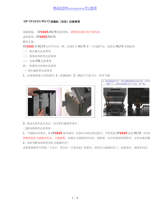
一)拆扫描头注意事项二)拆装加热组件注意事项三)安装ITB注意事项四)机器发出异响注意事项一)拆扫描组件注意事项1.注意拆卸着力点的部位: 1)机器底部;2)侧盖几个着力点。
参考下图:3. 两边分离开盖合页后,双手把扫描组件拿开。
二)拆加热组件注意事项1.下面拆打印部分,和CP1025基本相同。
在拆打印部分的过程中,不管是拆CP1025还是M175,打印机热组件的压力滚轴归位后,才能拆机。
如果压力滚轴没有归位,就拆机,以后回装加热组件时,会有安装问题。
2.如何判断加热组件的压力滚轴归位?查看加热组件中间第二个孔中,是否有一白色突起?如果有,说明压力滚轴归位了。
如果没有,则没有归位。
安装加热组件时, 确保加热组件释压驱动凸轮(红圈所标)保持下图所示位置。
即凸轮手柄处于最低端。
三)拆装ITB注意事项安装的ITB备件分两种来源:1)从机器上拆下来的ITB备件;2)从SRFR系统申请到的ITB备件。
1. 从机器上拆下来的ITB备件安装注意事项:回装ITB时,需注意ITB左边(从后面看)有个白色齿轮。
白色齿轮缺口应与侧面的一个小黑三角标记对齐,然后回装ITB。
红圈为白色齿轮缺口和小黑三角对应好的位置,如下图:2)安装SRFR到货新ITB注意事项:a.新到货ITB需要释放TIB弹簧。
可以用一字螺丝刀,把两边画圈的地方向内顶开,这时ITB会自动把皮带拉紧,如下图:b.安装新的ITB皮带时,注意左侧白色齿轮缺口应与小黑三角标记对应。
如果此白色齿轮和小黑三角没有对好,装上去后会发出咔咔声响。
c.新到的ITB备件有个桔红色的卡子,可以不用取出。
把ITB完全装入机器中,方可取出,如下图。

hp1005硒鼓hp1005硒鼓更换流程在我们办公室最常见的—打印机耗材都有一定的使用寿命,hp1005硒鼓额定寿命一般在6000-10000张左右,在经过长期使用以后,当你发现输出的稿件图像浅淡、有严重黑斑条纹,就算你再怎么保养修补也无济于事的时候,hp1005硒鼓的生命算是真正到了终点,这时就需要进行更换了。
更换硒鼓说难也不难,说容易但也不能大意处之,这其中还是有点学问的,下面就以鼓粉分离式的硒鼓为例,作一简单介绍。
首先,关闭打印机电源取出硒鼓,然后用钳子夹住一侧的金属销钉,用力小心向外拔出来(或直接把销钉钉进去,打开硒鼓后再取出来),一般情况下,这时我们可以发现硒鼓可以分成两部分,带有磁辊的是供粉部分,而有感光硒的是废粉的收集部分。
先来看供粉部分,先把磁辊无齿轮一侧的螺钉旋下,打开塑料盖,然后将碳粉仓内和磁辊上的碳粉全部用软毛刷等清理干净。
接着再把磁辊重新装好,用力按好防止磁辊脱离原位。
这时就可以装碳粉了,把碳粉摇匀后慢慢倒入供粉仓内,上好部件把磁辊固定好,最后应轻轻转动磁辊一端的齿轮数圈,以有利于碳粉的均匀贴附。
再来看看收集部分,在这部分我们要做的就是更换新的感光鼓。
用同样方法将固定销钉拨出,取出感光鼓,然后将废粉收集部分的废粉清理干净(要尽可能干净,以免影响新鼓的打印质量),到此,我们就可以安装新的感光鼓了。
安装时要注意,感光鼓通常都有左右之分的,把装有齿轮的一端对接装上后,用刚刚拨下的固定销钉上好感光鼓。
全新的感光鼓一般都有一条墨色的防曝光封条,在安装前不要撕下以防止曝光,安装好检查无误后方可撕去。
这样,供粉部分和收集部分都分别弄好了,最后只要把这两部分按拆开时的情况安装复原,插好固定卡销,整个更换工作便宣告完成。
在更换过程中,如果有碳粉落在打印机外面,最好用吸尘器吸除,再用纯酒精擦洗一遍。
而且,整个更换过程最好在较暗的工作室里进行,防止感光鼓曝光。
而对于一体式硒鼓的更换,可谓简单得很,只要把整个硒鼓拿下成套更换就可以了,省了不少麻烦,但在装入前记得最好把碳粉摇匀。

hp1005硒鼓2612a加粉图解1.加粉之前,需要把废粉完全清除,磁辊上的粉尽量用皮老鼠弄干净,如果加入的粉和原来的粉不一样,两个混在一起,很可能打印出来的效果有底灰。
2.磁辊部分:⑴磁辊两边都有个塑料辊套,加粉的时候注意不要弄坏,也不要忘记不装,如果不装或者坏掉,可能发生的效果是:不装的一边打印后有鱼鳞状粉底。
⑵磁辊的一边有个黄色的圈状铜丝,好像是接地把,注意不要把它弄弯,或者压成别的状,因为它的不良很可能影响到打印效果的深浅度(与原效果对比)。
3.橡胶辊:个人认为,如果以前打印效果好的话,加粉的时候不要擦试橡胶辊,就算很脏也不要管它,可以用皮老鼠吹下。
加粉后如果出趾嵯虺鱿值暮诘溃徽派厦娑嘤?道的(鼓芯坏的话应该是四道),应该考虑下橡胶辊的问题。
4.鼓芯:取出的鼓芯尽量与工具隔离开,小心用工具碰到,因为大家都知道,鼓芯这个东西及其娇贵,不小心碰到很可能就报废了,要非常小心。
简单说这些,哪里不对的,或者需要补充的,请大家说说。
最后提醒下,给客户加粉之前最好先打印个测试页,看看效果是不是很好,不好的给他们说明。
如果上去就盲目的加粉,等加好了,效果不好,或者是该换鼓芯了,你再给客户说,客户绝对不会承认,他们会认为你加粉加坏的,纵使你有理,也说不清。
惠普M1005MFP一体机采用的2612A硒鼓,同时也在下列HP打印机或一体机中通用。
所以,该硒鼓加粉图对下列机器型号通用。
HP M1005/3050/3052/3055HP 1010/1012/1015/1018/1020/1022/3015/3020/3030首先准备工具从左上依次为护目镜防尘口罩皮老虎脱脂棉自制改锥毛刷尖嘴钳电动起子橡胶手套没有什么比自己的身体健康更重要的了,碳粉是一种类似于塑料的化学品,有毒,并且不溶于水,吸入到肺中永远也不会被吸收掉。
所以防尘口罩一定要准备,千万不要怕被人笑。
左-----------------------------------------------------------------------------右。
惠普M1005扫描、打印、复印一体机,使用一段时间后,在玻璃面板的内部有赃物、灰尘
粘附,扫描时有白点、复印后有很多黑点,需擦拭玻璃内表面。
捣鼓了好久才解决了,现在
共享下过程,供各位网友参考。
清理内部的灰尘
打印机断电之后
从这个印刷的面
板开始
用刀片撬开这个
塑料皮,并用十
字口的螺丝钉拧
开;撬开后还可
粘贴紧密的。
拧开螺丝后,内
部的卡扣如图,
往放纸的一侧轻
拉即可取下。
将这个数据线轻
轻拔出,防止清
理过程中损坏接
头。
安装回时注
意有触角的面相
互接触,否则控
制面板上会没显
示的。
然后用很小的内
六角扳手拧开这
个面上的7个螺
钉。
拧万螺丝后在背
面有三个卡扣,
用内六角扳手等
轻轻顶一下即可
撬开。
到此,即可翻开玻璃进行清理。
最后逆向安装回原即可。
用的就是12A的鼓,就是第一篇加粉的那个鼓
打开盖子
这是用来开关的,左边一个,右边一个
首先就是擦下这个,看见上面那个卡口没有
往上顶一下,就可以下下来了
然后是卡最上面那个板子的,连着卡鼓的齿轮。
右边往下按,往右就可以抽出来
在来下后背
看见那3个螺丝,下下来后,双手托着下面,抬一下,就可以拿下来
这是连着面板的2条线
一条黑的,一条白的
在来下侧盖,看见下面的那个卡口了吧,顶一下,在来扒上面的就很轻松
下来了
这边是管面板的
轻轻一抽就可以了,从这里拿出来
上面第二层盖子一翻就开了
这是卡全面口子的
先把这按下去,在从上左右2边往上拉,一起用劲往后抽就出来了
把这边的线全部抽掉
就是这样了
下左边2个螺丝,右边一个
往上一拉就出来了。
HP1007使用的88A和HP1522NF使用的36A硒鼓结构机同,所以拆解方法一样!
88A/36A硒鼓加粉图解如下:
第一,准备好硒鼓,工具(十字镙丝刀,毛刷或吹风筒,等)以及碳粉.
第二,竖起硒鼓,或倾斜着托起硒鼓.
第三,用十字镙丝刀拆掉盖子上两颗的镙丝.
第四,拆下镙丝后,取下盖子
第五,按箭头方向前后滑行就可以使使粉仓与鼓分离(而不能左右方向去扳开)
第六,打开硒鼓
第七,将硒鼓分成两半
第八,拿起粉仓,准备拆镙丝
第九,拆开粉仓
第十,拿起鼓仓
第十一,拆开鼓仓,倒掉废粉
第十二,加好碳粉,准备拼好硒鼓
第十三,将盖子上的弹簧上好
第十四,上好盖子
第十五,上好盖子上的镙丝,做好外观清洁,收工。
另外,芯片的话,88A的可以不用换,但如果想计数的话,还是换一块好点!
而36A的用在HP1522NF上的话,会提示余量错误,用还是能用,但比较麻烦,所以,建议换一下好点!。
用的就是12A的鼓,就是第一篇加粉的那个鼓
打开盖子
这是用来开关的,左边一个,右边一个
首先就是擦下这个,看见上面那个卡口没有
往上顶一下,就可以下下来了
然后是卡最上面那个板子的,连着卡鼓的齿轮。
右边往下按,往右就可以抽出来
在来下后背
看见那3个螺丝,下下来后,双手托着下面,抬一下,就可以拿下来
这是连着面板的2条线
一条黑的,一条白的
在来下侧盖,看见下面的那个卡口了吧,顶一下,在来扒上面的就很轻松
下来了
这边是管面板的
轻轻一抽就可以了,从这里拿出来
上面第二层盖子一翻就开了
这是卡全面口子的
先把这按下去,在从上左右2边往上拉,一起用劲往后抽就出来了
把这边的线全部抽掉
就是这样了
下左边2个螺丝,右边一个
往上一拉就出来了。