PyroSiM中文版用户说明书
- 格式:docx
- 大小:2.81 MB
- 文档页数:74
pyrosim说明书翻译(精品)pyrosim说明书翻译(精品)6.4.1 停止和再启动一个重要的MISC 参数叫RESTART。
建立一个CHID.STOP 的文件在目录下。
重新开始, RESTART=.TRUE.需要添加到MISC行中。
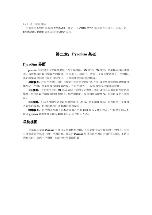
第二章:PyroSim基础PyroSim界面pyrosim为您建立火灾模型提供了四个编辑器:3D模式,2D模式,导航模式和记录模式。
这些都可以显示您现在的模型。
当添加了、移除了、或在一个模式中选择了一个物体,其它的模式也同时反映出这些变化。
下面简要介绍这几种模式。
导航视图:在这个视图下列出了模型中许多重要的记录。
它可以使您将您的模型中几何体组成一个组,例如组成房间或者沙发。
在这个模式下,定位和修改档案比较快捷。
3D视图:这个视图中以3D形式显示了您的火灾模型。
您可以以不同的视角查看您的模型。
您也可以控制模型的外观细节,如平滑阴影、纹理和物体轮廓线,也可以改变几何特征。
2D视图:在这个视图中您可以快速的画出几何体,例如墙和家具。
您可以从三个视角查看您的模型,也可以执行许多有用的几何操作。
档案视图:这个模式给出了为本次模拟产生的FDS输入文件的预览。
它提供了加入不经过pyrosim处理而直接输入FDS的自己的代码的方式。
导航视图导航视图是在Pyrosim主窗口左部的树状视图。
下图是使用这个视图的一个例子。
当你右键点击这个视图中的一个项目时,将显示Pyrosim可以在这个项目上执行的功能。
重新排列物体时,点选一个物体,然后拖转至新的位置。
在导航视图中使用菜单3D视图运用3D视图可以迅速得到模型的视觉外观。
导航选项包括标准CAD控制模式,Smokeview型的控制,游戏型的控制查看模型。
3D轨道导航点击激活3D轨道导航。
这个模式的控制方式与许多CAD程序的控制模式相似。
后,左键点击模型并移动鼠标,模型将会随着您点选的点选转。
旋转3D模型:点击点选(或按住ALT键)并竖向移动鼠标。
Application Notepyrogen or bacterial endotoxin test may be used in place of the in vivo rabbit pyrogen test, where appropriate.”Principle of the MATThe monocyte activation test (MAT) is the human in vitro alternative to the rabbit pyrogen test, and allows the detection of the full range of pyrogens, including endotoxins and non-endotoxin pyrogens (NEPs).By putting the product to be tested in contact withhuman monocytic cells, it will mimic what happens in the human body: in presence of pyrogens, the monocytes are activated and produce cytokines such as interleukin-6.The cytokines are then detected using an immunological assay (ELISA) involving specific antibodies and an enzymatic color reaction.Principle of the PyroMAT™ SystemThe PyroMAT™ System uses cryo-preserved Mono-Mac-6 (MM6) human monocytic cells as a source of monocytes. The response to pyrogenic substances is determined by measurement of interleukin-6 (IL-6) produced by the Mono-Mac-6 cells. For this purpose, the ELISA microplate supplied in the kit is coated with an antibody specific to IL-6.IL-6 molecules released by MM6 cells during incubation phase are transferred from the cells supernatant to the ELISA plate, and bound by the immobilized primary antibody.A secondary antibody, linked to an enzyme, is added to form an IL-6 bound complex. After washing anyunbound molecules, the IL-6 bound complex is detected in a color reaction started by the addition of an appropriate substrate.The color development is proportional to the amount of initial IL-6 production in the supernatant and measured with an absorbance reader.Reference Standard Endotoxins suitable for PyroMAT™ SystemIntroductionWhat is a pyrogen?A pyrogen is, by definition, a substance that produces a rise in temperature in a human or animal. Pyrogens constitute a heterogeneous group of contaminantscomprising microbial and non-microbial substances. The most widely known pyrogen is the endotoxin (LPS =Lipo-Polysaccharide), which is produced by gram-negative bacteria. Other microbial substances include thosederived from gram-positive bacteria like Lipoteichoic Acid (LTA), particles from viruses and pyrogens originating from yeasts and fungi. Non-microbial pyrogenicsubstances can be rubber particles, microscopic plastic particles or metal compounds in elastomers.Why to conduct a pyrogen test?Pyrogenic substances in pharmaceutical products can induce life-threatening fever reactions after injection into the human body. Therefore, it is a regulatory requirement to test such products for pyrogens to ensure product quality and patient safety.Purpose of the test is to prove that the amount of pyro-gens contained in the product will not exceed a certain threshold, known as the contaminant limit concentration (CLC), that will guarantee the patient safety.The monocyte activation test (MAT) method has been qualified and validated for the detection of pyrogens by the European Center for the Validation of Alternative Methods (ECVAM) in 2005 and by the InteragencyCoordinating Committee on the Validation of Alternative Methods (ICCVAM) in 2008.It has been among the compendial methods for pyrogen detection in the European Pharmacopeia since 2010 (Chapter 2.6.30). The MAT is also mentioned by the FDA "Guidance For Industry – Pyrogen and Endotoxins testing: Questions and Answers" as an alternative to the rabbit pyrogen test which should be validated according to USP <1225>. Additionally, the USP <151> Pyrogen Test mentions that, "A validated, equivalent in vitroThe life science business of Merck operates as MilliporeSigma in the U.S. and Canada.2Resuspension of RSELyophilized RSE were reconstituted and aliquoted according to supplier guidelines.Dilution of Reference Standard Endotoxin aliquotsThe standard endotoxin solutions were prepared from the RSE stock solution at 2000 EU/mL. Seven (7) endotoxin concentrations (0.0125, 0.025, 0.05, 0.1,0.2, 0.4, and 0.8 EU/mL) were prepared to generate the standard curve according to the following procedure:• Thaw a 50 µL-aliquot of RSE and vortex at maximum speed during 1 min.• Perform serial dilutions in endotoxin-free water, using endotoxin-free glass tubes, as described below. Make sure to vortex all the dilutions before using.Comparison of Reference Standard Endo-toxins (RSE) from different suppliersPreparation of endotoxin standard solutions is needed to assess the limit of detection (LOD) of the system, to build a standard curve for quantification or to estimate the pyrogen content of a sample, depending on the MAT method used.The use of a validated Reference Standard Endotoxin is required and such a standard can be supplied by the European Pharmacopeia (EDQM) or the United States Pharmacopeia (USP).Control Standard Endotoxins (CSE) provided by LAL suppliers should not be used for MAT test.The reference standard endotoxin (RSE) supplied by the USP / EDQM is a reference endotoxin preparation with a certified activity upon reconstitution. Control standard endotoxin preparations (CSEs) are qualified using the RSE, but their activity is certified only in combination with a test system, e.g. a defined preparation of limulus amoebocyte lysate used for the bacterial endotoxin test. Using these CSEs outside their test system might lead to unexpected results and is not recommended by the respective suppliers. As there is currently no dedicated reference standard for the pyrogen test available,standardization is achieved using a strong pyrogen like the RSE whose production and standardization is not depending on the use of a specific bacterial endotoxin test.The scope of this application note is to show the suitability of Reference Standard Endotoxins from different suppliers (USP/EDQM) for MAT with the PyroMAT™ System.PyroMAT™ Kit Pyr0MATkit PyroMAT™ Cells Pyr0MATcellsPyroMAT™ Endotoxin StandardEuropean Pharmacopoeia (EP) Reference Standard Endotoxin1.44161.0001Sigma-Aldrich RSEEuropean Pharmacopoeia (EP) Reference Standard EndotoxinE0150000ACILA RSE USP Reference Standard Endotoxin (USP) 10.000 E.U./Fl1220200NIBSC RSE 3rd International Standard 10,000 USP Endotoxin units Replacement I.S. for 94/58010/178Table 1: Materials used to generate standard curvesMaterialsFigure 2:Materials used to generate standard curves3MAT quick procedure with PyroMAT™Step 1: Preparation and incubation with PyroMAT™ cellsStep 2: Detection of IL-6 with ELISA1• Prepare suitable endotoxin standard dilutions• Load the different solutions on the 96-wells cell culture plate • Prepare the PyroMAT™ cells and dispense in each well2• Incubate the plate for 22 ±2 hours at 37 °C with humidified atmosphere, without CO 23• Transfer the cell supernatants into IL-6 microplate• Add the IL-6 conjugate to each well • Incubate 2 hours at room temperature 4• Remove the liquid and wash the plate 4 times• Prepare the substrate solution by mixing color reagent A and B and add the mixture to each well • Incubate 30 minutes at room temperature, in the dark5• Add the stop solution6• Read the plate at 450 nm and 630 nm within 30 minutes after adding the stop solutionFigure 3: PyroMAT TMworkflow with standard ELISA procedureResultsEndotoxin standard curves were generated using RSE from different suppliers. To be considered “VALID”, the endotoxin standard curve must fulfill the following acceptance criteria described in the EP Chapter 2.6.30 : Effect of dose criteria: a statistical test thatconfirms a positive dose/effect response.Goodness of fit: a statistical test that confirms the suitability of the regression model to describe the raw data. The data are modeled with a 5-parameter logistics regression model.Blank criteria: the mean of blank OD value should be below 0.1.LOD criteria: the test is valid if an LOD ≤ 0.05 EU/mL is reached.An additional criterion was implemented in the protocol to assess the reactivity of the standard curve:Minimum of reactivity: OD of the 4 replicates of the highest standard (0.8 EU/mL) should be above 3.It is not required by the European pharmacopeia and is given as an additional indication for the customer.Data analysis was performed using the PyroMAT™data analysis tool, which consists of a specific protocol developed for PyroMAT™ using Gen5 Software (Biotek).The Figure 4 presents the curves that were obtained with the PyroMAT™ system using Reference Standard Endotoxins (RSE) from four different suppliers as described in table 1.Figure 4: Comparison of standard curves generated with various Reference Standard EndotoxinsThe validity of the acceptance criteria for the endotoxin standard curve was determined using the PyroMAT™ data analysis tool (protocol for Gen5 Software).The Figure 5 shows the results obtained and the legend used in the software for data interpretation:All standard curves generated with RSE from different suppliers passed the acceptance criteria of a valid standard curve according to the EP chapter 2.6.30.ConclusionAll four different Reference Standard Endotoxins (RSE) tested led to the generation of a valid standard curve and can be used to perform MAT with PyroMAT™ system.MaterialEffect of close Goodness of Fit Blank Delta OD LOD criteria Minimum of reactivityPyroMAT™ Endotoxin Standard VALID VALID VALID VALID CONFORM Sigma-Aldrich RSE VALID VALID VALID VALID CONFORM ACILA RSE VALID VALID VALID VALID CONFORM NIBSC RSEVALIDVALIDVALIDVALIDCONFORMLegendEffect of Dose Criteria: VALID: p<0.01 LOD Criteria VALID: LOD ≤ 0.05 EU/mLINVALID: p≥0.01INVALID:LOD > 0.05 EU/mLGoodness of Fit Criteria: VALID: p>0.05 Additional Criteria – Minimum of reactivity CONFORM: All replicates of Delta OD at STD7 are above 3INVALID: p≤0.05 NOT REACHED: At least one replicate of Delta OD at STD7 is below 3BLK Delta OD Criteria: VALID: MEAN(BLK)<0.1 : Unable to EvaluateINVALID: MEAN(BLK)≥0.1Figure 5: Acceptance criteria for the endotoxin standard curves and legend for data interpretationTo place an order or receive technical assistanceIn Europe, please call Customer Service:France: 0825 045 645 Germany************ I taly: 848 845 645Spain: 901 516 645 Option 1Switzerland: 0848 645 645UnitedKingdom************For other countries across Europe, p lease call: +44 (0) 115 943 0840 Or visit: /officesFor Technical Service visit: /techservice /pyromatMerck, the vibrant M, Millipore and PyroMAT are trademarks of Merck KGaA or its afiliates. All other trademarks are the property of their respective owners. Detailed information on trademarks is available via publicly accessible resources.© 2018 Merck KGaA, Darmstadt, Germany and/or its affiliates. All Rights Reserved.MK_AN2150EN 2018-1255306/2018Merck KGaAFrankfurter Str. 250 64293 Darmstadt。
点击OK后,网格就生成了,如下图所示:1.3 定义粒子这里的粒子并不是通常CFD软件里的拉格朗日粒子,只是为了后处理方便而定义的示踪粒子。
选择Model > Edit Particles ...,然后点New。
不要选Particle Have Mass,这样粒子没有质量,仅是示踪粒子。
选中Color Particles During Animation,使用默认的颜色,红色。
这样在结果中会有红色的示踪粒子。
1.4 建立面实际上,在建立网格的时候,我们已经得到了计算模型。
这里的面是用来定义边界条件。
要注意的是,这里仅仅定义边界条件,而没有给模型中的面指定边界条件。
也就是说只定义边界上的物理条件,但并没有和模型中的边界联系起来。
定义入口边界。
Model > Edit Surface Properties ...,点New。
Surface name是BLOW,使用INERT作为模板。
选择surface type为"Fan/Wind”。
然后下面会有很多选项。
系统定义的表面类型都有明确的物理意义,还是比较好懂的。
Fan/Wind里可以定义入口空气的温度和速度。
为了便于区分,把Color选成蓝色。
Air Temperature = 20 C,Specify Normal Velocity = -1.0 m/s。
-1.0 m/s代表气流速度为1m/s,方向为进入计算域(+1.0m/s为出)。
第三个标签下,选中Emit Particles,Particle Type = PART。
最后点OK。
各步骤的截图如下:在这里例子里面,只需要定义BLOW这一个面,其余的面可以用系统定义的来表示。
1.5 定义边界条件这里是真正指定表面的边界条件。
定义入口。
选择Model > New Vent ...,在Specification标签下,Description = Vent Blow,Type = BLOW,Lies in the plane X = 0.0,Min Y = 3,Max Y = 7,Min Z = 3,Max Z = 7。
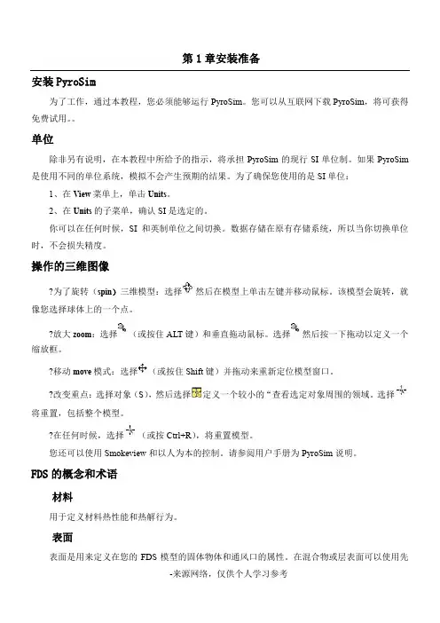
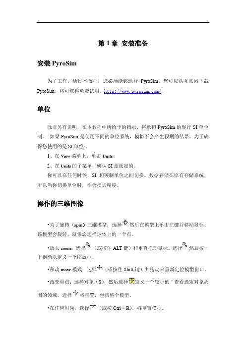
第1章安装准备安装PyroSim为了工作,通过本教程,您必须能够运行PyroSim。
您可以从互联网下载PyroSim,将可获得免费试用。
单位除非另有说明,在本教程中所给予的指示,将承担PyroSim的现行SI单位制。
如果PyroSim 是使用不同的单位系统,模拟不会产生预期的结果。
为了确保您使用的是SI单位:1、在View菜单上,单击Units。
2、在Units的子菜单,确认SI是选定的。
你可以在任何时候,SI和英制单位之间切换。
数据存储在原有存储系统,所以当你切换单位时,不会损失精度。
操作的三维图像?为了旋转(spin)三维模型:选择然后在模型上单击左键并移动鼠标。
该模型会旋转,就像您选择球体上的一个点。
?放大zoom:选择(或按住ALT键)和垂直拖动鼠标。
选择然后按一下拖动以定义一个缩放框。
?移动move模式:选择(或按住Shift键)并拖动来重新定位模型窗口。
?改变重点:选择对象(S),然后选择定义一个较小的“查看选定对象周围的领域。
选择将重置,包括整个模型。
?在任何时候,选择(或按Ctrl+R),将重置模型。
您还可以使用Smokeview和以人为本的控制。
请参阅用户手册为PyroSim说明。
FDS的概念和术语材料用于定义材料热性能和热解行为。
表面表面是用来定义在您的FDS模型的固体物体和通风口的属性。
在混合物或层表面可以使用先前定义的材料。
默认情况下,所有的固体物体和通风口都是有惰性的,一个固定的温度,初始温度。
障碍物障碍物的根本在火灾动力学模拟的几何表示(FDS)[FDS-SMV的官方网站]。
障碍物两点定义在三维的矩形固体空间。
表面特性,被分配到每个面对的阻挠。
设备和控制逻辑可以定义创建或删除在模拟过程中的一个障碍。
当创建一个模型,障碍物的几何形状并不需要相匹配的几何网格的解决方案中使用。
然而,产品安全的解决方案将配合所有几何解决方案网状。
在FDS分析,阻塞所有的面转移到对应最近的网状细胞。
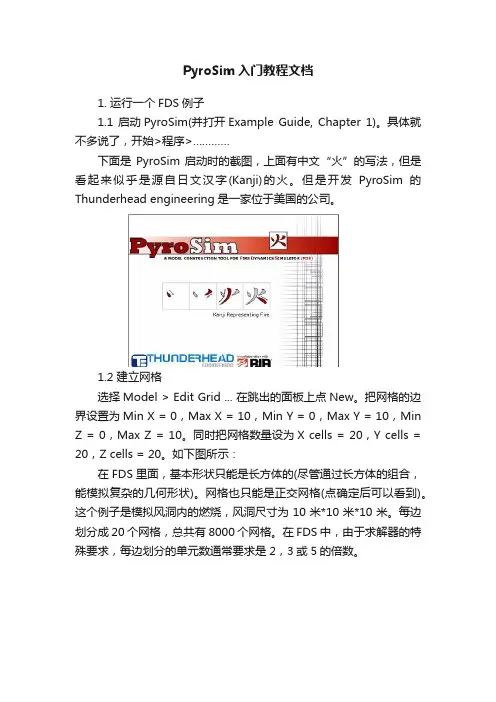
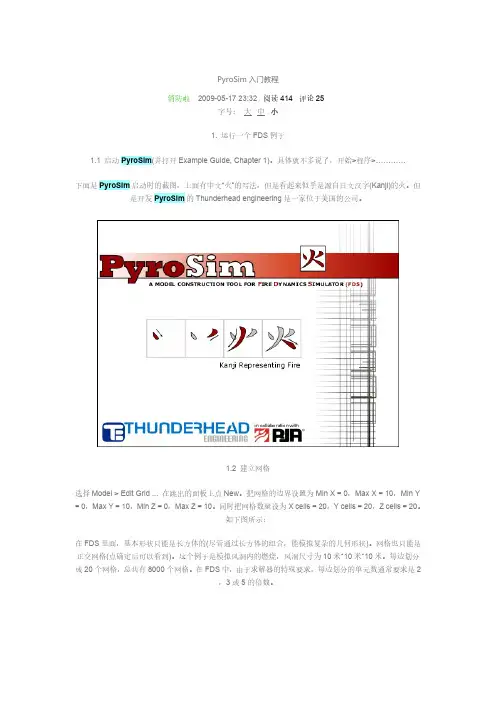
PyroSim入门教程文档1. 运行一个FDS例子1.1 启动PyroSim(并打开Example Guide, Chapter 1)。
具体就不多说了,开始>程序>…………下面是PyroSim启动时的截图,上面有中文“火”的写法,但是看起来似乎是源自日文汉字(Kanji)的火。
但是开发PyroSim的Thunderhead engineering是一家位于美国的公司。
1.2 建立网格选择Model > Edit Grid ... 在跳出的面板上点New。
把网格的边界设置为Min X = 0,Max X = 10,Min Y = 0,Max Y = 10,Min Z = 0,Max Z = 10。
同时把网格数量设为X cells = 20,Y cells = 20,Z cells = 20。
如下图所示:在FDS里面,基本形状只能是长方体的(尽管通过长方体的组合,能模拟复杂的几何形状)。
网格也只能是正交网格(点确定后可以看到)。
这个例子是模拟风洞内的燃烧,风洞尺寸为10米*10米*10米。
每边划分成20个网格,总共有8000个网格。
在FDS中,由于求解器的特殊要求,每边划分的单元数通常要求是2,3或5的倍数。
点击OK后,网格就生成了,如下图所示:1.3 定义粒子这里的粒子并不是通常CFD软件里的拉格朗日粒子,只是为了后处理方便而定义的示踪粒子。
选择Model > Edit Particles ...,然后点New。
不要选Particle Have Mass,这样粒子没有质量,仅是示踪粒子。
选中Color Particles During Animation,使用默认的颜色,红色。
这样在结果中会有红色的示踪粒子。
1.4 建立面实际上,在建立网格的时候,我们已经得到了计算模型。
这里的面是用来定义边界条件。
要注意的是,这里仅仅定义边界条件,而没有给模型中的面指定边界条件。
也就是说只定义边界上的物理条件,但并没有和模型中的边界联系起来。
Package‘sims’October14,2022Title Simulate Data from R or'JAGS'CodeVersion0.0.3Description Generates data from R or'JAGS'code for use in simulationstudies.The data are returned as an'nlist::nlists'object and/orsaved tofile as individual'.rds'files.Parallelization isimplemented using the'future'package.Progress is reported usingthe'progressr'package.License MIT+file LICENSEDepends R(>=3.6)Imports chk,future.apply,nlist,parallel,stats,yesnoSuggests covr,future,knitr,progressr,rjags,rmarkdown,testthat(>=3.0.0),withrVignetteBuilder knitrEncoding UTF-8Language en-USRoxygenNote7.1.2Config/testthat/edition3NeedsCompilation noAuthor Audrey Beliveau[aut],Joe Thorley[aut,cre](<https:///0000-0002-7683-4592>)Maintainer Joe Thorley<************************>Repository CRANDate/Publication2021-09-2018:50:02UTCR topics documented:sims_add (2)sims_check (2)sims_copy (3)sims_data (4)12sims_check sims_data_files (4)sims_info (5)sims_rdists (5)sims_simulate (6)Index8 sims_add Add Simulated DatasetsDescriptionAdd Simulated DatasetsUsagesims_add(path=".",nsims=1)Argumentspath A string specifying the path to the directory to add the data sets to.nsims A count of the number of additional datasets to generate.ValueA character vector of the names of thefiles created.sims_check Check Simulated DataDescriptionChecks the simulated data argument values in the’.sims.rds’file.Usagesims_check(path=".")Argumentspath A string of the path to the directory with the simulated data.DetailsThe checks include whether number and names of the datafiles in the directory are consistent with the number of simulations.sims_copy3 ValueAn informative error or invisible list of the argument values.Examplesset.seed(10)sims_simulate("a<-runif(1)",save=TRUE,path=tempdir(),exists=NA,ask=FALSE)(sims_check(tempdir()))sims_copy Copy Simulated DatasetsDescriptionCopy Simulated DatasetsUsagesims_copy(path_from=".",path_to=paste0(path_from,"_copy"),exists=FALSE,ask=getOption("sims.ask",TRUE),silent=FALSE)Argumentspath_from A string of the path to the directory containing the simulated datasets.path_to A string of the path to the directory to copy the simulated dataset to.exists Aflag specifying whether path_to should already exist.If exists=NA it doesn’t matter.If the directory already exists sims compatiblefiles are deletedif exists=TRUE or exists=NA otherwise an error is thrown.ask Aflag specifying whether to ask before deletingfiles.silent Aflag specifying whether to suppress warnings.ValueA character vector of the names of thefiles copied.4sims_data_files sims_data Simulated DatasetsDescriptionGets the simulated datasets as an nlist::nlists_object().There is no guarantee that all the datasets willfit in memory.Usagesims_data(path=".")Argumentspath A string of the path to the directory with the simulated data.ValueAn nlist::nlists_object()of the simulated datasets.Examplesset.seed(10)sims_simulate("a<-runif(1)",nsims=10L,path=tempdir(),exists=NA,ask=FALSE)library(nlist)sims_data(tempdir())sims_data_files Simulated Data FilesDescriptionGets the names of the simulated datafiles.Usagesims_data_files(path=".")Argumentspath A string of the path to the directory with the simulated data.ValueA character vector of the names of the simulated datafiles.sims_info5Examplesset.seed(10)sims_simulate("a<-runif(1)",nsims=10L,path=tempdir(),exists=NA,ask=FALSE)sims_data_files(tempdir())sims_info Simulated Data Argument ValuesDescriptionGets the simulated data argument values in the’.sims.rds’file.Usagesims_info(path=".")Argumentspath A string of the path to the directory with the simulated data.ValueA named list of the values in file.path(path, .sims.rds ).Examplesset.seed(10)sims_simulate("a<-runif(1)",path=tempdir(),exists=NA,ask=FALSE)sims_info(tempdir())sims_rdists Sims Random R DistributionsDescriptionGets the names of the R random variate generating functions listed in Distributions().Usagesims_rdists()ValueA character vector.Examplessims_rdists()sims_simulate Simulate DatasetsDescriptionSimulates datasets using JAGS or R code.By default returns the datasets as an nlist::nlists_object().If path is provided then the datasets are written to the directory as individual.rdsfiles.Usagesims_simulate(code,constants=nlist::nlist(),parameters=nlist::nlist(),monitor=".*",stochastic=NA,latent=NA,nsims=1,save=FALSE,path=".",exists=FALSE,rdists=sims_rdists(),ask=getOption("sims.ask",TRUE),silent=FALSE)Argumentscode A string of the JAGS or R code to generate the data.The JAGS code must notbe in a data or model block.constants An nlist object(or list that can be coerced to nlist)specifying the values of nodesin code.The values are included in the output dataset.parameters An nlist object(or list that can be coerced to nlist)specifying the values of nodesin code.The values are not included in the output dataset.monitor A character vector(or regular expression if a string)specifying the names of thenodes in code to include in the dataset.By default all nodes are included.stochastic A logical scalar specifying whether to monitor deterministic and stochastic(NA),only deterministic(FALSE)or only stochastic nodes(TRUE).latent A logical scalar specifying whether to monitor observed and latent(NA),onlylatent(TRUE)or only observed nodes(FALSE).nsims A whole number between1and1,000,000specifying the number of data sets tosimulate.By default1data set is simulated.save Aflag specifying whether to return the data sets as an nlists object or save inpath.If save=NA the datasets are returned as an nlists object and saved inpath.path A string specifying the path to the directory to save the data sets in.exists Aflag specifying whether the path directory should already exist(if exists=NA it doesn’t matter).rdists A character vector specifying the R functions to recognize as stochastic.ask Aflag specifying whether to ask before deleting sims compatiblefiles.silent Aflag specifying whether to suppress warnings.DetailsJAGS code is identified by the presence of’~’indicating a stochastic variable node.Otherwise codeis assumed to be R code and stochastic variable nodes are those where assignment is immediatelysucceeded by a call to one of the functions named in rdists.Both constants and parameters must be[nlist::nlist_object]s(or lists that can be coerced tosuch).The only difference between constants and parameters is that the values in constants areappended to the output data while the values in parameters are not.Neither constants or parameterscan include missing values nor can they have elements with the same name.Elements which are notin code are dropped with a warning(unless silent=TRUE in which case the warning is suppressed).Each set of simulated data set is written as a separate.rdsfile.Thefiles are labelled data0000001.rds,data0000002.rds,data0000003.rds etc.The argument values are saved in the hiddenfile.sims.rds.sims compatiblefiles are those matching the regular expression^((data\\\\d\{7,7\})|([.]sims))[.]rds$.Parallelization is implemented using the future package.ValueBy default an nlist::nlists_object()of the simulated data.Otherwise if path is defined savesthe datasets as individual.rdsfiles and returns TRUE.See Alsosims_rdists()Examplesset.seed(101)sims_simulate("a<-runif(1)",path=tempdir(),exists=NA,ask=FALSE)IndexDistributions(),5nlist::nlists_object(),4,6,7sims_add,2sims_check,2sims_copy,3sims_data,4sims_data_files,4sims_info,5sims_rdists,5sims_rdists(),7sims_simulate,68。
第1章安装准备安装PyroSim为了工作,通过本教程,您必须能够运行PyroSim。
您可以从互联网下载PyroSim,将可获得免费试用。
单位除非另有说明,在本教程中所给予的指示,将承担PyroSim的现行SI单位制。
如果PyroSim 是使用不同的单位系统,模拟不会产生预期的结果。
为了确保您使用的是SI单位:1、在View菜单上,单击Units。
2、在Units的子菜单,确认SI是选定的。
你可以在任何时候,SI和英制单位之间切换。
数据存储在原有存储系统,所以当你切换单位时,不会损失精度。
操作的三维图像?为了旋转(spin)三维模型:选择然后在模型上单击左键并移动鼠标。
该模型会旋转,就像您选择球体上的一个点。
?放大zoom:选择(或按住ALT键)和垂直拖动鼠标。
选择然后按一下拖动以定义一个缩放框。
?移动move模式:选择(或按住Shift键)并拖动来重新定位模型窗口。
?改变重点:选择对象(S),然后选择定义一个较小的“查看选定对象周围的领域。
选择将重置,包括整个模型。
?在任何时候,选择(或按Ctrl+R),将重置模型。
您还可以使用Smokeview和以人为本的控制。
请参阅用户手册为PyroSim说明。
FDS的概念和术语材料用于定义材料热性能和热解行为。
表面表面是用来定义在您的FDS模型的固体物体和通风口的属性。
在混合物或层表面可以使用先前定义的材料。
默认情况下,所有的固体物体和通风口都是有惰性的,一个固定的温度,初始温度。
障碍物障碍物的根本在火灾动力学模拟的几何表示(FDS)[FDS-SMV的官方网站]。
障碍物两点定义在三维的矩形固体空间。
表面特性,被分配到每个面对的阻挠。
设备和控制逻辑可以定义创建或删除在模拟过程中的一个障碍。
当创建一个模型,障碍物的几何形状并不需要相匹配的几何网格的解决方案中使用。
然而,产品安全的解决方案将配合所有几何解决方案网状。
在FDS分析,阻塞所有的面转移到对应最近的网状细胞。
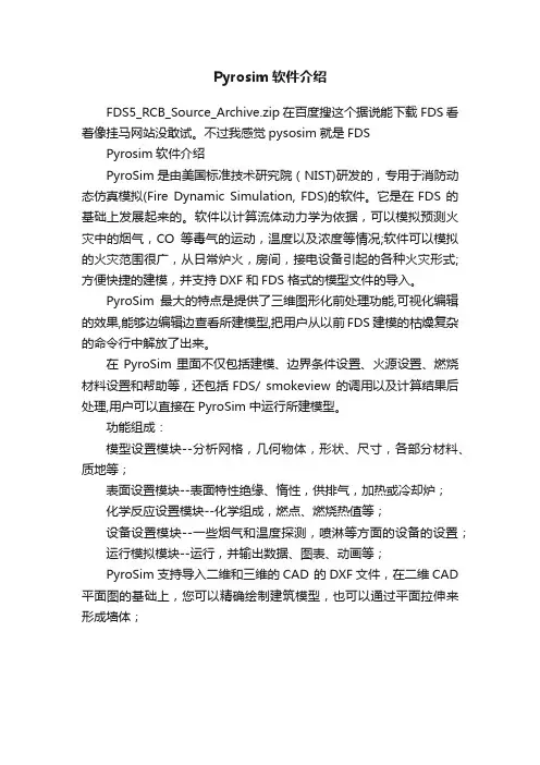
Pyrosim软件介绍
FDS5_RCB_Source_Archive.zip 在百度搜这个据说能下载FDS 看着像挂马网站没敢试。
不过我感觉pysosim就是FDS
Pyrosim软件介绍
PyroSim是由美国标准技术研究院(NIST)研发的,专用于消防动态仿真模拟(Fire Dynamic Simulation, FDS)的软件。
它是在FDS 的基础上发展起来的。
软件以计算流体动力学为依据,可以模拟预测火灾中的烟气,CO等毒气的运动,温度以及浓度等情况;软件可以模拟的火灾范围很广,从日常炉火,房间,接电设备引起的各种火灾形式;方便快捷的建模,并支持DXF和FDS 格式的模型文件的导入。
PyroSim最大的特点是提供了三维图形化前处理功能,可视化编辑的效果,能够边编辑边查看所建模型,把用户从以前FDS 建模的枯燥复杂的命令行中解放了出来。
在PyroSim里面不仅包括建模、边界条件设置、火源设置、燃烧材料设置和帮助等,还包括FDS/ smokeview 的调用以及计算结果后处理,用户可以直接在PyroSim中运行所建模型。
功能组成:
模型设置模块--分析网格,几何物体,形状、尺寸,各部分材料、质地等;
表面设置模块--表面特性绝缘、惰性,供排气,加热或冷却炉;
化学反应设置模块--化学组成,燃点、燃烧热值等;
设备设置模块--一些烟气和温度探测,喷淋等方面的设备的设置;
运行模拟模块--运行,并输出数据、图表、动画等;
PyroSim支持导入二维和三维的CAD 的DXF文件,在二维CAD 平面图的基础上,您可以精确绘制建筑模型,也可以通过平面拉伸来形成墙体;。
第1章安装准备安装PyroSim为了工作,通过本教程,您必须能够运行PyroSim。
您可以从互联网下载PyroSim,将可获得免费试用。
/。
单位除非另有说明,在本教程中所给予的指示,将承担PyroSim的现行SI单位制。
如果PyroSim是使用不同的单位系统,模拟不会产生预期的结果。
为了确保您使用的是SI单位:1、在View菜单上,单击Units。
2、在Units的子菜单,确认SI是选定的。
你可以在任何时候,SI和英制单位之间切换。
数据存储在原有存储系统,所以当你切换单位时,不会损失精度。
操作的三维图像•为了旋转(spin)三维模型:选择然后在模型上单击左键并移动鼠标。
该模型会旋转,就像您选择球体上的一个点。
•放大zoom:选择(或按住ALT键)和垂直拖动鼠标。
选择然后按一下拖动以定义一个缩放框。
•移动move模式:选择(或按住Shift键)并拖动来重新定位模型窗口。
•改变重点:选择对象(S),然后选择定义一个较小的“查看选定对象周围的领域。
选择将重置,包括整个模型。
•在任何时候,选择(或按Ctrl + R),将重置模型。
您还可以使用Smokeview和以人为本的控制。
请参阅用户手册为PyroSim 说明。
FDS的概念和术语材料用于定义材料热性能和热解行为。
表面表面是用来定义在您的FDS模型的固体物体和通风口的属性。
在混合物或层表面可以使用先前定义的材料。
默认情况下,所有的固体物体和通风口都是有惰性的,一个固定的温度,初始温度。
障碍物障碍物的根本在火灾动力学模拟的几何表示(FDS)[FDS- SMV的官方网站]。
障碍物两点定义在三维的矩形固体空间。
表面特性,被分配到每个面对的阻挠。
设备和控制逻辑可以定义创建或删除在模拟过程中的一个障碍。
当创建一个模型,障碍物的几何形状并不需要相匹配的几何网格的解决方案中使用。
然而,产品安全的解决方案将配合所有几何解决方案网状。
在FDS分析,阻塞所有的面转移到对应最近的网状细胞。
6.4.1 停止和再启动一个重要的MISC 参数叫RESTART。
建立一个CHID.STOP 的文件在目录下。
重新开始,RESTART=.TRUE.需要添加到MISC行中。
第二章:PyroSim基础PyroSim界面pyrosim为您建立火灾模型提供了四个编辑器:3D模式,2D模式,导航模式和记录模式。
这些都可以显示您现在的模型。
当添加了、移除了、或在一个模式中选择了一个物体,其它的模式也同时反映出这些变化。
下面简要介绍这几种模式。
导航视图:在这个视图下列出了模型中许多重要的记录。
它可以使您将您的模型中几何体组成一个组,例如组成房间或者沙发。
在这个模式下,定位和修改档案比较快捷。
3D视图:这个视图中以3D形式显示了您的火灾模型。
您可以以不同的视角查看您的模型。
您也可以控制模型的外观细节,如平滑阴影、纹理和物体轮廓线,也可以改变几何特征。
2D视图:在这个视图中您可以快速的画出几何体,例如墙和家具。
您可以从三个视角查看您的模型,也可以执行许多有用的几何操作。
档案视图:这个模式给出了为本次模拟产生的FDS输入文件的预览。
它提供了加入不经过pyrosim处理而直接输入FDS的自己的代码的方式。
导航视图导航视图是在Pyrosim主窗口左部的树状视图。
下图是使用这个视图的一个例子。
当你右键点击这个视图中的一个项目时,将显示Pyrosim可以在这个项目上执行的功能。
重新排列物体时,点选一个物体,然后拖转至新的位置。
在导航视图中使用菜单3D视图运用3D视图可以迅速得到模型的视觉外观。
导航选项包括标准CAD控制模式,Smokeview型的控制,游戏型的控制查看模型。
3D轨道导航点击激活3D轨道导航。
这个模式的控制方式与许多CAD程序的控制模式相似。
旋转3D模型:点击后,左键点击模型并移动鼠标,模型将会随着您点选的点选转。
点选(或按住ALT键)并竖向移动鼠标。
选择后点击并拖动来定义缩放范围。
点选(或按住SHIFt键)并拖动,可以移动模型在窗口中的位置。
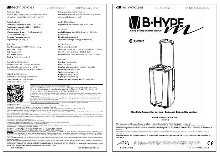
Quick start user manualSection 1The warnings in this manual must be observed together with the "USER MANUAL - Section 2".Le avvertenze nel presente manuale devono essere osservate congiuntamente al “MANUALE D’USO - Sezione2”.Die Warnungen in diesem Handbuch müssen in Verbindung mit der "BEDIENUNGSANLEITUNG - Abschnitt 2" beobachtet werden”.Les avertissements specifiés dans ce manuel doivent être respectés ainsi que les "CARACTERISTIQUES TECHNIQUES -Section 2"Las advertencias del presente manual se deben tener en cuenta conjuntamente con las del “MANUAL DEL USUARIO” - Sección 2”.A.E.B. Industriale Srl Via Brodolini, 8 Località Crespellano 40053 VALSAMOGGIA BOLOGNA (ITALIA)Technical DataSpeaker Type : 2-way battery speaker with wireless microphone (handheld or bodypack versions)Acoustical dataFrequency Response [-10 dB]: 62 – 20000 Hz Frequency Response [-6 dB]: 66 – 18100 Hz Max SPL (1 m): 123 dBHF compression driver : 1" Exit (voice coil : 1”) LF : 10” (voice coil : 1.5”)Crossover frequency : 2400 Hz Dispersion : 90° (H) x 45° (V)AmplifierAmp Technology : Amp SMPS Power Supply Amp Class : Class-D RMS Power : 95 WPeak Power: 190 WCooling: Passive (convection)Operating voltage range:220-240V~/100-120V~ 50-60 Hz (factory set) Operating temperature: [-10 +55] °CCharger operating temperature: [-0 +44] °CB-HYPE MOBILE batteryBattery type : LI-Ion (25.9 V / 2200 mAh) Charging time: Less than 2 hours Mean usage time: 4 hoursIntegrated transmitter ChargerRechargeable Device: HT-BHM handheld only (Ni-MH rechargeable batteries only)Audio Media PlayerSupported audio formats: .mp3, .wav, .wmaRF sectionAvailable bands: 542-566 / 638-662 / 863-865 MHz (factory set)RF selectable channels: 8Transmission range: up to 35 m (114.82 in)Input / OutputMains connections : VDESignal I/O : (Balanced) 1x combo (XLR/TRS) IN, 1x stereo RCA IN, 1x mini-jack IN, 1 x TRS link OUTMixer controls: Volume controls, EQ, CH1/RF priorityMechanicsHousing: Plastic cabinet Grille : Full grilleHandles : 1 for each side, 1 on top (retractable) Mounting pole: yes, 36 mm Width : 300 mm (11.81 in) Height : 568 mm (22.36 in)Depth : 301 mm (11.86 in)Weight (without transmitter): 12.5 kg (27 lbs.)Download the complete user manual on: /EN/Downloads.aspx , or scan with your QR Reader App to download it. EMI CLASSIFICATIONAccording to the standards EN 55103 this equipment is designed and suitable to operate in CLASS B Electromagnetic environments. FCC CLASS B STATEMENT ACCORDING TO TITLE 47, PART 15, SUBPART B, §15.105This equipment has been tested and found to comply with the limits for a Class B digital device, pursuant to part 15 of the FCC Rules. These limits are designed to provide reasonable protection against harmful interference in a residential installation.This equipment generates, uses and can radiate radio frequency energy and, if not installed and used in accordance with the instructions, may cause harmful interference to radio communications.However, there is no guarantee that interference will not occur in a particular installation. If this equipment does cause harmful interference to radio or television reception, which can be determined by turning the equipment off and on, the user is encouraged to try to correct the interference by one or more of the following measures:1. Reorient or relocate the receiving antenna.2. Increase the separation between the equipment and receiver.3. Connect the equipment into an outlet on a circuit different from that to which the receiver is connected.4. Consult the dealer or an experienced radio/TV technician for help.Changes or modifications not expressly approved by the party responsible for compliance could void the user’s authority to operate the equipment.B-HYPE MOBILE contains transmitter module:HANDHELD VERSION Æ FCC ID:2ADDV-HTBHM (USA) IC:12207A-HTBHM (CANADA) BODYPACK VERSION Æ FCC ID: 2ADDV-BTBHM (USA) IC: 12207A-BTBHM (CANADA)WARNING: Make sure that the loudspeaker is securely installed in a stable position to avoid any injuries or damages to persons or properties. For safety reasons do not place one loudspeaker on top of another without proper fastening systems. Before hanging the loudspeaker check all the components for damages, deformations, missing or damaged parts that may compromise safety during installation. If you use the loudspeakers outdoor avoid spots exposed to bad weather conditions.Contact dB Technologies for accessories to be used with speakers. dBTechnologies will not accept any responsibility for damages caused by inappropriate accessories or additional devices.Features, specification and appearance of products are subject to change without notice. dBTechnologies reserves the right to make changes or improvements in design or manufacturing without assuming any obligation to change or improve products previously manufactured.The Bluetooth word mark and logos are registered trademarks owned by Bluetooth SIG, Inc. and any use of such marks by AEB Industriale SRL is under license. Other Trademarks and trade names are those of their respective owners.POWER SUPPLY SPECIFICATIONS (POWER ABSORPTION)Draw at 1/8 of full power in average use conditions (*): 0.35 A (220-240V~) - 0.57 A (100-120V~) Draw at 1/3 of full power in maximum use conditions (**): 0.65 A (220-240V~) - 1.3 A (100-120V~) Power absorption with speaker turned on without signal (idle): 16 W* INSTALLER NOTES: The values refer to 1/8 of full power, in average operating conditions (music program with infrequent or no clipping). It is recommended to consider them the minimum sizing values for any type of configuration.** INSTALLER NOTES: The values refer to 1/3 of full power, in heavy operating conditions (music program with frequent clipping or activation of the limiter).9) OPTIONAL ACCESSORIES AND RF BANDSDepending on the voltage range, two or three RF bands are available to the user of B-HYPE MOBILE:x 542-566 MHz (8 channels) x 638-662 MHz (8 channels) x 863-865 MHz (8 channels) * *not available for 100-120V~In order to change the wireless band the user must:- Change the receiver R-BHM- Change the transmitter (HT-BHM or HM-BHM )See the complete manual for further details.In this page you can find the reference tables about main accessories and frequency bands.Check the complete user manual on for further information about the system and available accessories.Scarica il manuale completo da per ogni ulteriore informazione sul sistema e sugli accessori disponibili.Für weitere Informationen und verfügbares Zubehör lesen sie bitte die vollständige Bedienungsanleitung unter .Vérifiez le manuel de l'utilisateur complet sur pour des informations complémentaires du système et des accessoires disponibles.Compruebe el manual de usuario completo sobre para la información adicional sobre el sistema y accesorios disponibles.Check periodically the website for any documentation, and new accessories update.Thank you for choosing a dBTechnologies Product!B-HYPE MOBILE is the new powerful bi-amped dBTechnologies battery speaker, available in two versions: handheld transmitter (B-HYPE M HT bundle ) or bodypack transmitter (B-HYPE M BT bundle ). It is equipped with: one 1” compression driver exit (1” voice coil) and one 10” woofer (1.5” voice coil). The input section allows the user to connect: up to three cabled inputs, one wireless microphone, and different media inputs (included a Bluetooth ® one). The user can also connect the audio output to a second active speaker. The control section is equipped with a convenient equalizer and a CH1/RF priority function that mutes all the other channels, if the user is speaking. The long-lasting lithium battery allows an easy and portable usage for your music performances. Check the site for the complete user manual! 1) UNPACKING The box contains:NEVER USE THE HANDLES TO SUSPENDTHE SPEAKER. THE USER MUST READ THE COMPLETE USER MANUAL AFTER THE FIRSTSWITCH-ON AND FOR FURTHER INFORMATION.2) BEFORE YOU STARTa) Mount the antennasb) Place the batteries (not included)Please note that for the correct use of the integrated charger of B-HYPE MOBILE, only Ni-MH batteries mustbe used with the HT-BHM.3) A CONTROLS OVERVIEWThe top and rear panel can be divided in main sections:x MEDIA PLAYER SECTIONx CONNECTIONS AND CONTROL SECTION x RECEIVER MODULE R-BHM x BATTERY HOLDER x HT-BHM CHARGER x MAINS SECTIONIn the following chapters these sections are presented and they are recalled with reference to this scheme.7) MEDIA PLAYER SECTIONIn this section you can find:x SD Audio Input: x USB Audio Input: x Controls buttonsa) Audio reproduction from USB flash drive / SD CARD1. Turn on the B-HYPE MOBILE (see chapter 4 forfurther information), and check that the MASTER volume and the Bluetooth ®/USB/SD one is on amedium/low level (see chapter 5).2. Insert the correct device (a USB flash drive or SDCARD). Please note that only MP3, WAV andWMA files can be read and that the player canread only one media source at a time.3. Push the button for a few seconds.Once the reader is on, you can select the audiosource by shortly pressing the same button.4. Push the buttonsto play/pause, search through the folders,repeat/change the equalization, rewind, fastforward a track respectively.5. Adjust the MASTER and Bluetooth ®/USB/SDvolumes.b) Audio reproduction from Bluetooth ® device1. Turn on the B-HYPE MOBILE (see chapter 4 forfurther information), and check that the MASTER volume and the Bluetooth ®/USB/SD one is on a medium/low level (see chapter 5). 2. Push the button for a few seconds toturn on the player.3. Once the reader is on, you can select the audiosource by shortly pressing the same button.4. Enable Bluetooth ® transmission on your deviceand check that its “visibility mode” is enabled. 5. Once the communication is established, thename of your device is displayed on the screen. Adjust the source volume, and the MASTER and Bluetooth ®/USB/SD ones.8) THE HT-BHM CHARGER “RECHARGE” mode allows the user to charge not only the internal LI-Ion battery, but also the HT-BHM transmitter. HT-BHM can be charged also in “ON” mode, while B-HYPE MOBILE is turned on. In order to correctly charge the transmitter: 1. Use the correct HT-BHM batteries (Ni-MH AA type only) 2. Insert properly the handheld transmitter in the charger on the rear panel 3. Turn on the B-HYPE MOBILE (“Power” LED green) or select the “RECHARGE” mode (“Charge” LED red). 4. The Led of HT-BHM charger can be: x RED – the batteries are charging x GREEN – the batteries are fully charged x FLASHING RED – the batteries in the transmitter are not of the correct type6) TURN ON AND SYNCHRONIZE THE TRANSMITTER TO THE RECEIVER----------------------------------A – STATUS LEDB – POWER/MUTE SWITCHC – IR LENSD – GAIN (INPUT SENSITIVITY)E – PLASTIC SCREWDRIVER FOR [D] GAINF – BATTERY COVER-----------------------------------------------------------------------G – ANTENNA H – STATUS LEDI – POWER/MUTE SWITCHL – 4-POLE CONNECTOR FOR HEADSET M – PLASTIC SCREWDRIVER FOR [N] GAIN N – GAIN (INPUT SENSITIVITY) O – IR LENSP – BATTERY COVER1. Turn on the B-HYPE MOBILE (see chapter 4 forfurther information), and check that the MASTER Volume is on a medium/low level (see chapter 5). 2. Unscrew the battery cover [F ] of HT-BHM or openthe [P ] one of BT-BHM.3. On the transmitter, hold down for a few secondsthe “POWER” button [B ], or [I ] (for HT-BHMorBT-BHM). Please note that a short pressure enables “MUTE” status when the transmitter is on.4. On the receiver, select one of the eight availablechannels by shortly pressing [X ] or [Z ] buttons. 5. Hold down for a few seconds the [X ] button, thenrelease it. The CHANNEL number in the display starts blinking.6. The IR LENS of the transmitter must face the displayof the RECEIVER MODULE R-BHM as shown in the pictures.7. The transmitter is then synchronized with thereceiver in a few seconds, and the CHANNEL number in the display becomes fixed.8. RF indicator in the display shows the wirelessreception intensity with a synchronized transmitter, the AF the audio volume one. You can enter the related submenus by pressing SET button. In the transmitter you can set the gain ([D ] or [N ]) with the related screwdriver [E ] or [M ].9. Screw the battery cover [F ] of HT-BHM or close the[P ] one of BT-BHM .4) MAINS SECTIONThe mains section contains:x Mains VDE connector x Mains switchThe B-HYPE usage modes, once the VDE cable is connected are:x ON (B-HYPE MOBILE is fully operative and itcan operate with the battery without the mains cable, if charged, or with the mains cable inserted) x OFFx RECHARGE (the battery located in BATTERYHOLDER section charges with the power cord inserted, the B-HYPE MOBILE is turned off)5) CONNECTIONS, CONTROLS, STATUS LEDsIn this section you can find:x CH1: Balanced\Unbalanced input (XLR/TLRcombo connector type) with input sensitivity switch (LINE/MIC) and channel volume control. x CH2: Aux input connector for 3,5 mm jack andRCA stereo input connectors with channel volume control.x Master section with EQUALIZER rotaries(Treble and Bass separated regulations) and MAIN volume control.x Bluetooth ®/USB/SD volume control.x Unbalanced Line Output. The signal which canbe connected to another active loudspeaker is the output of the B-HYPE mobile mixer (so it is affected by all volume controls).x CH1/RF Priority. If in “On” position the sourceaudio level of CH2 and of Bluetooth ®/USB/SD is instantly reduced by the presence of the CH1/RF signal).x Control LEDs:1. POWER: green when B-HYPE MOBILE is on.2. CHARGE: red when B-HYPE MOBILE is inRECHARGE mode or in ON mode. It becomes green when the battery is fully charged.3. BATTERY LEVEL: four-stage LEDs that showthe battery status.At the first switch-on, in order to charge the lithium battery integrated in the B-HYPE MOBILE, simply plug the VDE mains cable and switch to “RECHARGE” till the CHARGE LED becomes green.An example of connections in B-HYPE MOBILE is represented below, purely for information.CAUTION: RISK OF EXPLOSION IF THE BATTERY IS REPLACED BY AN INCORRECT TYPE. BATTERY INSTALLATION AND REPLACEMENT MUST BE CARRIED OUT BYPERSONNEL IN POSSESSION OF ENOUGH TECHNICAL KNOWLEDGE, EXPERIENCE OR INSTRUCTIONS TO BE ABLE TO PROPERLY PERFORM THE CONNECTIONS.DO NOT USE THIS PRODUCT IN CLOSE PROXIMITY TO WATER. DO NOT USE THIS PRODUCT NEAR ANY HEAT SOURCE AND KEEP IT AWAY FROM NAKED FLAMES.。
pyrosim 燃烧面积计算
Pyrosim是一款火灾模拟软件,可以计算可燃物燃烧后的火焰传播、热释放速率、烟气扩散等,但Pyrosim并没有直接计算燃烧面积的功能。
如果您需要计算燃烧面积,可以参考以下方法:
1.手动测量:在模拟软件中,可以手动测量可燃物的形状、尺寸等
参数,然后根据几何公式计算燃烧面积。
2.使用第三方软件:可以使用第三方软件(如AutoCAD、Revit等)
来计算可燃物的表面积,然后将其作为输入参数进行火灾模拟。
需要注意的是,不同的可燃物具有不同的燃烧特性,因此在进行火灾模拟时,需要选择合适的模型和方法来计算燃烧面积。
同时,模拟结果也需要经过验证和校准,以确保其准确性和可靠性。
PSIM中文教程全解PSIM®用户指南9版版本32010五月版权©2001-2010 Powersim公司保留所有权利。
本手册的任何部分不得复印或以任何形式或任何手段没有写转载公司的权限模型免责声明Powersim公司(“Powersim”)作出任何陈述或保证相对于此的充分性或准确性文档或它所描述的软件。
在任何情况下将模型或其直接或间接供应商承担任何任何性质的损害,但不限于,直接,间接,附带或相应的损害赔偿的任何字符包括,不限于,商业利润损失,数据,商业信息,或任何和所有其他商业损害或损失,或对任何损害赔偿超过清单价格的许可证的软件和文件.Powersim Inc.mailto:info@mailto内容1一般资料1.1引言11.2电路结构21.3软件/硬件需求31.4安装程序31.5模拟电路31.6组件参数规范和格式32电源电路组件2.1电阻电感电容器分支72.1.1电阻器、电感器和电容器,72.1.2变阻器82.1.3饱和电感82.1.4非线性元件92.2开关102.2.1二极管、LED、Zener Diode、和移民局10 2.2.2晶闸管和双向可控硅122.2.3 GTO和晶体管132.2.4双向开关152.2.5线性开关162.2.6开关门17座2.2.7单相开关模块192.2.8三相开关模块192.3耦合电感222.4变压器232.4.1理想变压器232.4.2单相变压器232.4.3三相变压器252.5磁元件262.5.1绕组262.5.2漏磁通路径272.8.4感应电机饱和612.8.5无刷直流电机622.8.6同步机与外部激励66 2.8.7永磁同步电机682.8.8永磁同步电机饱和70 2.8.9开关磁阻电机732.9 MagCoupler Module 76 2.9.1 magcoupler DL 76块2.9.2 MagCoupler Block 77 2.10 magcoupler RT模块81 2.11机械元件和传感器85 2.11.1机械元件和传感器85 2.11.1.1恒转矩负载852.11.1.2恒功率负荷852.11.1.3恒速负荷862.11.1.4 Type Load将军86 2.11.1.5外部控制负荷87 2.11.2齿轮箱872.11.3机械耦合块882.11.4机电接口88块2.11.5速度/转矩传感器89 2.11.6位置传感器912.11.6.1绝对编码器912.11.6.2增量式编码器922.11.6.3解析器922.11.6.4霍尔效应传感器932.12可再生能源模型94II章节:- 32.12.1太阳能模块942.12.2风机973控制电路元件3.1传递函数块993.1.1比例控制器1003.1.2积分1003.1.3微分器1023.1.4比例积分控制器1023.1.5单极控制器1033.1.6修改PI控制器1033.1.7 3型控制器104在过滤块105内置3.1.83.2计算功能块1063.2.1 106夏季3.2.2乘数和Divider 1063.2.3平方根107块3.2.4指数/电力/对数功能块107 3.2.5均方根107块3.2.6绝对和符号功能块1083.2.7三角函数1083.2.8快速傅里叶变换块108 3.2.9最大/最小功能块1093.3其他功能块1103.3.1比较器1103.3.2限制器1103.3.3梯度(dv/dt)限制器110 3.3.4梯形、方形块1113.3.5采样/保持111块3.3.6舍入块1123.3.7时间延迟块1123.3.8器1133.3.9 THD 114块3.4逻辑组件1153.4.1逻辑Gates 1153.4.2设置复位触发器1153.4.3 JK触发器1163.4.4 D触发器1173.4.5单稳态多谐振荡器117 3.4.6脉冲宽度计数器1183.4.7向上/向下计数器1183.4.8 A/D和D/A转换器119 3.5数字控制模块120三2章:3.5.1零阶保持1203.5.2 Z传递函数方框121122 3.5.2.1积分器3.5.2.2微分器1233.5.2.3数字滤波器1233.5.3单位延迟1253.5.4量化块1263.5.5循环缓冲区1283.5.6卷积块1293.5.7内存读取块1293.5.8数据阵列1303.5.9栈1303.5.10多采样率系统1313.6 simcoupler模块1323.6.1设立在PSIM和Simulink 132在Simulink 133 3.6.2求解器的类型和时间步长的选取4其他组件4.1参数文件1374.2来源1384.2.1时间1384.2.2常数1384.2.3直流电源1384.2.4正弦源1394.2.5方波电源1394.2.6三角/锯齿来源1404.2.7步源1414.2.8分段线性源1424.2.9随机源1434.2.10数学函数源1434.2.11电压/电流控制的来源144 4.2.12非线性电压控制源145 4.3电压/电流传感器1464.4探头和146米4.5电压/电流范围1484.6初始值1504.7开关控制器1514.7.1开关控制器1514.7.2α控制器154.7.3 PWM控制器152查找表4.8功能块1544.8.1控制电源接口15块四章节:- 14.8.2变换块1544.8.2.1 ABC dq0变换155 ABCα/β不能转化14.8.2.3α/β- dq变换14.8.2.4笛卡尔坐标变换1574.8.3数学功能块1574.8.4查找表1584.8.5 C座1604.8.6简化C座1614.8.7外部DLL模块1624.8.8嵌入式软件164块5分析规格5.1仿真控制1655.2交流分析1665.3参数扫描1686电路原理图设计6.1创建一个电路1716.2文件菜单1736.3编辑菜单1736.4视图菜单1746.5支路菜单1756.5.1创建在主电路176支路-6.5.2创建子电路内的支路1776.5.3连接支路-在主电路178电路的178 6.5.4其他功能6.5.4.1传递变量从主电路支路178 6.5.4.2定制电路图1796.5.4.3包括在PSIM 180子元素列表6.6模拟菜单1806.7选项菜单1836.8实用工具菜单1876.9管理PSIM图书馆1876.9.1创造一次图像1886.9.2添加新的子电路元件为图书馆189 6.9.3添加一个新的DLL元到图书馆191 v0章:7波形处理7.1文件菜单1937.2编辑菜单1947.3轴菜单1947.4屏幕菜单1957.5测量菜单1967.6分析菜单1977.7视图菜单1987.8选项菜单1987.9标签菜单1997.10出口数据1998错误/警告消息和其他模拟问题8.1模拟问题2018.1.1时间步长的选取2018.1.2传播延迟的逻辑电路2018.1.3界面之间的电源和控制电路2018.1.4 FFT分析2028.2错误/警告消息2028.3调试203指数205一一般信息1.1引言PSIM仿真软件1是专为电力电子与电机驱动器。
Pyrosim2014新功能PyroSim是基于FDS模型快速精确计算的一款全球领先的软件.PyroSim帮助您快速创建并管理复杂的火灾模型的细节。
导入CAD模型PyroSim支持导入AutoCAD DXF和DWG格式文件.当PyroSim导入一个DWG/DXF 文件,它会将所有的三维人脸数据,障碍物和其他所有数据(直线,曲线等)作为单独的CAD数据。
该图的左侧图像显示了DWG文件面部数据和右图像显示,将在FDS分析中使用的网格表示。
另外,在GIF,JPG或PNG格式的图形可以导入,然后作为背景,以帮助您快速直接在图像上绘制模型。
管理多个网格PyroSim包含的工具用来帮助您创建和验证多个网格。
在多个网格上您可以:使用并行处理加速,符合您的网格的几何形状,以减少计算当中网格的数量,还可以改变不同的网格分辨率作为重点关注区域。
整体并行处理PyroSim包括支持使用MPI推出一个并行仿真。
对于具有多个内核或处理器的机器,并行处理是是一个非常实用的工具,它可以让用户充分利用计算资源。
PyroSim也可以升级运行在多台计算机的网络集群上的FDS模拟。
在启动从内部PyroSim集群仿真,节点安装程序安装在每台计算机都将参加。
多语言翻译与我们的国际分销商合作,可在中国,简体中文,德语,日语,韩语,波兰语,俄语PyroSim 的本地语言版本。
我们预计,葡萄牙语(巴西)和西班牙也将很快面市。
HVAC Systems在FDS6的一个主要的新功能是加入了HVAC(Heating,Ventilation,and Air Conditioning即:加热、通风和空调)系统模拟。
HVAC系统可以通过建筑物输送污染物和热量。
暖通空调系统使用的管道,节点,风扇,热交换器(aircoils)和阻尼器限定。
所有的编辑和可视化在PyroSim中都可以看到。
暖通空调系统可以独立于任何火灾的分析进行流程模拟。
它们也可以用作消防系统用于建筑物的一部分时使用排烟或保持楼梯间加压。
消防安全评估软件PyroSim与Pathfinder二级资质申请所需消防安全评估软件是申请消防安全评估资质的主要软硬件设备,本团队可提供消防安全评估正版软件、软件培训技术服务以及申请流程、资料咨询,已进行多家消防公司的消防安全评估软件培训,并且经培训的公司均取得消防安全评估资质。
消防安全评估软件PyroSim与Pathfinder微信公众号:pyrosim与pathfinder。
消防安全评估软件相关事宜联系(156****3006;QQ:853688771)。
FDS模型导入pathfinder使用pathfinder逃生软件模拟应急疏散时,可与FDS火灾模拟模型进行关联。
pathfinder提供了导入FDS模型和DXF的功能,因此为了节省时间、提高效率,可将FDS模型直接导入pathfinder进行逃生模拟。
此方法可节省建模时间,同时三维可视化效果更逼真和形象化。
由于pathfinder在建立模型是,地板边界直接考虑为墙壁阻挡人员通行,没有形象化设立具有高度和表面的墙壁,因此建模时设立地板就等效设立地板边界为墙壁,无需单独添加墙壁和墙壁面,因为只需考虑对人员的阻挡效应,该建模程序可提高疏散建模的效率,但是可视化效果与真实情况存在差异,并且建模容易出现错误和疏忽。
然而导入FDS模型,可使模型更逼真,更形象化,可观察到建筑模型的具体细节和室内障碍物的具体形状,并且做火灾场景疏散时可节省疏散建模时间,并且在查看时可随时取消或显示墙壁。
但是,FDS导入pathfinder中后,不能直接用于疏散,需要进行调试,并且导入模型对疏散不起作用,不能添加人员在模型中,墙壁等障碍物起不到阻挡效果,因此需要对其进行调试。
将FDS模型导入pathfinder时,若使用PyroSim建立的模型需注意导入的应是FDS的模型,不是PyroSim格式的模型,因为PyroSim格式的模型无法导入。
导入FDS模型在pathfinder 中后,首先可运用软件中的捕捉功能,将FDS模型中的地板、楼梯转台等平面设置为pathfinder中的地板,这样才能用于pathfinder添加人员。
第1章安装准备安装PyroSim为了工作,通过本教程,您必须能够运行PyroSim。
您可以从互联网下载PyroSim,将可获得免费试用。
单位除非另有说明,在本教程中所给予的指示,将承担PyroSim的现行SI单位制。
如果PyroSim是使用不同的单位系统,模拟不会产生预期的结果。
为了确保您使用的是SI单位:1、在View菜单上,单击Units。
2、在Units的子菜单,确认SI是选定的。
你可以在任何时候,SI和英制单位之间切换。
数据存储在原有存储系统,所以当你切换单位时,不会损失精度。
操作的三维图像为了旋转(spin)三维模型:选择然后在模型上单击左键并移动鼠标。
该模型会旋转,就像您选择球体上的一个点。
放大zoom:选择(或按住ALT键)和垂直拖动鼠标。
选择然后按一下拖动以定义一个缩放框。
移动move模式:选择(或按住Shift键)并拖动来重新定位模型窗口。
改变重点:选择对象(S),然后选择定义一个较小的“查看选定对象周围的领域。
选择将重置,包括整个模型。
在任何时候,选择(或按Ctrl + R),将重置模型。
您还可以使用Smokeview和以人为本的控制。
请参阅用户手册为PyroSim 说明。
FDS的概念和术语材料用于定义材料热性能和热解行为。
表面表面是用来定义在您的FDS模型的固体物体和通风口的属性。
在混合物或层表面可以使用先前定义的材料。
默认情况下,所有的固体物体和通风口都是有惰性的,一个固定的温度,初始温度。
障碍物障碍物的根本在火灾动力学模拟的几何表示(FDS)[FDS- SMV的官方网站]。
障碍物两点定义在三维的矩形固体空间。
表面特性,被分配到每个面对的阻挠。
设备和控制逻辑可以定义创建或删除在模拟过程中的一个障碍。
当创建一个模型,障碍物的几何形状并不需要相匹配的几何网格的解决方案中使用。
然而,产品安全的解决方案将配合所有几何解决方案网状。
在FDS分析,阻塞所有的面转移到对应最近的网状细胞。
因此,一些障碍物有可能成为在分析厚;其他可能成为薄,对应于一个单细胞的脸,这有可能引入不必要的到模型的差距。
这些含糊之处,可避免使所有的几何对应网格间距。
通风口有一般使用上的通风口FDS集团来描述二维平面物体。
从字面上理解,一个用于排气模型组件通风系统的建筑,如扩散或回报。
在这些情况下,排气坐标定义为一个平面形成的边界风管。
你也可以使用通风口作为一种手段,应用到某一特定边界条件下的矩形表面。
例如一堆火,可由指定一个排气口或者网边界或固体表面上产生。
通风口表面定义了火所需要特性的。
计算网格在FDS集团直线域内进行的计算称为网格。
每个网格划分为矩形。
当进行选择时必须考虑这两个因素。
矩形尺寸达到了所需要的分辨率定义对象模型(障碍)和理想的流量动力学分辨率解决方案(包括当地消防诱导的影响)的要求。
虽然几何对象(障碍)在一个FDS场模拟分析中可以指定试样尺寸不落在矩形所处的坐标,但在FDS解决方案中,所有的阻力都转向了最近的矩形。
如果一个阻塞是非常小,两个面可以近似为相同的矩形。
FDS用户指南[McGrattan,克莱恩,Hostikka、弗洛伊德、2009]建议,全功能、障碍物应指定至少一层矩形的厚度。
作为一个结果,矩形大小必须足够小,但能够合理地代表问题的几何形状。
另外,矩形块应该尽可能接近立方体。
矩形尺寸是否足以解决水流动力条件方案只能由网格敏感性研究确定。
关于网格大小的模型敏感性将在章节5验证,对于核能电厂的火灾模型选择的的应用[美国:2007)。
它的职责是进行灵敏度分析,以研究作为部分任何仿真。
第二章Example Problems Provided with FDS 5如果你想要觉得有趣并能很快的进行一些实例分析,你可以导入包含了NIST的FDS5输入文件。
在PyroSim2009\SAMPLES\FDS5文件夹的PyroSim分布中提供了这些例子。
本章我们列举几个例子,当然你可以导入更多。
研究这些例子大大有利于了解不同类型的分析输入。
为了打开这些例子,你需要:1、获得所需的FDS5输入文件。
2。
打开PyroSim。
3。
在File中单击Import并选择FDS文件。
4。
在Open File对话框中,单击FDS输入文件。
PyroSim将导入该文件。
如果不能导入FDS文件中的任何记录,PyroSim会发出警告。
5。
在File栏,单击Save,把它保存在一个新的目录中。
6。
在FDS菜单中,单击Run FDS将会启动分析。
分析结束后,SmokeView 会开始查看结果。
重要事项:如果PyroSim不完全支持FDS输入文件,它会发出一个警告,其中包括关于如何处理陌生的记录信息。
在某些情况下,PyroSim能把记录添加到Additional Records部分中并使模拟不受影响。
但如果记录是“下降”(即从模拟略),模拟结果将不再代表例子的原意。
乙醇潘火的例子说明了一个乙醇潘火。
该模型在图中有所显示。
图所示的是一个典型的结果。
FDS输入文件可以在以下网址下载:图。
乙醇泛模型图。
乙醇泛结果图。
计算和测量的热释放速率的比较箱燃烧消失:的例子说明了一个泡沫箱燃烧。
该模型如图。
一个典型的结论如图所示。
FDS输入文件可以在以下网址下载:图。
泡沫箱燃烧距离模型图。
泡沫箱烧掉结果绝缘钢柱的例子说明了成列的热传导。
模型如图所示。
一个典型的结论如图所示。
FDS输入文件可以在下列网址中下载:Heat_Transfer/ 。
图。
绝缘钢柱模型图。
绝缘钢柱结果水冷Sprinklers_and_Sprays/ 中下载。
图。
水冷却模型图。
水冷结果疏散PyroSim支持了FDS+ EV AC疏散模型的输入。
的信息PROJ/ fdsevac/ 。
请注意,Thunderhead的工程在EV AC和探路者模型可以用来提供备用疏散建模的方法。
图。
疏散建模示例图。
疏散模拟结果第三章Burner Fire在这个教程中,你将会创造一个500瓦的燃烧火焰并将测量烟柱中心高度为米的温度。
这篇教程展示了该如何操作:·创建一个燃烧火焰·添加一个热电偶·添加一个温度可视化扫描平面·运用Smokeview观点查看3D结果·运用PyroSim观点查看2D结果图,在这一例子的燃烧火焰在你开始之前,确保你使用SI单位(见第一章)。
创建网格这个例子里,我们将用米宽的网细胞。
对500千瓦火焰来说,这个值大约是1/5特征直径(D *)。
就想拇指规则一样,在一个烟柱模型中,这是一样大的能够在仍然保持一个中等水平的建模精度网状细胞,[美国描述:2007)。
使用小网格细胞因子2应该减少误差4倍,但会增加仿真运行时间通过一个因素的16。
1.在Model 菜单上,单击Edit Meshes.....2.点击New。
3.接受默认名称MESH。
点击OK。
5.在Min Y空格输入,在Max Y空格输入。
6.在Min Z空格输入,在Max Z空格输入。
7.在X Cells空格输入15。
8.在Y Cells 空格输入15。
9.在Z Cells空格输入24。
10.点击OK保存更改并关闭对话框Edit Meshes。
图。
创建网格创建燃烧器表面在FDS模型中表面是用于定义对象的性质。
在这个例子中,我们定义一个燃烧器表面,释放热量速率为500千瓦/平方米。
1.在Model菜单上,单击Edit Surfaces....2.点击New....3.在Surface Name空格中输入burner,见图。
4.在Surface Type菜单中,选择Burner。
5.点击OK,创造出新的默认燃烧器的表面。
图。
创造一个新的燃烧器的表面1.在Description空格,输入500 kW/m2 burner,见图。
2.点击OK保存更改并关闭Edit Surfaces对话框。
图。
定义参数为燃烧器的表面创造燃烧器通风口在这个例子中,我们使用一个通风口以及为了规定火焰预先建立起燃烧器表面。
(回忆在FDS中,一个“通风口”可以成为一个2 D表面用于应用边界条件对一个矩形补丁。
)1.Model上的菜单,点击New Vent....2.在Description空格输入burner vent,见图。
3.在Surface菜单,选择burner。
这说明先前创造了燃烧器的表面将定义通风口的性质。
4.点击Geometry标签。
在Plane菜单,选择Z。
6.在Min Y空格输入,在Max Y空格输入。
7.点击OK,创造出新的燃烧器通风口。
图。
创造燃烧器通风口创造顶部通风口1.Model上的菜单,点击New Vent....2.在Description空格输入open top。
3.在Surface的列表中,选择OPEN。
这是一个默认的表面,这意味着这将成为一个开放的边界。
4.点击Geometry标签。
在Plane列表中,选择Z输入。
5.在Min X空格输入,在Max X空格输入。
6.在Min Y空格输入,在Max Y空格输入。
7.点击OK创造开放的通风口。
添加一个热电偶1.在Devices菜单上,单击New Thermocouple....2.在Device Name空格输入thermocouple at m。
3.位置Location行上,在Z框中,键入。
4.单击OK以创建热电偶。
一个黄点会出现在模型中心。
点击Show Labels,切换和关闭标签。
添加温度切片平面1在Output菜单上,单击Slices....2.在XYZ Plane,单击该单元格,选择Y。
3.在Plane Value列中,单击该单元格类型。
4.在Gas Phase Quantity,单击该单元格,选择Temperature。
5.在使用Use Vector,单击该单元格,选择NO。
6.单击OK以创建切片平面。
单击Show Slices,来控制切换切片机开启和关闭。
为更好地查看而旋转模型1.要重置变焦和正确选择中心,按Ctrl + R .PyroSim现在将向下俯视沿Z 轴的模型。
2.在3D视图中按鼠标左键按钮left mouse button,来旋转模型。
图。
旋转后的模型。
燃烧器中显示为红色,热电偶为黄色的圆点。
切片平面是半透明的,开泄是蓝色的。
保存模型1.在File菜单上,单击Save。
2.选择一个位置来保存模型。
因为我们FDS模拟生成许多文件和大的数据量,最好每个模拟使用一个新的文件夹。
在这个例子中,我们将创建一个燃烧器的文件夹并命名为。
3.单击OK保存模型。
运行仿真1.在FDS菜单上,单击Run FDS2.用名称来保存这个FDS文件.3.单击Save,保存了FDS文件,并开始模拟。
4.FDS Simulation对话框将出现,并显示模拟的进展。
默认情况下,PyroSim指定10秒的模拟。