hart命令规范Spec099
- 格式:pdf
- 大小:643.83 KB
- 文档页数:75
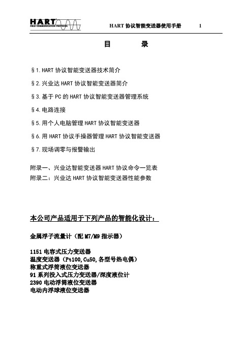
目录§1.HART协议智能变送器技术简介§2.兴业达HART协议智能变送器简介§3.基于PC的HART协议智能变送器管理系统§4.电路连接§5.用个人电脑管理HART协议智能变送器§6.用HART协议手操器管理HART协议智能变送器§7.现场调零与报警输出附录一、兴业达智能变送器HART协议命令一览表附录二:兴业达HART协议智能变送器性能参数本公司产品适用于下列产品的智能化设计:金属浮子流量计(配M7/M9指示器)1151电容式压力变送器温度变送器(Pt100,Cu50,各型号热电偶)称重式浮筒液位变送器91系列投入式压力变送器/深度液位计2390电动浮筒液位变送器电动内浮球液位变送器§1.HART协议智能变送器技术简介§1.1 工业自动化行业的大趋势---现场总线现场总线就是数字通讯一直延伸到现场仪表,使变送器、调节阀、记录仪、显示器、PLC及其它自动化设备等可通过一条总线进行双向多信息数字通讯,从而取代目前使用的4~20mA单变量单向模拟传输方式。
现场总线技术是在市场对现场仪表智能化以及全数字控制系统的需求驱动下产生的。
从技术的角度看,则是计算机技术、网络技术和控制技术发展的必然产物。
现场总线的关键标志是它能支持双向、多变量、总线式的全数字通信。
现场总线技术的出现,必将冲击现有过程控制系统的技术知识、设计方法、安装调试方法、人员培训以及产品市场的格局。
为了在这次变革中不至于被抛在后面,不同国家、不同厂商纷纷组成集团,发表各自的现场总线标准,以图率先占领市场。
比较主要的现场总线标准有Profitbus、CAN、Lonworks、SP50、ISPFIP和HART等,但由于受各自利益驱动和市场竞争,现场总线国际标准的制定进展缓慢。
§1.2 HART协议的发展虽然现场总线发展迅速,但由于4~20mA信号制的模拟设备还在大量使用中,因此从4~20mADC信号转变为现场总线全数字通讯并非一蹴而就,预计这一转变需要几十年时间。

hart协议单位代码表-中英对照HART(Highway Addressable Remote Transducer)协议是一种数字通信协议,用于工业自动化领域中的仪器仪表通信。
HART协议单位代码表用于标识和识别各种传感器、控制器和其他设备。
HART协议单位代码表包含了大量的单位代码,用于描述不同类型的测量参数和物理量。
下面是HART协议单位代码表的中英对照:1.时间单位- 1:秒(s)- 2:毫秒(ms)- 3:微秒(μs)- 4:纳秒(ns)2.电气单位- 10:伏特(V)- 11:安培(A)- 12:欧姆(Ω)- 13:毫安(mA)- 14:千伏特(kV)- 15:千欧姆(kΩ)- 16:焦耳(J)- 17:瓦特(W)- 18:千瓦特(kW)- 19:瓦时(Wh)- 20:安时(Ah)- 21:千安时(kAh)3.温度单位- 30:摄氏度(°C)- 31:华氏度(°F)- 32:开尔文(K)4.压力单位- 40:巴(Pa)- 41:毫巴(mbar)- 42:帕斯卡(Pa)- 43:千帕(kPa)- 44:兆帕(MPa)- 45:标况巴(bar)- 46:常压(atm)- 47:毫米水柱(mmH2O)- 48:英寸水柱(inH2O)- 49:英寸汞柱(inHg)- 50:kg/cm²- 51:磅力/平方英寸(psi)5.流量单位- 60:立方米/小时(m³/h)- 61:立方英尺/小时(ft³/h)- 62:加仑/小时(gph)- 63:毫升/分钟(ml/min)- 64:升/分钟(l/min)- 65:加仑/分钟(gpm)- 66:升/秒(l/s)- 67:加仑/秒(gps)6.重量单位- 70:千克(kg)- 71:克(g)- 72:毫克(mg)- 73:吨(t)- 74:磅(lb)- 75:盎司(oz)- 76:斤- 77:吨(US ton)- 78:吨(UK ton)7.距离单位- 80:米(m)- 81:毫米(mm)- 82:英寸(in)- 83:英尺(ft)- 84:码(yd)- 85:公里(km)- 86:英里(mi)- 87:海里(nmi)8.液位单位- 90:米(m)- 91:毫米(mm)- 92:英寸(in)- 93:英尺(ft)- 94:码(yd)- 95:公里(km)- 96:英里(mi)- 97:海里(nmi)9.震动单位- 100:米/秒²(m/s²)- 101:加速度单位(g)- 102:振动单位(in/s)- 103:振幅单位(mil)- 104:压力单位(psi)- 105:角度单位(°)- 106:频率单位(Hz)10.湿度单位- 110:百分比(%RH)- 111:绝对湿度(g/m³)- 112:湿球温度(°C)- 113:露点温度(°C)以上仅是HART协议单位代码表的一部分,还有更多单位代码用于描述其他类型的物理量和测量参数。
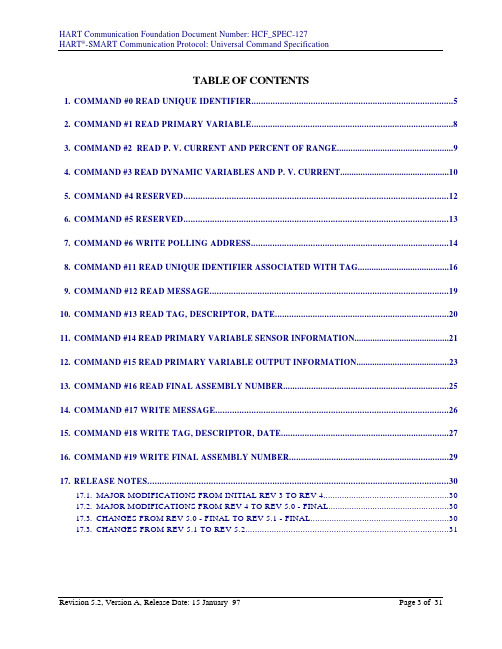
TABLE OF CONTENTSMAND #0 READ UNIQUE IDENTIFIER (5)MAND #1 READ PRIMARY VARIABLE (8)MAND #2 READ P. V. CURRENT AND PERCENT OF RANGE (9)MAND #3 READ DYNAMIC VARIABLES AND P. V. CURRENT (10)MAND #4 RESERVED (12)MAND #5 RESERVED (13)MAND #6 WRITE POLLING ADDRESS (14)MAND #11 READ UNIQUE IDENTIFIER ASSOCIATED WITH TAG (16)MAND #12 READ MESSAGE (19)MAND #13 READ TAG, DESCRIPTOR, DATE (20)MAND #14 READ PRIMARY VARIABLE SENSOR INFORMATION (21)MAND #15 READ PRIMARY VARIABLE OUTPUT INFORMATION (23)MAND #16 READ FINAL ASSEMBLY NUMBER (25)MAND #17 WRITE MESSAGE (26)MAND #18 WRITE TAG, DESCRIPTOR, DATE (27)MAND #19 WRITE FINAL ASSEMBLY NUMBER (29)17.RELEASE NOTES (30)17.1.MAJOR MODIFICATIONS FROM INITIAL REV 3 TO REV 4 (30)17.2.MAJOR MODIFICATIONS FROM REV 4 TO REV 5.0 - FINAL (30)17.3.CHANGES FROM REV 5.0 - FINAL TO REV 5.1 - FINAL (30)17.3.CHANGES FROM REV 5.1 TO REV 5.2 (31)MAND #0 READ UNIQUE IDENTIFIERThis is a Data Link Layer Management Command.Returns the Expanded Device Type Code, Revision Levels, and Device Identification Number. This command is implemented by a Field Device in both Short and Extended Data Link Layer Frame Formats.The Device Type Code will always be returned in the expanded three byte format. ("254", Manufacturer Identification Code, Manufacturer's Device Type Code)The combination of Manufacturer Identification Code, Manufacturer's Device Type Code, and Device Identification Code make up the Unique Identifier required for the Extended Frame Format of the Data Link Layer.REQUEST DATA BYTESNONERESPONSE DATA BYTESDATA BYTES#0"254"#1MFRID#2MFR'SDEVICETYPE#3 NUMBER RQUEST PREAM#4 UNIV CMD REV #5TRANSSPECREV#6SOFTREV#7HARDREV#8 FLAGS#9 DEVICE ID NUMBER MSB #10#11DEVICEIDNUMBERLSBData Byte #0Device Type Code for Expansion; "254", 8-bit unsignedintegerData Byte #1Manufacturer Identification Code, 8-bit unsigned integer,Refer to Table VIII; Manufacturer Identification CodesData Byte #2Manufacturer's Device Type Code, 8-bit unsigned integer,Refer to the Device Type Codes Table of the manufacturer,Rosemount Device Type Codes are contained in Table I;Rosemount Device Type CodesData Byte #3Number of Preambles required for the Request messagefrom the Master to the Slave, Includes those contained in theMessage Detect; 8-bit unsigned integerData Byte #4Revision Level of the Universal Command Documentimplemented by this device, 8-bit unsigned integer, Levels254 and 255 are Reserved.Data Byte #5Revision Level of the Transmitter-Specific Documentimplemented by this device, 8-bit unsigned integer, Levels254 and 255 are ReservedData Byte #6Software Revision Level of this device, 8-bit unsignedinteger, Levels 254 and 255 are ReservedData Byte #7Hardware Revision Level of the electronics in this device;does not necessarily trace component changes, 8-bit unsignedinteger in the format of xxxxx.yyyBx - Device Hardware Revision Level, 5-bit unsigned integer,Level 15 is Reservedy - Physical Signaling Code, 3-bit unsigned integer, Refer toTable X; Physical Signaling CodesData Byte #8Flags, 8-bit unsigned integer, Refer to Table XI; FlagAssignmentsData Byte #9 - #11Device Identification Number, 24-bit unsigned integerCOMMAND-SPECIFIC RESPONSE CODES0 No Command-Specific Errors1 - 5Undefined6Transmitter-Specific Command Error7 - 15Undefined16Access Restricted17 - 127UndefinedMAND #1 READ PRIMARY VARIABLERead the Primary Variable. The Primary Variable is returned in floating point format. REQUEST DATA BYTESNONERESPONSE DATA BYTESDATA BYTES#0PVUNITS #1PVMSB#3#2#4PVLSBData Byte #0Primary Variable Units Code, 8-bit unsigned integer,Refer to Table II; Unit CodesData Byte #1 - #4Primary Variable, IEEE 754COMMAND-SPECIFIC RESPONSE CODES0No Command-Specific Errors1 - 5Undefined6Transmitter-Specific Command Error7Undefined8Warning: Update Failure9 - 15Undefined16Access Restricted17 - 127UndefinedMAND #2 READ P. V. CURRENT AND PERCENT OF RANGE Reads the Primary Variable as Current and a percent of the Primary Variable Range. The Primary Variable Current always matches the Analog Output current of the device including alarm conditions and set values. Percent of Range always follows the Primary Variable, even if the Primary Variable Current is in an alarm condition or set to a value. Also, the Percent of Range is not limited to values between 0% and 100%, but tracks the Primary Variable beyond the Range Values to the Sensor Limits when they are defined.REQUEST DATA BYTESNONERESPONSE DATA BYTESDATA BYTES#0PVCURRMSB #1#2#3PVCURRLSB#4PV PER RANGE MSB #5#6#7PVPERRANGELSBData Byte #0 - #3Primary Variable Current, IEEE 754, Units ofmilliamperesData Byte #4 - #7Primary Variable Percent of Range, IEEE 754, Units ofpercentCOMMAND-SPECIFIC RESPONSE CODES0No Command-Specific Errors1 - 5Undefined6Transmitter-Specific Command Error7Undefined8Warning: Update Failure9 - 15Undefined16Access Restricted17 - 127UndefinedMAND #3 READ DYNAMIC VARIABLES AND P. V. CURRENTRead the Primary Variable Current and up to four predefined Dynamic Variables. The Primary Variable Current always matches the Analog Output current of the device including alarm conditions and set values. The Secondary, Tertiary, and 4th Variables are defined by each device type (e.g. the Secondary Variable is the Sensor Temperature for the 3051 Pressure Transmitter).REQUEST DATA BYTESNONERESPONSE DATA BYTESDATA BYTES#0PVCURRMSB #1#2#3PVCURRLSB#4PV UNITS #5PVMSB#6#7#8PVLSB#9SV UNITS #10SVMSB#11#12#13SVLSB#14 TV UNITS #15TVMSB#16#17#18TVLSB#194th V UNITS #204th VMSB#21#22#234th VLSBNOTE:Data string truncates after last variable supported by each device type.Data Byte #0 - #3Primary Variable Current, IEEE 754, Units ofmilliamperesData Byte #4Primary Variable Units Code, 8-bit unsigned integer,Refer to Table II; Unit CodesData Byte #5 - #8Primary Variable, IEEE 754Data Byte #9Secondary Variable Units Code, 8-bit unsigned integer,Refer to Table II; Unit CodesData Byte #10 - #13Secondary Variable, IEEE 754Data Byte #14Tertiary Variable Units Code, 8-bit unsigned integer,Refer to Table II; Unit CodesData Byte #15 - #18Tertiary Variable, IEEE 754Data Byte #194th Variable Units Code, 8-bit unsigned integer, Refer toTable II; Unit CodesData Byte #20 - #234th Variable, IEEE 754COMMAND-SPECIFIC RESPONSE CODES0No Command-Specific Errors1 - 5Undefined6Transmitter-Specific Command Error7Undefined8Warning: Update Failure9 - 15Undefined16Access Restricted17 - 127UndefinedRevisions 3 and 4 of this document included this command.Revisions 3 and 4 of this document included this command.MAND #6 WRITE POLLING ADDRESSThis is a Data Link Layer Management Command.This command writes the Polling Address to the field device. The address is used to control the Primary Variable Analog Output and provide a means of device identification in Multidrop installations.The Primary Variable Analog Output responds to the applied process only when the Polling Address of the device is set to 0. When the address assigned to a device is in the range from 1 through 15, the Analog Output is Not Active and does not respond to the applied process. While the Analog Output is Not Active, the Analog Output is set to its minimum; the Transmitter Status Bit #3, Primary Variable Analog Output Fixed, is set; and the Upscale/Downscale Alarm is disabled. If the Polling Address is changed back to 0, the Primary Variable Analog Output will gain become Active and respond to the applied process.REQUEST DATA BYTESDATA BYTES#0POLLADDRData Byte #0Polling Address of Device, 8-bit unsigned integer0Analog Output Active1 - 15Analog Output Not Active16 - 255InvalidRESPONSE DATA BYTESDATA BYTES#0POLLADDRData Byte #0Polling Address of Device, 8-bit unsigned integer0Analog Output Active1 - 15Analog Output Not Active16 - 255InvalidCOMMAND-SPECIFIC RESPONSE CODES0No Command-Specific Errors1Undefined2Invalid Selection3 - 4Undefined5Too Few Data Bytes Received6Transmitter-Specific Command Error7In Write Protect Mode8 - 15Undefined16Access Restricted17 - 127UndefinedMAND #11 READ UNIQUE IDENTIFIER ASSOCIATED WITH TAGThis is a Data Link Layer Management Command.This command returns the Expanded Device Type Code, Revision Levels, and Device Identification Number of a device containing the devices Tag. It will be executed when either the devices Extended Address or the Broadcast Address is received. The Extended Address in the Response message is the same as the request.This command is unique in that no response is made unless the Tag matches that of the device.The Device Type Code returned in the Response Data Bytes will always be returned in the expanded three byte format. ("254", Manufacturer Identification Code, Manufacturer's Device Type Code)REQUEST DATA BYTESDATA BYTES#0TAGBYTE #0…#5TAGBYTE #5Data Byte #0 - #5Tag, Packed-ASCII RESPONSE DATA BYTESDATA BYTES#0“254”#1MFRID#2MFR’SDEVICETYPE#3 NUMBER RQUEST PREAM#4 UNIV CMD REV #5TRANSSPECREV#6SOFTREV#7HARDREV#8 FLAGS#9 DEVICE ID NUMBER MSB #10#11DEVICEIDNUMBERLSBData Byte #0Device Type Code for Expansion; "254", 8-bit unsignedintegerData Byte #1Manufacturer Identification Code, 8-bit unsigned integer,Refer to Table VIII; Manufacturer Identification Codes Data Byte #2Manufacturer's Device Type Code, 8-bit unsigned integer,Refer to the Device Type Codes Table of themanufacturer, Rosemount Device Type Codes arecontained in Table I; Rosemount Device Type Codes Data Byte #3Number of Preambles required for the Request messagefrom the Master to the Slave, Includes those contained inthe Message Detect; 8-bit unsigned integerData Byte #4Revision Level of the Universal Command Documentimplemented by this device, 8-bit unsigned integer,Levels 254 and 255 are ReservedData Byte #5Revision Level of the Transmitter-Specific Documentimplemented by this device, 8-bit unsigned integer,Levels 254 and 255 are ReservedData Byte #6Software Revision Level of this device, 8-bit unsignedinteger, Levels 254 and 255 are ReservedData Byte #7Hardware Revision Level of the electronics in this device;does not necessarily trace component changes, 8-bitunsigned integer in the format of xxxxx.yyyBx - Device Hardware Revision Level, 5-bit unsignedinteger, Level 15 is Reservedy - Physical Signaling Code, 3-bit unsigned integer, Referto Table X; Physical Signaling CodesData Byte #8Flags, 8-bit unsigned integer, Refer to Table XI; FlagAssignmentsData Byte #9 - #11Device Identification Number, 24-bit unsigned integerCOMMAND-SPECIFIC RESPONSE CODES0No Command-Specific Errors1 - 4Undefined5Too Few Data Bytes Received [See Note]6Transmitter-Specific Command Error7 - 15Undefined16Access Restricted17 - 127UndefinedNOTE:This Response Code was placed here in error and it will not be returned in proper implementations of this command.MAND #12 READ MESSAGE Reads the Message contained within the device. REQUEST DATA BYTESNONERESPONSE DATA BYTESDATA BYTES#0MESSAGEBYTE #0…#5MESSAGEBYTE #23Data Byte #0 - #23Message, Packed-ASCII COMMAND-SPECIFIC RESPONSE CODES0No Command-Specific Errors1 - 5Undefined6Transmitter-Specific Command Error7 - 15Undefined16Access Restricted17 - 127UndefinedMAND #13 READ TAG, DESCRIPTOR, DATE Read the Tag, Descriptor, and Date contained within the device. REQUEST DATA BYTESNONERESPONSE DATA BYTESDATA BYTES#0TAGBYTE #0…#5TAGBYTE #5#6 DESCR BYTE #0…#17DESCRBYTE #11#18 DATE #19DATE#20DATEData Byte #0 - #5Tag, Packed-ASCIIData Byte #6 - #17Descriptor, Packed-ASCIIData Byte #18 - #20Date, 8-bit unsigned integers, Respectively day, month,year-1900NOTE: Those parameters not applicable to a device will be set to "250", Not Used. COMMAND-SPECIFIC RESPONSE CODES0No Command-Specific Errors1 - 5Undefined6Transmitter-Specific Command Error7 - 15Undefined16Access Restricted17 - 127UndefinedMAND #14 READ PRIMARY VARIABLE SENSORINFORMATIONReads the Primary Variable Sensor Serial Number, Primary Variable Sensor Limits/Minimum Span Units Code, Primary Variable Upper Sensor Limit, Primary Variable Lower Sensor Limit, and Primary Variable Minimum Span for the sensor.The Primary Variable Sensor Limits and Minimum Span Units will be the same as the Primary Variable Units.REQUEST DATA BYTESNONERESPONSE DATA BYTESDATA BYTES#0PVSENSORSERIALNUMBERMSB #1#2PVSENSORSERIALNUMBERLSB#3PV SENSOR LIMITS/ MIN SPAN UNITS #4PVUPPERSENSORLIMITMSB#5#6#7PVUPPERSENSORLIMITLSB#8PV LOWER SENSOR LIMIT MSB #9#10#11PVLOWERSENSORLIMITLSB#12 PV MIN SPAN MSB #13#14#15PVMINSPANLSBData Byte #0 - #2Primary Variable Sensor Serial Number, 24-bit unsignedintegerData Byte #3Primary Variable Sensor Limits and Minimum SpanUnits Code, 8-bit unsigned integer, Refer to Table II; UnitCodesData Byte #4 - #7Primary Variable Upper Sensor Limit, IEEE 754Data Byte #8 - #11Primary Variable Lower Sensor Limit, IEEE 754Data Byte #12 - #15Primary Variable Minimum Span, IEEE 754NOTE:When the Sensor Serial Number is not applicable to the device or Primary Variable, it will be set to "0". The other parameters will be set to 7F A0 00 00,Not-a-Number, or "250", Not Used, when they are not applicable.COMMAND-SPECIFIC RESPONSE CODES0No Command-Specific Errors1 - 5Undefined6Transmitter-Specific Command Error7 - 15Undefined16Access Restricted17 - 127UndefinedMAND #15 READ PRIMARY VARIABLE OUTPUTINFORMATIONReads the Primary Variable Alarm Selection Code, Primary Variable Transfer Function Code, Primary Variable Range Values Units Code, Primary Variable Upper Range Value, Primary Variable Lower Range Value, Primary Variable Damping Value, Write Protect Code, and Private Label Distributor Code associated with the device or the Primary Variable.The Primary Variable Damping Value is applied to both the Primary Variable Analog Output and the digital Primary Variable.REQUEST DATA BYTESNONERESPONSE DATA BYTESDATA BYTES#0PVALARMSELECTCODE #1PVXFERFNCTCODE#2PVRANGEVALUESUNITSCODES#3PV UPPER RANGE VALUE MSB #4#5#6PVUPPERRANGEVALUELSB#7PV LOWER RANGE VALUE MSB #8#9#10PVLOWERRANGEVALUELSB#11PV DAMP VALUE MSB #12#13#14PVDAMPVALUELSB#15 WRITE PROT CODE #16 PVT LABEL DIST CODEData Byte #0Primary Variable Alarm Selection Code, 8-bit unsignedinteger, Refer to Table VI; Alarm Selection CodesData Byte #1Primary Variable Transfer Function Code, 8-bit unsignedinteger, Refer to Table III; Transfer Function Codes Data Byte #2Primary Variable Upper and Lower Range Values UnitsCode, 8-bit unsigned integer, Refer to Table II; UnitCodesData Byte #3 - #6Primary Variable Upper Range Value, IEEE 754Data Byte #7 - #10Primary Variable Lower Range Value, IEEE 754Data Byte #11 - #14Primary Variable Damping Value, IEEE 754, Units ofsecondsData Byte #15Write Protect Code, 8-bit unsigned integer, Refer toTable VII; Write Protect CodesData Byte #16Private Label Distributor Code, 8-bit unsigned integer,Refer to Table VIII; Manufacturer Identification Codes NOTE:The Write Protect Code defaults to "251", None, (or "250", Not Used, for earlier model devices) when this feature has not been implemented by a device. ThePrivate Label Distributor Code defaults to the primary manufacturer of the device(or "250", Not Used, for earlier model devices). The other parameters notapplicable to a device or Primary Variable will be set to 7F A0 00 00, Not-a-Number, or "250", Not Used.COMMAND-SPECIFIC RESPONSE CODES0No Command-Specific Errors1 - 5Undefined6Transmitter-Specific Command Error7 - 15Undefined16Access Restricted17 - 127UndefinedMAND #16 READ FINAL ASSEMBLY NUMBER Read the Final Assembly Number associated with the device. REQUEST DATA BYTESNONERESPONSE DATA BYTESDATA BYTES#0FINALASSEMBLYNUMBERMSB #1#2FINALASSEMBLYNUMBERLSBData Byte #0 - #2Final Assembly Number, 24-bit unsigned integer NOTE:All data in the Response Packet is read from data memory. COMMAND-SPECIFIC RESPONSE CODES0No Command-Specific Errors1 - 5Undefined6Transmitter-Specific Command Error7 - 15Undefined16Access Restricted17 - 127UndefinedMAND #17 WRITE MESSAGE Write the Message into the device.REQUEST DATA BYTESDATA BYTES#0MESSAGEBYTE #0…#23MESSAGEBYTE #23Data Byte #0 - #23Message, Packed-ASCII RESPONSE DATA BYTESDATA BYTES#0MESSAGEBYTE #0…#23MESSAGEBYTE #23Data Byte #0 - #23Message, Packed-ASCII NOTE:All data in the Response Packet is read from data memory. COMMAND-SPECIFIC RESPONSE CODES0No Command-Specific Errors1 - 4Undefined5Too Few Data Bytes Received6Transmitter-Specific Command Error7In Write Protect Mode8 - 15Undefined16Access Restricted17 - 127UndefinedMAND #18 WRITE TAG, DESCRIPTOR, DATE Write the Tag, Descriptor, and Date into the device.REQUEST DATA BYTESDATA BYTES#0TAGBYTE #0…#5TAGBYTE #5#6 DESCR BYTE #0…#17DESCRBYTE #11#18 DATE #19DATE#20DATEData Byte #0 - #5Tag, Packed-ASCIIData Byte #6 - #17Descriptor, Packed-ASCIIData Byte #18 - #20Date, 8-bit unsigned integers, Respectively day', month,year-l900RESPONSE DATA BYTESDATA BYTES#0TAGBYTE #0…#5TAGBYTE #5#6 DESCR BYTE #0…#17DESCRBYTE #11#18 DATE #19DATE#20DATEData Byte #0 - #5Tag, Packed-ASCIIData Byte #6 - #17Descriptor, Packed-ASCIIData Byte #18 - #20Date, 8-bit unsigned integers, Respectively day, month,year-l900NOTE:All data in the Response Packet is read from data memory.NOTE:Those parameters not applicable to a device will be set to "250", Not Used.COMMAND-SPECIFIC RESPONSE CODES0No Command-Specific Errors1 - 4Undefined5Too Few Data Bytes Received6Transmitter-Specific Command Error7In Write Protect Mode8 - 15Undefined16Access Restricted17 - 127UndefinedMAND #19 WRITE FINAL ASSEMBLY NUMBER Write Final Assembly Number into the device.REQUEST DATA BYTESDATA BYTES#0FINALASSEMBLYNUMBERMSB #1#2FINALASSEMBLYNUMBERLSBData Byte #0 - #2Final Assembly Number, 24-bit unsigned integer RESPONSE DATA BYTESDATA BYTES#0FINALASSEMBLYNUMBERMSB #1#2FINALASSEMBLYNUMBERLSBData Byte #0 - #2Final Assembly Number, 24-bit unsigned integer NOTE:All data in the Response Packet is read from data memory. COMMAND-SPECIFIC RESPONSE CODES0No Command-Specific Errors1 - 4Undefined5Too Few Data Bytes Received6Transmitter-Specific Command Error7In Write Protect Mode8 - 15Undefined16Access Restricted17 - 127Undefined17.RELEASE NOTES17.1.Major Modifications from Initial Rev 3 to Rev 4-This Revision incorporates the Write Protect Mode.-This Revision adds the Private Labeling capability.(Refer to document Revision 3, D8700028, and Revision 4, D8900037 for detailedinformation.)17.2.Major Modifications from Rev 4 to Rev 5.0 - Final-A decimal point and integer has been added to the HART document revision numberingsystem. This minor revision number is incremented each time corrections or changes are made to a previously approved document.-Changed Rosemount Document Number from D8700028; Revision C to D8900038;Revision A. A different Rosemount Document Number is assigned to each majorHART Document Revision Number.-Increased the maximum Command-Specific Response Code number from 15 to 127 forall commands.-This revision adds the Extended Frame Format and creates a separate command for eachBlock of Command #4 and #5.-Added Command #11 - 1917.3Changes from Rev 5.0 - Final to Rev 5.1 - Final-This revision includes modifications for devices with Multiple Analog Outputs andAnalog Outputs other than Current.-Summarized Release Notes from Rev 4 to Rev 5.0 - Final.Page Line Change TextTP4Replace"5.0" by "5.1"TP6Replace"8 February 1990" by "18 October 1990"TP7Replace"12 February 1990" by "18 October 1990"TP8Replace"A" by "8"52Insert"P. V."55Insert"Primary Variable"58Insert"Primary Variable"520Insert"PV PV"525Insert"PV PV"530Replace"Analog Output" by "Primary Variable"534Insert"Primary Variable"535Replace"IEEE 754," by "IEEE 754,"62Delete"ALL"62Insert"P. V."64Insert"Primary Variable"65Insert"Primary Variable"618Insert"PV PV"72Replace"Analog Output" by "Primary Variable"107Insert"Primary Variable"1010Insert"Primary Variable"1014Replace"current" by "Analog Output"1015Replace"4 milliamperes;" by "its minimum"1016Replace"#4," by "#3, Primary Variable Analog"1017Delete"Current"1018Insert"Primary Variable"146Insert"[See Note]"Page Line Change Text1413Insert"Note: This Response Code uas placed here in..."174Insert"Primary Variable"174Insert"Primary Variable"175Insert"Primary Variable"176Insert"Primary Variable"177Insert"Primary Variable"177Insert"sensor."179Replace"sensor associated..." by "The"179Delete"Variable."179Replace"The" by "Variable"1720Insert"PV PV"1727Insert"PV PV PV"1735Insert"PV PV"1742Insert"PV PV"182Insert"Primary Variable"185Insert"Data Byte #3 Primary Variable Sensor Limits..."1821Delete"Data Byte #4 - #7 Upper Sensor Limit, IEEE..."1825Insert"Primary Variable"192Insert"PRIMARY VARIABLE"194Insert"Primary Variable"194Insert"Primary Variable"195Replace"Variable/Range" by "Variable Range Values"196Insert"Primary Variable"197Insert"Primary Variable"197Insert"Primary Variable"1911Insert"Primary Variable"1911Insert"Primary Variable"1921Insert"PV PV PV"1922Replace"PV/" by "RANGE"1923Replace"RANGE" by "VALUES"1928Insert"PV PV"1935Insert"PV PV"1942Insert"PV PV"202Insert"Primary Variable"206Delete"Data Byte #1 Transfer Function Code, 8-bit..."2019Move"Data Byte" from page 18 line 172019Replace"#3 Sensor Limits and..." by "#1 Primary..."2022Replace"II; Unit" by "III; Transfer Function"2025Insert"Data Byte #2 Primary Variable Upper and Lover..."2035Insert"Primary Variable"2410Replace"16 Transmitter-..." by "16 Access Restricted"17.3Changes from Rev 5.1 to Rev 5.2The document was translated from a Multimate document to Microsoft Word. As a result of this translation the document format was altered. No other modifications were made to the document.®HARTFIELD COMMUNICATION PROTOCOLDocument Title: HART ® SMART CommunicationsProtocol, Universal CommandSpecificationDocument Revision: 5.2HART ® Communication Foundation DocumentNumber: HCF_SPEC-127Maintenance ControlDistribution ControlLocation of Original Master:Company: HART Communication FoundationAddress: 9390 Research Blvd., Suite I-350, Austin,TX, 78759, USALocation of Electronic Archive:Computer: PM7200Archive copy path: Archive:SPEC:127:5.2:ALocation of Copy Master:Company: HART Communication Foundation Address: 9390 Research Blvd., Suite I-350,Austin, TX, 78759, USADistribution Contact: Foundation DirectorApproval ControlCompany name / Persons title (Executive)Persons Name Persons Signature Date Signed HART ®Communication Foundation / Director Ron Helson On File 22an97Rosemount Inc. / Chairman Exec Comm Jim Cobb On File 22Jan97HART ® Communication Foundation / HCF StaffKeith KleinschmidtOn File22Jan97Version HistoryVersion a 15Jan97。

HART通信协议一、协议目的本协议旨在规范HART通信协议的标准格式,确保通信设备之间能够有效地进行数据传输和交互。
二、协议范围本协议适用于使用HART通信协议的各类设备,包括但不限于传感器、执行器、控制器等。
三、术语定义1. HART通信协议:Highway Addressable Remote Transducer Protocol的缩写,是一种数字通信协议,用于在4-20mA模拟信号中传输数字通信数据。
2. 主设备:指能够发送和接收HART通信协议数据的设备。
3. 从设备:指接收主设备发送的HART通信协议数据的设备。
4. HART命令:指在HART通信协议中用于发送和接收数据的特定命令。
四、通信规范1. 物理层规范a. HART通信协议使用4-20mA模拟信号进行通信。
b. 通信线路应符合相关标准,确保信号传输的稳定性和可靠性。
c. 通信线路长度应根据具体设备要求进行合理设置,以避免信号衰减和干扰。
2. 数据帧格式a. HART通信协议采用Master/Slave结构,数据传输通过主设备和从设备之间的交互完成。
b. 数据帧包括Preambles、Start Delimiter、Address Byte、Command Byte、Data Byte、Checksum等字段。
c. Preambles字段用于同步主从设备的通信时钟。
d. Start Delimiter字段标识数据帧的起始。
e. Address Byte字段用于指定从设备的地址。
f. Command Byte字段用于指定HART命令。
g. Data Byte字段用于传输数据。
h. Checksum字段用于校验数据的完整性。
3. HART命令规范a. HART通信协议定义了一系列标准的HART命令,用于实现不同的功能和操作。
b. HART命令包括但不限于读取、写入设备参数、配置设备、诊断设备等。
c. 每个HART命令都有特定的命令字节和数据格式,发送方和接收方必须按照规定的格式进行数据交互。

HART 指南HART 指南1、简介1.1 目的1.2 范围1.3 定义2、HART 概述2.1 HART 的起源和发展2.2 HART 的工作原理2.3 HART 的特点和优势3、HART 设备3.1 HART 设备的分类3.2 HART 设备的组成和功能3.3 HART 设备的安装和配置3.4 HART 设备的维护和故障排除4、HART 通信协议4.1 HART 通信协议的基本原理 4.2 HART 通信协议的消息格式 4.3 HART 通信协议的通信模式4.4 HART 通信协议的应用场景5、HART 网络拓扑5.1 HART 网络的组成和结构5.2 HART 网络的配置和管理5.3 HART 网络的故障排除和维护6、HART 应用案例6.1 HART 在工业领域的应用6.2 HART 在能源领域的应用6.3 HART 在环境监测领域的应用7、HART 安全性7.1 HART 安全性的重要性7.2 HART 安全性的威胁和风险7.3 HART 安全性的保护措施8、HART 标准和规范8.1 HART 标准的制定和评审8.2 HART 标准的更新和发布8.3 HART 标准的遵循和合规性9、HART 资源与支持9.1 HART 相关的资料和文档9.2 HART 的技术支持和培训9.3 HART 用户组织和会议10、HART 与其他通信协议的比较10.1 HART 与 Modbus 的比较10.2 HART 与 Foundation Fieldbus 的比较 10.3 HART 与 Profibus 的比较附件:本文档附带的附件包括:- HART 设备安装手册- HART 通信协议规范- HART 网络配置示例法律名词及注释:1、HART:Highway Addressable Remote Transducer2、HART 通信协议:一种用于工业自动化系统的数字通信协议,可通过4-20mA电流回路传送数字和模拟信号。
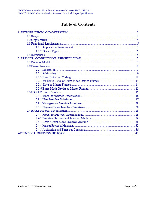
Table of Contents1. INTRODUCTION AND OVERVIEW (5)1.1 Scope (5)1.2 Organization (5)1.3 Functional Requirements (5)1.3.1 Application Environment (5)1.3.2 Device Types (6)1.4 References (6)2. SERVICE AND PROTOCOL SPECIFICATIONS (7)2.1 Protocol Model (7)2.2 Frame Formats (8)2.2.1 Preambles (9)2.2.2 Addressing (9)2.2.3 Error Detection Coding (12)2.2.4 Master to Slave or Burst-Mode Device Frames (13)2.2.5 Slave to Master Frames (14)2.2.6 Burst-Mode Device to Master Frames (15)2.3 HART Protocol Services (16)2.3.1 Model for Service Specifications (16)2.3.2 User Interface Primitives (17)2.3.3 Management Interface Primitives (23)2.3.4 Physical Layer Interface Primitives (26)2.4 HART Protocol Specification (28)2.4.1 Model for Protocol Specifications (28)2.4.2 Primitive Receive and Transmit Machines: (29)2.4.3 Slave / Burst-Mode Protocol Machine (31)2.4.4 Master Protocol Machine (32)2.4.5 Arbitration and Time-out Constants (36)APPENDIX A: REVISION HISTORY (40)FiguresFigure 1 HART Protocol Model (8)Figure 2 HART Frame Format (9)Figure 3 Long Frame Address (10)Figure 4 Short Frame Address (12)Figure 5 HART Error Detection Scheme (12)Figure 6 The Delimiter Character (14)Figure 7 Model for Protocol Service Specifications (17)Figure 8 Transmit Service Sequence (19)Figure 9 Transfer Service Sequence (21)Figure 10 Cyclic Service Sequence (23)Figure 11 Remote/ Local Management Sequence (24)Figure 12 Physical Layer Primitive Sequences (26)Figure 13 Finite State Machine Model (29)Figure 14 RCV_MSG Receive State Machine (30)Figure 15 XMIT_MSG Transmit State Machine (31)Figure 16 Slave/ Burst-Mode Device State Machine (32)Figure 17 Master State Machine (35)Figure 18 The Timer Model (37)Figure 19 RT2 Timing (38)Figure 20 RT1 Timing (39)1. INTRODUCTION AND OVERVIEWThis specification defines the Data Link Layer protocol to be used by devices claiming conformance to the HART® specification. It describes the communication protocol in an implementation independent form so that it may be translated for any processor and any implementation language. 1.1 ScopeThis document describes the rules used by HART products to communicate digital information over a physical link. It describes the services made available to devices using the protocol and the services that must be provided to an implementation of this protocol specification by underlying protocol layers.1.2 OrganizationThis specification is organized so as to provide an overview of functional requirements addressed by the protocols, followed by a layer by layer description of protocol interfaces and functionality following the philosophy behind the ISO/OSI model.1.3 Functional RequirementsThis section outlines those communication requirements between devices that are addressed by the protocol specification.1.3.1 Application EnvironmentThe protocol is intended to provide a reliable, transaction oriented communication path to and from slave devices such as field instruments, for digital data transfer. Communications is over twisted pair that may be simultaneously carrying 4-20mA signaling. The protocol will correct for errors due to noise on the communication links by using error detecting information and an Automatic Repeat Request (ARQ) protocol to request the re-transmission of data blocks that may be corrupted by line noise or other disturbances.If poll (short form) addresses are used, up to 15 slave devices may be multi-dropped on a singlecommunication link (see Section 2.2.2.2). If unique (long form) addresses are used, the number of multi-dropped devices is essentially unlimited, and is determined based on the applications required rate of scan of the devices on the communication link (see Section 2.2.2.1).The protocol will also arbitrate access to the field instrument between secondary master devices such as a handheld terminal and primary master devices such as a control system. The protocol gives equal access to the communication channel to both kinds of masters when they are being simultaneously used. The protocol will not arbitrate between two secondary or two primary masters trying to talk on the same link.To support the regular transfer of information from slave device to master device, the protocol supports a mode of operation in which slave devices periodically broadcast information onto the communication link. A slave device is said to be in "burst mode" when it is providing a synchronouscyclic broadcasting of data, without continuous polling by a master device. No matter how manyslave devices are on a communication link, only one may be in burst mode.Information transfer between devices on the communication link is through a defined message format. The entire message is protected by a single parity check product code (sometimes also known as vertical and longitudinal parity checking). Message framing is through a combination of a start of frame delimiter and a message length field.The protocol provides services for device identification, segmented data transfer, and communication configuration. Other HART protocol documents cover the interpretation of data transferred by this protocol between various slave devices and the primary or secondary masters.1.3.2 Device TypesThe communications protocol recognizes three distinct device types among entities capable of using this protocol. The most general and basic type is the slave device. This is a device which accepts orprovides a digital message carrying measurement or other data, but only when specifically requested, i.e. this device always functions as a slave in a master/slave relationship.The second device type recognized by the protocol is the burst mode device. This is a device which provides a digital response carrying measurement or other data, at regular intervals, without the data being specifically requested, i.e. this device normally functions as an independently broadcasting device. A burst mode device is defined to be a slave mode device with burst mode capability (hence the use of the word "mode" in describing the device type). When such a mode is enabled, the device is said to "be in burst mode".The third device type recognized by the protocol is a master device. A master device is responsible for initiating, controlling and terminating transactions with a slave device or a burst mode device. A distinction is made between master devices into primary master devices and secondary master devices in order to allow the simultaneous use of two master devices on a HART communication link. The same protocol rules are followed by a primary master device and a secondary master device except for customizing time-outs that differentiate between them.1.4 ReferencesThis Specification refers to the following documents that are part of the HART Communications Specification set:1. HART®-SMART Communications Protocol, FSK Physical Layer Specification.HCF_SPEC-53. HART Communication Foundation.2. HART®-SMART Communications Protocol, Command Summary Specification.HCF_SPEC-99. HART Communication Foundation.3. HART®-SMART Communications Protocol, Universal Command Specification.HCF_SPEC-127. HART Communication Foundation.4. HART®-SMART Communications Protocol, Common Practice CommandSpecification. HCF_SPEC-151. HART Communication Foundation.5. HART®-SMART Communications Protocol, Appendix 1 - Command SpecificResponse Code Definitions. HCF_SPEC-307. HART Communication Foundation. In addition, the documents:Data Link Layer Slave, Structured Analysis. HCF_LIT-8. HART CommunicationFoundation.Data Link Layer Master, Structured Analysis. HCF_LIT-9. HART CommunicationFoundation.HART Slave Library Software Design. HCF_LIT-11. HART CommunicationFoundation.are generally accepted reference Data Link Layer implementations. However, at this point in time, they have not been approved as a substitute for the HART specifications.2. SERVICE AND PROTOCOL SPECIFICATIONSThe first parts (2.1-2.3) of this section define the services provided to the user by the protocol and the interface between the user and the protocol implementation. They define what information must be supplied to the protocol for it to successfully transmit or receive data. They also specify in what order this data must be supplied and when responses can be expected. The last section (2.4) provides a detailed description of the protocol itself.2.1 Protocol ModelFigure 1 is a conceptual model of a HART protocol implementation. It is intended as a frame of reference rather than as a description of an actual implementation. The purpose is to show the relationships between the various services, interfaces, and protocol components that are described in detail in later sections. As can be seen from the figure, the model distinguishes between five components. Two of these, the user/protocol interface and the protocol/physical layer interface are descriptions of services that are provided to or required from adjacent protocol "layers". The other three components make up the protocol specification itself. This is broken up in terms of three corresponding state machines. The receive and transmit machines describe handling of message transmission and reception, while the main state machine uses invocations of these to implement the rest of the protocol.The interface between the various components of the protocol is specified in terms of service primitives. The specification of a service consists of two parts, the first of which is a description of the primitive. This is a pseudo higher level language module / procedure definition describingparameters used by the service. The second is a sequence diagram which shows the order of events at the interface.Protocol specifications themselves are formulated in terms of a state transition diagram. This notation allows an unambiguous description of the action of the protocol. An outline of this protocol description technique is provided later.Figure 1 HART Protocol Model2.2 Frame FormatsAll data transferred between entities involved in the protocol is transferred in the form of frames. A frame is an encapsulation of user data in control and addressing information. Protocol implementations shall not make any interpretation of user data (labeled as "data" in Figure 2). This means that frame recognition is disabled from the beginning of the user data field until the frame is complete as determined by a (correct) byte-count or by the physical layer signaling the end of a message (e.g. through absence of carrier detect).A frame is delimited by the combination of characters called preambles, a unique "start of frame" character (Delimiter) which identifies the frame's beginning, and by a Byte Count field which determines where the frame ends. The source and destination of data within a frame is determined by Address fields. The interface between the protocol and the user is through a Command field which identifies to the protocol whether this is a protocol command or a user command and a Response Code field which conveys the result of a protocol transaction back to the user. User data, if any is transferred in the Data field.All portions of the frame, including the delimiter shall be protected by a combination of odd parity on each byte transmitted and a trailing Check Byte field.All fields in a frame are an integral number of bytes in length and all bytes of a frame must be transmitted in a single contiguous stream (i.e., there should be no more than a single bit time gap between consecutive characters). Figure 2 shows the frame formats used by HART devices.Slave to Master FrameFigure 2 HART Frame Format2.2.1 PreamblesAll frames transmitted by master, slave or burst mode devices are preceded by a specified number of hexadecimal "FF" characters. These characters are called the preamble to the frame. They are required in some physical layer protocol implementations to train/ synchronize the receiver.Note: Many preambles may be received prior to the delimiter. However, two consecutive preambles followed by a leading delimiter shall define the start of a frame for the FSK physical layer.While preambles are primarily a physical layer requirement, the data link layer provides management service support for specifying and determining the number of preambles required by an implementation. For the FSK physical layer, HART devices should never transmit less than 5 preambles. This allows the sufficient time for asserting a carrier, training the modem circuit and for the listening device to begin receiving the message. HART devices are recommended to send no more than 20 preambles.A slave device should default to transmitting 5 preambles. If Common Practice Command 59 is supported then the master device may set the number of preambles transmitted by the slave as needed. When the master device identifies a slave device (for example by using Universal Command 0 or 11) the slave device shall indicate the minimum number of preambles required to be transmitted by the master.2.2.2 AddressingThe protocol uses source and destination addresses in each frame. For both long and short frame addresses, the high order bit of the address field indicates the master associated with this frame. A primary master uses the value "1" for this bit, a secondary master uses the value "0". Slave devices must echo back this field unchanged. The next bit indicates whether the slave device is in burst mode. The slave devices must set this bit to a "1" to indicate that the device is in burst mode or to a "0" if the device is not in burst mode. Master devices must set this bit to "0" in requests to slaves. The protocol supports: long frame addresses and short frame addresses. The use of short form addresses or long frame addresses in a message is indicated by the delimiter (see Figure 6).1=Slave in Burst Mode1=Primary Master0=Secondary Master6 Least Significant Bits of Manufacturer IDFigure 3 Long Frame Address2.2.2.1 Long Frame AddressesExcept for Command 0, all HART frames consist of a 5 byte address based on the slave device's unique identifier (see Figure 3). A unique identifier is associated with each slave device or field instrument manufactured. The protocol normally uses the lower 38 bits of the unique identifier to address data link layer requests to slave devices on the link. As a result, the long frame address must consist of:•The master address and the burst mode bit as described above in Section 2.2.2:Addressing.•The least significant 6 bits of the Manufacturer ID. The valid Manufacturer ID can befound in Common Tables 8: Company (Manufacturer) Identification Codes.• A 1 byte Device Type Code. This code is allocated and controlled by themanufacturer. Since only the lower 6 bits of the Manufacturer ID is used in theaddress, the Device Type code should be allocated as indicated in Table 1. Furtherspecifications regarding allocating Device Type Codes can be found in the Command Summary Specification: Section 6.1 Compatibility Rules•A 3 byte Device Identifier. This is similar to a serial number in that each devicemanufactured with the same Device Type Code must have a different DeviceIdentifier.Table 1 Device Type Code AllocationManufacturer ID Device Type Code Allocation0-63 (0x00-0x3F)Begin allocating at 064-127 (0x40-0x7F)Begin at 239 (0xEF) and assignsucceedingly smaller valued codes128-191 (0x80-0BF)Begin at 127 (0x7F) and assignsucceedingly smaller valued codes192-255(0xC0-0xFF)Begin at 128 (0x80) and assignsucceedingly larger valued codesIn addition to long frame addresses based on the device's unique identifier, the protocol supports a broadcast address. A broadcast address is defined as 38 bits of zeros in place of the unique identifier in the long frame address. Devices shall treat a frame with this address as though the frame was addressed directly to them. Frames with broadcast addresses shall only be used for services that use other parameters in the broadcast frame to ensure that zero or exactly one device generates a response frame to the broadcast (e.g., Universal Command 11).2.2.2.2 Short Frame AddressesPrevious, obsolete revisions of the protocol utilized short frame addresses. In order to maintain backwards compatibility, only Universal Command 0 now supports short frame addressing. This allows the protocol to dynamically associate a short frame address with each slave device on the link. The short frame or polling addresses may be used during link initialization to rapidly scan the link address space. The protocol provides the capability necessary to manipulate these addresses on initialization as well as during normal operations. It also provides the capability to obtain the unique identifier associated with a particular short frame address when necessary.Figure 4 shows the required format of the one byte short frame address consisting of:•The master address and the burst mode bit as described above in Section 2.2.2: Addressing.•The next two bits (4-5) must be set to zero.•The least significant 4 bits specify the polling address.Data Bit 0Figure 4 Short Frame Address2.2.3 Error Detection CodingTo perform error detection, HART utilizes a single parity check product coding scheme. This allows HART to use parity checking in two dimensions: across the bits in a single byte; and across the bit positions in the transmitted message. The two dimensions of parity checking can be seen in Figure 5.Each byte consists of 8 bits plus odd parity ("Vertical Parity"). The Vertical Parity can beautomatically generated and checked by most UARTs. Figure 5 shows the organization of the individual bytes into a HART long address frame. The second dimension of error detection isgenerated by exclusive "OR"-ing all bytes from the Delimiter up to and including the last Data byte.The result is transmitted as the last byte ("Check Byte") of a message. There is odd parity on theCheck Byte as well."Vertical Parity""Longitudinal Parity"(Parity on Each Byte or Column)(Parity Across Each BitPosition or Row)Figure 5 HART Error Detection Scheme2.2.3.1 Slave ResponseThe operation of a slave device in the presence of communication errors must be consistent. Communication errors could occur in any portion of the HART frame. As a result, the response of the slave device depends on the field in the frame where the error is detected. Table 2 summarizes the required slave action upon detection of a communication error in particular fields.Table 2 Slave Action by Frame Field Upon Error DetectedField ResponseDelimiter Framing of the message must be aborted. No reply shall be generated. If the slave is in Burst Mode then the burst wait timer should be set to RT1.Address The message should be treated as if addressed to another device. No reply shall be generated. Note: if a broadcast address is used then this action applies to an error inthe additional identification field (e.g., the tag in Universal Command 11). Command The device must reply. The response frame shall consist of the command that the slave detected and the communication error status byte shall indicate the appropriateerror. No data shall be returned.Byte Count Framing of the message must be aborted. No reply shall be generated. If the slave is in Burst Mode then the burst wait timer should be set to RT1.Data The response shall indicate the appropriate error in the communication error status byte. No data shall be returned.Check Byte The response shall indicate the appropriate error in the communication error status byte. No data shall be returned.2.2.4 Master to Slave or Burst-Mode Device FramesFigure 2 shows the format of a master to slave or burst-mode device message. Reading from left to right, in the order in which the frame is transmitted, the fields are:1Two preamble characters followed by the delimiter. The high order bit of the delimiter determines whether the following frame is a short or long format frame (seeFigure 6). The low order three bits encode the type of frame. The reserved fieldsmay be used in the future1 and should be masked out in current implementations.The combination of these three characters are used to recognize the start of a frame.See Section 2.2.1, Preambles, for more information.2Address: As described above, the high order bit of the delimiter determines whether the following frame is a short or long addressed frame. The format of the address isdescribed in Section 2.2.2, Addressing.1HART Revision 5 to Revision 6 Forward Compatibility Specification Minimum Feature Set. Rosemount Document No. 8900111 Rev. B. Fisher-Rosemount Systems, Inc.0000Frame Type001 Burst Frame010 Master to Slave110 Slave to Master Reserved1=Long Frame0=Short FrameFigure 6 The Delimiter Character3Command. This field is one byte long. Command byte values are echoed back unchanged in responses from slave devices.Note: Command number 254 is reserved and shall not be used in any implmentation.4Byte Count. This field is one byte in length and is the count of the number of bytes of user data that follow between the byte-count and the parity check byte (bothexcluded from the count). All values between 0 and 255 (both inclusive) are legal inthis field.5Data. The fifth field consists of an integral number of bytes of user data.6Check Byte. This value is determined by a bitwise exclusive OR of all bytes of a transmitted frame beginning with the leading delimiter. The Check Byte is calculatedand checked as described in Section 2.2.3, Error Detection Coding.2.2.5 Slave to Master FramesFigure 2 also shows the format of a Slave to Master frame. These frames are identical to Master to Slave frames except for the leading frame delimiter and the presence of a response code field. The fields are:1Two preambles followed by the leading delimiter. The structure of the delimiter byte is identical to that for master to slave frames.2Address. The structure of the second field is identical to that for master to slave frames. The value of the burst mode bit is set or cleared depending on whether this isa device in burst or non-burst mode. The rest of the address is echoed from theincoming Master to Slave frame.3Command. Echoed from the incoming Master to Slave frame.4.Byte Count. This is set to the number of bytes between it and the longitudinal parityor check byte at the end of the message. The minimum value of this field is 2, since allSlave to Master frames have at least the two byte response code.5.Response Code. A two byte response code unique to Slave to Master frames. Thisfield holds information that describes the result of the attempted transaction.--If bit 7 of the first response code byte is set, a communication error hasoccurred, and the remaining bits provide a summary of the communicationerror.--If bit 7 of the first response code byte is clear, the remaining bits carry upper level protocol information about the success or failure of the command.--The second byte of the response code carries data link and device status. Itmay be set to zero if a communications error is reported in the first byte.Additional guidance on the use of the 2 response code bytes can be found in theCommand Summary Specification and Appendix 1: Command Specific ResponseCode Definitions6.Data. The sixth field consists of an integral number of bytes of user data.7.Check Byte. This is calculated as described in Section 2.2.3, Error Detection Coding.2.2.6 Burst-Mode Device to Master FramesBurst mode frames are generated without a corresponding master request to each burst "response" frame. Burst mode frames are distinguished by their unique delimiter. These frames are identical to the format of a Slave to Master frame (see Figure 2) except for the delimiter and the usage of the master address bit in the address field. The fields are:1Two preambles followed by the delimiter indicating that this is a frame identical to a Slave to Master frame except that it was generated spontaneously by a burst-modedevice. Burst mode frames shall be generated in the long frame format only.2.Address. The second field is identical to Slave to Master frames. The burst-modedevice alternates the the value of the master address bit between "1" or "0" (seeSection 2.4.3). It also sets the burst mode device bit to "1" since it is in burst mode.mand. The command byte is set by the burst mode device to the command thatis being burst.4.Byte Count. This is set to the number of bytes between it and the longitudinal paritybyte at the end of the message. The minimum value of this field is 2, since all Slave toMaster frames have at least the two byte response code.5.Response Code. The fifth field is identical to that used in Slave to Master frames.This field holds information that describes the result of the attempted bursttransaction.--Bit 7 of the first response code byte is always cleared, since there is noincoming message about which to report communication errors.--The second byte of the response code carries data link and device status.6.Data. The sixth field consists of an integral number of bytes of user data.7.Check Byte. It is calculated and checked as described in Section 2.2.3, Error DetectionCoding.2.3 HART Protocol ServicesServices described in this section are used to obtain:• A reliable, "at least once", transaction service between peer entities. The service is not designed to provide duplicate detection.•An optional, reliable, transaction service between peer entities that provides end-to-end segmentation and duplicate detection.•Management services for device identification and device configuration.The primitives defined in this section fall into two classes, those associated with the transfer of user data in the normal sequence of usage are termed user primitives. Those that are concerned with the initialization of the protocol, such as the setting up of addresses, establishing a unique relationship between addresses and peer protocol entities are called management primitives. All primitives described here must be supported by a protocol implementation. The mapping of these primitives into an implementation is entirely a local matter and is in no way restricted by this specification.2.3.1 Model for Service SpecificationsFigure 7 explains the structure of a typical sequence diagram. The two vertical lines represent the interfaces between users of a protocol service (who lie outside the lines) and the protocol service provider (which lies in between them). Arrows meeting these lines indicate events at each end of the communication link. Time increases down the page. Points on these axes mark when protocol transactions are initiated or received. Diagonal lines joining the time axes represent the propagation of messages or data between the two entities on the link and represent transactions that take place internal to the protocol. Diagonal lines outside the vertical axes represent signals or events that occur at the user interface to the protocol. The convention used in labeling these interface events is as follows: Transactions initiated by a user are labeled with a trailing ".request" to show that they are directed towards the protocol. The result of a request is communicated back to the user by the protocol in a transaction labeled with a ".confirm", to show that they are in response to a previous。
前段时间做了一部分有线HART的解析,整理了一下基本的帧结构,在此做个笔记HART帧结构:[cpp]view plain copy1.|-------------------------------------------------------------------|2.| PREAMBLE[5..20] | START | ADDR | COM | BCNT | STATUS | DATA | CHK |3.|-------------------------------------------------------------------|4.5.6.FF FF FF FF FF 82 A6 06 B2 BF 01 0F 00 211. PREAMBLE引导码, 一般是5..20个0xFF, 他是一组同步传输的同步信号, 用以保证信息的同步.在开始通讯的时候,使用的是20个FF引导码, 从机应答0信号时将告之主机他“希望”接收几个字节的引导码, 另外主机也可以用59号命令告诉从机应答时应用几位引导码.2. START(1Byte)起始字节, 说明结构为“长”还是“短”, 消息源, 是否是“突发”模式消息.[cpp]view plain copy1.0x02: 主机到从机的短帧2.0x82: 主机到从机的长帧3.0x06:从机到主机的短帧4.0x86: 从机到主机的长帧5.0x01: 突发模式的短帧6.0x81: 突发模式的长帧一般设备进行通讯接收到2个FF字节后, 就表示数据位的接收已经同步, 就将侦听起始位.3. ADDR(1/5Bytes)地址字节, 他包含了主机地址和从机地址, 短结构中占1字节, 长结构中占5字节.不论长短帧结构, HART协议中允许2个主机存在, 所以我们用首字节的最高位来进行区分,值为1表示第一主机地址, 第二主机用0表示.“突发”模式是特例, 0,1值将交替出现, 也就是说, 在该模式下, 赋予2个主机的机会均等.次高位为1表示为“突发”模式, 短结构用首字节的0~4位表示值为0~15的从机地址, 第5,6位赋0.长结构用后6位表示从机的生产厂商的代码, 第2个字节表示从机设备型号代码,后3~5个字节表示从机的设备序列号, 构成“唯一”标志码.MA: 主机地址BM: 突发模式0 0SA 从SA机SA 地SA 址短帧地址结构另外,长结构的低38位如果都是0的话表示的是广播地址,即消息发送给所有的设备。
HART命令0:读标识码返回扩展的设备类型代码,版本和设备标识码。
请求:无响应:字节0:254字节1:制造商ID(Enum)字节2:设备类型(Enum)字节3:请求的最小前导符数(主->从)字节4:通用命令文档版本号字节5:设备规范版本号字节6:设备软件版本号字节7:(前五个bit)设备硬件版本号(后三个bit)物理信号类型(Enum)字节8:设备标志字节9-11:设备ID号HART命令1:读主变量(PV)以浮点类型返回主变量的值。
请求:无响应:字节0:主变量单位代码字节1-4:主变量HART命令2:读主变量电流值和百分比读主变量电流和百分比,主变量电流总是匹配设备的AO输出电流。
百分比没有限制在0-100%之间,如果超过了主变量的范围,会跟踪到传感器的上下限。
请求:无响应:字节0-3:主变量电流,单位毫安字节4-7:主变量量程百分比HART命令3:读动态变量和主变量电流读主变量电流和4个(最多)预先定义的动态变量,主变量电流总是匹配设备的AO输出电流。
每种设备类型都定义的第二、第三和第四变量,如第二变量是传感器温度等。
请求:无响应:字节0-3:主变量电流,单位毫安字节4:主变量单位代码字节5-8:主变量字节9:第二变量单位代码字节10-13:第二变量字节14:第三变量单位代码字节15-18:第三变量字节19:第四变量单位代码字节20-23:第四变量HART命令4:保留HART命令6:写POLLING地址这是数据链路层管理命令。
这个命令写Polling地址到设备,该地址用于控制主变量AO输出和提供设备标识。
只有当设备的Polling地址被设成0时,设备的主变量AO才能输出,如果地址是1~15则AO处于不活动状态也不响应应用过程,此时AO被设成最小;并设置传输状态第三位——主变量模拟输出固定;上限/下限报警无效。
如果Polling地址被改回0,则主变量AO重新处于活动状态,也能够响应应用过程。
hart协议单位代码表-中英对照HART(Highway Addressable Remote Transducer)协议是一种用于工业自动化领域中智能传感器和控制器之间通信的协议。
HART协议采用频率变移键控双音多频(FSK)调制技术,可以在模拟信号和数字信号之间进行双向通信。
这种双向通信技术使得HART协议成为传统4-20mA信号传输协议的扩展,允许传统模拟信号中传输数字命令、参数和数据。
HART协议的应用广泛,包括测量、控制和监测各种过程变量,如温度、压力、流量、液位等。
HART协议不仅可以与智能传感器和控制器通信,还可以与计算机、DCS(分散控制系统)和PLC(可编程逻辑控制器)等设备进行通信,提供更加高级和灵活的控制功能。
在HART协议中,每个设备都有一个唯一的单位代码,用于标识设备的类型和功能。
下面是一些常见的HART协议单位代码及其中英对照:1. 00 -保留(Reserved)2. 01 -测量输入(Measurement Input)3. 02 -泄漏检测(Leak Detect)4. 03 -温度输入(Temperature Input)5. 04 -液位输入(Level Input)6. 05 -流量输入(Flow Input)7. 06 -压力输入(Pressure Input)8. 07 -控制器(Controller)9. 08 -设备位置(Device Position)10. 09 -驱动器(Driver)11. 0A -速度输入(Speed Input)12. 0B -加速度输入(Acceleration Input)13. 0C -负荷输入(Load Input)14. 0D -位置输入(Position Input)15. 0E -阀门输入(Valve Input)16. 0F -电流输入(Current Input)18. 11 -相位输入(Phase Input)19. 12 -功率输入(Power Input)20. 20 -保留(Reserved)21. 21 -控制功能输出(Control Output Function)22. 22 -温度输出(Temperature Output)23. 23 -液位输出(Level Output)24. 24 -流量输出(Flow Output)25. 25 -压力输出(Pressure Output)26. 26 -驱动输出(Driver Output)27. 27 -速度输出(Speed Output)28. 28 -加速度输出(Acceleration Output)29. 29 -负荷输出(Load Output)30. 2A -位置输出(Position Output)32. 2C -电流输出(Current Output)33. 2D -电压输出(Voltage Output)34. 2E -相位输出(Phase Output)35. 2F -功率输出(Power Output)36. 30 -键盘/显示器(Keyboard/Display)37. 31 -计数设备(Counter Device)38. 32 -计时器设备(Timer Device)39. 33 -频率设备(Frequency Device)40. 34 -速度设备(Speed Device)41. 35 -包利设备(Revolution Device)42. 36 -切削工具设备(Cutting Tool Device)43. 37 -旋转设备(Rotation Device)44. 38 -相位设备(Phase Device)以上只是HART协议单位代码表的一小部分。
Universal Command SpecificationHCF_SPEC-127, Revision 6.0 Release Date: 18 April, 2001HART Communication Foundation Document Number: HCF_SPEC-127Document Title: Universal Command SpecificationRevision 6.0, Release Date: 18 April, 2001Page 2 of 44Release Date: 18 April, 2001Document Distribution / Maintenance Control / Document ApprovalTo obtain information concerning document distribution control, maintenance control and document approval, please contact the HART Communication Foundation at the address shown below.Copyright © HART Communication FoundationThis document contains copyrighted material and may not be reproduced in any fashion without the written permission of the HART Communication Foundation.Trademark InformationHART ® is a registered trademark of the HART Communication Foundation, Austin, Texas, USA.Any use of the term H ART hereafter in this document, or in any document referenced by this document, implies the registered trademark. All other trademarks used in this or referenced documents are trademarks of their respective companies. For more information contact the H CF Staff at the address below.Attention: Foundation DirectorHART Communication Foundation9390 Research BoulevardSuite I-350Austin, TX 78759, USAVoice: (512) 794-0369FAX: (512) 794-3904HART Communication Foundation Document Number: HCF_SPEC-127Document Title: Universal Command SpecificationTable of ContentsPreface (5)Introduction (7)1. Scope (9)2. References (9)2.1 The HART-Field Communications Protocol Specifications (9)2.2 Related HART Documents (9)3. Definitions (10)4. Symbols/Abbreviations (10)5. Data Format (11)6. Commands (12)6.1 Command 0 Read Unique Identifier (12)6.2 Command 1 Read Primary Variable (14)6.3 Command 2 Read Loop Current And Percent Of Range (15)6.3.1 Percent of Range (Transmitters) (15)6.3.2 Percent of Range (Actuators) (15)6.4 Command 3 Read Dynamic Variables And Loop Current (17)6.5 Command 4 Reserved (19)6.6 Command 5 Reserved (19)6.7 Command 6 Write Polling Address (20)6.7.1 Backward Compatibility Requirements (20)6.8 Command 7 Read Loop Configuration (22)6.9 Command 8 Read Dynamic Variable Classifications (23)6.10 Command 9 Read Device Variables with Status (24)6.11 Command 11 Read Unique Identifier Associated With Tag (27)6.12 Command 12 Read Message (28)6.13 Command 13 Read Tag, Descriptor, Date (29)6.14 Command 14 Read Primary Variable Transducer Information (30)6.15 Command 15 Read Device Information (31)6.15.1Write Protect Mode (31)Revision 6.0, Release Date: 18 April, 2001Page 3 of 44HART Communication Foundation Document Number: HCF_SPEC-127Document Title: Universal Command Specification6.16 Command 16 Read Final Assembly Number (33)6.17 Command 17 Write Message (34)6.18 Command 18 Write Tag, Descriptor, Date (35)6.19 Command 19 Write Final Assembly Number (37)6.20 Command 20 Read Long Tag (38)6.21 Command 21 Read Unique Identifier Associated With Long Tag (39)6.22 Command 22 Write Long Tag (40)Annex A. Revision History (41)A1. Changes from Revision 5.2 to Revision 6.0 (41)A2. Changes from Revision 5.1 to Revision 5.2 (42)A3. Changes from Revision 5.0 to Revision 5.1 (42)A4. Major Modifications from Revision 4 to Revision 5.0 - Final (44)A5. Major Modifications from Initial Revision 3 to Revision 4 (44)Revision 6.0, Release Date: 18 April, 2001Page 4 of 44HART Communication Foundation Document Number: HCF_SPEC-127Document Title: Universal Command SpecificationRevision 6.0, Release Date: 18 April, 2001Page 5 of 44PrefaceThis preface is included for informational purposes only.H ART 6 is the first major revision to the Protocol in nearly 10 years. H owever, developers,manufacturers and users of the HART compatible devices can be assured that fundamental HART principles are maintained. H ART 6 is backward compatible with H ART 5 while increasing the capabilities of 4-20mA devices and systems. New commands have been added, and bytes added to several commands. HART 5 masters should work with HART 6 slaves and vice versa. Obviously,the H ART 5 master cannot take advantage of H ART 6 features, but an immediate wholesale replacement of control systems and field devices is not the objective of the Protocol. For example,an older I/O system that supports only 25Byte H ART Commands cannot issue the 32Byte Long Tag Commands.In this specification six new commands have been added and bytes are added to several commands:1. Three new commands support a new 32 byte, ISO Latin-1 Long Tag. The commands readand write the Long Tag and an Identity Command supports polling via the Long Tag.Identity Commands and their use is explained in the Command Summary Specification.2. Two bytes are added to the Identity Commands indicating the number of response preamblesand the number of Device Variables. The number of Device Variables has long been desiredby master applications.3. Polling address support is enhanced. In addition, the Loop Current is now allowed to beactive at polling addresses other then zero. For example:• This allows series connections of actuators implementing a split range capability.• The increasing use of transmitters connected in series with actuators is now directly supported allowing the embedding of PID controllers in field devices.A new command is added to allow the configuration of the loop to be read.4. Cyclical data acquisition has long been an under-utilized strength of HART. Support fordigital process readings is enhanced through the addition of Command 9 which supplies astatus byte for each process reading returned. The Command Summary Specificationdescribes the function of this status byte.5. A command is added that allows the Device Variable Classification for each Dynamic Variableto be read and allows for Engineering Unit Code Expansion.These additions are valuable in many applications. H owever, the changes are incremental enhancements that do not fundamentally change the Protocol.HART Communication Foundation Document Number: HCF_SPEC-127Document Title: Universal Command SpecificationIn addition to functional changes, the document as a whole has been reformatted to include new sections: Preface, Introduction, Scope, References, Definitions, Symbols/Abbreviations, and Data Format. The additional sections and the new format improves the clarity and consistency of the Specifications.Revision 6.0, Release Date: 18 April, 2001Page 6 of 44HART Communication Foundation Document Number: HCF_SPEC-127Document Title: Universal Command SpecificationRevision 6.0, Release Date: 18 April, 2001Page 7 of 44IntroductionThe Univ ersal Command Specification is a key document in the HART Specifications as it establishes the minimum Application Layer support required of all HART Devices. In fact, the Universal Command Specification is considered so important that the major revision level of the entire Protocol always matches the major revision level of this document.H ART is a master-slave protocol and is loosely organized around the ISO/OSI 7-layer model for communications protocols (see Figure 1). The Application Layer is the topmost layer in the Open System Interconnect (OSI) model. More H ART specification documents address the ApplicationLayer than any other OSI Layer.Figure 1. OSI 7-Layer ModelThe Application Layer in HART defines the commands, responses, data types and status reporting supported by the Protocol. In addition, there are certain conventions in HART (for example how to trim the loop current) that are also considered part of the Application Layer. While the Command Summary, Common Tables and Command Response Code Specifications all establish mandatory Application Layer practices (e.g. data types, common definitions of data items, and procedures), the Universal Commands specify the minimum Application Layer content of all HART compatible devices.HART Communication Foundation Document Number: HCF_SPEC-127Document Title: Universal Command SpecificationRevision 6.0, Release Date: 18 April, 2001Page 8 of 44HART Communication Foundation Document Number: HCF_SPEC-127Document Title: Universal Command Specification1.SCOPEThis document is an Application Layer specification and, as a result, builds on the Application Layer requirements found in the Command Summary Specification. Conformance to the Universal Command Specification requires Command Summary Specification conformance as a prerequisite. This document supersedes all previous revisions of the Universal Command Specification.The Univ ersal Command Specification contains definitions of all H ART Protocol Universal Commands. HART compatible devices must implement all universal commands exactly as described within this specification. Many Universal Commands refer to tables from the Common Tables Specification. When Common Tables are referenced, data from the tables must be used exactly as specified.2.REFERENCES2.1The HART-Field Communications Protocol SpecificationsThese documents published by the H ART Communication Foundation are referenced throughout this specification:HART Field Communications Protocol Specification. HCF_SPEC-12Data Link Layer Specification. HCF_SPEC-81Command Summary Specification. HCF_SPEC-99Common Practice Command Specification. HCF_SPEC-151Common Tables Specification. HCF_SPEC-183Command Response Code Specification. HCF_SPEC-3072.2Related HART DocumentsThe H ART Protocol Specifications frequently reference the manufacturer’s device-specific document. Device-specific documents are developed and controlled by the respective manufacturer and should follow the requirements of the following HART Communication Foundation document: Field Device Specification Guide. HCF_LIT-18Revision 6.0, Release Date: 18 April, 2001Page 9 of 44HART Communication Foundation Document Number: HCF_SPEC-127Document Title: Universal Command Specification3.DEFINITIONSDefinitions for terms can be found in Communications Protocol Specification. Terms used in this document include: ASCII, Broadcast Address, Data Link Layer, Delayed Response, Delayed Response Mechanism, Device Reset, Device Variable, Busy, Dynamic Variable, Fixed Current Mode, Floating Point, ISO Latin-1, Master, Multi-drop, Not-A-Number, Packed ASCII, Preamble, Request Data Bytes, Response Data Bytes, Response Message, Slave, Slave Time-Out, Software Revision Level, Time Constant, Units Code.4.SYMBOLS/ABBREVIATIONSADC A nalog-to-D igital C onverterDAC D igital-to-A nalog C onverter.DAQ D ata A c q uisition. This refers to a devices specific ADC or DACDR D elayed R esponseHCF H ART C ommunication F oundationLRV L ower R ange V alue. Defines the relationship between a Dynamic Variable value and an analog channel lower endpoint (e.g. 4.00mA).LSB L east S ignificant B yte. The LSB is always the last byte transmitted over a HART data linkLTL L ower T ransducer L imit. The digital value that defines the minimum reliable and accurate value of a dynamic or Device VariableMSB M ost S ignificant B yte. The MSB is always the first byte transmitted over a HART data link.URV U pper R ange V alue. Defines the relationship between a Dynamic Variable value and an analog channel upper endpoint (e.g. 20.0mA).UTL U pper T ransducer L imit. The digital value that defines the maximum reliable and accurate value of a dynamic or Device VariableRevision 6.0, Release Date: 18 April, 2001Page 10 of 445.DATA FORMATIn HART Protocol command specifications, the following key words are used to refer to the data formats. For more information about these formats refer to the Command Summary Specification. Bits Each individual bit in the byte has a specific meaning. Only values specified by the command may be used. Bit 0 is the least significant bit.Date The Date consists of three 8-bit binary unsigned integers representing, respectively, the day, month, and year minus 1900. Date is transmitted day firstfollowed by the month and year bytes.Enum An integer enumeration with each numeric value having a specific meaning. Only values specified in the Common Tables Specification may be used.Float An IEEE 754 single precision floating point number. The exponent is transmitted first followed by the most significant mantissa byte.Latin-1 A string using the 8-bit ISO Latin-1 character set. Latin-1 strings are padded out with zeroes (0x00).Packed A string consisting of 6-bit alpha-numeric characters that are a subset of the ASCII character set. This allows four characters to be packed into three bytes.Packed ASCII strings are padded out with space (0x20) characters.Unsigned-nn An unsigned integer where nn indicates the number of bits in this integer. Multi-byte integers are transmitted MSB — LSB.MANDS6.1Command 0 Read Unique IdentifierThis is an Identity Command (see the Command Summary Specification).Returns identity information about the field device including: the Device Type, revision levels, and Device ID. This command is implemented by a field device in both Short and Long Frame Formats. Command 0 is the only command that may respond to a short frame address.The combination of Manufacturer ID, Device Type, and Device ID make up the Unique ID used to construct the long frame address. No two devices ever manufactured may have the same combination of these three data.The Configuration Change Counter must be incremented once for every command received that changes the devices configuration. The counter must also be incremented once for every user action that changes the device’s configuration or calibration (e.g., from a local operator interface). This value is never reset or written and must be maintained, even if power is removed from the device or a device reset is performed.Request Data BytesByte Format DescriptionNoneResponse Data BytesByte Format Description0Unsigned-8"254"1 Enum Manufacturer Identification Code (see Common Table 8,Manufacturer Identification Codes)2 Enum Device Type (refer to the Command Summary Specificationand the Data Link Layer Specification)3Unsigned-8Minimum number of Preambles required for the requestmessage from the Master to the Slave. This number includesthe two preambles used in asynchronous Physical Layers(along with the Delimiter) to detect the start of message.4Unsigned-8Universal Command Major Revision Number implementedby this device. For HART Revision 6, this value must be thenumber 6.5 Unsigned-8 Device Revision Level (refer to the Command SummarySpecification)6Unsigned-8Software Revision Level of this device. Levels 254 and 255are reserved.7Unsigned-5(Most Significant 5 Bits) H ardware Revision Level of theelectronics in this particular device. Does Not NecessarilyTrace Individual Component Changes. Level 31 is Reserved.7Enum(Least Significant 3 Bits) Physical Signaling Code (seeCommon Table 10, Physical Signaling Codes)8 Bits Flags (see Common Table 11, Flag Assignments)9-11Unsigned-24Device ID. This number must be different for every devicemanufactured with a given Manufacturer ID and DeviceType.12Unsigned-8Minimum number of preambles to be sent with the responsemessage from the slave to the master.13Unsigned-8Maximum Number of Device Variables. This indicates thelast Device Variable code that a host application shouldexpect to be found in the field device (e.g., when identifyingthe Device Variables using Command 54).14-15Unsigned-16Configuration Change Counter16Bits Extended Field Device Status (refer to Common Table 17,Extended Field Device Status)Command-Specific Response CodesCode Class Description0Success No Command-Specific Errors1-127Undefined6.2Command 1 Read Primary VariableRead the Primary Variable. The Primary Variable value is returned along with its Units Code.Request Data BytesByte Format DescriptionNoneResponse Data BytesByte Format Description0 Enum Primary Variable Units (refer to Common TablesSpecification)1-4Float Primary VariableCommand-Specific Response CodesCode Class Description0Success No Command-Specific Errors1-5Undefined6Error Device-Specific Command Error7Undefined8Warning Update Failure9-15Undefined16Error Access Restricted17-127Undefined6.3Command 2 Read Loop Current And Percent Of RangeReads the Loop Current and its associated Percent of Range. The Loop Current always matches the current that can be measured by a milli-ammeter in series with the field device. This includes the loop current under alarm conditions.6.3.1Percent of Range (Transmitters)Percent of Range always follows the Primary Variable value, even if Loop Current is in an alarm condition or set to a value. The Upper and Lower Range Values maps the Primary Variable value to the Percent of Range. Percent of Range is not limited to values between 0% and 100%, but tracks the Primary Variable to the Transducer Limits when they are defined.6.3.2Percent of Range (Actuators)Percent of Range always follows the Loop Current even if it is set to a value. The Upper and Lower Range Values map the Loop Current Value to the Percent of Range. As a result the Percent of Range is not limited to values between 0% and 100%, but tracks the Loop Current to Transducer Limits when they are defined.Request Data BytesByte Format DescriptionNoneResponse Data BytesByte Format Description0-3Float Primary Variable Loop Current (units of milli-amperes)4-7Float Primary Variable Percent of Range (units of percent) Note:Voltage Mode Field Devices use "Volts DC" as their engineering unitsCommand-Specific Response CodesCode Class Description0Success No Command-Specific Errors1-5Undefined6Error Device-Specific Command Error7Undefined8Warning Update Failure9-15Undefined16Error Access Restricted17-127Undefined6.4Command 3 Read Dynamic Variables And Loop CurrentReads the Loop Current and up to four predefined Dynamic Variables. The Loop Current always matches the current that can be measured by a milli-ammeter in series with the field device; this includes alarm conditions and set values.The Response Data is truncated after the last Dynamic Variable supported by each Device Type (see Table 1). For a given Device Type the number of Response Data bytes must be fixed. In other words, a Device type may not return PV, SV, and TV in one operating mode and later (in a different operating mode) only return PV and SV.Table mand 3 Response Based on Number of DynamicVariables Supported.Dynamic Variables Supported No. of Response DataBytesPV9PV, SV14 PV, SV, TV19 PV, SV, TV, QV24Request Data BytesByte Format DescriptionNoneResponse Data BytesByte Format Description0-3Float Primary Variable Loop Current (units of milli-amperes)4 Enum Primary Variable Units Code (refer to Common TablesSpecification)5-8Float Primary Variable9 Enum Secondary Variable Units Code (refer to Common TablesSpecification)10-13Float Secondary Variable14 Enum Tertiary Variable Units Code (refer to Common TablesSpecification)15-18Float Tertiary Variable19 Enum Quaternary Variable Units Code (refer to Common TablesSpecification)20-23Float Quaternary VariableNote Voltage Mode Field Devices use "Volts DC" as their engineering units for "Loop Current" rather then milliampsCommand-Specific Response CodesCode Class Description0Success No Command-Specific Errors1-5Undefined6Error Device-Specific Command Error7Undefined8Warning Update Failure9-15Undefined16Error Access Restricted17-127Undefined6.5Command 4 ReservedRevisions 3 and 4 of this document included this command. These commands must not be implemented in any field device.6.6Command 5 ReservedRevisions 3 and 4 of this document included this command. These commands must not be implemented in any field device.6.7Command 6 Write Polling AddressThis is a Data Link Layer Management Command.This Command writes the polling address and the loop current mode to the field device. The polling address is used for automatic master identification of field devices. The loop current mode determines whether current signaling is being used by the field device.Masters claiming compatibility with this revision of the specification must always supply the all request data bytes.All Field Devices must be able to operate in multi-drop with loop current signaling disabled. When current signaling is disabled, the loop current is set to the minimum value required for field device operation. The field device status bit 3, Loop Current Fixed, is set, and, if appropriate, the Upscale/ Downscale Alarm is disabled. Furthermore, commands that affect the Loop Current must not be executed while loop current signaling is disabled. These include:•Command 40 Enter/Exit Fixed Current Mode;•Command 45 Trim Loop Current Zero; and•Command 46 Trim Loop Current Gain.These Commands shall return Command-Specific Response Code 11, In Multidrop Mode, while loop current signaling is disabled . In addition,•Command 66 Enter/Exit Fixed Analog Output Mode;•Command 67, Trim Analog Output Zero; and•Command 68, Trim Analog Output Gainshall return Command-Specific Response Code 11, In Multidrop Mode, when Analog Channel 0 is selected and loop current signaling is disabled.All Field Devices should be manufactured with the polling address set to a default value of zero (0) and the loop current mode set to active. This ensures HART field devices will operate in place of an analog-only field device by default.6.7.1Backward Compatibility RequirementsField devices receiving Command 6 with a single data byte must: (1)assume the Master is HART Revision 5; (2)enable current signaling if the polling address is zero; (3)disable current signaling if the polling address is non-zero and (4)answer providing both the polling address in the master request and the appropriately set Loop Current Mode byte.When a field device receives a single request data byte, it must answer the master request without returning Response Code 5, Too Few Data Bytes Received.Request Data BytesByte Format Description0 Unsigned-8 Polling Address of Device (refer to the Data Link LayerSpecification)1Enum Loop Current Mode (refer to Common Table 16, LoopCurrent Modes)Response Data BytesByte Format Description0 Unsigned-8 Polling Address of Device (refer to the Data Link LayerSpecification).1Enum Loop Current Mode (refer to Common Table 16, LoopCurrent Modes)Command-Specific Response CodesCode Class Description0Success No Command-Specific Errors1Undefined2Error Invalid Poll Address Selection3-4Undefined5Error Too Few Data Bytes Received6Error Device-Specific Command Error7Error In Write Protect Mode8-11Undefined12Error Invalid Mode Selection13-15Undefined16Error Access Restricted17-31Undefined32Error Busy33-127Undefined6.8Command 7 Read Loop ConfigurationRead polling address and the loop current mode.Request Data BytesByte Format DescriptionNoneResponse Data BytesByte Format Description0Unsigned-8Polling Address of Device (refer to the Data Link LayerSpecification)1Enum Loop Current Mode (refer to Common Table 16, LoopCurrent Modes)Command-Specific Response CodesCode Class Description0Success No Command-Specific Errors1-15Undefined16Error Access Restricted17-127Undefined6.9Command 8 Read Dynamic Variable ClassificationsReads the Classification associated with the Dynamic Variables. The Classification determines the Unit Code Expansion Table that must be used by a Host.Request Data BytesByte Format DescriptionNoneResponse Data BytesByte Format Description0Enum Primary Variable Classification (see Common Table 21,Device Variable Classification Codes)1Enum Secondary Variable Classification (see Common Table 21,Device Variable Classification Codes)2Enum Tertiary Variable Classification (see Common Table 21,Device Variable Classification Codes)3Enum Quaternary Variable Classification (see Common Table 21,Device Variable Classification Codes)Note:Dynamic Variables not supporting a Device Variable Classification must return 250 ("Not Used").Command-Specific Response CodesCode Class Description0Success No Command-Specific Errors1-15Undefined16Error Access Restricted17-127Undefined6.10Command 9 Read Device Variables with StatusThis command allows a Master to request the value and status of up to four Device or Dynamic Variables. In other words, a Master may request only 1, 2, 3 or 4 Device Variables. The Field Device must answer these Master requests without returning Response Code 5, Too Few Data Bytes Received. If the Field Device receives 1, 2 or 3 Request Data Bytes, it must return only the corresponding number of Device Variables (see Table 2).Table mand 9 Response Based on Number of Device VariablesRequestedNo. of Device Variables Requested No. of Request DatabytesNo. of Response DataBytes119221733254433If the Field Device does not expose its Device Variables, then the Field Device must return: PV when Device Variable zero is requested; SV for Device Variable one; TV for Device Variable two; and QV for Device Variable three. Other command requirements include:1.When a Dynamic or Device Variable requested is not supported in the Field Device, then thecorresponding Value must be set to "0x7F, 0xA0, 0x00, 0x00"; the Status must be set to 0x30,(i.e., Status = "Bad" and Limit = "Constant"); the Units Code. must be set to "250" NotUsed; and the Device Variable Classification set to "0", Not Yet Classified.2.When the Device Variable Classification is not supported for a requested Dynamic or DeviceVariable, then "0", Not Yet Classified, must be returned in that field of the response .3.This command is capable of Burst Mode Operation and is configured with Command 107,Write Burst Mode Device Variables.Request Data BytesByte Format Description0Unsigned-8Slot 0: Device Variable Code (see Device Variable Code Tablein appropriate device-specific document)1Unsigned-8Slot 1: Device Variable Code2Unsigned-8Slot 2: Device Variable Code3Unsigned-8Slot 3: Device Variable CodeResponse Data BytesByte Format Description0Bits Extended Field Device Status (refer to Common Table 17,Extended Field Device Status)1Unsigned-8Slot 0: Device Variable Code (see Device Variable Code Tablein appropriate device-specific document)2Enum Slot 0: Device Variable Classification3Enum Slot 0: Units Code (refer to Common Tables Specification)4 - 7Float Slot 0: Device Variable Value8Bits Slot 0: Device Variable Status (see the appropriate DeviceFamily Status Common Table)9Unsigned-8Slot 1: Device Variable Code10Enum Slot 1: Device Variable Classification11Enum Slot 1: Units Code (refer to Common Tables Specification)12 - 15Float Slot 1: Device Variable Value16Bits Slot 1: Device Variable Status17Unsigned-8Slot 2: Device Variable Code18Enum Slot 2: Device Variable Classification19Enum Slot 2: Units Code (refer to Common Tables Specification)20 - 23Float Slot 2: Device Variable Value24Bits Slot 2: Device Variable Status。
Command Summary SpecificationHCF_SPEC-99, Revision 8.0Release Date: 18 April, 2001HART Communication Foundation Document Number: HCF_SPEC-99Document Title: Command Summary SpecificationRelease Date: 18 April, 2001Document Distribution / Maintenance Control / Document ApprovalTo obtain information concerning document distribution control, maintenance control and document approval, please contact the HART Communication Foundation at the address shown below. Copyright © HART Communication FoundationThis document contains copyrighted material and may not be reproduced in any fashion without the written permission of the HART Communication Foundation.Trademark InformationHART® is a registered trademark of the HART Communication Foundation, Austin, Texas, USA. Any use of the term HART hereafter in this document, or in any document referenced by this document, implies the registered trademark. All other trademarks used in this or referenced documents are trademarks of their respective companies. For more information contact the HCF Staff at the address below.Attention: Foundation DirectorHART Communication Foundation9390 Research BoulevardSuite I-350Austin, TX 78759, USAVoice: (512) 794-0369FAX: (512) 794-3904Revision 8.0, Release Date: 18 April, 2001Page 2 of 75HART Communication Foundation Document Number: HCF_SPEC-99Document Title: Command Summary SpecificationTable of ContentsPreface (9)Introduction (11)1. Scope (13)2. References (14)2.1 HART Field Communications Protocol Specifications (14)2.2 Related HART Documents (14)3. Definitions (14)4. Symbols/Abbreviations (15)5. D ata Types (15)5.1 String Formats (16)5.1.1 Packed ASCII (16)5.1.2 ISO Latin-1 (17)5.2 Dates (18)5.3 Floating-Point Formats (19)5.3.1 Normalized Numbers (20)5.3.2 Denormalized Numbers (21)5.3.3 Zeros (21)5.3.4 Infinities (21)5.3.5 Not-a-Numbers (22)5.4 Unsigned Integer Format (23)5.5 Signed Integer Format (24)5.6 Lookup Table Formats (25)5.6.1 Enumerations (26)5.6.2 Bit Fields (27)6. Field Device Revision Rules (28)7. Application Layer Interface (30)7.1 Command Number Partitions (31)7.2 Data Field Format (33)7.2.1 Requests With Single Byte Command Numbers (36)Revision 8.0, Release Date: 18 April, 2001Page 3 of 75HART Communication Foundation Document Number: HCF_SPEC-99Document Title: Command Summary Specification7.2.2 Request With Extended Command Numbers (36)7.2.3 Error Responses (37)7.3 Command Requirements (38)7.3.1 Autonomous & Asynchronous Requirements (38)7.3.2 Command Operations (39)7.3.3 Indexed Commands (39)7.3.4 Multi-Transaction Commands (40)7.4 Command Status Bytes (40)7.4.1 Communication Status (41)7.4.2 Response Code (42)7.4.3 Field Device Status (43)8. Dynamic and Device Variables (45)8.1 Primary Variable (PV) (47)8.1.1 Voltage Mode Devices (48)8.2 Device Variable Classification (48)8.3 Device Families (48)8.4 Device Variable Status (50)9. Field Device Identification (51)9.1 User Identification of the Field Device (53)9.2 Field Device Revisions (53)9.3 Identifying the Field Device’s Command Set (54)10. Network Management (54)10.1 Identity Commands (55)10.2 Sub-Devices and I/O Systems (55)10.3 Establishing Communication with a Field Device (57)10.3.1 Using Polling Addresses (57)10.3.2 Polling for Sub-Devices (57)10.3.3 Polling by Tag or Long Tag (58)10.3.4 Mechanical Identification of the Field Device (59)10.3.5 Manual Entry of the Manufacturer ID, Device Type, and Device ID (59)10.4 Multi-drop Networks (60)Revision 8.0, Release Date: 18 April, 2001Page 4 of 75HART Communication Foundation Document Number: HCF_SPEC-99Document Title: Command Summary Specification10.5 Burst Mode Operation (60)10.6 Delayed Slave Responses (61)10.6.1 Normal DR Operation (63)10.6.2 Use of DR_CONFLICT Response Code (63)10.6.3 Multiple DR Buffers (65)10.6.4 Bridge Device Use of DRM (65)11. Host Conformance Classifications (66)11.1 Host Conformance Class 0 (66)11.2 Host Conformance Class 1 (67)11.3 Host Conformance Class 2 (67)11.4 Host Conformance Class 3 - Generic Host (68)11.5 Host Conformance Class 4 (70)11.6 Host Conformance Class 5 - Requirements for a "Universal Host" (70)Annex A. Revision History (71)A1 Changes from Rev 7.1 to Rev 8.0 (71)A2 Changes from Rev 7.0 to Rev 7.1 (71)A3 Changes from Rev 6.0 - Final to Rev 7.0 - Final (72)A4 Major Modifications from Rev 5 to Rev 6.0 - Final (74)A5 Major Modifications from Rev 4 to Rev 5 (75)A6 Major Modifications from Initial Rev 3 to Rev 4 (75)Revision 8.0, Release Date: 18 April, 2001Page 5 of 75HART Communication Foundation Document Number: HCF_SPEC-99Document Title: Command Summary SpecificationTable of FiguresFigure 1. OSI 7-Layer Model (11)Figure 2. HART Frame Format (13)Figure 3. Single and Double Precision Floating-Point Formats (19)Figure 4. Normalized Numbers (20)Figure 5. Denormalized Numbers (21)Figure 6. Zeros (21)Figure 7. Infinities (21)Figure 8. NaNs (22)Figure 9. HART Frame Format (30)Figure 10. Determining Data Field Format (34)Figure 11. Master Request (36)Figure 12. Normal Slave Response (36)Figure 13. Master Extended Command Request (36)Figure 14. Normal Extended Command Response (37)Figure 15. Slave Response with Communication Error (37)Figure 16. Slave Response for Single Byte Command with Command Error (37)Figure 17. Extended Command Response with Command Error (38)Figure 18. Loop Current Saturated versus Alarm Levels (45)Figure 19. Device Variables and Dynamic Variables (46)Figure 20. Domains Accessed Using PV (47)Figure 21. Device Variable Status Byte Format (50)Figure 22. Bridge or I/O System Components (56)Figure 23. Normal DRM Operation (63)Figure 24. Command Responses During DR Processing (64)Figure 25. Slave with Multiple DR Buffers (65)Revision 8.0, Release Date: 18 April, 2001Page 6 of 75HART Communication Foundation Document Number: HCF_SPEC-99Document Title: Command Summary SpecificationIndex to TablesTable 1. Packed ASCII Character Set (16)Table 2. Packed ASCII Characters versus 8-Bit Bytes (16)Table 3. ISO Latin-1 Characters (18)Table 4. Summary of Floating-Point Number Properties (20)Table 5. Unsigned Integer to Decimal Conversion (23)Table 6. Signed Integer to Decimal Conversion (24)Table 7. Single Byte Enumerated Table Format (26)Table 8. Single-Byte Bit Field Table Format (27)Table 9. HART Command Number Partitions (32)Table 10. Communication Status (41)Table 11. Response Code Classification (42)Table 12. Device Status (43)Table 13. Field Device Identifying Data (51)Table 14. Application of Identifying Data (52)Table 15. DRM Related Response Codes (62)Table 16. Host Conformance Classes (66)Table 17. Host Conformance Class 1 Commands (67)Table 18. Host Conformance Class 2 Commands (68)Table 19. Host Conformance Class 3 Commands (69)Table 20. Host Conformance Class 4 Commands (70)Revision 8.0, Release Date: 18 April, 2001Page 7 of 75HART Communication Foundation Document Number: HCF_SPEC-99Document Title: Command Summary SpecificationRevision 8.0, Release Date: 18 April, 2001Page 8 of 75HART Communication Foundation Document Number: HCF_SPEC-99Document Title: Command Summary SpecificationPrefaceThis preface is included for informational purposes only.The Command Summary Specification has long provided the basis for the HART Application Layer. Often, in the past, requirements that did not fit well in other Application Layer documents could be found in the Command Summary Specification. The assembly of diverse topics in this specification negatively impacted organization and readability. As a result, some implementations have overlooked requirements of this document.With the introduction of HART 6, the Command Summary Specification has been significantly updated. In fact, while the many of the requirements can be found in the previous revision of the specification, revision 8.0 is virtually a new specification. The Command Summary Specification now truly provides a foundation for the entire HART Protocol Application Layer.This document contains the following additions and functional enhancements as approved by the HART Communication Foundation Membership:The Protocol now supports a classification mechanism that allows access to significantly more information about Device Variables and Dynamic Variables. Classification is based on the type of process connection (for example, pressure, temperature, actuators, flow, etc.) and provides for Unit Code expansion, Process Data Quality and Device Families (see Section 8 for details).All cyclical process data now consist of a floating point value, an implicit or explicit engineering unit code and a Device Variable Status byte (see Section 8.4). Of the eight status bits in a Device Variable Status byte, the definition of 5 bits are assigned in this specification and the remaining 3 bits are determined by the D evice Variable Family (see Command 54).For example, Command 9 returns Device Variable Status bytes for each Dynamic or Device Variable it returns. The classification of the Dynamic Variables is returned in a new Universal Command (i.e., Command 8).A Long Tag is now supported by the Protocol. As a result, a new data type, ISO Latin-1,was also introduced. A section on ISO Latin-1 was added to Section 5.Previous versions of the Protocol supported 256 Commands and used only the D ata Link Layer’s Command Number field. HART 6 supports a new Extended Command Number.Extended Command Numbers are indicated by 31 (0x1F) in the Command Number field.Extended Command Numbers are 16 bits long and used to support a new Device Family class of commands. D evice Family Commands enable HART-compatible hosts to setup and commission devices without requiring the use of Device Descriptions, adding another level of interoperability to the HART Protocol.The Protocol now supports Sub-Devices as well. These are devices connected to a HART compatible network via a Bridge Device or I/O System. Sub-Devices can be identified by a Revision 8.0, Release Date: 18 April, 2001Page 9 of 75HART Communication Foundation Document Number: HCF_SPEC-99Document Title: Command Summary Specificationmaster. Although Sub-Devices are not directly connected to the network, they communicate the same as any other HART compatible device.In addition to functional changes, Revision 8.0 includes several new sections: Preface, Introduction, Scope, References, D efinitions, and Symbols/Abbreviations. The additional sections and a new format improve precision and consistency of the Specifications.The organization of Revision 8.0 differs from Revision 7.1 in the following ways:Section 5 specifies all data types supported by the Protocol, and now includes figures and tables for clarification. The new ISO Latin-1 strings, floating point numbers, signed and unsigned integers, a date format and two types of lookup tables are described in detail within the section.Adherence to field device revision rules have long been a specification requirement. Once buried in the "Implementation Notes" section, they were moved to an independent section and updated to reflect HART 6 requirements.Command Number Partitions, Command Requirements, and Command Status Bytes were consolidated into Section 7. These were formerly found scattered throughout Sections 2.1, 3 and 6.2 of Revision 7.1 of the Command Summary Specification.The Application Layer is responsible for the content of the Command and Data fields.Requirements for the Data Field Format section were shared between the Data Link Layer and Command Summary Specifications under HART Rev. 5. Section 7.2 was added to provide a thorough discussion of these requirements in one location. The Data Field section also specifies the use of extended commands and shows the format of D ata fields for all possible legal permutations of the Data field format.Understanding the Protocol’s use of D ynamic Variables and D evice Variables is critical as they are used throughout the Application Layer. Section 8 was significantly clarified and figures added to ensure the proper use of these terms and to ensure Application Layer compatibility of every HART device with these requirements.Requirements for Section9, Field D evice Identification, were clarified and expanded from Sections 6.1, and 6.6 through 6.9 of the previous version.Network Management (Section 10) was added, including information formerly spread across several documents. Existing requirements were updated to reflect provisions of HART Rev. 6. Identification of field devices, Delayed Response Mechanism, Sub-Devices are some of the requirements added or clarified.Host Conformance Class was moved to Section 11 and requirements clarified.Revision 8.0, Release Date: 18 April, 2001Page 10 of 75IntroductionThe Application Layer is the topmost layer in the Open System Interconnect (OSI) model for communications protocols. HART is a master/slave protocol loosely organized around the ISO/OSI 7-layer model (see Figure 1). The HART Application Layer defines device commands, responses,data types and status reporting. Conventions in HART, such as how to trim the loop current, arealso part of the Application Layer.Figure 1. OSI 7-Layer ModelThe Command Summary Specification establishes the core requirements for implementation of the HART Protocol Application Layer by master and slave devices. In addition, procedures for utilizing application layer functions in HART networks are defined.The Command Summary defines the data types that are allowed to be communicated using the Protocol. Several numeric data types are allowed including single and double precision floating point;integers and unsigned integers. Text strings may be transmitted using Packed-ASCII or ISO Latin-1.Look-up tables can be used to associate fixed meaning to an unsigned integer (see the Common Tables Specification for example usage of these data types). Any combination of the specified data types can be mixed in a HART command.The Command Summary specifies rules governing all HART commands and allocates commands numbers (e.g., as Universal or Common Practice). The allowed command behaviors are mands may read from or write to a field device and there are commands that require a fielddevice to perform a designated action or function. The command requirements found in this specification are adhered to in the Universal, Common Practice, and Device Family Command Specifications. In addition, Device-Specific commands developed by manufacturers must comply to the requirements in this specification.The OSI model includes a network layer that is responsible for resolving device addresses and routing messages. While the HART Protocol does not explicitly support this layer, functions are included that address network management functions. This specification identifies the data items and procedures masters must use to resolve message addressing and routing. In addition, support requirements for network configurations (like multi-drop and slave burst mode operation) are specified.This specification defines requirements for slaves to provide continuous operational feedback to hosts. This feedback includes device health information, command execution reporting and (for data link layer use) communication error detection. The Command Response Code Specification builds on the requirements for command execution reporting and provides detailed information about individual Response Codes.Finally, this specification includes requirements identifying the level of application layer support found in field devices and host applications. Slave devices are identified using their Manufacturer ID, Device Type, and Device Revision. This specification includes rules that govern the values returned for the Device Type and D evice Revision when the field device’s application layer support is changed or enhanced. Host applications are identified by the level of application layer support they offer. This allows end users to understand the capabilities they can expect from a host.This key document in the HART Specifications specifies requirements that serve as the foundation for all other HART Application Layer specifications.1.SCOPEThis specification provides the core Application Layer requirements for HART-compatible devices. The Application Layer builds on the requirements specified for the D ata Link Layer. Figure 2 shows the fields found in a HART message. While the Data Link Layer is responsible for the error-free transmission of messages and uses the Delimiter and Byte Count fields to frame the message, it does not interpret message content. The Application Layer is responsible for message content, including the definition of commands and the interpretation of data. The Command, Byte Count and Data fields constitute the substance of a HART message frame. These fields are the focus of the Application Layer.Figure 2. HART Frame FormatThis document specifies:•The allowable formats of data transmitted via the Protocol;•Revision rules for all field devices;•The allocation of Commands Numbers for use by Universal, Common Practice, Device-Specific and Device Family commands;•The organization of the D ata field for differing combinations of command numbers, master requests, slave responses, and error conditions;•The requirements for the construction of any HART command;•The Command Status Bytes required to be returned with all commands responses;•The use of Dynamic and Field Device Variables; and•Procedures used by masters to identify field devices and manage HART networksThese requirements provide the basis for all HART Application Layer Specifications.2. REFERENCES2.1HART Field Communications Protocol SpecificationsHART Field Communications Protocol Specification . HCF_SPEC-12Data Link Layer Specification . HCF_SPEC-81Universal Command Specification . HCF_SPEC-127Common Practice Command Specification . HCF_SPEC-151Device Families Command Specification . HCF_SPEC-160Common Tables Specification . HCF_SPEC-183Command Response Code Specification . HCF_SPEC-3072.2 Related HART DocumentsThe HART Protocol Specifications frequently reference the manufacturers’ device-specific document. Device-specific documents are developed and controlled by the respective manufacturer and should follow the requirements of the following HART Communication Foundation document:Field Device Specification Guide . HCF_LIT-183. DEFINITIONSD efinitions for terms can be found in HART Field Communication sProtocol Specification (HCF_SPEC-12). Terms used throughout the Command Summary Specification include: ASCII,Data Link Layer, D elayed Response, D elayed Response Mechanism, D evice Variable, Busy,D R_CONFLICT, D R_D EAD , D R_INITIATE, D R_RUNNING, D ynamic Variable, D evice Type,D evice Revision, Fixed Current Mode, Floating Point, ISO Latin-1, Master, Multi-drop, Not-A-Number, Packed ASCII, Preamble, Request Data Bytes, Response Data Bytes, Response Message,Slave, Slave Time-Out, Time Constant, Units Code.4.SYMBOLS/ABBREVIATIONSADC A nalog-to-D igital C onverterDAC D igital-to-A nalog C onverter.DAQ D ata A c q uisition. This refers to a devices specific ADC or DACDR D elayed R esponseDRM D elayed R esponse M echanismHCF H ART C ommunication F oundationLSB L east S ignificant B yte. The LSB is always the last byte transmitted over a HART data linkMSB M ost S ignificant B yte. The MSB is always the first byte transmitted over a HART data link.NAN N ot-a-N umber.RC R esponse C odesUART U niversal A synchronous R eceiver T ransmitter5.DATA TYPESThis section defines the data types supported by the HART Protocol. Devices claiming compatibility with the HART Protocol may only transmit these data types across a HART network:•Strings using ISO Latin-1 or Packed ASCII Formats•Date•Single and Double Precision Floating-Point•Signed Integers•Unsigned Integers•Table Based Data using Enumerations or Bit FieldsAll multi-byte data must be transmitted sequentially starting from the most significant byte (MSB) and ending with the least significant byte (LSB). The length of all data items is fixed. Therefore, the length of a data item may not vary from one bus transaction to another.Unsigned integers, enumerations and bit fields may be packed together. Various lengths of unsigned integers, enumerations and bit fields may be combined, provided the data (with null bits added as necessary) is always passed in multiples of eight bits.5.1String FormatsTwo string formats are supported: ISO Latin-1 and Packed ASCII. Strings are always fixed in length.5.1.1Packed ASCIIPacked ASCII is a HART-specific 6-bit character code representing a subset of the ASCII character code set (see Table 1). Produced by compressing four Packed ASCII characters into three 8-bit bytes, Packed ASCII strings must be a multiple of 4 characters (3 bytes) and must be padded out to the end of the data item with space characters. For example, 4 space characters at the end of a string would appear as the 3 bytes: 0x82, 0x08, and 0x20.Uninitialized Packed ASCII strings must be set to the question mark (?) character. Four question mark characters appear as the bytes: 0xFF, 0xFF, and 0xFF.Table 1. Packed ASCII Character Set0123456789A B C D E F 0@A B C D E F G H I J K L M N O1P Q R S T U V W X Y Z[\]^_2S P!"#$%&’()*+,-./30123456789:;<=>?Note:Most significant hexadecimal digit top to bottom; least significant left to right.Table 2. Packed ASCII Characters versus 8-Bit BytesPacked ASCII Character0123Packed ASCII Bit50505050Bit Position7 07 07 0Byte Number012Note: A field device does not need to unpack a Packed ASCII stringunless the field device can display the string.Construction of Packed ASCII characters:Constructing a Packed ASCII string is a simple matter of discarding the most significant two bits from each character and compressing the result:1.Truncate Bit #6 and #7 of each ASCII character.2.Pack four, 6 bit-ASCII characters into three bytes.3.Repeat until the entire string is processed.This algorithm can be implemented by masking and shifting four 6-bit characters into a 24 bit register then moving the three bytes into the Packed ASCII string.Reconstruction of ASCII characters:Unpacking Packed ASCII strings requires flipping some bits in addition to uncompressing the string itself. To unpack a Packed ASCII string:1.Unpack the four, 6-bit ASCII characters.2.For each character, place the complement of Bit 5 into Bit 6.3.For each character, reset Bit 7 to zero.4.Repeat until the entire string is processed.This algorithm can be implemented by loading three bytes into a 24-bit register and shifting the four 6-bit characters into the string. Parse the resulting character to flip bit 6 as needed.5.1.2ISO Latin-1ISO Latin-1 (ISO 8859-1) strings consist of one character per byte (see Table 3). ISO Latin-1 strings must be padded out to the end of the data item with zeros (0x00). One zero (0x00) at the end of a string ISO Latin-1 data item is not sufficient to meet this requirement. A valid ISO Latin-1 character is allowed in the final byte of an ISO Latin-1 data item. Compared strings (e.g., in Universal Command 21, Read Unique Identifier Associated With Long Tag) are sensitive to character case. Uninitialized ISO Latin-1 strings must be set to the question mark (?) character.Table 3. ISO Latin-1 Characters0123456789A B C D E F 012!"#$%&'()*+,-./ 30123456789:;<=>? 4@A B C D E F G H I J K L M N O 5P Q R S T U V W X Y Z[\]^_ 6`a b c d e f g h i j k l m n o 7p q r s t u v w x y z{|}~89A¡¢£¤¥¦§¨©ª«¬¯®¯B°±²³´µ¶·¸¹º»¼½¾¿CÀÁÂÃÄÅÆÇÈÉÊËÌÍÎÏDÐÑÒÓÔÕÖ×ØÙÚÛÜÝÞßEàáâãäåæçèéêëìíîïFðñòóôõö÷øùúûüýþÿNote: 1. Most significant hexadecimal digit top to bottom; least significant left to right.2. SP indicates a space character.3. NBSP indicates a non-breaking space character.4. SHY indicates a soft hyphen5.2DatesIn the Protocol, dates are represented by three 8-bit binary unsigned integers representing, respectively, the day, month, and year minus 1900. Date is transmitted day first followed by the month and year bytes. This allows the representation of any date between 1 January 1900 and 31 December 2155.5.3Floating-Point FormatsIEEE-754 (IEC 559) compatible single and double precision floating-point formats are supported by the Protocol. In addition, all devices must support single precision floating-point numbers. Floating-point numbers consist of three parts: a sign bit, the exponent, and the fractional portion of the mantissa. The following summarizes the IEEE 754 floating-point formats. Detailed implementation information is beyond the scope of this specification.S Sign of the mantissa (1 = negative)E The biased exponent. Subtracting the bias results in a 2’s complement integer.F The fractional portion of the mantissa. Since the mantissa is between 1.0 and 2.0the integer portion of the mantissa is always 1. The integer portion is not includedin IEEE 754 single and double precision formats.The sign and MSB of the exponent is transmitted first followed by the balance of the exponent and the MSB-LSB of the fraction. Furthermore, any floating-point number communicated via the Protocol must have either explicitly or implicitly an associated Engineering Unit Code (see Common Tables Specification). Figure 3 shows the floating-point formats supported.Figure 3. Single and Double Precision Floating-Point FormatsThere are four specially defined values: positive infinity (+), negative infinity (-), Not-a-Number (NaN), and denormalized numbers. When the Command Specification permits, a floating-point parameter not used by a device must be filled with a specific NaN: 0x7F, 0xA0, 0x00, 0x00.Table 4. Summary of Floating-Point Number PropertiesSingle Precision Double Precision Number of Bytes48Range 3.4E +/- 38 (7 digits) 1.7E +/- 308 (15 digits) Bias of Exponent1271023Conversion to Real Number(-1)S* 2(E-127)* 1.F(-1)S* 2(E-1023)* 1.F Normalized0 < Exponent < 2550 < Exponent < 2047Denormalized Exponent = 0Nonzero Fraction Exponent = 0 Nonzero FractionZero Exponent = 0Fraction = 0Exponent = 0 Fraction = 0Infinity Exponent = 255Fraction = 0Exponent = 2047 Fraction = 0NaNs Exponent = 255Nonzero Fraction Exponent = 2047 Nonzero Fraction5.3.1Normalized NumbersNormalized numbers (Figure 4) represent all real values between the minimum and maximum allowedfor that floating-point format. These values can be used directly in calculations or for values toorfrom a HART field device.Figure 4. Normalized Numbers。