
欧姆龙E5CWLE5CSL温控器说明书.pdf
- 格式:pdf
- 大小:505.98 KB
- 文档页数:2
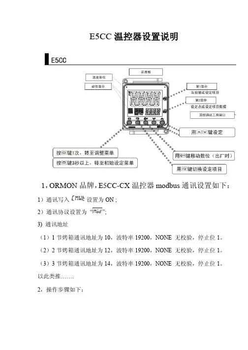
E5CC温控器设置说明
1,ORMON品牌,E5CC-CX温控器modbus通讯设置如下:1)通讯写入设置为ON ;
2)通讯协议设置为“”;
3) 通讯地址
(1)1节烤箱通讯地址为10,波特率19200,NONE 无校验,停止位1。
(2)2节烤箱通讯地址为12,波特率19200,NONE 无校验,停止位1。
(3)3节烤箱通讯地址为14,波特率19200,NONE 无校验,停止位1。
以此类推…….
2,操作步骤如下:
3, PID应用说明
1)在初始菜单中参数设定为PID;
2)操作步骤如下:
3)P或I或D值调整
4. 参数初始化
1)从操作菜单(即现显示温度界面),同时和
约5秒后进入保护菜单
2)把保护菜单中第2参数CCPt把1改成0,2秒后自动确定
3)“退出”同时和2秒,退出成功。
4)按3秒进入初始菜单,第1参CN-t,接着
下翻,翻到,设置“-169”,2秒后进入
接着iNit设为ON即可,初始化完成‘
5)“退出”按1秒,退出成功。

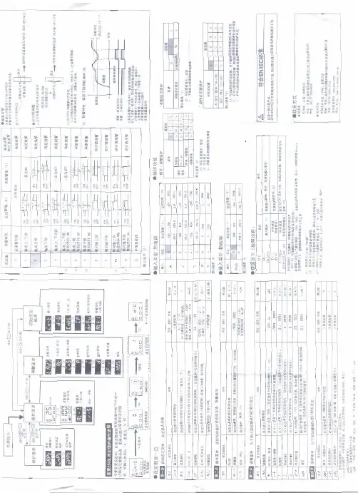
E5CSL/E5CWL T emperature Controller Instruction Manual Thank you for purchasing the OMRON E5CSL/E5CWL Temperature Controller. This manual describes the functions, performance, and application methods needed for optimum use of the product.Please observe the following items when using the product.• This product is designed for use by qualified personnel with a knowledge of electrical systems.• Before using the product, thoroughly read and understand this manual to ensure correct use.• Keep this manual in a safe location so that it is available for reference whenever required.©All Rights Reserved Suitability for Use OMRON shall not be responsible for conformity with any standards, codes, or regulations that apply to the combination of the products in the customer's application or use of the product. Take all necessary steps to determine the suitability of the product for the systems, machines, and equipment with which it will be used.Know and observe all prohibitions of use applicable to this product.NEVER USE THE PRODUCTS FOR AN APPLICATION INVOLVING SERIOUS RISK TO LIFE OR PROPERTY WITHOUT ENSURING THAT THE SYSTEM AS A WHOLE HAS BEEN DESIGNED TO ADDRESS THE RISKS, AND THAT THE OMRON PRODUCT IS PROPERLY RATED AND INSTALLED FOR THE INTENDED USE WITHIN THE OVERALL EQUIPMENT OR SYSTEM.See also product catalog for Warranty and Limitation of Liability.CAUTION Do not touch the terminals while power is being supplied. Doing so may occasionally result in minor injury due to electric shock.Do not allow pieces of metal, wire clippings, or fine metallic shavings or filings from installation to enter the product. Doing so may occasionally result in electric shock, fire, or malfunction.Do not use the product where subject to flammable or explosive gas. Otherwise, minor injury from explosion mayoccasionally occur.Never disassemble, modify, or repair the product or touch any of the internal parts. Minor electric shock, fire, or malfunction may occasionally occur. If the output relays are used past their life expectancy, contact fusing or burning may occasionally occur. Always consider the application conditions and use the output relays within their rated load and electrical life expectancy. The life expectancy of output relays varies considerably with the output load and switching conditions.Tighten the terminal screws to between 0.74 and 0.90 N·m. Loose screws may occasionally result in fire.Set the parameters of the product so that they are suitable for the system being controlled. If they are not suitable, unexpected operation may occasionally result in property damage or accidents.EN Models with Single Display Models with Dual Display E5CSL- R Relay output: 250 VAC, 3 A Q Voltage output (for driving SSR): 12 VDC, 21 mA Control output 131Sensor type 31 Relay output: 250 VAC, 1 A (resistive load)Alarm (E5CWL only)2E5CWL- 1123• Insert the Controller through the hole in the panel. Push the adapter on from therear to secure the Controller.• Make sure that the surrounding temperature does not exceed the allowable operating temperature given in the specifications, especially when two or more Controllers are mounted.• The voltage output (control output) is not electrically isolated from the internalwiring. One or the other of the control output terminals must therefore be leftungrounded when using a grounded thermocouple thermometer. (If both are grounded, measurements will be unreliable due to sneak current.)Individual Mounting Side-by-side Mounting TC Thermocouple (K, J, T, R, or S)P Platinum resistance thermometer (Pt100)The standby sequence is cleared when the alarm OFF condition has been met.The standby sequence is started again when any of the following conditions is met.• Operation is started (power is turned ON or operation is switched from stop to run).• The alarm value is changed.• The temperature input offset is changed.• The set point is changed.Standby sequence clearedAlarm value Alarm with standby sequenceProcess value TimeAlarm without standby sequence Example: Deviation Lower Limit Standby Sequence ONThe default alarm type is 2.• The control output and the alarm output will turn OFF when an error occurs.(For s.err , the alarm output will be processed for a high temperature error.)• If the input value exceeds the display limit (-1999 to 9999) but it is still within the control range, [[[[ will be displayed for values under -1999.Under these conditions, the control output and alarm output will operate normally.*1: This error is displayed only when the process value and set point are displayed.*2: If the display does not change, the Controller needs to be repaired.If operation returns to normal, then noise may have caused the problem. Check for noise.*3: On the E5CSL, e111 and sum will alternate on the display at 1-second intervals.On the E5CWL, e111 will be displayed on display No. 1 and sum will be displayed on display No. 2. * * * * *The default input type is 8.The default input type is 0.−300 to 23000.0 to 900.0−100 to 15000.0 to 750.0−300 to 700−199.9 to 700.00 to 30000 to 3000−200 to 1300−20.0 to 500.0−100 to 850−20.0 to 400.0−200 to 400−199.9 to 400.00 to 17000 to 1700Input Setting range (°C)Setting range (°F)t -n i l.adj t p a o Input Typeinpt at AT Execute/Cancel d-u Temperature Unit s n i t p k o TemperatureInput Shift cntl PID • ON/OFF al-1Alarm Value*E5CWL only p Proportional Band cp Control Period r-s RUN/STOP i Integral Time oreV Direct/ReverseOperation d Derivative Time alt1Alarm Type *E5CWL only of-r hys HysteresisOperation/Adjustment Protect Initial Setting Protect Operation Control Key Protect PV/SP Set Point *E5CSL only Manual Reset Value Adjustment Level 100SP 25SP for less for at least 3 seconds.Protect Level Operation Level +Adjustment Level POWER ON Initial Setting Level 100 to 240 VAC, 50/60 Hz85% to 110% of the rated voltageApprox. 3.5 VARelay output: 250 VAC, 3 A (resistive load)Voltage output (for driving SSR): 12 VDC+25%/−15%, 21 mA Relay output: 250 VAC, 1 A (resistive load)ON/OFF or 2-PID control 100,000 operations 250 ms −10 to 55°C (with no freezing or condensation)Thermocouple: K, J, T, R, or S (JIS C 1602-1995 and IEC 60584-1)Platinum resistance thermometer: Pt100(JIS C 1604-1997 and IEC 60751)Control output Recommended fuse Weight Degree of protection Alarm output Control method Electrical life of relay Sampling period Malfunction vibration Vibration resistance Ambient temperature Ambient humidity Storage temperature Altitude Installation environment Memory protection Indication accuracy (ambient temperature: 23°C)25% to 85%Power supply voltage Operating voltage range Power consumption −25 to 65°C (with no freezing or condensation)2,000 m max.T2A, 250 VAC, time-lag, low-breaking capacity Approx. 100 g (Controller only)Front panel: IP50, Rear case: IP20,Terminal section: IP00Installation category II,pollution degree 2 (as per IEC 61010-1)Non-volatile memory(number of write operations: 100,000)Sensor type Alarm type No alarm Deviation upper/lower limit Deviation upper limit Deviation lower limit Deviation upper/lower range D eviation upper/lower limit standby sequence ON Deviation upper limit standby sequence ON Deviation lower limit standby sequence ON Absolute value upper limit Absolute value lower limit Absolute value upper limit standby sequence ON Absolute value lower limit standby sequence ON Do not set.Output OFF Positive alarm value (X)Negative alarm value (X)Always ON Always OFF Always OFF Process value LevelSetting Adjustment LevelOperationLevel PV/SPOthers (Alarm Value): Operation control keys are enabled but operation control using parameters is disabled.: Operation control keys are disabled but operation control usingparameters is enabled.: Operation control keys and operation control using parametersare disabled.Default: 0Operation ControlAT Execute/Cancel (M +D )RUN/STOP (M +U )01234SettingLevel 10Do not set.2SettingInitial Setting Level Default: 1• Operation/Adjustment Protection • Initial Setting Protection • Operation Control Key Protection+−AB B Pt inputAlarm Output• Relay output: 250 VAC, 1 A(resistive load)Input power supply:100 to 240 VAC,50/60 HzDO NOT USE Control output +−TC inputM M MM M M M MM M M M M M MM M Step 3Adjustment Level: Used to tune parameters and set control parameters. Adjustment Level AT Execute/Cancel Temperature Input Shift Proportional Band Integral Time Derivative Time Manual Reset Value Hysteresis l.adj at ins p i d of-r hys This display indicates that you have moved to Adjustment Level.Starts and stops autotuning. (Displayed only when PID control is selected.)*1*2Set a compensation value for the temperature input in increments of 0.1°C or 0.1°F.Set the proportional band in increments of 0.1°C or 0.1°F.(Displayed only when PID control is selected.) Set the integral time in increments of 1 s. (Displayed only when PID control is selected.) Set the derivative time in increments of 1 s. (Displayed only when PID control is selected.) Set the manipulated value to use for P or PD control (I = 0). The offset will be canceled. Set the hysteresis to use to achieve stable operation when switching the control output ON/OFF during ON/OFF control. (Displayed only when ON/OFF control is selected.) off /on -199.9 to 999.90.1 to 999.90 to 39990 to 39990.0 to 100.00.1 to 999.9OFF 0.0 (°C)8.0 (°C)233 (s)40 (s)50.0 (%)1.0 (°C)Step 4Protect Level: Used to set parameters to restrict key operations.Operation/Adjustment Protect Initial Setting Protect Operation Control Key Protect oapt inpt okpt Set protection for Operation Level and Adjustment Level.Set protection for Initial Setting Level. Set protection for the AT Key and RUN/STOP Key (operation control keys). *Refer to table on the right.*Refer to table on the right.*Refer to table on the right. 010Step 2Operation Level: Used to monitor the process value and to set the set point, alarm value, etc.PV/SP Alarm value RUN/STOP Monitor the process value and set the set point.Set the alarm value. The location of the decimal point depends on the input type. *E5CWL only.Start and stop control operation. *1-1999 to 9999run /stop SV: 0 (°C)0 (°C)RUN Display Parameter name Description Setting/monitoring range Default Step 1Initial Setting Level: Used to set basic specifications.Input Type Temperature Unit PID • ON/OFF Control Period Direct/Reverse Operation Alarm Type in-t d-u cntl cp ore?alt1Set the input sensor type.Set the unit for temperature input to Celsius (°C) or Fahrenheit (°F).Set either 2-PID control or ON/OFF control.Set the time-proportional control period for the control output. (Displayed only when PID control is selected.) Set either reverse option (heating control) or direct operation (cooling control). Set the alarm type.*E5CWL only.c (°C)/f (°F)onof /pid 0.5, 1 to 990 or 8°C ON/OFF 20 or 2 (s)Or-r (reverse control)2 (Deviation upper limit)or-r (reverse control)or-d (direct control)*1: Displayed only when Operation Control Key Protection is set to 4.*2: The setting cannot be changed during autotuning. Autotuning will be stopped if you move to Initial Setting Level or stop control operation. • Displays during AutotuningE5CSL: The current deviation indicator will flash. E5CWL: The AT Execute/Cancel characters on display No. 1 and the PV/SP characters on display No. 2 will flash.K J T R S Setting 01234567Check the wiring of inputs, disconnections, short circuitsand input type.T urn the power OFF then back ON again.*2Press the U and D Keys for at least 3 seconds to initialize the settings and clear the non-volatile memory error.*2Display Action s.err (S.ERR)e111(E111)e111/sum (E111)/(SUM) *3Meaning Input error *1RAM memory error Non-volatile memory memory error −300 to 1500−199.9 to 900.0−200 to 850−199.9 to 500.0Pt10089Safety Precautions Indicates a potentially hazardous situation which, if not avoided, is likely to result in minor or moderate injury or property damage. Read this manual carefully before using the product.CAUTION Package Contents • Temperature Controller • Adapter • Instruction Manual 460645844.8×44.848×48Adapter • Solderless terminal size: M3.5• Terminal Cover: E53-COV19 (sold separately)• Front Panel: E53-COV20 (sold separately)Recommended panel thickness is 1 to 5 mm.1(10) D Down Key: Reduces the setting.(11) U Up Key: Increases the setting.(12) O +M Press these keys for at least 3 seconds in Operation Level or Adjustment Level to go to Protect Level.Press these keys for at least 1 second in Protect Level to return to Operation Level.(13)M +D Press these keys for at least 2 seconds to start or stop autotuning.*1(14) M +U Press these keys for at least 2 seconds to start or stop operation.*2(3)(7)(4)(9)(8)(12)(13)(14)(11)(12)(13)(14)(11)(10)(2)(1)(10)(6)(6)(7)(8)(5)(1)(9)E5CSL E5CWL D Key or U Key Input Type Parameter Display Parameter SettingDisplay Press the U or D Key at the display for the parameter for which the setting is to be changed. The parameter setting display will appear.Use the U or D Key to change the setting. Example: Changing the Input Type from 0 to 1in-t 0Procedure for Changing E5CSL Settings After 2 seconds U Flashes quickly.Setting confirmed.*1: These keys are disabled when starting and stopping autotuning has been disabled with operation control key protection.*2: These keys are disabled when starting and stopping operation has been disabled with operation control key protection.Control Output• Relay output: 250 VAC, 3 A (resistive load)• Voltage output (for driving SSR): 12 VDC, 21 mAAlarm hysteresis(always 0.2 °C/°F)23457891045+0.60+1.004560 min.+0.6045+0.60(48 x number of Controllers − 2.5)OMRON CORPORA TION Key to Warning Symbols Warning Symbols SpecificationsWiring Model Number Legends Dimensions (mm)Installation (mm)Connections Front Panel Part Names and Functions(1) Display No. 1 Displays the process value (PV) or parameter. For the E5CSL, the set point or parameter setting is also displayed.(2) Display No. 2 Displays the set point (SP) or parameter setting.(3) Deviation Indicators Show the relation between the process value and the set point. Lit: The process value is more than 5°C/°F higher than the set point. Lit: The process value is more than 5°C/°F lower than the set point. Lit: The process value is within 5°C/°F of the set point. The relevant deviation indicator will flash during autotuning.(4) SP Lit while the set point is displayed on display No. 1 (E5CSL only). (5) ALM Lit while the alarm is ON. Not lit while the alarm is OFF. (6) OUT Lit while the control output is ON. Not lit while the control output is OFF.(7) STOPNot lit during operation. Lit while operation is stopped.(8) O Level Key: Changes the setting level.(9) M Mode Key: Changes the parameter within the setting level.Operation MenuParameter Operations Press Press than 1 second.for at least 1 second.Press Parameter Tables Display Parameter name Description Setting/monitoring range Default Display Parameter name Description Setting/monitoring range Default Display Parameter name Description Setting/monitoring range Default *Refer to table on the right.*Refer to table on the right.al-1r-s Input type: Thermocouple Input Setting range (°C)Setting range (°F)Setting Input type: Platinum Resistance Thermometer Troubleshooting Protection : Can be displayed and changed.: Can only be displayed.: Display or changing to another level is not possible.0 1 2 311OMRON EUROPE B.V.Wegalaan 67-69, NL-2132 JD Hoofddorp The NetherlandsPhone 31-2356-81-300 FAX 31-2356-81-388OMRON ELECTRONICS LLCOne Commerce Drive Schaumburg, IL 60173-5302 U.S.APhone 1-847-843-7900 FAX 1-847-843-7787OMRON ASIA PACIFIC PTE. LTD.No. 438A Alexandra Road # 05-05/08 (Lobby 2),Alexandra Technopark, Singapore 119967 Phone 65-6835-3011 FAX 65-6835-2711OMRON Corporation Shiokoji Horikawa, Shimogyo-ku, Kyoto 600-8530 JAPAN Malfunction shock Shock resistance 10 to 55 Hz, 20 m/s 2 for 10 min each in X, Y and Z directions 10 to 55 Hz, 20 m/s 2 for 2 h each in X, Y and Z directions100 m/s 2, 3 times each in X, Y, and Z directions300 m/s 2, 3 times each in X, Y, and Z directionsMd-u Next Parameter Display*The dimensions are the same for the E5CSL.(±0.5% of indication value or ±1°C, whichever is greater)±1 digit max.R, S thermocouple at 200°C or less: ±3°C ±1 digit max.K, T thermocouple at −100°C or less: ±2°C ±1 digit max.Use a deviation alarm to link the alarm to the SP.If the SP is changed, the alarm operating point will also change.Deviation AlarmUse an absolute value alarm when the alarm is not linked to the SP.Absolute Value Alarm0X ON OFF SP X ON OFF SP X ON OFF SP X ON OFF 0X ON OFF 0X ON OFF 0X ON OFF 0X ON OFF ON OFF SP X XSP XON OFF SP XON OFF SP X X ON OFF SP X X ON OFF SP X ON OFF SP X ON OFF 0X ON OFF0XON OFF 0X ON OFF Set this difference.SP Linked Fixed Set the difference(deviation) from the SP.Set the alarm operating point as the temperature (absolute value).Set the temperature (absolute value) at which to output an alarm.0* Alarms with a Standby SequenceSP X ON OFFAlarmsSetting 0 1 2 3 4 5 6 7 8 9 1011 12Alarm operating point Alarm operating point The alarm is blocked until the first safe-state is reached.Unwanted alarm during start-up are prevented.Deviation/ab solute value alarm Deviation alarmDeviationalarm DeviationalarmDeviation alarm Deviation alarm Deviationalarm Deviationalarm Absolute value alarm Absolutevalue alarm Absolute value alarmAbsolute value alarm Be sure to observe the following precautions to prevent operation failure, malfunction, or adverse affects on the performance and functions of the product. Not doing so may occasionally result in unexpected events.(1) The product is designed for indoor use only. Do not use the product outdoors or in any of the following locations. •Places directly subject to heat radiated from heating equipment.•Places subject to splashing liquid or oil atmosphere. •Places subject to direct sunlight. •Places subject to dust or corrosive gas (in particular, sulfide gas and ammonia gas). •Places subject to intense temperature change.•Places subject to icing and condensation. •Places subject to vibration and large shocks.(2) Use/store within the rated temperature and humidity ranges. Provide forced-cooling if required.(3) To allow heat to escape, do not block the area around the product. Do not block the ventilation holes on the product.(4) Be sure to wire properly with correct polarity of terminals.(5) Use specified size (M3.5, width 7.2 mm or less) crimped terminals for wiring. To connect bare wires to the terminal block, use copper braided or solid wires with a rated temperature of over 70°C and a gauge of AWG24 to AWG14 (equal to a cross-sectional area of 0.205 to 2.081 mm 2). (The stripping length is 5 to 6 mm.) Up to two wires of same size and type, or two crimped terminals can be inserted into a single terminal.(6) Do not wire the terminals which are not used.(7) Allow as much space as possible between the controller and devices that generate a powerful high- frequency or surge. Separate the high-voltage or large-current power lines from other lines, and avoid parallel or common wiring with the power lines when you are wiring to the terminals.(8) Use this product within the rated load and power supply.(9) Make sure that the rated voltage is attained within two seconds of turning ON the power using a switch or relay contact. If the voltage is applied gradually, the power may not be reset or output malfunctions may occur.(10) Make sure that the Controller has 30 minutes or more to warm up after turning ON the power before starting actual control operations to ensure the correct temperature display. (11) A switch or circuit breaker should be provided close to this unit. The switch or circuit breaker should be within easy reach of the operator, and must be marked as a disconnecting means for this unit.(12) Do not use paint thinner or similar chemical to clean with. Use standard grade alcohol.(13) Design system (control panel, etc) considering the 2 second of delay that the controller’s output to be set after power ON.(14) The output may turn OFF when shifting to certain levels. Take this into consideration when performing control.(15) The number of non-volatile memory write operations is limited.Precautions for Safe Use A malfunction in the Temperature Controller may occasionally make control operations impossible or prevent alarm outputs, resulting in property damage. To maintain safety in the event of malfunction of the Temperature Controller, take appropriate safety measures, such as installing a monitoring device on a separate line.Default: 0: Can be displayed and changed.: Display or changing to another level is not possible.2113603-9A CL1for at least 3 seconds.Press for at least 1 second.+Press。

E5□C 温度控制器简易操作说明书动作显示的说明动作显示名称概要SUB1SUB2SUB3SUB4辅助输出1~4(仅E5CC/EC/AC 有辅助输出3)(仅E5EC/AC 有辅助输出4)辅助输出1~4的分配功能ON 时灯亮。
OUT1OUT2控制输出1、2(仅E5CC/CC-U/EC/AC 有控制输出1)(仅E5CC/CC-U/EC/AC 有控制输出2)向控制输出1、2分配的功能ON 时灯亮。
MANU手动手动模式时灯亮STOP停止运行停止时灯亮TUNE AT、ST 执行中执行AT (自动调节)期间灯亮。
执行ST(自调节)期间闪烁。
RSP 远程SP(仅E5CC/EC/AC)“SP 模式”为远程SP 时灯亮。
远程SP 模式下RSP 输入异常时闪烁。
设定变更保护设定变更保护ON 时灯亮。
操作键的说明操作键名称概要说明菜单键切换设定菜。
转移方的设定菜单根据按下的时间而异.在操作菜单中,.按1次(1秒以下)菜单键:转至调整菜单。
.持续按下3秒以上:转至初始高定菜单。
在调整菜单中,.按1次(1秒以下)菜单键:转至操作菜单。
.持续按下3秒以上:转至初始设定菜单。
在初始设定菜单中,.按下菜单键1秒以上:转至操作菜单。
模式键移动设定菜单内项目。
.按1次该键,则移动到下一模式。
.如按信不放,则反向移动。
向下/向上键设定数值。
.如果按住不放,则数值快速增减。
.设定后,设定值将在以下情况时得到反映。
.经过3秒以上时:.按下键时。
.按下键转换菜单时。
移位键(PF)键用户定义功能键.每按键1次(不到1秒),可将其用作移位键。
.选择需变更的数位(出厂时)。
.按键,可在高级功能设定菜单的“PF 设定”中分配以下功能:.运行/停止反转、自动/手动反转、AT(自动调节)执行、报警闩锁解除、监控/设定项目的显示、移位(出厂时)例)将高级功有菜单的“PF 设定”设定为“STOP”时,按键1秒以上,运行停止。
.设定为监控/设定项目“PFDF”时,每按键1次(不到1秒),切换并显示在高级功能设定菜单的“PF监控/设定项目1~5“中设定的项目。
