ALTEK 多功能校验仪TechChek 820
- 格式:pdf
- 大小:1.94 MB
- 文档页数:4
820-2StroboscopeManual de usoSeptember 2014 (Spanish)© 2014 Fluke Corporation. All rights reserved. Specifications are subject to changewithout notice. All product names are trademarks of their respective companies.GARANTÍA LIMITADA Y LIMITACIÓN DERESPONSABILIDADSe garantiza que este producto de Fluke no tendrá defectos en los materiales ni en la mano de obra durante dos años a partir de la fecha de adquisición. Esta garantía no incluye fusibles, baterías desechables ni daños por accidente, negligencia, mala utilización o condicionesanómalas de funcionamiento o manipulación Los revendedores no están autorizados para otorgar ninguna otra garantía en nombre de Fluke. Para obtener serviciotécnico durante el período de garantía, envíe el detector defectuoso al centro de servicio Fluke autorizado junto con una descripción del problema.ESTA GARANTÍA ES SU ÚNICO RECURSO. NO SE CONCEDE NINGUNA OTRA GARANTÍA, EXPRESA O IMPLÍCITA, TAL COMO AQUELLA DE IDONEIDAD PARA UN PROPÓSITO DETERMINADO. FLUKE NO SE RESPONSABILIZA DE PÉRDIDAS NI DAÑOS ESPECIALES, INDIRECTOS, IMPREVISTOS O CONTINGENTES, QUE SURJAN POR CUALQUIER TIPO DE CAUSA O TEORÍA. Dado que algunos países o estados no permiten la exclusión o limitación de una garantía implícita, ni de daños imprevistos o contingentes, las limitaciones de esta garantía pueden no ser de aplicación a todos los compradores.Fluke CorporationP.O. Box 9090Everett WA 98206-9090 EE.UU. Fluke Europe B.V. P.O. Box 11865602 B.D. Eindhoven Holanda11/99Tabla de materiasTítulo Página Introducción (1)Contacto con Fluke (1)Seguridad (2)Símbolos (3)Equipo estándar (4)Características (5)Apagado automático (8)Indicador de batería baja (8)Uso del Producto (9)Parámetros predeterminados (9)Menú Conf (10)Rango (10)Disparo externo (11)Mantenimiento (11)Limpieza del Producto (12)Cómo cambiar las pilas (12)Especificaciones (14)Especificaciones mecánicas (14)Especificaciones ambientales (14)Especificaciones (16)i820-2Manual de usoiiLista de tablasTabla Título Página1. Símbolos (3)2. El Producto (6)3. Visualización (7)Lista de figurasTítulo Página Figura1. El Producto (5)2. Polaridad del conector del activador externo (11)3. Cambio de pilas (13)iii820-2Manual de usoivIntroducciónEl Estroboscopio 820-2 (el Producto) usa una luz LEDestroboscópica para mostrar el movimiento de piezas mecánicas. El rango de frecuencia es de 30 a 300.000 FPM (Flashes por minuto).Contacto con FlukePara ponerse en contacto con Fluke, llame a uno de los siguientes números de teléfono:•Asistencia técnica en EE. UU.: 1-800-44-FLUKE(1-800-443-5853)•Calibración y reparación en EE. UU.: 1-888-99-FLUKE (1-888-993-5853)(1-800-363-5853)• Canadá:1-800-36-FLUKE•Europa: +31 402-675-200+81-3-6714-3114• Japón:+65-6799-5566• Singapur:•Desde cualquier otro país: +1-425-446-5500Vaya a para registrar el producto, descargar manuales y obtener más información.Para ver, imprimir o descargar el último suplemento del manual, visite /usen/support/manuals.1820-2 Manual de uso2SeguridadUna Advertencia identifica condiciones y procedimientos que son peligrosos para el usuario.AdvertenciaPara evitar posibles lesiones personales:•Lea toda la información de seguridad antes de usar el Producto. •Lea atentamente todas las instrucciones. • Utilice el Producto únicamente de acuerdo con las especificaciones; en caso contrario, sepuede anular la protección suministrada por elProducto.• No toque el objeto en movimiento cuando utilice el Producto. Bajo la iluminaciónestroboscópica puede parecer que el objeto enmovimiento está quieto o que se muevelentamente.• No utilice el Producto cerca de gases o vapores explosivos, o en ambientes húmedos omojados.• No utilice el Producto cerca de personas que padezcan problemas de epilepsia.•No utilice el producto si está dañado.StroboscopeSímbolos3SímbolosLos símbolos utilizados en este manual y en el Producto se muestran en la tabla 1.Tabla 1. Símbolos Símbolo DefiniciónRiesgo de peligro. Información importante. Consulte el manual.PilaCumple con la normativa australiana sobre compatibilidad electromagnética EMCCumple la normativa de la Unión Europea. Cumple con las normas surcoreanas sobrecompatibilidad electromagnética (EMC).Este Producto cumple la Directiva WEEE(2002/96/EC) sobre requisitos de marcado. Laetiqueta que lleva pegada indica que no debedesechar este producto eléctrico o electrónico conlos residuos domésticos. Categoría del producto:Según los tipos de equipo del anexo I de la DirectivaWEEE, este producto está clasificado como productode categoría 9 "Instrumentación de supervisión ycontrol”. No se deshaga de este producto mediantelos servicios municipales de recogida de basura noclasificada. Para obtener información sobre elreciclado, visite el sitio web de Fluke.820-2 Manual de uso4 Equipo estándarSi le falta algún elemento de los siguientes o si alguno está dañado, póngase en contacto con Fluke. El Producto incluye: •Guía de referencia rápida •Información sobre seguridad •Tarjeta de registro internacional • Declaración de calidad• Estuche rígido•Baterías AA (3) • Conector de entrada de activador externoCaracterísticasCaracterísticasEl Producto se muestra en la Figura 1, Tabla 2 y Tabla 3.Figura 1. El ProductoManual de usoTabla 2. El ProductoElemento Descripción PantallaBotón de encendido. Pulse para encender el Producto. Mantenga pulsado 2 segundos para apagar el Producto.Pulse para dividir el valor actual establecido entre dos. La velocidad de desplazamiento aumenta si se deja pulsado de forma continua.Conexión de activador externoConfiguración. Pulse para desplazarse entre los diferentes ajustes y modos.Pulse para duplicar el valor actual establecido. La velocidad de desplazamiento aumenta si se deja pulsado este botón.Estroboscopio LEDPulse el activador ( ) hacia arriba para aumentar el valor actual establecido. Pulse hacia abajo para reducir el valor actual establecido. La velocidad aumenta al dejar pulsado .Compartimento para la bateríaCaracterísticas Tabla 3. PantallaManual de usoTabla 3. Pantalla (cont.)Elemento Descripción Elemento DescripciónBateríasdescargadas.Reemplace labatería.1/min o RPMpara entrada deactivadorexterno.Flashes porminuto (FPM),valorpredeterminadoen el encendido.Flashes porsegundo. Elajuste seencuentra en elmenú deconfiguración.Retraso deimpulso en grados(grado de fase). Elajuste seencuentra en elmenú deconfiguración.Retraso de pulsoen milisegundos(ms). El ajuste seencuentra en elmenú deconfiguración.Activador internoApagado automáticoPara ahorrar batería, el Producto se desconecta tras 15 minutos de inactividad.Indicador de batería bajaEl indicador de batería baja aparece cuando la batería tiene poca carga. Cuando aparezca el indicador de batería baja ( ), cambie las pilas.Uso del ProductoUso del ProductoEn las siguientes secciones se explica cómo usar el Producto.Pulse para encender el Producto. Mantenga pulsado2 segundos para apagar el Producto.Parámetros predeterminadosPara restablecer el Producto a los ajustes predeterminados, mantenga pulsados y .Los ajustes predeterminados son:FPM• 1000• 16,7Hz•Pulso de 333 μs•Pulso de 2,0 grados•Retraso de 0 ms•Fase de 0 grados•Divisor de pulso externo = 1•Límite de activador externo = 0 (positivo)Manual de usoMenú ConfAl pulsar , aparece el menú de configuración. Desde ese menú puede cambiar los siguientes parámetros:•Hz. Ajuste los flashes por segundo en Hz.•Ancho de pulso en μs ( ). Ajusta la intensidad del flash en microsegundos de ancho de pulsos.•Ancho de pulso en grados ( ). Ajusta la intensidad del flash en grados de la velocidad de flash.•Retraso en ms ( ). Ajusta el retraso en milisegundos entre el activador interno y el flash. Con este ajuste se puede realizar un ajuste preciso de la posición de observación.•Grado de fase ( ). Ajusta los grados del cambio de fase entre el activador interno y el flash. Con este ajuste se puede realizar un ajuste preciso de la posición de observación. •Divisor de pulso de activador externo ( ). Ajusta el divisor del activador externo para establecer la velocidad de flash.•Límite de activador externo ( ). Ajusta el límite del activador externo en positivo (0) o negativo (1).Pulse , y para realizar ajustes en los parámetros. Pulse para cambiar los parámetros y para entrar y salir del menú de configuración.RangoSi el activador externo es >5 kHz, en la pantalla aparece -OL-. Si el activador externo es <0,5 Hz, en la pantalla aparece -UL-.MantenimientoDisparo externoUtilice el conector de entrada de activador externo para enchufar fuentes de activación exteriores. Cuando se enchufa el conector al Producto (consulte la Figura 1, elemento ) en el Producto aparece . La Tabla 3 muestra las opciones disponibles al utilizar un activador externo. Para obtenerinformación sobre la polaridad del conector consulte la Figura 2.gsh04.epsFigura 2. Polaridad del conector del activador externoMantenimientoPrecauciónEl Producto no contiene piezas que puedan ser reparadas por el usuario. Para evitar que seproduzcan daños en el Producto, no lo abra. Para repararlo, consulte la sección de Contacto con Fluke.+-Manual de usoLimpieza del ProductoLimpie regularmente el estuche con un trapo húmedo y detergente suave.PrecauciónPara evitar daños en el producto, no use disolventescon cloro o hidrocarbonos perfumados para limpiarel producto.Cómo cambiar las pilasEl Producto se alimenta con tres pilas AA (LR6). Cambie las pilas cuando en la pantalla aparezca el símbolo de batería baja ( ). Consulte la Figura 3.PrecauciónPara evitar que el producto resulte dañado:•Asegúrese de que la polaridad de las pilas escorrecta para evitar fugas.•Si no va a utilizar el producto durante unperiodo de tiempo prolongado, quite las pilaspara evitar que se produzcan fugas o daños.MantenimientoFigura 3. Reemplazo de las pilasManual de usoEspecificacionesEspecificaciones mecánicasTamaño(Alt. x Anch. x Prof.) ............ 5,71 cm x 6,09 cm x 19,05 cm(2,25 x 2,4 x 7,5 pulg.)Peso .................................... 0,24 kg (0,53 lb)Especificaciones ambientalesTemperatura defuncionamiento .................... D e 0 °C a +45 °C (+32 °F a +113 °F) Temperatura dealmacenamiento .................. D e -10 °C a +50 °C (+14 °F a +122 °F) Humedad defuncionamiento ................. S in condensación, < +50 °F (< +10 °C)90 % HR, de +10 °C a +30 °C(+50 °F a +86 °F)75 % HR, de +30 °C a +40 °C(+86 °F a +104 °F)45 % HR, de +40 °C a +50 °C(+104 °F a +122 °F)condensación) (sinAbsorción/corrosión .......... +30 °C (+86 °F), 95 %HR, 5 díasFuncionamiento normal del ProductoAltitud de funcionamiento .... 2.000 mAltitud de almacenamiento .. 12.000 mVibración ............................. M IL-PRF-28800F Clase 2StroboscopeEspecificacionesSeguridad ........................... IEC 61010-1, grado de contaminación 2 Entorno electromagnético ... IEC 61326-1: industrialGrupo 1, equipo ISM: el grupo 1 incluye todo el equipo ISM enel que se genera o se utiliza intencionadamente la energía de radiofrecuencia acoplada conductivamente necesaria para el funcionamiento interno del equipo.Clase A. El equipo es apto para el uso en emplazamientos no residenciales o conectado directamente a una red dealimentación de baja tensión. Los equipos de clase A pueden tener problemas potenciales para garantizar su compatibilidad electromagnética en otros medios, debido a alteraciones tantoen cables como en radiaciones.Compatibilidadelectromagnética ............... aplicable solo para su uso en Corea.Equipo de Clase A (Equipo dedifusión y comunicación industrial) [1] [1] El vendedor o usuario debe tener en cuenta que este productocumple con los requisitos industriales de onda electromagnética(Clase A). Este Equipo está diseñado para su uso en entornoscomerciales, no domésticos.15820-2 Manual de uso16 EspecificacionesTipo de pilas ........................ 3 x AA alcalinas LR6 Frecuencia de flashRango ............................. D e 30 a 300.000 FPM 0,5 Hz a 5000 Hz Precisión ......................... 0,02 %Resolución ...................... D e 30 a 999 FPM = 0,1Resolución De 30 a 300.000 FPM = 1De 0,5 a 999 Hz = 0,1De 1000 a 5000 Hz = 1 Ajuste de frecuencia ........... F PM o Hz Pulso de flashDuración ........................ A justable en μs o grados Retraso ......................... A justable en ms o grados LuzColor ............................. A prox. 6500 KSalida de emisión ......... 4800 lx a 6000 FPM30 cm (11,9 pulg.) a 3°Disparo externoMétodo .......................... C onector con disparador de control externoRango de frecuencia ..... D e 0,5 a 5000 HzNivel alto ....................... D e 3 a 32 VNivel bajo ...................... <1 VAncho de pulso mínimo .......................... C onexión de 50 μs。
BETA90多功能校验仪用户手册武汉奥泰克仪器仪表有限公司WUHAN ALTEK INSTRUMENT & METER CO.LTD61、简介BETA90是一种便携式、由电池供电的多功能过程校验仪,该设备可测量或模拟输出多种电信号和物理量。
BETA90具有如下功能及特点:● 具有双通道显示,显示屏上半部分的显示区域可显示电压、电流和压力的测量值,显示屏下半部分的显示区域可显示电压、电流、压力、热电阻、热电偶、频率和电阻的测量值,还可以模拟输出脉冲值。
● 热电偶输入/输出端带有自动冷端温度补偿。
● 每个电信号或物理量的测量量程范围内均可设定5个递增或递减数值点。
● 互动式的使用菜单。
● 可使用自带的RS232接口进行远程控制。
● 独立的重复读数功能可校验变送器。
1.1 标准配置一套完整的BETA90应包括如下部分:主机,使用手册,测量导线3套,橡胶外壳,NIST 证书,便携式手提包(可选件:型号为CC572)。
1.2 安全事项请在使用BETA90时需注意以下几点: ● 请勿超过额定电压。
详见量程范围说明 ● 遵循一切设备安全条例。
● 当测量导线插在电流测量端时,请不要使测量头接触电压源。
● 如BETA90已损坏请不要继续使用。
在使用前请检查仪器的外壳,查看是否有裂纹或缺口。
要特别注意连接导线的接头部位的绝缘材料是否完整。
● 测量时请选择正确的功能和量程。
● 使用前请确认电池仓的盖子是否已关严。
● 打开电池仓之前请将测量导线从BETA90上拔下。
● 检查测量导线的绝缘材料是否已经损坏或已有金属部分裸露在外,在使用BETA90前请将已坏的测量导线进行更换。
● 在使用测量导线的夹头时,手指部分请不要触摸夹头。
● 请勿非正常使用BETA90,这种行为可能会减少仪器的使用寿命。
在使用中如有疑问,请与我公司技术/售后服务部门联系。
● 请不要在含有爆炸性气体、蒸气或灰尘的环境中使用BETA90。
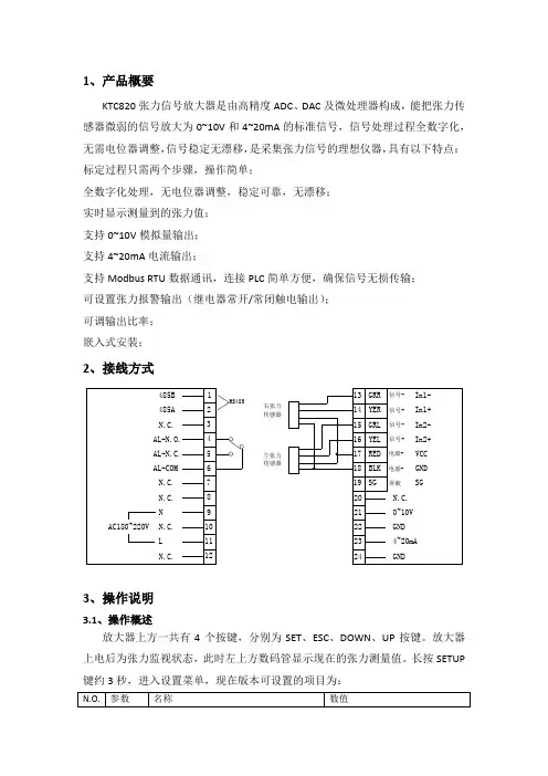
1、产品概要KTC820张力信号放大器是由高精度ADC 、DAC 及微处理器构成,能把张力传感器微弱的信号放大为0~10V 和4~20mA 的标准信号,信号处理过程全数字化,无需电位器调整,信号稳定无漂移,是采集张力信号的理想仪器,具有以下特点: 标定过程只需两个步骤,操作简单;全数字化处理,无电位器调整,稳定可靠,无漂移; 实时显示测量到的张力值; 支持0~10V 模拟量输出; 支持4~20mA 电流输出;支持Modbus RTU 数据通讯,连接PLC 简单方便,确保信号无损传输; 可设置张力报警输出(继电器常开/常闭触电输出); 可调输出比率; 嵌入式安装;2、接线方式3、操作说明3.1、操作概述放大器上方一共有4个按键,分别为SET 、ESC 、DOWN 、UP 按键。
放大器上电后为张力监视状态,此时左上方数码管显示现在的张力测量值。
长按SETUP 键约3秒,进入设置菜单,现在版本可设置的项目为:右张力传感器RS485N.C.N.C.L 左张力传感器AL-N.O.N.C.N.C.485B AL-N.C.NAC180~220V485A AL-COM N.C.2112111098765433.3请根据您的接线来设置本参数,如果单独接一个传感器且接在GRL和YEL上,GRR 和YER3.4传感器安装后,为了去除导辊和轴承等毛重对张力测量的影响,需要进行零张力标定,此时在安装完导辊,不通过材料的状态下进行。
Setup键进入,此时屏幕上闪烁显示0,此时再长按Setup键3秒,屏幕将会快速闪烁显示---,稍等一下便完成校准。
有一快捷进入方法,就是在张力监控状态下,长按Setup键5秒,便可自动进行零张力标定。
3.5(满量程标定,跨度标定)材料张力施加在传感器上的负载因传感器安装方向以及材料通过角度(包角)的不同而异,所以必须对此进行校正,进行满量程标定(跨度标定)。
标定步骤如下:Setup 键进入;如下图所示,按走料方向装上绳子,绳子一端固定,另一端悬挂已知重量的物体,把该物体的重量输入到放大器中;长按Setup 键3秒,放大器开始进行标定,此时快速闪烁---,稍等一下即可完成标定; 3.6该参数设定零张力时所对应的输出电压,可设置为0~10V ; 3.7该参数设定当张力等于满量程(满量程标定所设置的挂重值)时所对应的输出电压,可设置为0~10V 。
DTM820三相电力测量仪用户手册珠海大唐电子有限公司警告1、本设备只能由专业人员进行操作。
2、不认真按照手册上的说明操作而引起的故障,本公司将不承担任何责任。
危险1、本设备只能由专业人员进行安装和维护。
2、对本设备进行任何操作前,应隔离电压输入和电源供应,并且短路所有电流互感器的二次绕组。
3、在将本设备通电前,确认设备完整并所用的端子都已连接好。
4、供设备的电源电压范围在设备额定电压范围之内。
目录一、产品简介 (4)1.1 产品概述 (4)1.2 技术参数 (5)1.3 产品选型....................................错误!未定义书签。
1.4 功能介绍 (6)二、安装与接线 (11)2.1 安装 (11)2.1.1 外型和安装尺寸 (11)2.1.1 端子定义 (12)2.2 接线 (13)三、显示操作 (15)3.1概述 (15)3.2按键功能 (15)3.3数据查询 (16)3.4本地编程 (17)3.4.1配置参数的查看 (17)3.4.2配置参数的修改 (18)3.4.2.1仪表地址 (19)3.4.2.2 CT变比 (19)3.4.2.3测量模式 (20)3.4.2.4 PT变比 (20)3.4.2.5串口通讯速率 (20)3.4.2.6电度清除 (20)四、通讯协议 (21)一产品简介1.1 概述DTM820三相电量测控仪是一种简单可靠的测控装置,具有数据采集和控制功能。
可广泛应用于电力系统、智能楼宇、监控系统、低压配电等自动化领域。
该产品适用于低压和高压系统。
DTM820提供大液晶或高亮度数码管显示,和全方位的测量功能,如电压、电流、有功功率、无功功率、功率因数、频率、有功电度、无功电度等电参数,可以充分满足低压或者高压三相电力网络中电气监控的要求。
还具有很强的扩展功能,如监视开关状态的两路开关量输入(或两路脉冲输出)、控制开关动作的两路继电器报警输出(或两路4-20mA模拟量变送输出),以及通过RS485/MODBUS通讯,对仪表进行组网管理。

AMETEKASC300手持式多功能校准仪使用手册美国阿美特克公司图1 输入输出端子1.仪表布局表1 输入输出端子NO. 名称功能1,2 测量V, mA端子测量电流电压并提供回路电源3 TC测量和输出测量或模拟输出热电偶信号4,5 测量/输出V,RTD 2W,Hz测量或输出电压,频率,脉冲,2线热电阻6,7 测量/输出mA,3w,4wRTD 测量或输出电流,3线,4线热电阻8 压力模块接口连接外接压力模块测量压力9 串行通讯接口连接计算机实现远方控制图2显示了键盘的布局NO 名称功能1 F1,F2,F3功能键用来操作屏幕底部显示的菜单.2 BACK LIGHT背景光打开或关闭背景光3 HOME主菜单回到屏幕上的主菜单4 POWER电源校准仪电源开关5 0% 将键盘输入的一个值作为量程的0%.从内存中调出0%量程的值并作为输出值输出信号.6 25%以满量程25%增量的比例循环输出7 100% 将键盘输入的一个值作为量程的100%.从内存中调出100%量程的值并作为输出值输出信号.8 数字键允许用户直接输入数字图2 键盘2.屏幕和菜单2.1.屏幕显示图3 屏幕显示整个屏幕被划分为三个部分,上面的显示用来测量电压,电流和压力,下面的显示用来测量和输出各种参数,底部的菜单用来设置上面和下面屏幕的各种功能.表3 屏幕显示NO 名称功能1 主参数将要被输出或测量的参数.上面的屏幕主参数包括:VOLTS IN(电压输入),PRESSURE(压力),mA IN(测量电流),mA LOOP(测量电流内置回路电源)中间的屏幕的主参数包括:VOLT(电压),TC(热电偶),RTD(热电阻),FREQ(频率),PULSE(脉冲),PRESSURE(压力),MA(电流),MA 2W SIM(2线电流模拟)2 测量/输出控制切换中间的屏幕到测量(输入)或输出状态3 附加设置仅对TC和RTD有效.在TC状态下可以打开或关闭CJC(冷端补偿). 在RTD IN状态下指示2,3,4线制.4 量程百分比指示仅在mA和mA LOOP状态下有效.4mA对应0%,20mA对应100%.5 单位表示测量或输出值的单位,例如℃,℉,Hz,KHz,CPM6 温度探头类型表示热电阻和热电偶的分度号.也表示输出脉冲和频率的幅值以及压力单位7 数字显示显示信号的数字值.”OL”表示超出量程2.2 操作菜单屏幕上的各种参数需要通过菜单来控制调整.功能键F1,F2,F3用来设置菜单,这三个键分别对应菜单条的左,中,右三个菜单栏.任何时候按下HOME键可进入如下菜单,即总菜单.在总菜单中按F1可进入下一层菜单.总菜单中又包括三种总菜单:输入总菜单,输出总菜单和脉冲总菜单.在输入总菜单中只有MENU 一个键有效.输出总菜单下有三个有效的选项.除了MENU以外还有上下箭头用来调整输出值.频率总菜单下也有三个有效键,参见4.2-6总菜单下就是主菜单,主菜单中UPPER用来选择上面的屏幕,LOWER选择中间的屏幕.按下MORE可以进入设置状态,可以设置CONTRAST(屏幕对比度)按下NEXT可进入自动关机设置(AUTO OFF),调整自动关机时间.当校准仪处于频率状态时,从主菜单按MORE可进入频率幅值设置(FREQ LEVEL),用来调整输出频率的幅值.当校准仪处于RTD CUSTOM(自定义热电阻)状态时,通过主菜单按MORE可进入热电阻自定义菜单(SET CUSTOM),这项功能可以自定义热电阻参数.从主菜单按MORE 可进入压力清零菜单,可以对外接压力模块清零.在主菜单中选择了LOWER或UPPER后就进入了参数选择菜单.在这个菜单中SELECT用来用来改变参数内容,NEXT可以切换到下一个变量,DONE用来确认所选择参数和状态并回到主菜单.图4 菜单树3.使用测量模式(下屏幕)3.1测量电压和频率1.从主菜单中按LOWER进入中间的屏幕设置2.选择需要测试的参数3.如图5接线.图5 使用输入/输出端子测量电压或频率3.2测量mA电流1.切换到中间屏幕选择mA IN.2.如图6接线图6 测量mA3.3测量温度3.3.1使用热电偶校准仪支持B,C,E,J,K,L,N,R,S,T,U,BP,XK分度号的热电偶.CJC(冷端补偿)应该打开,这样测试的温度就是真实温度,只有在外部使用了冰点器时才可以关闭冷端补偿.1.如图7接线,将小插头插入校准仪接口.补偿导线必须和分度号对应.(最好等2到5分钟后进行测试,这样可以使小插头和校准仪的温度稳定.2.从主菜单按LOWER切换到中间屏幕.3.选择TC IN测试功能,并选择适当的分度号和温度单位.(校准仪也可以测试mV值,这样可以测试校准仪不支持的分度号.在探头种类参数中可以找到mV测量).图7使用热电偶测试温度3.3.2使用热电阻(RTD)可以使用2,3,4线制.如下图所示.(电阻测量功能可以通过选择探头种类而实现)图8使用热电阻测试温度3.4测试压力注意:高的压力系统存在危险,注意缓慢泄压.给压力模块加压不能超过最高限压.1.如图接线.压力可以在上屏幕和中间屏幕测量,这就可以同时使用两种单位测压.2.选择屏幕和压力测量,以及压力单位,测试之前对压力模块清零.(绝压模块清零参见模块说明)图9压力测试连接4.使用输出模式(下屏幕)ASC300校准仪可以输出标准信号用来测试和校准过程仪表.它可以输出电压,电流,电阻,频率,脉冲,和RTD,TC的电信号.4.1设置0%和100%输出参数1.从主菜单选择LOWER进入中间屏幕,选择合适参数.2.选择输出模式并给出具体值,例如选择VOLT OUT电压输出.3.用键盘输入5V,之后不按ENTER确认键,而是按0%键,这样就设置5V作为0%点4.输入20V并按100%,这就定义20V就是100%的值.5.使用25%键就可以在5V到20V之间以25%的增量循环.4.1.1电流输出步进使用mA输出25%步进功能如下操作1.选择中间的屏幕并选择mA.2.使用25%键就可以在4-20mA之间循环步进.4.2输出mA1.从主菜单选择中间屏幕并选mA作为主参数.2.选择OUT输出模式3.如下图连接电路4.用键盘直接输入电流值.图10输出电流4.3模拟变送器ASC300可以在电路中代替变送器并控制回路中的电流.1.从主菜单选择中间屏幕2.选择mA 2W SIM电流模拟功能并输入电流值3.如图接线图11模拟变送器4.4输出电压在中间屏幕选择电压输出VOLT OUT功能并如图接线.图12输出电压和频率4.5输出频率如上图接线,选择中间屏幕频率输出功能并选择单位,如果需要可改变频率幅值.4.6输出脉冲串1.选择下屏幕设置主参数为PULSE脉冲2.选择合适的单位并用键盘输入频率值3.从主菜单选择COUNTS功能并输入脉冲串数.使用TRIG功能开始或停止信号输出.4.脉冲的幅值可以调整,和频率幅值的调整方法一样.4.7输出热电偶如图接线并设置校准仪到TC OUT状态,选择合适的分度号和单位.图13 输出热电偶的连接图14输出热电阻接线4.8输出电阻/热电阻如图14接线,选择下屏幕,并设置状态到RTD OUT,选择合适的分度号和单位.图15 使用3线制和4线制测试热电阻接线4.8.1自定义RTD用户可以输入自定义分度表,步骤如下:1.切换到下屏幕,选择RTD并将探头种类选择为CUSTOM2.进入RTD自定义设置菜单,选择SET CUSTOM3.使用键盘输入各种参数:最小温度,最大温度,R0,以及每一个温度系数.5.使用测量功能(上屏幕)5.1测量电压和mA电流如下图接线并设置上屏幕到相应参数.图16隔离输入连接5.2内部回路电源供电测量电流测试2线制变送器可以用ASC300校准仪给变送器供电同时测量电流,如下图连接电路并设置上屏幕到mA LOOP状态.图17使用电流回路5.3测量压力如下图连接线路,在上屏幕选择PRESSURE参数进行压力测试.图18测试压力6.同时使用上下屏幕进行校准和测试图19输出信号给其它仪器6.1测试一个测量或指示设备利用ASC300输出功能可以测试和校准执行器,记录仪或其它指示设备.1.选择下屏幕并设定相应输出参数2.选择OUT输出信号3.连接线路如图19进行测试和校准6.2校准一个温度变送器1.以热电偶变送器为例,选择上屏幕测量电流mA LOOP.2.选择下屏幕,设置TC OUT进行热电偶输出并选择合适的分度号和温度单位3.根据温度量程设置0%和100%范围4.如图接线5.用25%键步进测试变送器0-25-50-75-100各点.6.如果需要调整变送器,并纪录校准数据图20校准温度变送器6.4校准压力变送器1.选择上屏幕,设置mA LOOP进行电流测量2.选择下屏幕选择PRESSURE测试压力3.如图22接线4.对压力模块清零5.测试压力变送器0%和100%,如果需要进行调整.图21校准压力变送器7.计算机控制ASC300可以和计算机连接进行通讯,通过WINDOWS操作系统的超级终端软件可以控制ASC300校准仪实现各种输入输出功能.图22与计算机连接8.指标如无特殊说明,指标是在环境温度23°C ±5°C进行测试得到的结果. 超过此温度范围的补偿系数为± 0.005%读数/°C.一般指标操作温度-10°C to 50°储存温度-20°C to 70°C电源 4 X AA 电池低电压报警Yes串行通讯接口Yes, A SCIICE – EMC认证EN50082-1: 1992 and EN55022: 1994 Clas s B 安全CSA C22.2 No. 1010.1: 1992DC 电压测量/输出量程准确度(% 读数±基数)0.000V– 30.000V0.015% ± 2mV测量:隔离(上屏幕)0.000V – 20.000V0.015% ± 2mV测量:非隔离(下屏幕)输出0.000V – 20.000V0.015% ± 2mV 在电压量程内最大输出电流 1mA,输出内阻 <= 1Ω.DC mA测量/输出量程准确度(% 读数±基数)0.000mA – 24.000mA0.015% ± 2µA测量:隔离(上屏幕)0.000mA – 24.000mA0.015% ± 2µA测量:非隔离(下屏幕)输出0.000mA – 24.000mA0.015% ± 2µA 最大负载 1000Ω.在电流模拟状态下电压输入范围5V – 30V.频率测量/输出量程准确度(% 读数±基数) 测量 2.0CPM – 600.0CPM 0.05% ± 0.1CPM1.0Hz – 1000.0Hz 0.05% ± 0.1Hz1.00KHz – 10.00KHz 0.05% ± 0.01KHz输出 2.0CPM – 600.0CPM 0.05%1.0Hz – 1000.0Hz 0.05%1.00KHz – 10.00KHz 0.125%测量频率电压幅值1V to 20V.输出幅值 1V to 20V可调电阻测量量程准确度(% 读数±基数) Ohms low 0.00Ω - 400.0Ω0.025% ± 0.05ΩOhms high 401.0Ω - 4000.0Ω0.025% ± 0.5Ω电阻输出量程激励电流准确度(% 读数±基数) Ohms low 5.0Ω - 400.0Ω0.1mA – 0.5mA 0.025% ± 0.1Ω5.0Ω - 400.0Ω0.5mA – 3mA0.025% ± 0.05ΩOhms high 400Ω - 1500Ω0.05mA – 0.8mA 0.025% ± 0.5Ω1500Ω - 4000Ω0.05mA – 0.4mA 0.025% ± 0.5ΩNote:兼容智能变送器和plcs. 频响 <= 5ms.热电偶测量/输出量程准确度(% 读数±基数) 测量(mV) -10.000mV – 75.000mV 0.02% ± 10µV输出 (mV) -10.000mV – 75.000mV 0.02% ± 10µV最大输出电流1mA,内阻 <= 1Ω热电偶测量/输出( °C)TC 类型量程(°C) 准确度J -210.0 – 0.0 0.60.0 – 800.0 0.4800.0 – 1200.0 0.5K -200.0 – 0.0 0.80.0 – 1000.0 0.51000.0 – 1372.0 0.7T -250.0 – 0.0 0.8E -250.0 – -100.0 0.8-100.0 – 1000.0 0.4 R 0.0 – 1767.0 1.4S 0.0 – 1767.0 1.4B 600.0 – 800.0 1.4800.0 – 1000.0 1.51000.0 – 1820.0 1.7C 0.0 – 1000.0 0.81000.0 – 2316.0 2.5 XK -200.0 – 800.0 0.4BP 0.0 – 800.0 1.1800.0 – 2500.0 2.5 L -200.0 – 0.0 0.450.0 – 900.0 0.4TC 类型量程(°C) 准确度U -200.0 – 0.0 0.70.0 – 600.0 0.45N -200.0 – 0.0 1.00.0 – 1300.0 0.6 包括冷端补偿冷端补偿误差在 23 ± 5°C 之外 0.05°C/°C热电阻测量/输出RTD 类型量程(°C) 准确度Ni120 (672) -80.0 – 260.0 0.2 Cu10 -100.0 – 260.0 1.4Cu50 -180.0 – 200.0 0.4Cu100 -180.0 – 200.0 0.3YSI400 15.00 – 50.00 0.1 Pt100 (385) -200.0 – 100.0 0.2100.0 – 300.0 0.3300.0 – 600.0 0.4600.0 – 800.0 0.5 Pt200 (385) -200.0 – 100.0 0.8100.0 – 300.0 0.9300.0 – 630.0 1.0 Pt500 (385) -200.0 – 100.0 0.4100.0 – 300.0 0.5300.0 – 630.0 0.6 Pt1000 (385)-200.0 – 100.0 0.2100.0 – 300.0 0.3300.0 – 630.0 0.4 Pt385-10 -200.0 – 100.0 1.4300.0 – 600.0 1.8600.0 – 800.0 2.0 Pt385-50 -200.0 – 100.0 0.4100.0 – 300.0 0.5300.0 – 600.0 0.6600.0 – 800.0 0.7 Pt100 (3926)-200.0 – 100.0 0.2100.0 – 300.0 0.3300.0 – 630.0 0.4 Pt100 (3916) -200.0 – 100.0 0.2100.0 – 300.0 0.3300.0 – 630.0 0.4 4线制接线. 3线制误差加± 0.05Ω .阿美特克北京代表处地址:北京建国门外大街19号国际大厦2305室邮编:100004电话:************传真:************网址:。
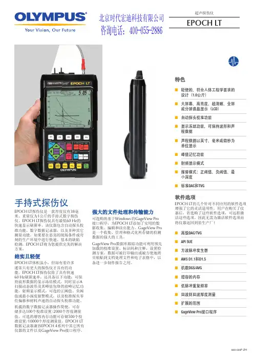
920-020F-ZH超声探伤仪EPOCH LT特色■轻便的、符合人体工程学要求的设计(1.0公斤) ■ 大屏幕、高亮度、超清晰、全屏或分屏液晶显示(LCD ) ■自动探头校准功能■显示冻结功能,可保持波形和声程数据 ■声程数据以英寸、毫米或微秒为单位显示 ■峰值记忆功能 ■射频显示模式■报警模式:正阈值、负阈值、最小深度 ■标准DAC 和TVG软件选项EPOCH LT 的几个针对不同应用的软件选项增强了它的灵活适用性。
用户在购买了仪器后,若选购了这些软件选项,可远程激活这些选项。
因此无需为激活软件选项而将仪器返回到原生产厂! ■高级DAC/TVG ■API 5UE■方波脉冲发生器 ■AWS D1.1和D1.5 ■机载DGS/AVG ■增容的内存 ■低脉冲重复频率 ■回波到回波厚度测量 ■扩展的范围■GageView Pro 接口程序EPOCH LT 探伤仪是一款厚度仅有38毫米、重量仅为1公斤的手持式数字探伤仪。
EPOCH LT 探伤仪具有最低60 Hz 的快速显示刷新率。
该仪器包含自动探头校准功能、数字数据记录器,以及多种其它测量功能。
如果要在恶劣的现场条件或苛刻的生产环境中进行快速、基本的缺陷检测,EPOCH LT 将为您提供完美的解决方案。
结实且轻便EPOCH LT 体积虽小,但却有着许多通常只有更大的探伤仪才具有的功能。
EPOCH LT 探伤仪除了具有快速60 Hz 刷新速率,还具备以下功能:可保持波形数据的显示冻结模式,同时显示A 扫描动态波形及其峰值包络的波峰记忆功能,射频显示模式,可选的正阈值、负阈值或最小深度报警模式,以及校准探头零位偏移和材料声速的自动探头校准功能。
机载的数字数据记录器操作简便,可存储多达100个校准设置/2000个厚度测量值。
可选的增容内存功能可存储500个校准设置/10000个厚度测量值。
EPOCH LT 数据记录器兼容EPOCH 4系列中其它所有仪器的文件以及GageView Pro 接口程序。
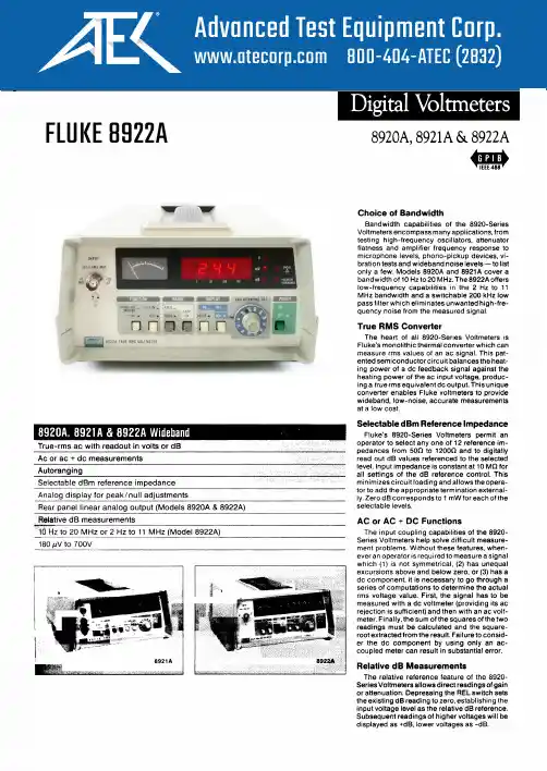
FLUKE 8922A8920A, 8921A & 8922AAutorangingFluke's autoranging feature allows you to carry out your testing without having to change ranges manually. A range can be placed on HOLD or manually stepped up to a higher range. On HOLD, the meter will remain in a given range regardless of changes in input levels. On STEP UP, the meter will increase ranges step-by-step until the switch is released. Peaking/Dipping MeterIn addition to an accurate digital display, all Fluke Voltmeters in the 8920-Series feature an analog meter for peak and null voltage adjustments. The meter indicates O to 100 percent full scale in each range.Linear Analog OutputModels 8920A and 8922A are equipped with a rear panel output for driving X-Y or st d p chart recorders, delivering voltages proportional to the display count. A 2-volt level equals 2000 counts, a 1-volt level equals 1000 counts, etc. This feature is not available on Model 8921A. AccuracyFluke Digital Voltmeters avoid the possibilities for error so common in analog meters. The digital displays eliminate the likelihood of misreading the meter due to viewing angle problems of parallax common with analog meters. Also, the accuracy of 8920-Series Voltmeters is specified as a percent of reading rather than as percent of full scale.Percent of reading accuracy does not degrade for measurements at the low end of a scale. Front panel switching offers a choice of readings in dB or volts.Technical SpecificationsThe a ccuracy s pecifications b elow apply from 9% to 100% of full scale and from 18°C to 28°C for 90 days. For six-month specifications multiply figures by 1.5.AC Accuracy: ± % of voltage reading or ±dB (8920A/8921 A)Range 2Hz 10 H z 20Hz 50Hz 10 kHz 700V200V1%or 0.5%or 20V 0.15dB 0.1 dB 2V Not200mV Speci-5%orlied 0.5dB 2%or 1%or 20 m V 0.25 d B 0.15dB3%or 2%or 2mV0.35dB 0.25dBAC Accuracy: ± % of voltage reading or ±dB(8922A)Range 2Hz 10 H z 20Hz 50Hz 10 k HzFILTER IN I700V200V 1%or•0.15 d B 1%or 0.5%or20V 0.15 d B 0.1 d B2V 5%or200 mV 3%or• 0.5dB0.35dB2%or•0.25dB 2%or 1%or20 mV 0.25 d B 0.15 d B5%or0.5dB5%or• 5%or 3%or 2%or I2 mv0.5 d B .. 0.5dB 0.35 d B 0.25dB• Valid when AC + DC DAMPING is selected andinput has no de components.••Below 2 mV add number of digits (N) to ±5% voltage readings, where N = 5 + mV input. Or, for dBreadings. add N to ±0.5 dB, where N = 0.5 + (mVinput)2AC+DC Accuracy: Add to AC accuracy specifications (above) ±10 digits or ±0.5 dB above 2mV, or ±100 digits or ±5.0 dB below 2 mV. Forde only, add above digits to 50 Hz to 10 kHzspecificationsFunctions: True RMS measurements only. ACor AC+ DC (8920A and 8921 A); AC or AC+ DCwith damping (8922A)Maximum Input: 700V rms or 1 O OOV peak, not toexceed a volt-hertz product of 1 x 10⁸ on anyrangeMaximum Common Mode Voltage8920A and 8922A: 400 mV rms or 600 mVpeak8921A: 500V rms or 700V peakAC Common Mode Rejection: �60 dB at 50 and60 Hz with 1000 unbalanceDC Common Mode Rejection: �100 dB, 1000unbalanceCrest Factor: 7 at full scale, increasing downscale by 7 times the voltage range divided by thevoltage input. Degrades below 10 Hz, annunciated when capability exceeded (8922A only)Input Impedance: 10 MO shunted by <30 pF200kHz 1 MHz 2MHz 10 M Hz 20MHzNot Specified0.7%or0.15 d B3% o r0.35 d B 5%or0.5dB2%or0.25dB 4%or0.4dB I3%or0.35dB200kHz 1 MHz 2MHz 11 MHzFILTER OUTNot Specified0.7%or0.15 d B3%or0.35 d B2%or 5%or0.25 d B 0.5dB4% o r0.4 d BVoltage R11nges: 2 mV, 20 mV, 200 mV, 2V, 20V,200V, 700VRanging: Autoranging with HOLD to defeat a�to•ranging and STEP UP for manual ranging.Ranges up at 2000 counts and ranges down at180 countsDecibel Ranges: In the autorange mode, theinstrument appears as though it has a singlerange spanning 131 dBdBm Reference: Twelve user-selectable impedances are provided to reference a O dBm, 1mW level (500,750,930, 1100, 1240, 1350,1500, 3000, 6000, 9000, 10000, and 12000)(dBV = 10000)Relative dB Reference: A voltage input presentwhen this button is pushed is held as "O dB"reference point. Subsequent readings indicate±deviations from this pointVoltage Resolution: 0.05% of ranges (3½ digits)Decibel Resolution: O.Q1 dB (4½ digits)Typical-3 dB Points: 40 MHz on 20 mV thru 20Vranges and 4 MHz on 2 mV range (8920A/8921 A); 22 MHz on 2 mV to 20V ranges (8922A)Low Pass Filter: Approximately 200 kHz -3 dBpoint, on 8922A onlyReading Rate: 2.5/s or 1 /s with ac + de withdamping (8922A)Autorange Rate: <950 ms or <3.5s with ac + dewith damping (8922A)Response Time: (To rated accuracy) <1.6s or<7s with ac + de with damping (8922A)Readout: Panel-select able for volts or dB,auto•matic decimal point location: analog peaking/dipping meter. " V .. "V .. "dB,,LED Annunciators: Indicate m , ,"REL REF," and "2 MHz MAX" for 2 mV range(8920A and 8921A) and "UNCAL" when crestfactor limitation exceeded (8922A)Overrange: Flashes maximum reading for thatrangeUnderrange: Flashes decimalLinear Analog Output: (8920A and 8922A only)Linear output of 2000 mV de for a 2000-countreadout; ±1.0% relative to display; essentiallyoo output into a �10 kO load; non-isolated, withoutput common same as input common。
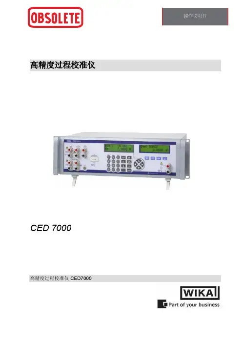
高精度过程校准仪CED 7000高精度过程校准仪 CED7000CED 7000 操作说明书1. 前言 (4)1.1 客户服务 (4)1.2 标准设备 (4)1.3 选件和附件 (4)1.4 拆箱 (4)1.5 安全信息 (5)2. 校准仪说明 (7)2.1 前面板概述 (7)2.2 主要输入/输出端子 (8)2.3 主要输入/输出显示和控制按钮 (9)2.4 隔离输入显示、控制按钮和端子 (11)2.5 后面板 (12)2.6 显示布局 (13)2.7 错误消息 (15)3. 开始使用 (16)4. 主要输入和输出 (16)4.1 直流电压输出 (16)4.2 直流电流输出 (17)4.3 电阻式温度检测器 (RTD) 和电阻测量 (18)4.4 电阻式温度检测器 (RTD) 和电阻源 (19)4.5 电阻式温度检测器 (RTD) 和自定义系数 (20)4.6 标准铂电阻温度计 (SPRT) 系数 (21)4.7 热电偶 (T/C) 测量 (22)4.8 热电偶 (TC) 源 (23)4.9 压力测量 (25)5. 隔离输入 (26)5.1 电压输入 (26)5.2 电流输入 (26)5.3 压力输入 (27)6. 输出设定点 (28)7. 应用笔记 (29)7.1 P/I 变送器 (29)7.2 I/P 变送器 (30)7.3 V/I 变送器 (30)7.4 RTD 测试 (31)7.5 RTD 变送器 (31)7.6 热电偶测试 (32)7.7 热电偶变送器 (32)7.8 RTD 指示器 (33)7.9 精密电流跳闸装置 (33)7.10 I/I 隔离器/变送器 (34)7.11 使用 IBP-2 探头进行精密温度测量 (34)28. 液晶显示屏和远程接口设置程序 (36)9. 远程接口 (36)9.1 简介 (36)9.2 将 RS-232 端口设置为远程控制 (36)9.3 将 IEEE-488 端口设置为远程控制 (37)9.4 在本地操作和远程操作之间切换 (38)9.5 IEEE-488 接口概述 (39)9.6 使用命令 (39)9.7 检查 CED 7000 状态 (43)10. 远程命令 (47)10.1 简介 (47)10.2 按功能命令汇总 (47)10.3 错误代码列表 (49)10.4 远程命令列表 (50)11. 维护 (67)11.1 清洁校准仪 (67)11.2 更换电路熔断器 (67)11.3 更改线路电压 (68)12. 规格 (69)12.1 一般规格 (69)12.2 直流电压规格,输出 (69)12.3 直流电压规格,隔离输入 (70)12.4 直流电流规格,输出 (70)12.5 直流电流规格,隔离输入 (70)12.6 电阻规格,输出 (70)12.7 电阻规格,输入 (70)12.8 热电偶规格,输出和输入 (71)12.9 RTD 和热敏电阻规格,输出 (72)12.10 RTD 和热敏电阻规格,输入 (73)12.11 压力测量规格 (75)13. 担保 (75)31. 前言WIKA CED 7000 校准仪是一种精准的全功能温度、压力和直流校准仪,适用于研发、制造和校准实验室应用场合。
ART-M721 型自动化仪表综合校验仪使用说明书ART-M721 型自动化仪表综合校验仪是一种集数显式电压、电流、频率标准信号源、Pt100铂电阻温度模拟标准信号源、数字式电压、电流、频率测量功能于一体的高精度、高分辨率、多用途的自动化仪表校准仪器。
它具有信号输出和测试功能,可校验以下各类仪表:以模拟量输入输出的传感器、变送器、调节器、记录仪、智能流量积算仪、电/气执行器等常规的工业自动化仪表。
还可以用于校验和整定计算机一系列接口板卡,如电阻板、A/D板、D/A板等。
可广泛应用于石油、化工、冶炼、造纸、发电、仪表行业及科研部门等领域。
其技术性能符合电II 型、电III 型自动化仪表校验标准,工作环境符合GB6587.1-86《电子测量仪器环境试验总纲》中两组仪器的有关规定。
它与国内外同类仪表相比具有以下四大特色:•功能较全,它几乎包括了自动化仪表所有的电信号;精度高、体积小、重量轻,尤其可直接应用于现场,对各种工业过程控制的自动化仪表实施现场调校、检修。
•可同时输出三路有源毫安信号,极大地方便了需多路输入信号仪表(如智能流量积算仪、弯管流量计等)的校验和检修。
•有宽量程的交流工作电压范围(180~260V.AC),能适应工业现场恶劣的工作环境。
•仪表可同时工作在测量和输出状态,有两个四位半LED显示器,每个显示器有四只单位显示灯,分别显示mA、mV、V、KHz。
通过选择可同时显示输出值及其单位和测量值及其单位。
一.功能输出功能:1.有可作为两线制变送器使用的0~25.00V.DC连续可调工作电源,有一路0~199.99mV.DC直流电压信号,可作为各种热电偶的模拟输出信号。
2.具有两路Pt100热电阻模拟器,可输出Pt100铂电阻-50℃、-20℃、-3℃、-8℃、0℃、7℃、11℃、50℃、100℃、150℃、160℃、170℃、190℃、200℃、250℃、300℃的模拟电阻信号,可作温度变送器输入信号使用。
直读式电子比重计DH-300操作说明书请仔细阅读本说明书,以便正确使用。
请妥善保管本说明书,以备不时之需。
东莞市宏拓仪器有限公司-DahoMeter达宏美拓-服务热线:400 830 0646首次使用说明由于机器首次使用、运输、突然断电、重量损失等原因导致零点改变所引起按键无反应、显示OL 、不能正常显示0.00时,请按如下步骤操作,可排除上述现象。
在确定测量台和水中吊篮上的物品已经清空及水中吊篮与水槽没有接触的情况下: 1.关机。
2.长按【C 】键,再开机直至屏幕显示【CAL 】时方可放手。
3. 按【B 】键一次,显示数字【2】。
(如按【B 】键无反应,请重新尝试上述三个步骤,直至屏幕显示对应数字【2】为止)4. 按【A 】键一次 ,显示数字【1】。
5. 按【ZERO 】键一次,显示数字【3】。
6. 再按【ZERO 】键一次,显示数字【3】。
7. 按【C 】键一次,显示数字【5】。
8. 按【ENTER 】键一次,显示【CAL 】。
(若未显示【CAL 】请重复4-7四个步骤)9. 按【C】键一次,显示多位变化的数字。
10. 按【C】键一次,显示一位或者二位会跳动的数字。
11. 在测量台中央位置放上100g砝码。
12. 按【ENTER】键一次,显示【100】。
13. 再按【ENTER】键一次,显示【100.00】。
14. 取下砝码后,重新开机,即可解决上述现象,做正常校正后即可使用。
※注意:在关机前,请将测量台及吊篮中的物品取出。
(如测试样品、网球、抗浮架、玻璃杯等)。
DahoMeter达宏美拓-服务热线:400 830 0646目录1.概述 (5)1.1原理 (5)1.2用途 (5)2.规格参数 (5)3.仪器介绍 (6)3.1 仪器及配件清单说明 (6)3.2按键功能介绍 (7)3.3显示屏介绍 (7)4.安装 (8)4.1安装环境 (8)4.2防风罩安装 (8)4.3仪器安装 (8)5.校正方法 (9)6.其它设定 (9)6.1温度补偿 (9)6.2其它溶液比重值设定 (10)6.3水温密度对照表 (11)7.测试方法 (11)7.1样品重量参考 (11)7.2 固体测量(密度>1) (12)7.3 浮体测量(比重<1) (13)7.4 颗粒测量 (14)7.5测试结果的选择 (15)8.故障排除方法 (15)9.注意事项及保养 (16)9.1 使用前注意事项 (16)9.2 使用时注意事项 (16)9.3 特别注意事项 (16)1.概述1.1原理直读电子比重计DH-300是根据ASTM D297-93、D792-00、D618、D891等标准,采用阿基米德水中置换法原理与现代微电子技术相结合,以实际温度下水的密度为基础,经过两次重量测量分别得出待测样品的质量与体积,从而通过微电脑直接计算出样品之比重。
Pen Meter pH & ORP Users ManualCT-6822Caution●Please read the manual carefully before using the meter.●The glass electrode at the bottom of the pen is fragile, please use it carefully after taking off the protection cap.Any damage may cause the invalid of the electrode.●The duration period of the glass electrode is one year from the date of purchase whether you use it or not,please change the electrode in time.●The electrode can not be used under the dry condition, always soak the electrode into the distilled water orpurified water for 5 – 30 minutes to activate before use.FEATURESSPECIFICATIONSOPERATING INSTRUCTIONPull out the cap before using, Do not Screw it!*Power ON/OFF Feature1. Press ON/OFF key to turn the Meter on and off.2. The Meter will shut off automatically if there is no operation in 5 minutes.*Self- Checking Feature (Executing the function automatically after the meter is power on each time)1. Press the ON/OFF key to turn on the meter, Self- Checking program will be auto-started with Full screen display.2. the type of the meter will be displayed: 6821, then , the meter is ready for use.3. the default mode is pH mode after the date of the manufacture.4. The test mode will be same with the previous use.*pH Mode1. Press the ON/OFF key for 3 seconds, until the “pH”display on the screen.2. Then press CAL to confirm, and the meter is ready to test in pH mode.* ORP Mode1. Press the ON/OFF key for 3 seconds, until the “pH”display on the screen.2. Press HOLD key to select “ORP”on the screen.3. Then press CAL to confirm, and the meter is ready to test in ORP mode.*Backlight Mode1. Press the ON/OFF key for 3 seconds, until the “pH”display on the screen.2. Press HOLD key to select “LED”on the screen.3. Then press CAL to confirm the backlight mode.4. Power off the meter to close the backlight mode.* Hold FeaturePress HOLD to freeze the current reading, and ‘HOLD’ will be appeared on the LCD. Press HOLD again to release the hold mode.*Restore factory defaults1. If the meter is out of order, Press the HOLD key for 3 seconds, until the “CLR”display on the screen, release the HOLD key and the factory setting is ready.2. The meter needs to recalibrate for pH measurement after the factory setting, but can be used directly for ORP measurement.* Automatic temperature compensation (ATC)The product is capable of measuring with automatic temperature compensation when “ATC” displays on the screen. *℃/℉InterchangeableThe default mode is ℃, press CAL key to switch to ℉.* CalibrationpH calibrationPrepare for 4 measuring glasses to calibration, 1 measuring glass for water and 3 measuring glasses for pH buffer solution(pH4.01, pH6.86, pH9.18).Please be aware of the order of the pH buffer solutions:First: pH6.86, second: pH4.01, third: pH9.18Take the pH 6.86 calibration for example:*Overrage ReminderThere will be “1- - .-”on the display if the pH value is under 0 or over 14;There will be “1- - .-”on the display if the ORP value is under -1999mV or over +1999mV;There will be ‘L’ or ‘H’ on the temp. display area if the temperature is under 0℃or over 50℃.*Low Voltage ReminderThe battery sign will be appeared on the display when battery replacement is needed. MAINTENANCEKeep the glass electrode clean, and cover with the protection cap when not use. Be aware of the damage of the electrode when use it. Products should be kept and stored in a cool, dry place that away from direct sunlight.WARRANTYThe meter is warranted to be free for one year from the date of purchase. (Electrode and battery are not included)This warranty covers normal operation and does not cover battery, misuse, abuse, alteration, tampering, neglect, improper maintenance or damage resulting from leaking batteries. Proof of purchase is required for warranty repairs.Warranty is void if the meter has been opened.NOTE1.Please operate the meter Under the guidance of professionals.2.Soak the electrode into the distilled water or purified water for 5 – 30 minutes to activate before use.3.Please use the standard buffer solutions for pH calibration, and operate it by the calibration steps shown above.DO NOT press CAL key in NON calibration mode, it may cause the calibration Error.4.The pH buffer powder should be fully dissolved in water (250ml).5.In calibration mode, the electrode should be submerged in the buffer solution. Especially pay attention to theElectrode fixed collar if it is loosen when calibration, it may cause the buffer solution enter the inside of themeter.How to make pH buffer solutionThere are 3 pH buffer powder supplied with the meter when you buy them, each powder should be Fully dissolved in water(250ml). DO NOT use the metal containers.Take the formulation of pH 6.86 buffer solution for example:1. Put the pH 6.86 buffer material (in the green sachet) in a jar (the volume should be no less than 250ml).2. Fill the jar with 250ml distill water.3. Place a glass stick in the solution, swirling it until the white powder dissolved.4. Store the buffer solution in the cool and dry place. Attach a label on it for further use.5. For the further calibration, Ensure that there is a constant supply of fresh buffer solution in contact with the probe. Discard the solution after use.The way of the formulation of other buffer is same like that . Please mark it clear and prepare to use it for the future.The use of standard buffer:The buffer solutions (250ml) can be used several times by divided into portions which should be kept in a cool and dry place(20℃-25℃). Never reuse the used portion. The electrode should be fully covered by buffer solution when calibration.。
TKR-820维修手册TKR-820维修手册目录:1. 引言1.1 目的1.2 适用范围2. 设备概述2.1 设备说明2.2 技术规格2.3 附件清单3. 安全操作3.1 安全操作指南3.2 安全警示标志3.3 紧急情况处理4. 维修准备4.1 工具和材料清单4.2 维修环境要求4.3 维修前的准备工作5. 维修流程5.1 故障诊断步骤5.2 维修步骤详解6. 维护和保养6.1 常规维护流程6.2 清洁和保养指南6.3 预防性维护计划7. 常见问题解决7.1 故障现象与对应解决方法 7.2 常见故障代码解析7.3 故障排除流程8. 配件更换指南8.1 重要配件更换步骤8.2 配件清单9. 技术支持9.1 售后服务联系方式9.2 技术支持常见问题解答10. 附件10.1 附件A: 设备示意图10.2 附件B: 维修记录表法律名词及注释:1. 保修条款:设备维修过程中应根据维修服务合同中的保修条款执行。
请详细阅读,并遵守相应规定。
2. 责任限制:在维修过程中,为避免设备进一步损坏或带来其他安全隐患,请谨慎操作、使用工具,并遵守相应的操作规程。
3. 法律责任:维修人员在进行维修过程中,需遵守当地法律法规,并承担维修过程中产生的相关法律责任。
4. 知识产权:本文档所涉及的任何图表、图示、文字等内容,均受到相关知识产权法律法规的保护。
未经授权,任何人不得擅自复制、传播或使用。
5. 免责声明:本文档所提供的内容仅供参考,维修人员应根据实际情况综合考虑,并自行判断并采取相应的措施。
对于因使用本文档所导致的任何损失或损害,我们不承担任何责任。
6. 保密条款:维修人员应妥善保管本维修手册,并严格遵守保密条款。
未经授权,不得擅自向第三方透露、公开或使用本文档相关信息。
本文档涉及附件:1. 附件A: 设备示意图2. 附件B: 维修记录表本文所涉及的法律名词及注释:1. 保修条款:关于设备维修和保修服务的相关规定和要求。
多功能测试仪(TC-V2.12k)Multi-function Tester (TC-V2.12k)浩祺电子科技2015年8月Haoqi Electronic Technology Co., Ltd.August 2015目录1综述 (3)1.1本机说明 (3)1.2功能介绍 (3)2操作指引 (4)2.1按键操作定义 (4)2.2开机 (4)2.3测试晶体管 (5)2.4自动校准 (9)2.5测试稳压二极管 (10)2.6红外解码 (10)2.7关机 (10)2.8内置锂电池电压测量 (11)2.9内置锂电池充电 (11)3性能参数 (12)4常见问题 (13)5装箱单 (13)1Overview (14)1.1Introduction (14)1.2Features (14)2Operating Instructions (15)2.1Key operational definitions (15)2.2Power on (16)2.3Detect transistor (16)2.4Selftest (20)2.5Detect Zener diode (21)2.6IR decoder (21)2.7Power off (22)2.8Built-in Li-ion Battery voltage measurement (22)2.9Charging the Battery (23)3Performance Parameters (23)4FAQ (24)5Packing List (24)多功能测试仪(TC-V2.12k)1综述1.1 本机说明① - 160x128 TFT显示屏② - 多功能按键③ - 晶体管测试区④ - 稳压二极管测试区⑤ - 红外接收窗口⑥ - Micro USB充电接口⑦ - 充电指示灯1.2 功能介绍TC-V2.12k是采用TFT图形显示的多功能测试仪。
●晶体管测试仪-自动测量NPN和PNP晶体管、N沟道和P沟道场效应管、二极管(含双二极管)、电阻(含电位器)、电感、电容、可控硅、电池(0.1-4.5V)等元器件-自动测量稳压二极管(0.01-30V)-自动校准功能●红外解码器-支持日立公司编码-红外波形显示-红外接收指示●其他-测量结果采用TFT图形显示-一键操作-自动关机(关机时长可设置)-内置大容量可充电锂电池-锂电池电压检测-支持中英文双语警告:内置锂电池,严禁将测试仪浸入水中、严禁靠近热高温源!警告:为了您的人身安全,请严格遵守锂电池使用规范和注意事项!2操作指引2.1 按键操作定义多功能按键有两种操作:●短按:按下按键不短于10毫秒且在1.5秒内松开按键●长按:按下按键1.5秒以上2.2 开机关机状态下短按多功能按键,测试仪开机并自动进行测量。
e-mail:**************User’s GuideHHT21ALaser TachometerM3942/0303Where Do I Find Everything I Need for Process Measurement and Control?OMEGA…Of Course!Shop online at TEMPERATUREⅪߜThermocouple, RTD & Thermistor Probes, Connectors, Panels & AssembliesⅪߜWire: Thermocouple, RTD & Thermistor ⅪߜCalibrators & Ice Point ReferencesⅪߜRecorders, Controllers & Process Monitors ⅪߜInfrared PyrometersPRESSURE, STRAIN AND FORCEⅪߜTransducers & Strain Gages ⅪߜLoad Cells & Pressure Gages ⅪߜDisplacement Transducers ⅪߜInstrumentation & AccessoriesFLOW/LEVELⅪߜRotameters, Gas Mass Flowmeters & Flow Computers ⅪߜAir Velocity IndicatorsⅪߜTurbine/Paddlewheel Systems ⅪߜTotalizers & Batch ControllerspH/CONDUCTIVITYⅪߜpH Electrodes, Testers & Accessories ⅪߜBenchtop/Laboratory MetersⅪߜControllers, Calibrators, Simulators & Pumps ⅪߜIndustrial pH & Conductivity Equipment DATA ACQUISITIONⅪߜData Acquisition & Engineering Software ⅪߜCommunications-Based Acquisition Systems ⅪߜPlug-in Cards for Apple, IBM & Compatibles ⅪߜDatalogging SystemsⅪߜRecorders, Printers & Plotters HEATERSⅪߜHeating CableⅪߜCartridge & Strip Heaters ⅪߜImmersion & Band Heaters ⅪߜFlexible Heaters ⅪߜLaboratory HeatersENVIRONMENTALMONITORING AND CONTROLⅪߜMetering & Control InstrumentationⅪߜRefractometers ⅪߜPumps & TubingⅪߜAir, Soil & Water MonitorsⅪߜIndustrial Water & Wastewater TreatmentⅪߜpH, Conductivity & Dissolved Oxygen InstrumentsDirect all warranty and repair requests/inquiries to the OMEGA Customer Service Department. BEFORE RETU RNING ANY PRODU CT(S) TO OMEGA, PU RCHASER MU ST OBTAIN AN AU THORIZED RETU RN (AR) NU MBER FROM OMEGA’S CU STOMER SERVICE DEPARTMENT (IN ORDER TO AVOID PROCESSING DELAYS). The assigned AR number should then be marked on the outside of the return package and on any correspondence.The purchaser is responsible for shipping charges, freight, insurance and proper packaging to prevent breakage in transit.FOR WARRANTY RETURNS, please have thefollowing information available BEFOREcontacting OMEGA:1.Purchase Order number under which the productwas PURCHASED,2.Model and serial number of the product underwarranty, and3.Repair instructions and/or specific problemsrelative to the product.FOR NON-WARRANTY REPAIRS,consult OMEGAfor current repair charges. Have the followinginformation available BEFORE contacting OMEGA:1. Purchase Order number to cover the COSTof the repair,2.Model and serial number of the product, and3.Repair instructions and/or specific problemsrelative to the product.OMEGA’s policy is to make running changes, not model changes, whenever an improvement is possible. This affords our customers the latest in technology and engineering.OMEGA is a registered trademark of OMEGA ENGINEERING, INC.© Copyright 2003 OMEGA ENGINEERING, INC. All rights reserved. This document may not be copied, photocopied, reproduced, translated, or reduced to any electronic medium or machine-readable form, in whole or in part, without the prior written consent of OMEGA ENGINEERING, INC.Safeguards and Precautions1.Read and follow all instructions in this manual carefully,and retain this manual for future reference.2.Do not use this instrument in any manner inconsistent with these operating instructions or under any conditions that exceed the environmental specifications stated.3.Making measurements in close proximity to rotating equipment can be dangerous. Keep all loose clothiing and hair away from exposed moving machinery.Properly replace all machinery guards after completing measurement.4.The socket on the front of the instrument is for use with a remote charger. Only use model R-5 (115 Vac)or R-6 (230 Vac) rechargers to charge the instrument.5.The HHT21A has a laser beam light source. Do not view the laser beam directly as it could be hazardous to the eyes. Do not point the laser beam into another person’s eyes. Do not view the laser beam with telescopic devices.6.With exception of replacing the batteries, this instrument is not user serviceable. For technical assistance, contact the sales organization from which you purchased the product.NOTESSPECIFICATIONS ................................................................1OVERVIEW ..........................................................................2OPERATION .........................................................................2USING THE HHT21A WITH A REMOTE OPTICAL SENSOR (HHT20-ROS)........................................................................3CALIBRATION AND SELF-TEST..........................................3BATTERIES ..........................................................................5CLEANING ...........................................................................5of the way. It may also be convenient to keep a spare supply of reflective tape in the free area underneath this cover.The instrument will provide six to eight hours of continuous operation on a single set of batteries, depending on the type used. The instrument is provided with a built-in charging network, which works in conjunction with the optional NiCad batteries. The optional recharger plugs into the single jack located next to the optical lens at the front end of the instrument.Fourteen to sixteen hours is required for a complete recharge. When the battery voltage in the HHT21A is getting low, the display will blink “LO BAT” to indicate that the batteries need to be replaced.NOTE:Only use model R-5B (115 Vac) or R-6B (230 Vac) rechargers with NiCad batteries. Do not attempt to charge non-rechargeable batteries.ALWAYS DISPOSE OF BATTERIES IN A SAFE AND RESPONSIBLE MANNER.CLEANINGTo clean the instrument, wipe with a damp cloth using mild soapy solution.SPECIFICATIONSThis product is designed for indoor or outdoor use under the following conditions (per IEC1010-1):Speed Range: 5 RPM to 100,000 RPM Accuracy:± 1 RPM or .01% of reading Resolution: 1 RPM Display:6-digit 0.45” high liquid crystal Display Update:Twice per secondOn-Target Indication:Target (Bullseye) on lower left of displayOperating Distance:Range:Up to 10 feet [3.1 m] from leading edgeof reflective tapeAngle:Up to 45° from perpendicular to leading edge of reflective tapePower-On Switch:Pistol grip trigger - may be locked on with latchingpush-button for longer duration measurements Auto hold of last measurement for 90 secondsOptical System:Visible laser light sourceWARNING:Do not view the laser beam directly as it could be hazardous to the eyes. Do not point the laser beam into another person’s eyes. Do not view the laser beam with telescopic devices.Time Base:Crystal controlled Power Source: 4 “AA” batteries; Recharger socket provided foroptional rechargeable batteriesRecharger Input:Max input 7.8 Vdc @ 50mA Temperature:41 °F [5 °C] to 104 °F [40 °C]Humidity:Maximum relative humidity 80% for temperatureup to 88 °F [31 °C] decreasing linearly to 50%relative humidity at 104 °F [40 °C]Remote/Internal Switch Internal Optics LensRecharger JackFigure 1 HHT21A-Rwith Optional Remote Sensor (HHT20-ROS)CALIBRATION AND SELF-TESTThe HHT21A SERIES is a crystal controlled digital instrument that requires no calibration. However, the accuracy of the instrument can be checked at any time by aiming it at an old style fluorescent light and observing 7200 ±2RPM. In countries with 50 Hz. power line frequency, the display will read 6000 ±2 RPM.NOTE:The Tachometer will not correctly read on energy-efficient fluorescent lights.BATTERIESThe HHT21A SERIES operates from four ‘AA’ size batteries which are located under the hinged top of the instrument. To access these batteries,grip the tapered cover at the optical lens end of the instrument and pull up.The cover is hinged at the display end of the instrument and pivots fully outDimensions (LxWxH):6.13” x 3.25” x 1.75 “ plus 4.75” handle[155.7 mm x 82.6 mm x 44.5 mm x 120.7 mm] Weight: 1.25 lbs [0.57 kg]OVERVIEWThe HHT21A SERIES combines the accuracy and safety of a non-contact optical tachometer with the convenience and ease of operation of a pistol grip instrument. The instrument provides non-contact measurement of rotational speed to an accuracy of .01% of reading. It reads RPM directly to the nearest RPM, and a ‘on-target’ indicator is provided to verify the instrument is properly aligned on a target and receiving valid information. OPERATIONThe HHT21A measures rotational speed from a single pulse per revolution. This pulse is supplied by marking the rotating shaft with a visible reflective tape target. The HHT21A is equipped with a built-in laser light source providing a bright red beam which is aimed at the reflective tape located on the rotating shaft. The pulse from the reflective tape is received back through a single lens reflex optical system and detected by a photocell inside the instrument. The HHT21A then computes the rotational speed and displays it to a resolution of 1 RPM.To operate the instrument, simply aim it at the reflective tape while holding it at a distance of 1 inch [25.4 mm] to 10 feet [3.1 m] making sure to observe laser safety precautions. Squeeze the pistol grip trigger, and read the indicated speed. The on-target indicator must be on. The display is updated up to twice per second.For longer duration measurements, the trigger latch on the side of the pistol grip handle can be depressed after pulling the trigger, and the instrument may be mounted on the 1/4-20 threaded bushing at the base of the handle.When the trigger is released, the HHT21A will hold the last measurement taken and display it for up 90 seconds.On very small shafts, the HHT21A will work down to a reflective tape size of approximately 1/8 inch [3.2 mm] square. However, with this small tape size, it would be necessary to operate the instrument very close to the rotating shaft and insure it is held steady. For normal operation, a tape size of approximately 1/2 inch [12.7 mm] square or larger is recommended, and on very large diameter shafts or for very high-speed applications, a larger size piece of tape may be required. It is also recommended that the reflective tape be viewed just slightly off the perpendicular. The HHT21A will operate at angles from 0 to 45 degrees, but best results are obtained by aiming the instrument at the reflective tape at approximately a 10 to 20 degree angle. This insures that only pulses from the reflective tape are received by the instrument and minimizes the problem of interference from a highly polished surface or varying ambient lighting.USING THE HHT21A-R WITH A REMOTE OPTICAL SENSOR The HHT21A-R version of the tachometer has a provision for using the optional HHT20-ROS Remote Optical Sensor. In addition to the standard built-in optics of the HHT21A SERIES, a 1/8 inch [3.5 mm] phone jack is provided on the front panel of the Tachometer to accept a remote optical sensor plug. A toggle switch on the optics panel selects internal or remote operation.For applications requiring the remote optical sensor, move the Remote/ Internal switch to the remote position to disable the internal optics of the Tachometer. When the trigger is pulled or latched, the remote optical sensor can be used for measurements. The HHT20-ROS Remote Optical Sensor operates 3 feet [0.9 m] and ±45° from the reflective tape.。
Calibration Technology Starts HereMartel Electronics Corporation introduces a revolution in pressurecalibration technology for the process industries.With the release of its new BetaGauge 330,technicians will have a small,lightweight hand held calibrator that generates pressures up to 150PSIG using a high performance integral electric pump.Before the BetaGauge 330,users had to manually generate pressures with tedious and hard to use manual pumps or use large,heavy and unwieldy boxes with limited portability and limited battery life.The BetaGauge 330has a form factor only slightly larger than Martel’s popular BetaGauge 321and weighs in at a mere 2.5pounds.The housing is contoured to easily fit a technician’s hand with good balance top to bottom.Performance doesn’t stop with the pump.The BetaGauge 330provides ±0.025%of full scale accuracy on its internal,isolated pressure sensor.Temperature compensation on its internal sensor ensures accuracy in field applications.An external pressure module connection supports all 29ranges of BetaPort-P pressure modules foreven greater measurement capabilityContinued on back.General Features.Integrated internal electrically operated pneumatic pump:generates pressure to 150PSI and vacuum to -12PSI (-1to 10Bar,-10to 100kPa).Accuracy to 0.025%FS .Source/measure 4-20mA.Small,rugged compact design operates on eight (8)standard Alkaline AA batteries-Only 8”high x 4”wide x 2-3/8”deep (20cm x 10cm x 6cm)-Lightweight at just 2.5pounds (1.2kg).External pressure module interface supports all29BetaPort-P compatible pressure modules (requires optional BPPA-100module adapter).Pt100RTD input for temperature measurement,accurate to 0.1°C (0.2°F)(measurement only).24V loop power to power device under test .Store and recall up to 5user defined setups.Large graphic style LCD with backlight can be configured to display up to 3variables displayed simultaneously (user controlled).Ideal for gas flow calibration (custody transfer)applications .Pressure displayed in the user’s choice of 19engineering units .Switch test is automatic using internal sensor or external pressure module .IP56Rated.Percent error functionFor more information:-Call us toll free at 800-821-0023or 603-434-1433-Fax us at 603-434-1653-Email us at ********************and ask for a BetaGauge 330Pressure brochure -Or go to our website, and click on BetaGauge 330Hand Held Pressure Calibrator with Integral Electric Pressure Pump BetaGauge 330The new standard of pressure calibrationPatent PendingSpecificationsRangesAvailable Pressure PSIG:-12to 30PSI /-0.8to 2bar (electric pump)-12to 150PSI /-0.8to 10bar (electric pump)-12to 300PSI /-0.8to 20bar (manual pump)mA 0to 24mA,max,load 1000Ohms RTDPt100,-50to 150˚CEngineering Unitspsi,bar,mbar,kPa,kgcm2,cmH2O@4°C,cmH2O@20°C,mH2O@4°C,mH2O@20°C,inH2O@4°C,inH2O@20°C,inH2O@60°F,mmHg@0°C,inHg@0°C,ftH2O@4°C,ftH2O@20°C,ftH2O@60°FInstrument Power Supply 24VDC at 24mA Accuracy Pressure±0.025%of full scale on internal sensor module dependent for external sensorsAdd 0.005%FS/˚C outside of 15to 35˚C mA ±0.015%of reading ±2counts(simulation and measurement)Volts ±0.015%of reading ±2counts(measurement only)Temperature ±0.1°C (0.2°F)(measurement only)(Pt100RTD)GeneralIntegrated internal electrically operated pneumatic pump:generates -12PSI to 150PSI pressure (-0.8to 10Bar,-8to 100kPa)Manual pump version -12to 300PSI /-0.8to 20Bar EnvironmentalOperating Temperature -10°C to +50°C Storage Temperature -20°C to +60°C Power RequirementsBatteryEight (8)standard Alkaline AA batteries Battery Life 300pump cycles to 150PSI minimum1000pump cycles to 30PSIPhysicalDimensions 8”high x 4”wide x 2-3/8”deep(20cm x 10cm x 6cm)Weight 2.5pounds (1.2kg)Connections Pressure:1/8”female NPT Electrical:standard banana jacks RTD:4pin LEMO style External module:6pin LEMO styleIncluded Accessories -NIST traceable calibration certificate,batteries installed,test leads,test hose fittings,user guide,carrying case.Martel Electronics Corporation Distributed by:3Corporate Park Drive,Unit 1Derry,NH 03038Phone:+1(603)434-1433Fax:+1(603)434-1653Copyright 2008Martel Electronics;All trademarks are the property oftheir respective owners.0807R1CD-330BetaGauge 330BETAGAUGE 330Hand Held Pressure Calibrator withIntegral Electric Pressure PumpA Pt100RTD input is provided for temperature measurements accurate to ±0.1°C (0.2°F).In addition,the BetaGauge 330measures and simulates 4-20mA loop current signals.It can measure up to 30VDC.An internal 24VDC Instrument Power Supply supplies power to a transmitter under test.Like its calibrator siblings,the 330displays up to 3calibration values at one time from the choice of internal pressure sensor,external pressure sensor,temperature from the optional RTD probe orelectrical (mA or VDC).The display is a large back lit graphicsstyle LCD that’s easy to read in any lighting condition.The new BetaGauge 330Pressure Calibrator provides a number of convenience features.Switch test can be performed on internal or external pressure input.Percent (%)Error and damping functions are provided.Up to five frequently used setups can be stored and retrieved with one button recall.The compact,rugged design operates on eight (8)standard AA Alkaline batteries.Due to the power saving designs incorporated in the BetaGauge 330,it can perform approximately 300calibration cycles to 150PSI on one set of batteries.The 330comes in 3ranges of 30PSI,150PSI and 300PSI.The 300PSI version uses a manually operated handpump.Like all Martel calibrators,the BetaGauge 330comes from the factory ready to go to work with batteries installed,NIST traceable calibration certificate,test leads,carrying case and user manual.。