Sorption Isotherms and Kinetics of Sediment Phosphorus in a Tropical Reservoir
- 格式:pdf
- 大小:111.90 KB
- 文档页数:6

中文摘要蛋清肽粉吸湿特性及对其品质特性的影响研究本研究隶属于国家十二五技术攻关项目-《食源性功能肽生物制备技术研究》(2012BAD33B03),开展活性肽粉的制备及稳态化保藏研究,重点研究蛋清肽吸湿特性、吸湿过程中水分的迁移分布及吸湿对蛋清肽的品质特性的影响。
本文以蛋清混合肽粉及从中分离、鉴定出来的三条蛋清源寡肽序列:DHTKE、MPDAHL和FFGFN的高纯度肽粉为研究对象,以静态差重饱和盐溶液法(SSS)、动态蒸汽吸附(DVS)、低场核磁共振(LF-NMR)、高效液相色谱(HPLC)、傅里叶中红外光谱(MIR)、差示扫描量热(DSC)、荧光分光光度法等为研究技术手段,创新性地开展了蛋清混合肽粉的吸湿性研究、蛋清源寡肽亲水性及吸湿特性研究、蛋清源寡肽吸湿过程中水分动态迁移分布研究、蛋清源寡肽吸湿对其品质特性的影响等四方面的研究内容,初步揭示了蛋清肽粉的吸湿特性、吸湿规律及吸湿对蛋清肽品质特性的影响,为后期开展蛋清肽稳态化保藏以及极性微环境中功能肽的作用关系等相关研究奠定理论基础。
本研究所获成果如下:(1)在蛋清肽粉的吸湿性研究中,采用SSS法研究了分子量小于1 kDa、1~3 kDa、3~10 kDa及大于10 kDa的蛋清混合肽粉的吸湿性。
构建了简单而拟合度良好的一元二次吸湿模型,绘制蛋清混合肽的吸湿等温线,据此求得蛋清混合肽粉的吸湿速率方程、吸湿初速度、临界相对湿度(CRH)等特征值。
发现大于10 kDa的蛋清肽粉具有最大吸湿初速度0.1051 g/mL;小于1 kDa的蛋清肽粉的吸湿速率最大,吸湿能力最强,其吸湿平衡率理论计算值为31.5%;经计算,分子量1~3 kDa的蛋清肽粉的CRH最低,为61.57%,蛋清混合肽贮藏相对湿度(RH)不得高于此值。
(2)在蛋清源寡肽亲水性及吸湿特性研究中,以从蛋清混合肽吸湿性最强的组分中鉴定出来的三条蛋清源寡肽序列:DHTKE、MPDAHL及FFGFN为研究对象,通过“多肽计算器”及反相HPLC分析了三条蛋清源寡肽序列的净电荷分布、亲水性等信息,发现三条蛋清源寡肽等电点均为弱酸性,其亲水性强弱关系为DHTKE > MPDAHL > FFGFN。

攻博期间的科学研究计划书## Research Plan for Doctoral Studies.Abstract.Over the past few decades, there has been a growing interest in the development of new materials for use in various applications. One of the most promising classes of materials is metal-organic frameworks (MOFs), which are porous crystalline materials constructed from metal ions or clusters and organic linkers. MOFs have been shown to exhibit a wide range of properties, including high surface area, tunable pore size and shape, and high thermal and chemical stability. These properties make MOFs ideal candidates for a variety of applications, such as gas storage, separation, and catalysis.In this research plan, I propose to investigate the synthesis and characterization of novel MOFs for use in gas storage and separation applications. I will use a varietyof synthetic techniques to prepare MOFs with different pore sizes and shapes, and I will characterize their structural and physical properties using a combination of techniques such as X-ray diffraction, gas sorption, and scanning electron microscopy. I will also investigate the performance of these MOFs in gas storage and separation applications, and I will optimize their properties for these applications.The successful completion of this research project will lead to the development of new MOFs with improved properties for gas storage and separation applications. These MOFs could have a significant impact on the fields of energy and environmental science.Research Goals.The goal of this research project is to develop new MOFs with improved properties for gas storage and separation applications. Specifically, I will focus on the following research goals:Synthesize novel MOFs with different pore sizes and shapes.Characterize the structural and physical properties of these MOFs.Investigate the performance of these MOFs in gas storage and separation applications.Optimize the properties of these MOFs for gas storage and separation applications.Research Methodology.I will use a variety of synthetic techniques to prepare MOFs with different pore sizes and shapes. These techniques include solvothermal synthesis, hydrothermal synthesis, and mechanochemical synthesis. I will also use a variety of techniques to characterize the structural and physical properties of these MOFs, including X-ray diffraction, gas sorption, and scanning electron microscopy.To investigate the performance of these MOFs in gas storage and separation applications, I will use a combination of experimental and computational methods. I will measure the gas sorption isotherms of these MOFs for a variety of gases, and I will use these data to calculate their gas storage capacities and selectivities. I will also use computational methods to simulate the gas sorption behavior of these MOFs, and I will use these simulations to gain a better understanding of the mechanisms of gas storage and separation in these materials.Expected Outcomes.The successful completion of this research project will lead to the development of new MOFs with improved properties for gas storage and separation applications. These MOFs could have a significant impact on the fields of energy and environmental science.Specifically, the expected outcomes of this research project include:The synthesis of novel MOFs with different pore sizes and shapes.The characterization of the structural and physical properties of these MOFs.The investigation of the performance of these MOFs in gas storage and separation applications.The optimization of the properties of these MOFs for gas storage and separation applications.## 攻博期间的科学研究计划。

介孔磷酸铌一锅法高效催化木糖制备糠醛李相呈;张宇;夏银江;胡必成;钟霖;王艳芹;卢冠忠【摘要】木糖转化到糠醛一般包括两步:首先在酶、碱或路易斯(L)酸的催化作用下异构化木糖到木酮糖,接下来木酮糖在酸的作用下脱水得到糠醛.针对木糖水相脱水一步制备糠醛,利用十六烷基三甲基溴化铵(CTAB)为模板剂,借助软模板合作策略制备了一种抗水的新型固体酸催化剂,介孔磷酸铌,并利用X射线衍射(XRD)、N2吸脱附、透射电镜(TEM)、氨气程序升温脱附(NH3-TPD)和吡啶吸附傅里叶变换红外(Py-FTIR)光谱对材料的结构和酸性质进行了表征.研究发现介孔磷酸铌不仅具有很高的比表面积(>200 m2·g-1),比较窄的孔径分布(3.5 nm),同时还具有很强的L酸性和布朗斯特(B)酸性.通过L酸催化的木糖异构化为木酮糖/来苏糖和B酸催化的木酮糖/来苏糖进一步脱水得到糠醛,实现了一步由木糖到糠醛的高效转化.为了优化反应条件,考察了水溶液中反应温度、投料质量比及反应时间对木糖转化率和糠醛收率的影响,在最佳的反应条件下,木糖的转化率为96.5%,糠醛的收率达49.8%.进一步地,为了提高收率且易于分离,利用4-甲基-2-戊酮(MIBK)/NaCl水溶液(体积比为7:3)作为反应混合溶剂,使糠醛收率提高到68.4%.%10.3866/PKU.WHXB201207312【期刊名称】《物理化学学报》【年(卷),期】2012(000)010【总页数】6页(P2349-2354)【关键词】介孔磷酸铌;布朗斯特酸;路易斯酸;木糖;糠醛;水相;双相【作者】李相呈;张宇;夏银江;胡必成;钟霖;王艳芹;卢冠忠【作者单位】华东理工大学工业催化研究所,上海200237;华东理工大学工业催化研究所,上海200237;华东理工大学工业催化研究所,上海200237;华东理工大学工业催化研究所,上海200237;华东理工大学工业催化研究所,上海200237;华东理工大学工业催化研究所,上海200237;华东理工大学工业催化研究所,上海200237【正文语种】中文【中图分类】O6431 引言糠醛又称呋喃甲醛,是重要的杂环化合物和有机化工中间体.例如可以通过催化加氢制备戊二醇,1其中1,2-戊二醇是重要的农药中间体——丙环唑的原料,而1,5-戊二醇则是制备高品质树脂的原料.同时糠醛作为重要的生物质平台分子,可以通过Aldol缩合、加氢制备液态燃料,2,3具有广阔的发展前景.目前常通过生物质原料——半纤维素在酸性条件下水解生成木糖,再由木糖脱水环化生成糠醛.木糖脱水环化制备糠醛要经过木糖在路易斯(L)酸或碱催化下异构化到木酮糖和来苏糖(lyxose),再由布朗斯特(B)酸催化木酮糖和来苏糖脱水到糠醛的过程.4例如,Dias等5利用具有L酸位和B酸位的剥离钛酸盐、铌酸盐和钛酸铌盐的纳米薄板作为催化剂,在水和甲苯的双相溶剂中,于160°C下反应4 h,木糖脱水到糠醛的收率为55%.但剥离钛酸盐、铌酸盐和钛酸铌盐纳米薄板的制备过程复杂,且耗时长.Yang等6使用AlCl3·6H2O和NaCl在水与四氢呋喃(THF)双相介质中催化木糖脱水,通过140°C 微波加热,反应45 min后,糠醛的收率为75%.这里AlCl3作为L酸首先催化木糖的异构化反应,然后进一步脱水到糠醛.Davis等7则使用具有L酸位的Sn-Beta分子筛催化葡萄糖得到5-羟甲基糠醛(HMF),在双相体系中,HMF的收率为56%.在该过程中,L酸位用于催化葡萄糖异构化得到果糖,然后在HCl(B酸)的作用中进一步脱水得到HMF.但液体酸催化的反应存在腐蚀设备、难以分离的缺点;而Sn-Beta分子筛在制备过程中要使用HF,反应时需加入HCl,从而给环境造成很大的危害.随着近年来世界各国对可持续发展战略的日益重视,实现环境友好的绿色化工,研究开发新的催化剂成为当前的研究热点.为解决上述问题,固体酸催化剂被引入到生物质转化的催化过程,目前在生物质催化转化中常用的固体酸催化剂可以分为几大类:炭质固体酸催化剂,8-11分子筛催化剂,12-14酸性树脂催化剂15,16和过渡金属氧化物及磷酸盐.17-19铌化合物作为一类新型的催化材料,具有潜在的应用.其中铌酸和磷酸铌具有强酸性和抗水性,在酸性催化中表现出较高活性,可以用于脱水反应、酯化反应、烷基化反应等.20-22例如Hara等23利用Nb2O5·nH2O催化葡萄糖水相脱水生成5-羟甲基糠醛,120°C时,葡萄糖的转化率高达100%,HMF收率为12.1%,活性远高于超高硅H-ZSM-5分子筛和H型丝光沸石等固体酸催化剂.Armaroli和Busca24利用磷酸处理的铌酸作为催化剂催化果糖的脱水制备HMF,HMF选择性高达100%,HMF收率为28.8%,表现出很高的选择性.磷酸铌材料相对于铌酸材料拥有更高的酸强度和酸量,因此本文试图通过表面活性剂组装法来制备出高比表面积的介孔磷酸铌催化剂,系统研究其酸性质,并将其应用于木糖高效转化制备糠醛的反应中,借助于该材料同时拥有的B酸和L酸物种来实现一步法制备糠醛的目的.2 实验部分2.1 实验试剂D-(+)-木糖(生化试剂),磷酸氢二铵(分析纯),五氧化二铌(分析纯),氢氟酸(37%,w),国药集团化学试剂有限公司;十六烷基三甲基溴化铵(CTAB,分析纯),4-甲基2-戊酮(MIBK,分析纯),氯化钠(分析纯),上海凌风化学试剂有限公司.2.2 介孔磷酸铌的制备酒石酸铌的制备见文献.25具体如下:将Nb2O5用氢氟酸溶解后得到NbF5溶液,之后用氨水调节pH至碱性使其完全沉淀,过滤得到水合氧化铌沉淀.将水合氧化铌分散在事先溶解的酒石酸溶液中,加热搅拌待其完全溶解得到可溶性的酒石酸铌溶液,测定浓度后作为铌源使用.介孔磷酸铌材料的制备具体如下:称取1.0 g十六烷基三甲基溴化铵溶解在装有13 mL水的聚丙烯(PP)瓶中并进行搅拌,水浴加热,温度保持在35°C.称取1.31 g(0.01 mol)(NH4)2HPO4溶解于20 mL水,量取预先制备的20 mL 0.5 mol·L-1酒石酸铌溶液,在连续搅拌下,将(NH4)2HPO4和酒石酸铌溶液混合后滴加至上述CTAB 溶液中.在35°C继续搅拌1 h后,将上述溶液转移到带聚四氟乙烯内衬的不锈钢晶化釜中,于160°C老化24 h.自然冷却后经抽滤、去离子水洗涤,50°C干燥过夜后,置于马弗炉中550°C焙烧6 h,即制得介孔磷酸铌.2.3 催化剂表征X射线衍射分析在德国Bruker D8 Focus上进行.透射电镜(TEM)在美国FEI Tecnai F20 s-TWIN电镜上进行.比表面积和孔分布测试采用美国康塔仪器公司NOVA 4200e型全自动比表面积和孔隙度分析仪进行分析测定.样品在180°C下抽真空处理12 h,然后在液氮温度(77 K)下进行吸附,以氮气作为吸附质,测定催化剂的孔结构.BET比表面积在相对压力p/p0=0.05-0.2范围内计算,孔径分布曲线是根据Barrett-Joyner-Halenda(BJH)法依据脱附线数据计算得出,孔体积为相对压力约等于0.975时的数值.吡啶吸附红外(Py-FTIR)光谱分析在美国Nicolet Nexus 670型红外光谱仪上测定.将催化剂粉末(50 mg)本体压片后放入原位池,于真空400°C下预处理2 h,降至室温后进行吡啶吸附至饱和.然后分别于室温,100、200、300、400°C下依次真空脱附30 min后记录红外谱图,以测定样品的酸类型和酸强度.2.4 糠醛的制备及收率的测定准确称取0.5 g木糖与一定量的磷酸铌催化剂放入带温控和搅拌的高压反应釜内,加入10 mL去离子水作为溶剂;封闭高压反应釜,通氮气驱除反应釜内的空气,并保持氮气压力约0.5 MPa以维持液相状态.加热并搅拌,在一定温度下反应一段时间后冷却,取出反应物,离心分离得到产物,进行液相色谱分析(Agilent 1200 series),糠醛测定选用XDC-C18柱(Eclipse USA),木糖检测选用糖分析柱SC-1011(Shodex).3 结果与讨论3.1 催化剂的表征X射线衍射分析表明该材料为无定形结构,元素能谱分析表明该材料的Nb/P质量比约为1,N2吸脱附实验表明该材料具有很高的比表面积.图1给出了介孔磷酸铌的N2吸脱附曲线和孔分布曲线(脱附线计算),可以看出氮气低温吸脱附曲线是典型的第四类吸脱附曲线并且在相对压力为0.4-0.7之间有一个H1迟滞环,这是介孔材料所特有的现象.介孔磷酸铌的比表面积为213.5 m2·g-1,孔体积在0.27 cm3·g-1,平均孔径分布在3.5 nm,从材料的XRD表征(图2A)可以看出该材料是一种无定形的结构,同时未焙烧的材料在小角处有一个较宽的衍射峰,表明具有无序的蠕虫状结构.同时从材料的透射电子显微镜图(图2B)中也可以看到材料存在大量的蠕虫状的介孔结构.综上所述,说明通过上述方法可以制备出大比表面的介孔磷酸铌材料.文献24,26中报道磷酸铌材料是一种良好的固体酸材料,在材料结构表征的基础上,我们又系统研究了材料的酸性质.图3为材料的吡啶红外吸附曲线,从中可以清楚地看到介孔磷酸铌表面同时具有B酸和L酸两种酸物种.图中1450 cm-1处的吸收峰对应于L酸物种吸附吡啶后的特征吸收峰,1540 cm-1处的吸收峰可归结为B酸物种吸附吡啶后的特征吸收峰,而1490 cm-1处的吸收峰为B酸和L酸共同作用下的吸附峰.图1 介孔磷酸铌的氮气吸脱附曲线(a)和孔径分布曲线(b)Fig.1 N2sorption isotherms(a)and pore size distribution(b)of niobium phosphate图2 煅烧后介孔磷酸铌的广角XRD图谱(插图为未焙烧的小角XRD图谱)(A)和透射电子显微镜图(B)Fig.2 Wide-angle XRD pattern of calcined niobium phosphate(inset is the small angle XRD pattern of uncalcined niobium phosphate)(A)and TEM image of calcined niobium phosphate(B)图3 不同真空脱附温度下的介孔磷酸铌的吡啶吸附红外谱图(A)和介孔磷酸铌的氨气程序升温脱附曲线(B)Fig.3 Temperature-dependent pyridine adsorbed IR spectra(A)and NH3-TPD of niobium phosphate(B)L酸和B酸的强度分布可以用不同温度下的吡啶吸附红外来表征,见图3.其中200°C的低温吸附峰对应于弱酸酸位,200-400°C对应于中强酸,而高于400°C的高温峰对应于强酸酸位.可以看出介孔磷酸铌的酸强度在中强酸范围(不管是L酸还是B酸),并且在400°C仍然具有比较强的吸附信号.同时从氨气程序升温脱附曲线中也可以看出,和商业的氢型Beta分子筛相比,磷酸铌材料拥有基本相同的酸总量,其酸强度分布和吡啶红外吸附测试结果基本吻合,表明磷酸铌材料表面拥有大量的中强酸物种,并且也有一定强酸物种.3.2 水相木糖脱水制备糠醛取0.5 g介孔磷酸铌作为催化剂,加入0.5 g木糖,以水做为反应溶剂,在160°C下反应1 h,木糖的转化率达到96.5%,糠醛收率高达49.8%.进一步详细研究了木糖脱水反应中反应温度、投料质量比、反应时间及磷酸铌催化剂循环使用次数对木糖转化率及糠醛收率的影响.3.2.1 反应温度的影响催化剂加入量为0.5 g,木糖0.5 g,水10 mL,反应时间为1 h,在130-180°C范围内得到的木糖转化率和糠醛收率见图4.由图4可知,木糖转化率随着反应温度的升高而增加,糠醛收率随温度的升高先是增大,而后当温度高于160°C后随温度升高糠醛的收率反而降低.这是因为木糖脱水环化反应是吸热过程,温度的增加有利于反应的正向进行,从而导致木糖转化率的提高.但是,反应温度过高会导致糠醛的自聚合,形成可溶性大分子胡敏素,或是在高温下脱水碳化,反而导致糠醛收率降低.因此,最佳反应温度为160°C,木糖转化率为96.5%,糠醛收率为49.8%.图4 反应温度对木糖转化率和糠醛收率的影响Fig.4 Influence of the reaction temperature on conversion of xylose and yield of furfural3.2.2 投料质量比的影响固定其它条件不变,在反应温度为160°C时考察投料质量比的影响,结果见图5.由图5可知,催化剂用量0.5 g,木糖用量0.5 g,即投料质量比为1时,木糖转化率和糠醛收率均为最大,为96.5%和49.8%.当投料质量比增大后,较高的木糖浓度较易导致木糖直接无序脱水后发生碳化,且过量的糠醛会进一步发生自身缩合反应,导致木糖转化率和糠醛收率降低.3.2.3 反应时间的影响固定其它条件不变,考察了反应时间对糠醛收率的影响,见图6.由图6可知,反应时间为0.5 h时,糠醛收率最高,为49.8%,此时木糖转化率为96.5%.木糖转化率随着时间的增加而增加,大约0.5 h时,反应已基本完成.继续延长反应时间会导致较多的副反应发生.图5 底物和催化剂的质量比对木糖转化率和糠醛收率的影响Fig.5 Influence of mass ratio of substrate to catalysis on the conversion of xylose and yield of furfural图6 反应时间对木糖转化率和糠醛收率的影响Fig.6 Influence of reaction time on conversion of xylose and yield of furfural图7 磷酸铌的循环使用效果图Fig.7 Cycle uses of niobium phosphate3.3 双相体系中木糖的催化转化为了便于产物的分离,在其它反应条件相同的条件下,我们又采用4-甲基-2-戊酮(MIBK)/NaCl的水溶液(7:3,V/V)作为双相体系进行了研究.发现与纯水相相比,糠醛的收率大幅上升,增幅近20%,糠醛收率高达68.4%,这是固体酸催化的糠醛最高收率.由于在双相体系中,生成的糠醛可以转移到有机相,避免了糠醛在水相的自聚合;同时加入NaCl改变了两相体系中萃取溶剂的性质,减小了水相中糠醛的浓度,使木糖脱水反应向糠醛方向进行,从而大大提高了糠醛的收率.3.4 催化剂的循环使用催化剂在4-甲基-2-戊酮和水双相体系中进行循环使用效果如图7所示.我们发现随着催化剂循环使用次数的增加,木糖的转化率与糠醛的收率均有一定程度的降低,但使用4次后,糠醛收率仍接近60%,保持了很高的收率.催化剂的部分失活可能与固体酸表面积碳的产生有关,26尤其是在水溶液体系中.4 结论利用十六烷基三甲基溴化铵作为模板剂合成了大比表面积,同时又具有路易酸位和布朗斯特酸位的介孔磷酸铌,并将其成功地应用于一步法催化转化木糖制备糠醛的过程中.研究发现介孔磷酸铌是一种理想的木糖脱水的固体酸催化剂,通过路易斯酸催化把木糖异构化成为木酮糖,进一步通过酸催化的脱水作用把木酮糖转化为糠醛,且能有效循环使用3-4次.以介孔磷酸铌作为固体酸催化剂,在投料质量比为1、反应时间0.5 h、反应温度160°C反应条件下,木糖转化率为96.5%,糠醛收率高达49.8%.进一步研究发现,采用4-甲基-2-戊酮(MIBK)与NaCl水溶液作为反应的两相溶剂,糠醛收率可达68.4%.该催化剂还可以用于葡萄糖的脱水制备5-羟甲基糠醛,该化合物也是生物质利用的一个重要的平台分子,目前该研究工作正在进行中. References(1)Xu,W.J.;Wang,H.F.;Liu,X.H.;Ren,J.W.;Wang,Y.Q.;Lu,mun.2011,47,3924.doi:10.1039/c0cc05775d(2) Huber,G.W.;Chheda,J.N.;Barrett,C.J.;Dumesic,J.A. Science2005,308,1446.doi:10.1126/science.1111166(3)Alonso,D.M.;Bond,J.Q.;Dumesic,J.A.Green Chem.2010,12,1493.doi:10.1039/c004654j(4) Choudhary,V.;Pinar,A.B.;Sandler,S.I.;Vlachos,D.G.; Lobo,R.F.ACS Catal.2011,1,1724.doi:10.1021/cs200461t(5) Dias,A.S.;Lima,S.;Carriazo,D.;Rives,V.;Pillinger,M.;Valente,A.A.J.Catal.2006,224,230.(6)Yang,Y.;Hu,C.W.;Abu-Omar,M.M.ChemSusChem 2012,5,405.doi:10.1002/cssc.201100688(7)Nikolla,E.;Leshkov,Y.R.;Moliner,M.;Davis,M.E.ACSCatal.2011,1,408.doi:10.1021/cs2000544(8)Wang,H.Y.;Zhang,C.B.;He,H.;Wang,L.Acta Phys.-Chim.Sin.2010,26,1873.[王华瑜,张长斌,贺泓,王莲.物理化学学报,2010,26,1873.]doi:10.3866/PKU.WHXB20100721(9) Gong,Y.Y.;Liu,M.;Jia,S.Y.;Feng,J.P.;Song,C.S.;Guo,X. W.Acta Phys.-Chim.Sin.2012,28,686.[公艳艳,刘民,贾松岩,冯建萍,宋春山,郭新闻.物理化学学报,2012,28,686.] doi:10.3866/PKU.WHXB201112292(10)Wang,J.J.;Xu,W.J.;Ren,J.W.;Liu,X.H.;Lu,G.Z.;Wang, Y.Q.GreenChem.2011,13,2678.doi:10.1039/c1gc15306d(11)Zhang,B.H.;Ren,J.W.;Liu,X.H.;Guo,Y.;Guo,Y.L.;Lu,G.Z.;Wang,mun.2010,11,629.doi:10.1016/ j.catcom.2010.01.010 (12) Moreau,C.;Durand,R.;Razigade,S.;Duhamet,J.;Faugeras,P.;Rivalier,P.;Ros,P.;Avignonu,G.Appl.Catal.A 1996,145,211.doi:10.1016/0926-860X(96)00136-6(13) Lourvanij,K.;Rorrer,G.L.Ind.Eng.Chem.Res.1993,32,11.doi:10.1021/ie00013a002(14) Lourvanij,K.;Rorrer,G.L.Appl.Catal.A 1994,109,147.doi: 10.1016/0926-860X(94)85008-9(15)Shimizu,K.I.;Uozumi,R.;Satsuma,mun.2009,10,1849.doi:10.1016/j.catcom.2009.06.012(16) Qi,X.H.;Watanabe,M.;Aida,T.M.;Smith,R.L.J.Ind.Eng.Chem.Res.2008,47,9234.doi:10.1021/ie801016s(17)Watanabe,M.;Aizawa,Y.;Iida,T.;Nishimura,R.;Inomata,H. Appl.Catal.A 2005,295,150.doi:10.1016/j.apcata. 2005.08.007(18)Yan,H.;Yang,Y.;Tong,D.;Xiang,X.;Hu,mun.2009,10,1558.doi:10.1016/j.catcom.2009.04.020(19) Benvenuti,F.;Carlini,C.;Patrono,P.;Galletti,A.M.R.;Sbrana,G.;Massucci,M.A.;Galli,P.Appl.Catal.A 2000,193,147.doi:10.1016/S0926-860X(99)00424-X(20) Nowak,I.;Ziolek,M.Chem.Rev.1999,99,3603.doi:10.1021/ cr9800208(21) Kozo,T.Catal.Today 2003,78,65.doi:10.1016/S0920-5861 (02)00343-7(22) Ziolek,M.Catal.Today 2003,78,47.(23)Nakajima,K.;Baba,Y.;Noma,R.;Kitano,M.;Kondo,J.N.;Hayashi,S.;Hara,M.J.Am.Chem.Soc.2011,133,4224.doi: 10.1021/ja110482r (24)Armaroli,T.;Busca,G.J.Mol.Catal.A:Chem.2000,151,233.doi:10.1016/S1381-1169(99)00248-4(25) Sarkar,A.;Pramanik,P.Microporous Mesoporous Mat.2009,117,580.doi:10.1016/j.micromeso.2008.08.001(26) Paolo,C.;Antonella,G.;Serena,B.;Aline,A.Catal.Today2006,118,373.doi:10.1016/j.cattod.2006.07.024。

Thermoluminescence and Kinetics of Persistent Luminescence of Vacuum-Sintered Tb3+-Doped and Tb3+,Ca2+-Codoped Lu2O3MaterialsJoanna Trojan-Piegza,†Janne Niittykoski,‡Jorma Hölsä,‡and Eugeniusz Zych*,†Faculty of Chemistry,Uni V ersity of Wrocław,14F.Joliot-Curie Street,PL-50-383Wrocław,Poland,and Department of Chemistry,Uni V ersity of Turku,FI-20014Turku,FinlandRecei V ed October25,2007.Re V ised Manuscript Recei V ed December15,2007The properties of green thermoluminescence(TL)and persistent luminescence of Lu2O3:Tb3+and Lu2O3:Tb3+,Ca2+materials sintered in vacuum at1700°C were investigated.The concentration of Tb varied in the range0.1–3mol%,and the Ca content was1mol%.Ca2+codoping enhanced the room temperature persistent luminescence intensity and its duration as well as reduced the number of TL bands for lightly doped materials from four components covering about50–400°C range of temperatures to only one peaking around100°C.The Tb3+,Ca2+(0.1and1mol%,respectively)codoped material showed the most efficient persistent luminescence and TL,originating mainly from the5D4f7F5transition at around545nm,among all the compositions investigated.For this material the persistent luminescence could be observed in the dark for about15h.There are indications that the efficient persistent luminescence of the codoped system is governed by tunneling mechanism,and the trapping centers are postulated to be[Tb Lu×-V O••-2Ca Lu']aggregates.Oxygen vacancies are supposed to serve as traps for free electrons giving F+(e O••)or F(V O×)centers while holes are temporarily immobilized in the vicinity of Tb Lu×giving [Tb Lu×-h•]entities.Alternatively,hole can be trapped in the Ca Lu'site due to its negative net charge, giving[Ca Lu'-h•].Air-sintered specimens did not show any significant persistent luminescence or TL, although they produce quite significant photoluminescence.Also,vacuum sintering at lower temperatures—1600°C and below—was not sufficient to get efficient persistent luminescence.1.Introduction Phosphorescence and afterglow are luminescence pro-cesses with the decay times extending to seconds,minutes, or even hours after ceasing the excitation.Such an afterglow effect is unacceptable in many applications,yet persistent luminescence may be welcome in some others.In cathod-oluminescence,in scintillation and X-ray-stimulated lumi-nescence,in various displays,and in many other uses the persistent luminescence effect cannot be tolerated,and a lot of effort is needed to reduce the afterglow of the material to an acceptable level.1On the other hand,persistent lumines-cence is desirable if one wishes to keep an object visible for an extended time in dark or to store temporarily energy for luminescence extended in time.Such applications include watch dials or glowing road sings.The persistent lumines-cence effect can also be used in much more sophisticated instrumentation such asfiber-optic thermometers,for which the amount of material needed is small but the requirements as to its properties are very demanding and varied and thus hard to fulfill.2Intriguing atfirst,but the persistent lumi-nescence can be useful even to supply light to solar cells in complete darkness.3A persistent luminescence needs the presence of abundant traps able to intercept free carriers,i.e.,electrons,holes,or pairs formed by them(the latter cannot be excluded although are only rarely considered),4and to immobilize them for an appropriately long time.Typically,the persistent lumines-cence is temperature dependent,and freeing a carrier from its trap is thermally stimulated then.However,an intercepted carrier may leave its trap through a tunneling mechanism. This may be a temperature-independent process or a tem-perature-assisted tunneling route,and in such circumstances it may produce persistent luminescence of high intensity.5 For temperature-stimulated processes,if the temperature is too low,the carrier cannot acquire enough energy to escape the trap and,consequently,the carrier cannot either move toward or pass the excessive energy to the luminescent center.On the other hand,if the temperature is too high,the trap is emptied too quickly and the persistent luminescence lasts for too short a time only.It is worth noting that the presence of deep stable traps able to immobilized the carriers*Corresponding author:fax+48-71-3282348,e-mail zych@ wchuwr.chem.uni.wroc.pl.†University of Wrocław.‡University of Turku.(1)Zych, E.Luminescence and Scintillation of Inorganic PhosphorMaterials.In Handbook of Luminescence,Display Materials and De V ices;Nalwa,H.S.,Rohwer,L.S.,Eds.;American Scientific Publishers:Stevenson Ranch,CA,2003;Vol.2,pp251–300.(2)Lizawa,H.A.;Katsumata,T.;Takahashi,J.;Matsunaga,K.;Komuro,S.;Morikawa,T.Re V.Sci.Instrum.2003,74,1344.(3)Qiu,J.;Kawasaki,M.;Tanaka,K.;Shimizugawa,Y.;Hirao,K.J.Phys.Chem.Solids1998,59,1521.(4)Hölsä,J.;Jungner,H.;Lastusaari,M.;Niittykoski,J.J.Alloys Compd.2001,323–324,326.(5)McKeever,S.W.S.In Thermoluminescence of Solids;Cahn,R.W.,Davis, E. A.,Ward,I.M.,Eds.;Cambridge University Press: Cambridge,1985.2252Chem.Mater.2008,20,2252–226110.1021/cm703060c CCC:$40.75 2008American Chemical SocietyPublished on Web02/22/2008permanently at room temperature is exactly what is required for efficient storage phosphors,which have already found important applications as photostimulated materials.6,7 While carrying out straightforward luminescence experi-ments on vacuum-sintered Lu2O3:Tb3+it was noted that after excitation with UV radiation(wavelengths shorter than ca. 330nm)the material exhibited persistent luminescence.8 Depending on the terbium concentration,this effect could easily be seen by the naked eye for at least a few minutes after ceasing the excitation but sometimes for a noticeably longer time.Furthermore,in spite of being kept for one year in dark,the0.1mol%doped vacuum-sintered Lu2O3:Tb3+ material still stored some of the energy acquired previously, and this energy could be released upon stimulation with IR photons or red light.8This material demonstrated a behavior typical for storage phosphors.6The most efficient photo-stimulated green luminescence was obtained under irradiation of the material with647nm light.Photons of980nm wavelength were also able to stimulate the green Tb3+ emission,but this allowed recovering only a fraction of the total energy stored.These results were encouraging enough to initiate a more thorough investigation of the physical processes taking place in the material during and after excitation.This knowledge could be helpful when tailoring the properties of Lu2O3:Tb3+as an efficient energy-storing or persistent luminescent material.One way to tailor the properties of a persistent luminescent material is to introduce potential traps into the phosphor lattice by creating nonstoichiometry.Such an effect is usually achieved by introducing cations or/and anions with a charge different from those of the original constituents of the lattice. Several methods of investigations can be used to study the effect of such dopants.In this work,thermoluminescence was chosen as the main research tool since it has proven to be a very useful means to reveal valuable information about the traps and their role in determining the spectroscopic properties of materials.9–12The present paper summarizes the results of the work concerning the lutetium sesquioxide, Lu2O3,doped with trivalent terbium,Tb3+,as well as codoped with divalent calcium,Ca2+ions.The Kröger-Vink notation of defects13,14was chosen to be used throughout the entire report.It seems to be a good standard allowing to avoid confusions,possible when authors introduce their own ways of naming various defects.2.Materials and ExperimentsThe Tb3+-doped or Tb3+,Ca2+-codoped Lu2O3were prepared in the form of sintered pellets starting from nanocrystalline powders. The Tb3+content was nominally set at0.1,0.5,1,and3mol% with respect to the Lu3+host cation.For the Ca2+-codoped materials,the Ca2+concentration was arbitrarily set at1mol%of the total amount of the tri-and divalent host cations.The nanocrystalline powders were synthesized through the combustion synthesis8,15using the aqueous metal(Lu3+,Tb3+,Ca2+)nitrates and glycine as the reactants.The combustion process was carried out in a furnace preheated up to650°C.The powders were subsequently cold-pressed into pellets of12mm diameter and about 1mm thick under9tons of load and then transferred into a furnace and annealed for5h at1700°C under a reduced pressure of about 5Pa.The heating and cooling rates of the furnace were3°C min-1. The materials were taken out of the furnace once it had cooled to the temperature of200°C or lower.Two additional Lu2O3:Tb,Ca (0.1and1mol%,respectively)specimens were prepared in vacuum at1500and1600°C for comparison.One sample of Lu2O3:Tb3+ (0.1mol%)was prepared by sintering in air and was used as a reference material.Aqueous rare earth nitrates were prepared using appropriate oxides(Lu2O3,99.995%;Tb4O7,99.99%)supplied by Stanford Materials and nitric acid of analytical purity.Calcium nitrate was prepared from CaCO3(99%).The thermoluminescence(TL)experiments were carried out on 60-80mg pieces of the ceramic Lu2O3:Tb3+(,Ca2+)materials.The TL intensity was eventually calculated for a mass unit(in mg)in order to get results easy to compare quantitatively.The thermolu-minescence glow curves were measured with an upgraded RisøTL/ OSL-DA-12thermoluminescence system operating at a linear heating rate of5°C s-1in the temperature range between25and 400°C.The global TL emission from UV to650nm was monitored. Prior to the TL measurements,the materials were exposed to radiation from a combination of the Phillips TL20W/05(emission maximum at360nm)and TL20W/03(420nm)UV lamps. Exposure times were varied from10to120s.In order to monitor the fading of the persistent luminescence,the TL glow curves of the materials were measured with selected delay times(3,30,60, and120min)after the exposure.The decay curves of the persistent luminescence were measured with a FLS920spectrometer from Edinburgh Instruments.Prior to the measurements,the materials were irradiated with UV radiation at270nm for10min.The persistent luminescence was monitored at545nm(with a bandwidth of(10nm),which is the peak intensity of the Tb3+emission from Lu2O3:Tb3+8due to the strong5D4f7F5transition.3.Results and DiscussionThe materials investigated were checked for the structural and phase purity.Only the cubic C-type oxide(lutetia)could be observed in the measured XRD powder patterns.The infrared spectra recorded on powdered materials obtained by grinding the ceramics did not either reveal the presence of any impurities(e.g.,organic residues).All the materials freshly sintered in vacuum had a slightly brownish body color,even if they were taken out of the furnace after cooling them to room temperature in vacuum.The brownish body color is characteristic for the Tb3+-doped Y2O3,too,and has(6)Schweizer,S.Phys.Status Solidi A2001,187,335.(7)Chen,W.Luminescence,Storage Mechanisms,and Applications ofX-Ray Storage Phosphors.In Handbook of Luminescence,Display Materials and De V ices;Nalwa,H.S.,Rohwer,L.S.,Eds.;American Scientific Publishers:Stevenson Ranch,CA,2003;Vol.2,pp1–44.(8)Zych,E.;Trojan-Piegza,J.;Hreniak,D.;Stre¸k,W.J.Appl.Phys.2003,94,1318.(9)Lempicki,A.;Glodo,J.Nucl.Instrum.Methods A1998,416,333.(10)Glodo,J.;Wojtowicz,A.J.J.Alloys Compd.2000,300–301,289.(11)Cooke, D.W.;Bennett, B.L.;McClellan,K.J.;Roper,J.M.;Whittaker,M.T.J.Lumin.2001,92,83.(12)Wojtowicz,A.J.;Glodo,J.;Drozdowski,W.;Przegietka,K.R.J.Lumin.1998,79,275.(13)Kröger,F.A.;Vink,H.H.Relations between the Concentrations ofImperfections in Crystalline Solids.In Solid State Physics;Sietz,F.,Turnbull,D.,Eds.;Academic Press:San Diego,CA,1956.(14)Bridge,F.;Davies,G.;Robertson,J.;Stoneham,A.M.J.Phys.:Condens.Matter1990,2,2875.(15)Zych,E.;Meijerink,A.;de Mello Donega,C.J.Phys.:Condens.Matter2003,15,5145.2253Chem.Mater.,Vol.20,No.6,2008Thermoluminescence of Tb3+,Ca2+-Codoped Lu2O3been explained by the presence of residual Tb 4+ions.16,17This explanation seems to be reasonable also in the case of Lu 2O 3:Tb 3+since sintering in air resulted in materials of similar but much deeper brown color;i.e.,the Tb 4+amount was then higher.The presence of the Tb 4+ion really embedded in the Lu 2O 3lattice would necessitate a charge compensation.In order to maintain electrical neutrality,addition of interstitial oxygen is usually required.The exact position of the additional oxygen may be deduced in a convincing manner from the crystal structure of Lu 2O 3.The crystal structure of the cubic C-type Lu 2O 3(Figure 1)is related to the cubic fluorite (CaF 2)structure with oxygen vacancies.These vacant sites can be capable of accom-modating the additional oxygen ions when tetravalent terbium ions are present.Furthermore,the charge compensation dueto two Tb 4+ions replacing two Lu 3+(2Tb Lu •)for one extrainterstitial O 2-ion (O i '')may lead to the formation of [Tb Lu •-O i ''-Tb Lu •]defect clusters due to electrostatic interac-tions between the O 2-and Tb 4+ions.It is evident from Figure 1that it is possible to obtain quite a few slightly different clusters—considering their symmetry—not just one.On the other hand,these vacant oxygen sites may be occupied by an electron or electrons forming either negatively charged e ′and/or e ′′centers,i.e.,the vacant oxygen sites with one or two trapped electrons,respectively.The electrons would be bound to the Tb 4+ion with electrostatic forces,too,since the electrostatic attraction to Tb 4+is strong due to the high charge/size ratio of this ion.Once again,severalslightly different Tb Lu •-e'(or 2Tb Lu •-e'')defect systems can be anticipated.Once ceramics are formed in vacuum—a moderately reducing atmosphere—the existence of interstitial oxygen is not probable,as has been found for the rare earth cuprates.18In contrast,at high temperatures and with the help of vacuum,formation of yet additional V acant oxygen as well as vacant metal sites should be rather expected due to facilitated migration of atoms toward the surface,from where they may be expelled to vacuum.19,20The scientific literature is abundant with papers reporting such effects occurring at hightemperatures,also for various Tb oxides for which nonsto-ichiometry is rather easily achievable.21–263.1.Thermoluminescence of Tb 3+-Doped Lu 2O 3.The TL glow curves (Figure 2)of the Lu 2O 3materials doped with Tb 3+at various doping levels were first measured to probe the effect of the terbium concentration on the thermally stimulated luminescence of these materials.It is immediately seen that the 0.1and 0.5mol %doped materials possess significantly more complex glow curves when compared to those containing higher amounts,i.e.,1or 3mol %of terbium.The TL glow curves of the materials with low terbium content exhibit three components located at ca.100,200,and 360°C.The two low-temperature bands are clearly structured and are probably doublets.The materials with terbium concentration higher than 0.5mol %show much simpler glow curves,essentially with only one band peaking around 125°C.The glow curves show concentration dependence:with increasing terbium concentration the intensity of the initially dominant high temperature band located at ca.360°C decreases and finally disappears completely.Moreover,the overall TL intensity decreases with increasing terbium content.For the 3mol %terbium-doped material,the TL emission is several orders of magnitude weaker than for ceramics containing 0.1and 0.5mol %of the dopant.The glow curves reveal that there are several traps with rather different depths present in the lightly doped specimens able to intercept electrons and/or holes freed upon the UV excitation.Some of the traps are relatively shallow (100and 125°C)while the others are much deeper (200and 360°C).For the photostimulated phosphor application,the disap-pearance of the high-temperature TL bands is detrimental as is the enhancement of the TL intensity at the low-temperature range.Both the photostimulated and persistent luminescence rely upon storing of the excitation energy for further use—in the case of persistent luminescence immediately after ceasing (or even simultaneously)the irradiation,whereas in the(16)Blasse,G.Prog.Solid State Chem.1988,18,79.(17)Blasse,G.;Grabmaier,B.C.Luminescent Materials ;Springer-Verlag:Berlin,1994.(18)Richard,P.;Riou,G.;Jandl,S.;Poirier,M.;Fournier,P.;Nekvasil,V.;Divis,M.Physica C 2004,408–410,830.(19)Kingery,W.D.;Bowen,H.K.;Uhlmann,D.R.Introduction toCeramics ,2nd ed.;John Wiley &Sons:New York,1976.(20)Aitasalo,T.;Hölsä,J.;Jungner,H.;Lastusaari,M.;Niittykoski,J.J.Phys.Chem.B 2006,110(10),4589.(21)Miller,A.E.;Jelinek,F.J.;Gschneidner,K.A.,Jr.;Gerstein,B.C.J.Chem.Phys.1971,55,2647.(22)Zhang,J.;Kang,Z.C.;Eyring,L.J.Alloys Compd.1993,192,57.(23)Bevan,D.J.M.;Martin,R.L.Z.Anorg.Allg.Chem.1999,625,57.(24)Kang,Z.C.;Eyring,L.J.Alloys Compd.1998,275–277,30.(25)Kang,Z.C.;Eyring,L.J.Alloys Compd.1997,249,206.(26)Nakazawa,E.;Mochida,T.J.Lumin.1997,72–74,236.Figure 1.Schematic presentation of the two six-coordinated R 3+sites in cubic C-type Lu 2O 3.Figure 2.Thermoluminescence glow curves of the vacuum-sintered Lu 2O 3:Tb 3+as a function of the Tb 3+concentration.2254Chem.Mater.,Vol.20,No.6,2008Trojan-Piegza et al.former case only after stimulation by a laser.It can be safely assumed that the energy storage occurs exclusively in electron and hole traps 6,7in the forbidden energy gap of the host.Since both the storing and the electron–hole recombina-tion process 6leading finally to emission are of importance for the understanding of these processes as a whole,the knowledge of the traps present in the materials is crucial in the analysis of the excitation,storage,and release of energy.Some indication as to the type of defects responsible for the carriers trapping in Lu 2O 3:Tb comes from the fact that the persistent luminescence appears only from materials heated at the reducing atmosphere of vacuum and only if the treatment is performed at temperatures around 1700°C.Clearly,certain changes take place in the material when such high-temperature treatment is applied.Looking for these changes two effects,which are probable to happen,should be pointed out.First is the possibility to create vacancies,both metal and oxygen.Formation of such defects is strongly enhanced by the high temperature and vacuum.Both parameters facilitate the mobility of atoms,and those atoms which migrated to the surface may easily be expelled to vacuum,leaving increasing number of vacancies in the host.This was already discussed above.Another effect which is probable to occur upon high-temperature treatment is an aggregation of defects.This may take place since,as was already stated,the high-temperature enhances the migration of the various species present in the material.Thermodynamically,aggregation and clustering of defects—vacancies,impurities,etc.—is usually advanta-geous.Evidently,appropriately high temperature not only increases the population of vacancies but also facilitates aggregation and clustering of the various defects present inthe material.20,27Summarizing,it can be expected that after the high-temperature vacuum treatment cation and anion vacancies in Lu 2O 3:Tb ceramics will be rather abundant,and their distribution may well not be random.Most of all,because of opposite net charges,one should expect that cation and anion vacancies may agglomerate and cluster.The presence of Tb impurity may additionally enhance such aggregation and clustering.20,27This reasoning is especially important for the Tb,Ca-codoped materials analyzed below.The irradiation time has usually a significant effect on the filling of traps provided the trap depths are sufficiently different.This effect can be used to differentiate and identify traps.For the Lu 2O 3materials doped with terbium,the TL glow curves (Figure 3)are strongly irradiation time-depend-ent for each Tb concentration investigated.Yet,the basic differences in the TL glow curves as a function of terbium content are retained.The glow curves reveal the filling sequence of the traps present in the materials by carriers freed upon the impact of UV photons.The most complex sequences are for the lightly doped materials since their glow curve structures were originally more complicated.In general,the shallowest trap (at ca.120°C)is filled most readily.The deeper traps become more active in intercepting the freed carriers once the shallowest trap is already filled to a significant degree,even very close to saturation.Although the shallowest trap corresponding to the lowest temperature TL band is saturated with the present irradiation power and time,the other bands show no saturation of the corresponding traps.Evidently,higher irradiation power and/or time is(27)Clabau,F.;Rocquefelte,X.;Le Mercier,T.;Deniard,P.;Jobic,S.;Whangbo,M.-H.Chem.Mater.2006,18,3212.Figure 3.Thermoluminescence glow curves of the vacuum-sintered Lu 2O 3doped with different Tb 3+amounts as a function of the UV irradiation time.2255Chem.Mater.,Vol.20,No.6,2008Thermoluminescence of Tb 3+,Ca 2+-Codoped Lu 2O 3needed to saturate the traps corresponding to the TL band at ca.200and 360°C.It was proven difficult to separate traps with similar depths by varying the irradiation time,unfortunately.In spite of the fact that the trap structures of the materials containing 1or 3mol %of terbium are uncomplicated due to their rather simple TL glow curves,one can observe that,for the 1mol %doped specimen,the TL band maximum moves from ca.115°C for the shortest irradiation time to ca.140°C for the longest one.For the 3mol %doped material,an opposite shift is observed;i.e.,with increasing irradiation time,the band maximum moves from ca.115to ca.105°C.It seems that in both cases the seemingly lone TL band comprises at least two strongly overlapping components.On the other hand,the slight shift observed may result from different kinetics 5which explanation,however,needs further investigations to be validated.As the first approximation,the evolution of the TL band maxima as a function of the irradiation time for the 3mol %terbium-doped material follows the second-order kinetics.5The interpretation of the experiments presented above reveals that the most efficient thermoluminescence was obtained from the 0.1mol %doped material.The problem with this specific material was,however,that its glow curve consists of several TL bands being significantly apart and covering a broad temperature range,from 50to 450°C.For practical applications,it would be much better if the total TL intensity could be retained,or even be increased,as a single band.For a storage phosphor,the trap(s)should be relatively deep to preclude the thermal release of the intercepted carriers at room temperature,6,7whereas for efficient persistent luminescence,the trap(s)should be rathershallow,corresponding to a TL band at somewhere between 100and 150°C to let the carriers be freed slowly by thermal energy at room temperature after being trapped.4,28,29Taking into account these findings and considerations,it can be concluded that the Lu 2O 3materials doped with Tb 3+fulfill the requirements of neither a good photostimulated (storage)phosphor nor a good persistent luminescence material.There is certainly a need to modify the trap structure of Lu 2O 3:Tb 3+.One of the most frequently used techniques to carry out these modifications is doping of the original material with ions (mainly cations)possessing a charge incompatible with the original cation,in this case the Lu 3+ion.The alkaline earths,Ca 2+,Sr 2+,and Ba 2+,are such cations and,what seems to be important,with no possibility for a change in the charge.These ions have no perturbing energy levels,either.Indeed,some interesting results were obtained for the Tb 3+,Ca 2+-codoped materials to be dealt with in the following sections.3.2.Ca 2+-Codoped Lu 2O 3:Tb 3+.In order to probe the modifications occurring in the trap structure due to the Ca 2+codoping,the TL glow curves of the Tb 3+,Ca 2+-codoped vacuum-sintered Lu 2O 3(Figure 4)were compared with those for the Tb 3+-doped materials.It is immediately seen that the Ca 2+substitution greatly changes the TL properties of all materials.For the two codoped specimens with low terbium content (0.1and 0.5mol %),the glow curves consist essentially of only one,but slightly asymmetric,band peaking(28)Kinoshita,T.;Yamazaki,M.;Kawazoe,H.;Hosono,H.J.Appl.Phys.1999,86,3729.(29)Aitasalo,T.;Deren ´,P.;Hölsä,J.;Junger,H.;Krupa,J.-C.;Lastusaari,M.;Legendziewicz,J.;Niittykoski,J.;Stre ¸k,W.J.Solid State Chem.2003,171,114.Figure parison of the thermoluminescence glow curves of the Lu 2O 3:Tb 3+and Lu 2O 3:Tb 3+,Ca 2+materials sintered in vacuum.2256Chem.Mater.,Vol.20,No.6,2008Trojan-Piegza et al.at120-125°C.The shape of these bands might suggest that they result from a superposition of two components,with the less intense one peaking slightly below100°C.On the other hand,a similar asymmetry could indicate that the kinetics of the process is of thefirst order.5In general,the Ca2+codoping severely suppressed the TL intensity of the Lu2O3:Tb3+,Ca2+materials with the excep-tion of the lowest Tb3+content(0.1mol%).Despite the very simple TL band structure,the Ca2+codoping enhanced the total TL intensity of this material.The Lu2O3:Tb3+,Ca2+ (0.1and1mol%,respectively)codoped material has a slightly higher TL intensity than the sum of all the TL bands of the Ca2+-free material.For the0.5mol%Tb-doped ceramics,the Ca2+codoping reduced the total TL intensity significantly,however.The TL efficiency became even weaker for the1and3mol%Tb-codoped materials,for which the thermoluminescence was almost totally quenched by the Ca2+codoping.Thus,the influence of the Ca2+ codoping on the TL glow curves is indeed very significant, and thefinal goal of the codoping,i.e.,the enhancement of the total TL intensity and the simplification of the TL glow curve,was fully achieved since the Lu2O3:Tb3+,Ca2+(0.1 and1mol%,respectively)codoped material produced the most efficient thermoluminescence among all the composi-tions investigated.Before going to the detailed analysis of the TL glow curves,the structural consequences of the Ca2+codoping should be considered.In fact,the plausible possibilities are very limited.For a six-coordinated site the ionic radii are as follows for Ca2+,Tb3+,and Lu3+:1.000,0.923,and0.861Å,respectively.30Hence,it is unlikely that any significant number of Ca2+ions occupy interstitial positions in the host lattice since the Ca2+ions are relatively large.Clearly, calcium replaces Lu3+in the regular cation site rather than squeezes into an interstitial position deforming strongly the lattice.It is true that the difference between the radii of Ca2+ and Lu3+is close the experimental limit of15%required to yield good solid solubility as stated by the Vegard’s law.31,32 Additionally,it should be expected that the solubility will diminish due to charge and structural incompatibility. Nevertheless,the rather low,1mol%,content of Ca should be quite easily accommodated by the lutetia host lattice without any separation as a new phase.In contrast to the size,the Ca2+codoping creates severe charge compensation problems in the Lu2O3lattice.The most straightforward charge compensation scheme suggests that the lower charge of Ca2+could be compensated by an oxygen vacancy,one for every two Ca2+.Furthermore,since both Tb3+and Ca2+ions are slightly larger than Lu3+,which they replace in the lattice,it is reasonable to expect that high temperature of the ceramics fabrication leads to clustering of both codopants and the oxygen vacancy(V O••)owing to the facilitated migration of these species.19,20Consequently, it is reasonable to postulate that the unavoidable point defects aggregate spatially during the high-temperature sintering forming[Tb Lu×-V O••-2Ca Lu']clusters consisting of Tb3+replacing Lu3+(a neutral defect),a positive O vacancy,and two Ca2+ions replacing Lu3+(each a negative defect). Another possibility for the charge compensation could be that Ca2+codoping stabilizes the tetravalent terbium in the Lu2O3lattice.This effect,if present,should be Ca concentra-tion dependent:more Ca2+should increase the concentration of Tb4+(more numerous Ca Lu'sites should raise the concentration of Tb Lu•),and consequently the materials’brownish color should be more profound.For materials prepared in vacuum,varying the Ca content in the range 0.5–3mol%such an effect was not observed(results are not presented here).On the other hand,for materials treated in air,indeed those with higher Ca content turned much darker.Therefore,this scheme of the charge compensation is rather insignificant for materials prepared in vacuum, which are of our concern.Hence,it is assumed that before irradiation Tb is present in the vacuum sintered ceramics as trivalent rather than tetravalent.This assumption gets further support from EPR spectra(not presented here),which,for the nonirradiated specimens,do not show any signal,which might be associated with the Tb4+ion.It has been shown previously that Tb4+gives a strong EPR spectrum similar to that characteristic for the isoelectronic Gd3+ion.33,34In the light of the considerations presented above,it is proposed that the high-temperature vacuum-sintered ceramics of Lu2O3:Tb3+,Ca2+are rather abundant with the[Tb Lu×-V O••-2Ca Lu']clusters of point defects and that these clusters define the properties of the persistent luminescence of the Tb,Ca-codoped ceramics.In such agglomerates electron freed from Tb3+ion upon UV photons may be easily trapped at the nearby located V O••site,giving e O•(or V O×after trapping of the second electron),while the hole left behind may become intercepted in the vicinity of the activator forming the[Tb Lu×-h•]entity(Hosono35named it[(Tb3+)+]).Holes are much less mobile than electrons,35–37and it is reasonable to expect that these carriers remain in the vicinity of their original Tb ions.Such a trapping scheme may be facilitated if the Ca2+ion is positioned in the nearest vicinity of the Tb dopant,as was postulated above.The net negative charge of Ca Lu'stabilizes the trapped hole.This strongly spatially correlated system is required since without that no hours-lasting persistent luminescence could be expected.Hence, it is postulated that after UV irradiation the energy is stored in electrons and holes trapped in defect clusters giving the following,spatially correlated entity:[(Tb Lu×-h•)-e O•-2Ca Lu'].However,the very weak TL band centered at around360°C(Figure4a)for Lu2O3:Tb3+,Ca2+as well as analogously positioned but much weaker band for the Ca2+free materials (Figures2and3)can be a sign of holes trapped further from Tb3+(holes which overcame the potential barrier and escaped further from their original Tb3+ions)as might be the bands(30)Shannon,R.D.Acta Crystallogr.A1976,32,751.(31)Vegard,L.Z.Phys.1921,5,17.(32)Denton,A.R.;Ashcroft,N.W.Phys.Re V.A1990,43,3162.(33)Trojan-Piegza,J.;Zych,E.;Hreniak,D.;Stre¸k,W.J.Alloys Compd.2004,380,123.(34)Zych,E.;Deren´,P.J.;Stre¸k,W.;Meijerink,A.;Mielcarek,W.;Domagała,K.J.Alloys Compd.2001,323–324,8.(35)Hosono,H.;Kinoshita,T.;Kawazoe,H.;Yamazaki,M.;Yamamoto,Y.;Sawanobori,N.J.Phys.:Condens.Matter1998,10,9541.(36)Skuja,L.J.Non-Cryst.Solids1998,239,16.(37)Kinoshita,T.;Hosono,H.J.Non-Cryst.Solids2000,274,257–263.2257Chem.Mater.,Vol.20,No.6,2008Thermoluminescence of Tb3+,Ca2+-Codoped Lu2O3。

中国环境科学 2021,41(1):199~206 China Environmental Science 镧改性膨润土对底泥内源磷控制效果任琪琪1,唐婉莹1*,殷鹏2,尹洪斌3*(1.南京理工大学化工学院,江苏南京 210094;2.江苏省水资源服务中心,江苏南京 210029;3.中国科学院南京地理与湖泊研究所,江苏南京 210008)摘要:以商业化的锁磷材料—镧改性膨润土(Phoslock®)为对象,研究了Phoslock®对磷的吸附动力学和等温线,同时研究了材料对上覆水体以及底泥内源磷释放的控制效果.结果表明,Phoslock®对磷的吸附可以用Langmuir模型拟合,相关性达到0.96,模型计算磷的最大吸附量为10.4mgP/g,且磷吸附符合拟一级和拟二级动力学模型.室内模拟培养结果表明,当锁磷剂投加剂量为1553g/m2时,70d(好氧17d和厌氧53d)内,对上覆水中的磷酸盐去除率达到90%以上,沉积物内源磷释放削减83.1%,但会引起上覆水体中总氮、氨氮以及硝氮的增加,磷形态分析结果表明,表层(0~2cm)底泥中有超过50%的Mobile-P和Al-P转化为稳定态的Ca-P和Res-P,且控磷效果随着投加量的增加而增加.研究表明,Phoslock®对底泥内源磷具有较好的控制效果,但长期效果需加强研究.关键词:锁磷剂;富营养化控制;底泥内源磷;活性磷中图分类号:X524 文献识标码:A 文章标号:1000-6923(2021)01-0199-08The effect of lanthanum modified bentonite on the control of sediment internal phosphorus loading. R EN Qi-qi1, TANG Wan-yin1*, YIN Peng2, YIN Hong-bin3* (1.School of Chemical Engineering, Nanjing University of Science and Technology, Nanjing 210094, China;2.Jiangsu Water Resources Service Center, Nanjing 210029, China;3.State Key Laboratory of Lake Science and Environment, Nanjing Institute of Geography and Limnology, Chinese Academy of Sciences, People's Republic of China, Nanjing 210008, China). China Environmental Science, 2021,41(1):199~206Abstract:The commercial phosphorus inactivation material-Phoslock® was used to investigate its efficiency for sorption isotherm and kinetics. In addition, the control effects on P concentration in overlying water and sediment internal P release was also investigated. The results indicated that P sorption on Phoslock can be fitted well by Langumiur model with a coefficient of 0.996 and the maximum P sorption capacity was estimated to be 10.6mgP/g. P sorption on phoslock can be fitted well by second-order kinetic model. The results of laboratory incubation indicated that the soluble reactive phosphate in overlying water and sediment internal P release can be reduced by more 90% and 80% respectively with a dosage of 1553g/m3 during seventy day of incubation (17days of aerobic and 53days of anaerobic incubation).Unfortuately, the addition of phoslock can induce an elevation of total nitrogen, ammonium nitrogen and nitrate in overlying water. P fractionation analysis indicated that the addition of phoslock can transform more than 50% of mobile P and Al-P into stable Ca-P and Res-P. The control effects can be increased with the increase of dosage of Phoslock. Overall, the results indicated that Phoslcok can effectively control sediment internal phosphorus loading, but the long-term effects still should be studied further.Key words:phosphorus inactivation materials;lake eutrophication control;sediment internal phosphorus;mobile phosphorus近年来,随着工业和生活质量的不断提高,我国湖泊的富营养化问题日益严重.据调查,我国的磷控制性湖泊占比较大[1].因此,减少磷含量是控制湖泊富营养化的关键[2].湖泊中的磷来源分为外源磷和内源磷,当外源污染得到控制后,赋存在沉积物中的内源磷在水体温度、溶解氧、水动力及季节等环境因子发生变化时,会释放到上覆水中,再次造成水体富营养化[3].相关研究[4]指出,湖泊内源磷的释放主要来自表层0~20cm的沉积物,因此,控制表层沉积物的释放成为控磷的关键.采用一种有效的方法来控制内源磷显得尤为重要.改性黏土矿物材料因其相对较低的成本和迅速改善水质的能力而经常被用于沉积物磷的控制[5].常用的固磷吸附剂有镧改性的沸石[6-7],铝改性的凹凸棒石[8],工业副产品如饮用水残留物[9]或由铁、钙、锆改性的其他矿物磷吸附剂[10].这些磷吸附剂的添加可将活性磷转变为更惰性的稳定磷,从而抑制磷的释放.铝改性材料已经广泛应用于世界上很多湖收稿日期:2020-06-01基金项目:国家自然科学基金资助项目(41977363);中科院交叉团队项目(JCTD-2018-16)* 责任作者, 唐婉莹, 副教授,****************.cn;尹洪斌, 研究员, ***************.cn200 中国环境科学 41卷泊中,在控制内源磷方面取得了良好的效果.然而,由于藻华爆发期会极大地提高富营养化湖泊中上覆水的pH值,在高pH值(>9.50)条件下会增加沉积物中铝的氢氧化物释放出磷的风险[11].一种镧改性膨润土锁磷剂[12](商业名称为Phoslock®)是一种高效的吸附剂,由95%的膨润土和5%的稀土镧组成,在pH值为5~7时,H2PO4-对吸附剂表面具有最大的亲和力.与Al相比,Phoslock®施用时不会改变湖泊水的碱度和pH值,这可能是碱度较低湖泊的更好选择[12].另外,膨润土具有与沉积物相似的密度和颗粒大小,沉降后可以作为沉积物的组分从而限制物理再悬浮或生物扰动[13-14],是一种较为理想的磷钝化剂.为了研究Phoslock®的除磷效果,本研究进行了吸附实验探究其对磷的固定化性能,同时采用模拟室内培养测试Phoslock®在有氧和厌氧条件下控制沉积物内部磷的长期固定效率,以期为其实际应用提供参考.1 材料与方法1.1 水样、沉积物柱样采集与处理实验所用沉积物采集于安徽巢湖(31.700610°N, 117.368350°E),所用采样管为内径8.4cm、高度45cm的有机玻璃管,采集完沉积物样后两端用橡胶塞密封.在同一点位收集200L的湖水,这些沉积物柱状样和收集的水在低温中保存,并在4h内运回实验室.相关研究[4]指出,湖泊内源磷的释放主要来自表层0~20cm的沉积物,调整沉积物柱状样至20cm,上覆水至15cm[15],在进行培养实验之前样品一直保持黑暗状态.培养试验结束后用切板将底泥根据沉积物-水界面的距离分为5层:0~2cm、2~ 4cm、4~6cm、6~8cm、8~10cm,匀浆后自然风干研磨过100目筛备用.1.2吸附实验1.2.1 吸附等温线使用KH2PO4制备磷酸根溶液.称取若干份0.5g的Phoslock®于50mL离心管中,加入不同浓度(1,5,10,20,50,100,200,500,1000mg/L)的磷溶液25mL,磷溶液预先用0.1mol/LH2SO4或0.1mol/L的NaOH调整为pH=7,在180r/min,25℃的恒温摇床中震荡24h,离心后经0.45 μm水系滤膜过滤得上清液,并用于可溶性反应磷酸盐(SRP)分析.磷吸附结果拟合到Langmuir吸附模型,e L emL e1q K CqK C=+(1)Freundlich吸附模型由下式给出:m F enq K C= (2) 式中:q m代表磷吸附剂的最大吸附量,mg/g;K L和K F值表示吸附能力的强弱;C e为达到吸附平衡时溶液中的磷浓度,mg/L;q e表示达到吸附平衡时单位磷吸附剂的饱和吸附量,mg/g;n表示吸附的难易.1.2.2 吸附动力学称取若干份0.5g的Phoslock®于50mL离心管中,分别加入25mL初始磷浓度为0.5,10,50,200,500mg/L的磷溶液,pH值调至7,在180r/min,25℃的恒温摇床中振荡,设置不同时间取出(初始磷浓度为0.5,10,50mg/L分别在10,20,30,60,120,240,360min取出;初始磷浓度为200, 500mg/L分别在0.5,1,2,4,6,10,16,24,48h取出)后分析其上清液可溶性反应磷酸盐(SRP)浓度.用拟一级动力学和拟二级动力学模型来表示吸附过程中吸附量随时间的变化,拟合方程如下:拟一级动力学方程:()1e elog log2.303tkq q q t−=− (3) 拟二级动力学方程:22e e1tt tq k q q=+ (4) 式中:q e和q t分别为吸附平衡和t时刻磷吸附剂的吸附量,mg/g;k1、k2分别为一级、二级吸附速率常数,h-1.1.3 室内长期柱样培养实验1.3.1 样品处理与投加量为了研究好氧和厌氧条件Phoslock®对沉积物内部磷的长期控制效率,进行实验室模拟实验.根据表层沉积物中活性磷(0~5cm)含量和锁磷剂的最大磷吸附量来计算理论投加量,理论投加量的计算式如下:ma bVXSq+= (5)式中:X为理论投加量,g/m2;a是待处理的底泥中活性磷(mobile-P)总含量,g;b是待溶解的湖水中SRP的质量浓度,mg/L;V是待溶解的湖水体积,mL;S是柱状样采样管的底面积,m2;q m是由Langmuir等温吸附方程得到的Phoslock®对磷的理论最大吸附量,mg/g.柱状样表层5cm湿泥中的Mobile-P含量为86mg,已过滤的湖水中TP含量为0.19mg/L,Phoslock®的最大吸附量为10.4mg/g,因此,所需1期任琪琪等:镧改性膨润土对底泥内源磷控制效果 201Phoslock®的1、2倍理论投加量为1553g/m2和3105g/m2.1.3.2 实验搭建及过程室内柱状培养实验分别设置(1)空白对照组:不添加Phoslock®的柱状沉积物;(2) Phoslock®:Mobile-P=100:1(1X,1553g/m2);(3) Phoslock®:Mobile-P=200:1(2X,3106g/m2).每组实验均设置3组平行实验.先用虹吸法将所有柱状样中原先的上覆水缓慢抽出,空白对照组再缓慢注入1L 湖水,而第2,3材料处理组注入1L溶解有磷吸附剂的湖水,保持空白组和处理组的上覆水样一致.实验过程柱状样均放置在恒温培养箱(ILB-008-02型)中,保持温度为20°C,pH=7.实验分为好氧期和厌氧期2个阶段,其中第1~17d为好氧期阶段,第17~70d为厌氧期阶段.在好氧期阶段,所有柱子不加顶塞,以空气作为其氧气来源,并在2~3d内曝气,曝气强度以不扰动界面为宜;好氧实验结束后即刻向柱状样中通入氮气,盖紧顶塞,并且每24h向柱状样内通氮气以保持厌氧状态.每隔72h抽取50mL上覆水用于实验指标的测定,然后沿管壁再缓慢注入50mL的对应点位已过滤湖水;厌氧期阶段结束后,向柱内垂直插入Peeper装置[16-17],48h后取出测定.1.4 样品分析方法1.4.1 水体中氮、磷的测定将抽取的上覆水采用0.45µm的滤膜过滤,滤液中的SRP含量用钼蓝比色法进行测定,氨氮用纳氏试剂光度法[16]测定.用pH 计(雷磁,PHS-3C型)测定未过滤上覆水的pH值,将未过滤的上覆水消解后用钼蓝比色法测其TP含量.1.4.2 间隙水中氨氮、磷酸盐含量及其释放通量的测定本实验通过平衡式间隙水采样技术(Peeper)[17-18]获取沉积物间隙水,其技术属于原位被动采样范畴,基于内外膜的渗透压平衡原理,根据滤膜的特性使沉积物间隙水中一些可溶离子和分子通过滤膜与采样介质进行物质交换达到平衡[19].使用之前用N2曝气24h,然后垂直插入柱状沉积物中,48h后垂直取出装置并记录泥水界面的位置,用清水洗去表面的底泥,然后用移液枪刺穿一层渗透膜取出小室内的溶液置于酶标板中,加入显色剂之后于微孔板振荡器内(QB-9001型)震荡,间隙水中的磷酸盐和氨氮浓度采用分光光度计(Epoch BioTek 型)用微量比色法进行测定.对Peeper各小室中测出的数值即为相应位置沉积物间隙水中磷酸盐和氨氮的浓度,利用Fick第一扩散定律计算磷酸盐和氨氮的通量[19],通量由下式计算得到.()sJ cx xDδϕδ=⎛⎞=⎜⎟⎝⎠(6) 式中:φ指表层沉积物孔隙度;D S是沉积物扩散系数;cxδδ是整个沉积物界面上的孔隙水浓度梯度;J为沉积物-水界面的扩散通量.1.4.3 沉积物的磷形态的测定厌氧期实验结束后,用切板对沉积物进行分层,各层沉积物混合均匀后烘干、研磨过100目筛备用,通过分级提取法[20]测定其磷形态含量,简言之,在每一步提取步骤完成后测其过滤后的PO43-P浓度,即为每步提取液中不同磷形态的浓度,沉积物中的磷含量可以依次提取为(a)NH4Cl-P(Labile-P),(b)BD-P(Fe-P),(c)NaOH-rP(Al-P),(d)NaOH-nrP(Org-P)和(e)HCl-P(Ca-P).最后,残留物沉积物在马弗炉中于550℃灰化2h,然后用1mol/L HCl萃取,作为(f)残留P(Res-P).活性磷(mobile-P)为Labile-P,Fe-P和Org-P之和.2 结果与讨论2.1 吸附研究0200400 600 800246810Qe(mg/g)C e(mg/L)图1 Phosl ock®的等温吸附曲线Fig.1 Adsorption isotherms of P on Phoslock®2.1.1 等温吸附进行磷酸盐吸附等温线实验来研究Phoslock®的最大磷酸盐吸附能力,如表1所示,拟合结果如图1所示,计算出的模型参数列于表2.结果表明,用Langmuir等温线方程,Freundlich方程回归磷酸盐吸附等温线具有相对较高的相关参数. Langmuir方程计算得出的Phoslock®的最大吸附容202 中 国 环 境 科 学 41卷量为10.4mgP/g.镧和铝的组合对水和沉积物中的磷进行双重控制要优于单一金属负载吸附剂.这是因为单一的镧和单一的铝基磷吸附剂无法克服富营养化水中的高浓度有机碳和高pH 值的干扰[21],但是,磷吸附剂中两种元素的组合在高pH 值和高有机碳水中均表现良好.表1 Phosl ock ®等温吸附拟合参数Tabl e 1 Phosl ock ®isothermal adsorption fitting parametersLangmuir 吸附模型 Freundlich 吸附模型 磷吸附剂类型q m (mg/g)k L (L/mg)R 2k F (L/mg) 1/nR 2Phoslock® 10.4111 0.0098 0.9555 0.9972 0.34120.98642.1.2 吸附动力学 结果如图2和表2所示,Phoslock ®在初始磷浓度为0.5,10,200mgP/L 时,对磷的吸附均能很好地符合拟一级动力学和拟二级动力学模型,说明Phoslock ®对磷的吸附是物理吸附和化学吸附同时存在的.0 10 20 30 40 50时间(h)Q e(m g /g )图2 Phosl ock ®对磷的动力学吸附曲线Fig.2 Phosl ock ®kinetic adsorption curve of phosphorus表2 Phosl ock ®的动力学拟合参数 Tabl e 2 Phosl ock ® dynamics fitting parameters拟一级动力学 拟二级动力学初始磷浓度 (mg/L)q e(mg/g) k 1(1/min)R 2q e(mg/g) k 2(g/mg·minR 20.5 0.0242 7.497 0.98820.0248 16.7867 0.929610 0.4957 0.0924 0.98650.5267 2.0755 0.9681200 3.8955 0.13840.99684.6674 0.1505 0.99442.2 锁磷剂长期控磷效果2.2.1 上覆水pH 值变化特征 pH 值是影响沉积物磷循环和湖泊富营养化的重要因素之一,是评价湖泊水体质量的重要指标[22].上覆水pH 值随时间的变化如图3所示.投加锁磷剂后,总体上材料处理组pH 值和空白组相差不大.具体表现为好氧阶段的第1~10d 的pH 值基本无变化,第10~17d 时对照组和处理组pH 值均有所降低,随即进入厌氧阶段后,pH 值在第26d 时达到峰值后渐渐趋于平缓,pH 值均维持在7.2~7.7左右.说明锁磷剂的加入不会对上覆水pH 值造成影响.102030 40 50 6070678910p H 值时间(d)图3 上覆水pH 值随时间的变化Fig.3 Variation of pH value in overlying water with time2.2.2 上覆水水质变化特征 对于好氧期和厌氧期,锁磷剂处理柱状样后上覆水中TP 和SRP 的含量如图4所示,处理组的上覆水TP 和SRP 含量相对于未投加吸附剂的对照组明显降低,说明锁磷剂对水体有显著的控磷效果.在好氧条件下,对照组沉积物上覆水中的TP 和SRP 浓度保持相对恒定,而在无氧条件下,TP 和SRP 的浓度增加很多.相对而言,好氧条件下水柱中TP 浓度是对照沉积物中厌氧条件下水柱中TP 浓度的1.68倍.类似地,对照处理中厌氧条件下上覆水中的平均SRP 浓度是好氧条件下的5.0倍.在厌氧条件下,三价铁被还原为亚铁.因此,铁结合的磷被释放到水柱中.这与前期的研究结果一致[23-25].相反,与有氧和无氧条件相比,投加锁磷剂后的上覆水中SRP 和TP 浓度在有氧和无氧条件下都保持相对较低的水平(<0.3mg/L).这是因为沉积物中的La 结合磷对氧化还原电位变化不敏感,并且在缺氧条件下可以保持稳定.相对而言,与对照沉积物柱状样相比,1X 的Phoslock ®处理可以降低上覆水中82.6%的TP 和96.8%的SRP.并且与对照相比,高剂量的Phoslock ®1期 任琪琪等:镧改性膨润土对底泥内源磷控制效果 203对水柱中TP 和SRP 的控制效果更好.总体来看,锁磷剂对于柱状样水体中的磷有良好的去除效果,且能维持较长一段时间,因此具有较好的应用前景.0 10 20 3040 50 60 70T P 浓度(m g /L )时间(d)0 10 20 3040 50 60 70S R P 浓度(m g /L )时间(d)图4 上覆水TP 和SRP 随时间的变化Fig.4 Variation of TP and SRP in overlying water with time氮作为湖泊中一种重要的营养组分,当环境条件变化时也会改变底泥中氮的释放.上覆水中总氮、氨氮和硝态氮含量在好氧期和厌氧期随时间的变化如图5所示,在好氧期阶段,以总氮浓度为例,对比对照组发现,添加锁磷剂后,上覆水中总氮含量明显升高;随着培养时间越长,处理组上覆水总氮含量呈现出先增大后减小的趋势,在第14d 后和对照组中的总氮含量基本一致,且随着投加量的增大上覆水中总氮含量升高的越多.在厌氧期阶段,处理组中的总氮含量比对照组高,两个不同的处理组中上覆水的总氮含量随着时间均缓慢的增高,然后逐渐趋于稳定,在37d 后处理组始终比空白组中的总氮含量高.与对照沉积物柱状样相比,1X 的Phoslock ®处理在好氧期上覆水中总氮和氨氮相当于空白组增加了2倍和2.3倍,在厌氧期可以增加上覆水中49.0%的总氮和29.2%的氨氮.而在好氧期和厌氧期阶段材料处理组上覆水中的氨氮含量始终高于空白组,硝态氮的变化趋势和总氮的变化趋势有类似的规律.总的来说,添加锁磷剂后会造成柱状样上覆水中的总氮,氨氮和硝态氮含量的增加.有研究[26]指出连续萃取锁磷剂,膨润土基质的Phoslock ®含有氧化还原敏感的铁,当分散在水中时,Phoslock 可能会释放出铵.0102030 40 50 607012345678T N 质量浓度(m g /L )时间(d)102030 40 50 60700.51.01.52.02.53.03.54.04.5时间(d)N O 3-质量浓度(m g /L )0102030 40 50 60700.51.01.52.02.53.03.54.0时间(d)N H 4+质量浓度(m g /L )图5 上覆水TN 、NH 4+和NO 3-随时间的变化 Fig.5 Variation of TN, NH 4+ and NO 3- in overlying waterwith time2.2.3 底泥释放特征 沉积物中的大量可溶解性204 中国环境科学 41卷物质主要以间隙水作为介质通过表面扩散层向上覆水扩散迁移,因此沉积物间隙水中磷酸盐的多寡可以直接地反映出底质环境的优劣.间隙水中的SRP浓度随深度的变化如图6(a)所示,其中深度以“0”作为沉积物-水界面,沉积物-水界面以上用负值表示,沉积物-水界面以下用正值表示.对照组上覆水中的SRP浓度为0.33~0.55mg/L,间隙水中SRP浓度要远大于上覆水中的浓度,且随着深度的增加呈现出先增大后减小的趋势,在深度为2.8cm处达到最大值2.68mg/L,在5cm以后逐渐减小,这也验证了表层沉积物对内源磷的释放贡献较大,是控制内源磷的关键.在材料组中,不管是上覆水还是间隙水中的SRP浓度都要远远低于对照组,且材料的投加量不同SRP浓度的变化也不同,具体表现为随着投加量增大,SRP浓度降低.其中在沉积物-水界面以上,处理组的投加量不会引起上覆水SRP浓度的变化,处理后的SRP质量浓度为0.10~ 0.20mg/L,此处材料处理组中SRP的去除率为63.2%~82.8%;在沉积物-水界面以下,不同的材料组中的SRP浓度都表现出先增大后趋于稳定的趋势,且2X处理组中SRP的质量浓度低于1X处理组,1X 处理组在界面下1.2~2.8cm处的SRP去除率为71.9%~82.3%,2X处理组在界面下1.2~2.8cm处的SRP去除率为81.4%~90.1%.随着深度的增加去除效果略有降低,到5cm去除率仍有38%左右.综上所述,添加材料后可以大大降低上覆水和表层5cm左右间隙水中SRP的含量,且对沉积物-水界面下5~ 8cm仍有去除效果.SRP (mg/L)对照1X 2X1234P通量[mg/(m2⋅d)]深度(cm)图6 间隙水中SRP浓度的垂向变化和磷扩散通量变化Fig.6 Vertical change of SRP concentration and phosphorus diffusion flux in interstitial water 沉积物-水界面之间的磷交换量可以用扩散通量表示,扩散通量越大,则物质交换量越多.选取间隙水中的垂向浓度由菲克第一定律计算出的磷扩散通量如图6(b)所示,结果表明,锁磷剂的加入可以改变磷酸盐在沉积物间隙水中的分布趋势,使其浓度大大降低,穿过沉积物-水界面的磷通量也得到有效降低,同时随着锁磷剂的投加量增大,扩散通量减小.对照组,1X和2X沉积物中的磷释放通量分别为3.7;0.63和0.19mg/(m2⋅d),与对照组相比,分别从1X和2X处理组中减少了83.1%,94.9%的磷通量.综上所述,锁磷剂的添加会明显降低磷的扩散通量.2.2.4 底泥磷形态变化特征经过70d的室内培养,对照组和处理组沉积物的磷组分如图7所示,结果表明,在对照沉积物中的所有沉积物层中,NaOH-rP(Al-P)是TP的主要部分(51.4~58.9%),活性磷的含量(Labile-P,Fe-P和Org-P的总和)占总磷的20.0~28.9%.沉积物中的这3种磷被认为是磷的活泼形式,当环境条件发生改变时最容易从沉积物中释放出来[25-27].例如,Fe-P和Org-P的一部分最有可能在缺氧条件下和微生物活动期间从沉积物中释放出来,1期 任琪琪等:镧改性膨润土对底泥内源磷控制效果 205因此,Fe -P 和Org -P 可以增加上覆水中的TP 浓度[28-29].原位失活的目的是将磷的活泼形式(Labile -P,Fe -P 和Org -P)转移为惰性形式,与Fe -P 和Org -P 不同,Ca -P 和Res -P 等2个惰性磷形态通常稳定且生物利用度很低[30].投加锁磷剂可以对表层沉积物中的活性磷含量起到大大得削减作用,达到有效的控磷效果.对于表层0~2cm 的沉积物,1X 、2X 处理组沉积物中活性磷的含量分别降低了59.4%,62.7%.对于表层2~4cm 的沉积物,1X 、2X 处理组沉积物中活性磷的含量分别降低了29.6%,29.4%.随着深度的增加,Al -P 在部分条件下有可能会释放出来,有被生物利用的可能性.对比发现,添加材料的处理组沉积物中的Al -P 都有部分程度的削减,比对照组降低了超过30%的Al -P 含量.另外,由于La 3+和Al 3+与沉积物中可移动性P 的反应,观察发现添加Phoslock ®磷吸附剂可以增加Ca -P 和Res -P.这两种惰性P(Ca -P 和Res -P)的双重增加有利于富营养化湖泊的沉积物磷的长期控制[31].具体表现为:表层0~2cm 的沉积物,1X 处理组沉积物中Ca -P 的含量是对照组的4.02倍,Res -P 含量增加了36.5%.对于4~10cm 的沉积物,处理组对各种磷形态对比对照组并没有很明显的变化,可能是由于柱状样中底栖动物较少,不能通过生物的蠕动作用将磷吸附剂向深层沉积物渗透.综上所述,投加理论剂量的Phoslock ®对表层沉积物中的活性磷起到大大削减作用,能提高稳定结合态磷,对固定沉积物中活性磷起到积极作用.Res-PCa-PAl-PMobile-PX2磷含量(mg/kg) 深度(c m )深度(c m )深度(c m )图7 Phosl ock ®对沉积物中磷形态的影响Fig.7 Phosl ock ®'s effect on phosphorus forms in sediments3 结论3.1 根据Langmuir 模型计算得出,Phoslock ®的最大磷吸附量为10.4mgP/g,且其对磷的吸附均能较好符合拟一级动力学和拟二级动力学模型,说明其对磷的吸附是物理吸附和化学吸附同时存在的. 3.2 室内长周期模拟实验表明(17d 好氧,53d 厌氧),Phoslock ®显著降低上覆水总磷以及磷酸根的浓度,与对照沉积物柱状样相比,单倍理论投加量可以降低上覆水中82.6%的TP 和96.8%的SRP,但锁磷剂的添加会造成上覆水中的总氮、氨氮和硝态氮含量的增加.3.3 Phoslock ®的添加可以显著降低间隙水中磷酸根的浓度,与对照相比,单倍和双倍的理论投加量对沉积物-水界面磷的释放削减率分别为83.1%和94.9%.3.4 锁磷剂的添加可将底泥中活性磷和铝磷转化为稳定的钙磷和残渣态磷.单倍和双倍的投加量可对表层底泥中(0~2cm)活性磷削减比例分别达59.4%和62.7%,与对照相比,底泥中的钙磷可增加2倍和3倍.参考文献:[1] 金相灿,屠清瑛.湖泊富营养化调查规范(第二版) [M]. 北京:中国环境科学出版社, 1990,30-35.Jin X C, Tu Q Y. Specification for lake eutrophication investigation (Second edition) [M]. Beijing: China Environmental Science Press, 1990:30-35.[2] 陈镜伊.金属盐改性热处理凹土对水体及底泥磷钝化效果的影响[D]. 南京:南京理工大学, 2018.Chen J Y. Inactivation effects of phosphorus in water and sediment bymetal salt modified and thermal treated attapulgite [D]. NanJing: Nanjing University of Science and Technology, 2018.[3] Wang L Q, Liang T. Distribution patterns and dynamics of phosphorusforms in the overlying water and sediment of Dongting Lake [J]. Journal of Great Lakes Research, 2016,42(3):565-570.[4] Kong M, Yin H B, Wu Y, et al. Influence of thermal treatment on thephosphorus sorption capacity of natural calcium -rich clay minerals [J]. Journal of Environmental Sciences, 2013,33(12):3211-3218.[5] Spears B M, Maberly S C, Pan G, et al. Geo -engineering in lakes: Acrisis of confidence? [J]. Environmental Science & Technology, 2014, 48(17):9977-9979.[6] Lin J, He S, Zhang H, et al. Effect of zirconium -modified zeoliteaddition on phosphorus mobilization in sediments [J]. Science of the Total Environment, 2019,646(PT.1-1660):144-157.[7] Wang Z, Lu S, Wu D, et al. Control of internal phosphorus loading in206 中国环境科学 41卷eutrophic lakes using lanthanum-modified zeolite [J]. Chemical Engineering Journal, 2017,327:505-513.[8] Yin H B, Ren C, Li W. Introducing hydrate aluminum into porousthermally-treated calcium-rich attapulgite to enhance its phosphorus sorption capacity for sediment internal loading management [J].Chemical Engineering Journal, 2018,348:704-712.[9] Wang C, Wu Y, Wang Y, et al. Lanthanum-modified drinking watertreatment residue for initial rapid and long-term equilibrium phosphorus immobilization to control eutrophication [J]. Water Research, 2018:173-183.[10] Douglas G B, Hamilton D P, Robb M S, et al. Guiding principles forthe development and application of solid-phase phosphorus adsorbents for freshwater ecosystems [J]. Aquatic Ecology, 2016,50(3):385-405. [11] Rydin E, Huser B, Welch E B. Amount of phosphorus inactivated byalum treatments in Washington lakes [J]. Limnology & Oceanography, 2000,45(1):226-230.[12] Haghseresht F, Wang S, Do D D. A novel lanthanum-modifiedbentonite, Phoslock®, for phosphate removal from wastewaters [J].Applied Clay Science, 2009,46(4):0-375.[13] Diego C, K arin F, Marziali, et al. Eutrophication management insurface waters using lanthanum modified bentonite: A review [J].Water research, 2016:197-203.[14] 刘新,王秀,赵珍,等.风浪扰动对底泥内源磷钝化效果的影响[J]. 中国环境科学, 2017,37(8):3064-3071.Liu X, Wang X, Zhao Z, et al. Effect of wind and wave disturbance on passivation of internal phosphorus in sediment [J]. 2017,37(8):3064- 3071.[15] Reitzel K, Lotter S, Dubke M, et al. Effects of Phoslock treatment andchironomids on the exchange of nutrients between sediment and water [J]. Hydrobiologia, 2013,703(1):189-202.[16] 国家环保局本书编委会.水和废水监测分析方法 [M]. 中国环境科学出版社, 1989:35-40.National Environmental Protection Agency Book Editing Committee.Water and wastewater monitoring and analysis methods [M]. China Environmental Science Press, 1989:35-40.[17] Xu D, Wu W, Ding S, et al. A high-resolution dialysis technique forrapid determination of dissolved reactive phosphate and ferrous iron in pore water of sediments [J]. Science of the Total Environment, 2012,421-422:245-252.[18] Raymond, Hesslein H. An in situ sampler for close interval pore waterstudies1 [J]. Limnology and Oceanography, 1976,21(6).[19] Ding S , Sun Q, Xu D. Development of the DET technique forhigh-resolution determination of soluble reactive phosphate profiles in sediment pore waters [J]. International journal of Environmental Analytical Chemistry, 2010,90(14/15):1130-1138. [20] William J U, Robert C A. Diffusion coefficients in nearshore marinesediments1 [J]. Limnology and Oceanography, 1982,35(7).[21] Rydin E. Potentially mobile phosphorus in Lake Erken sediment [J].Water Research, 2000,34(7):2037-2042.[22] Yin H B, Du Y, K ong M, et al. Interactions of riverine suspendedparticulate matter with phosphorus inactivation agents across sediment-water interface and the implications for eutrophic lake restoration [J]. Chemical Engineering Journal, 2017,327:150-161. [23] 杨秀敏,任广萌,李立新,等.土壤pH值对重金属形态的影响及其相关性研究 [J]. 中国矿业, 2017,26(6):79-83.Yang X M, Ren G M, Li L X, et al. Effect of pH value on heavy metals form of soil and their relationship [J]. China Mining Magazine, 2017,26(6):79-83.[24] Fuchs E, Funes A, Saar K, et al. Evaluation of dried amorphous ferrichydroxide CFH-12® as agent for binding bioavailable phosphorus in lake sediments [J]. Science of the Total Environment, 2018,628-629: 990-996.[25] Nürnberg G K, Fischer R, Paterson A M. Reduced phosphorusretention by anoxic bottom sediments after the remediation of an industrial acidified lake area: Indications from P, Al, and Fe sediment fractions [J]. Science of the Total Environment, 2018,626:412-422. [26] Hupfer M, Jordan S, Herzog C, et al. Chironomid larvae enhancephosphorus burial in lake sediments: Insights from long-term and short-term experiments [J]. Science of the Total Environment, 2019, 663:254-264.[27] Reitzel K, Lotter S, Dubke M, et al. Effects of Phoslock treatment andchironomids on the exchange of nutrients between sediment and water [J]. Hydrobiologia, 2013,703(1):189-202.[28] Funes, A, Martinez, et al. Determining major factors controllingphosphorus removal by promising adsorbents used for lake restoration:A linear mixed model approach [J]. Water Research, 2018,141:377-386.[29] Upreti K, Maiti K, Victor H, et al. Microbial mediated sedimentaryphosphorus mobilization in emerging and eroding wetlands of coastal Louisiana [J]. Science of the Total Environment, 2019,651:122-133. [30] Huser, Brian J, Egemose, et al. Longevity and effectiveness ofaluminum addition to reduce sediment phosphorus release and restore lake water quality [J]. Water Research, 2016,97:122-132.[31] Xu R, Zhang M, Robert J G, et al. Enhanced phosphorus locking bynovel lanthanum/aluminum–hydroxide composite: Implications for eutrophication control [J]. Environmental Science and Technology, 2017,51(6):3418-3425.作者简介:任琪琪(1995-),女,安徽六安人,南京理工大学硕士研究生,主要从事水环境修复材料的研究.。


谷物湿热平衡新模型及热力学特性的研究陈思羽;吴文福;李兴军;吴子丹;张亚秋;张忠杰;韩峰【摘要】建立谷物平衡水分与相对湿度在不同温度下的关系模型,并利用小麦、玉米、水稻、大米的静态平衡试验数据进行拟合.结果表明,该方程适合描述小麦、玉米、水稻、大米的等温线,可直接求解出谷物的平衡水分.另外,根据所建立的模型,预测了不同温度条件下的安全储藏水分,并对谷物的热力学性能进行了分析:吸着等热值随着平衡水分值的减小而增加,解吸等热值增加更为显著;解吸和吸附过程中吸着等热值均高于水汽化潜热;平衡水分大于25%后,吸着等热值趋于稳定,与汽化潜热值接近;根据分析所得数据,拟合了小麦、稻谷、玉米解吸与吸附过程的吸着等热曲线回归方程,为以能量化的观念实施粮仓作业管理,实现高效、合理、节能储粮提供了有利依据.【期刊名称】《中国粮油学报》【年(卷),期】2016(031)003【总页数】5页(P110-114)【关键词】谷物;吸着等温线;数学模型;热力学性质【作者】陈思羽;吴文福;李兴军;吴子丹;张亚秋;张忠杰;韩峰【作者单位】吉林大学生物与农业工程学院,长春130022;佳木斯大学机械工程学院,佳木斯154007;吉林大学生物与农业工程学院,长春130022;国家粮食局科学研究院,北京100037;国家粮食局科学研究院,北京100037;吉林大学生物与农业工程学院,长春130022;国家粮食局科学研究院,北京100037;吉林大学生物与农业工程学院,长春130022【正文语种】中文【中图分类】TS210.1谷物在一定温度、湿度条件下一段时间后,水分不再发生变动,此时水分为谷物的平衡水分。
Henderson方程[1-2],Chung-Pfost方程[3], Halsey方程[4],修正Oswin方程[5], 修正GAB方程[6]等经典方程都能预测不同温度条件下,水分活度与平衡水分关系。
国内外学者通过经典方程对单一种类谷物的等温线进行拟合[7-8],但单一种类的等温线方程和参数仅适合对应谷物收获后的干燥和储藏通风操作,不同种类谷物的等温线则差别较大。

Journal of Hazardous Materials B137(2006)352–358Preparation and sorption properties of porous materialsfrom refuse paper and plastic fuel(RPF)Z.Kadirova1,Y.Kameshima,A.Nakajima,K.Okada∗Department of Metallurgy and Ceramics Science,Tokyo Institute of Technology,O-okayama,Meguro,Tokyo152-8552,JapanReceived16December2005;received in revised form1February2006;accepted10February2006Available online6March2006AbstractPorous materials consisting of activated carbon and amorphous CaO–Al2O3–SiO2(CAS)compound were prepared from refuse paper and plastic fuel(RPF),(a mixture of old paper and plastic)by carbonizing and/or activating treatments.Samples formed by chemical activation using K2CO3showed a high specific surface area(S BET)of1330m2/g but a lower ash content due to being washed after activation.By contrast,samples prepared by physical activation using steam showed rather lower S BET(510m2/g)due to higher ash contents.The physically activated samples showed much higher uptake properties for Ni2+(a representative heavy metal)and phosphate ions(a representative of a harmful oxyanion)than the chemically activated samples because of the higher content of amorphous CAS in the former samples.By contrast,the chemically activated samples showed higher uptake for methylene blue(MB,a representative organic material)than the physically activated samples because of the higher activated carbon content of higher surface area.Although differences in the sorption properties for Ni2+,phosphate ion and MB were found between the physically and chemically activated samples,both samples show excellent multiple sorption properties for cation–anion combinations and inorganic–organic sorbents.©2006Elsevier B.V.All rights reserved.Keywords:RPF;Activation;Porous material;Multiple sorption;Activated carbon;CaO–Al2O3–SiO21.IntroductionIncreasing industrial production and expansion of human activity has produced increasing amounts of waste matter and the spread of environmental pollution in the world.Although a high percentage of paper is being recycled,large amounts of old paper and paper sludge are still available due to the limitation in the amount already being recycled.Only a part of the waste is reused as raw material for cement but most is burned to paper sludge ash and landfilled.One of the new approaches for reuse of paper waste is to form refuse paper and plastic fuel(RPF)[1],which is a mixture of old paper and plastic.The mixing ratio of paper and plastic in RPF ranges from3:7to7:3and the resulting RPF has the fol-lowing properties;bulk density0.36–0.45g/cm3,carbon content 65–56mass%,ash content4.2–6.3mass%and heat of combus-∗Corresponding author.Tel.:+81357342524;fax:+81357343355.E-mail address:kokada@ceram.titech.ac.jp(K.Okada).1Present address:Institute of General and Inorganic Chemistry Academy of Sciences,Abdullaev Street77a,Tashkent700170,Uzbekistan.tion30–20kJ/g.To avoid generation of dioxins by burning the RPF,the plastics used in RPF are restricted to those which do not contain chlorine.Since paper contains cellulosefibers as its main constituent, activated carbon can be prepared from it[2–4].Shimada et al.[2]prepared raw material for activated carbon by mixing and hot forming old newspaper with phenol resin,and produced activated carbon by physical activation using steam.These acti-vated carbons had specific surface areas of about1000m2/g and adsorption properties for I2(1300mg/g)and methylene blue (330mg/g)similar to those of commercial activated carbons. By contrast,we have prepared activated carbon by chemical and physical activation using old paper only[3,4].The acti-vated carbons prepared by chemical activation using K2CO3 had high specific surface areas of about1700m2/g and adsorp-tion properties for water vapor(1000ml/g)and methylene blue (390mg/g),rather higher than those of commercial activated carbons.The activated carbons prepared by physical activa-tion using steam maintained the original paper shape though the porous and adsorption properties were lower than those prepared by chemical activation.One of the reasons for the0304-3894/$–see front matter©2006Elsevier B.V.All rights reserved. doi:10.1016/j.jhazmat.2006.02.008Z.Kadirova et al./Journal of Hazardous Materials B137(2006)352–358353 lower porous properties of the physically activated carbons com-pared with the chemically activated carbons is a higher ashcontent,originating from inorganicfillers and coating materi-als,i.e.kaolinite(Al2Si2O5(OH)4),limestone(CaCO3)and talc(Mg3Si4O10(OH)2).Although paper contains only a small amount of inorganicmatter,its content is more concentrated in the paper sludge.Thus,we have prepared an amorphous CaO–Al2O3–SiO2com-pound by calcining paper sludge at500–1000◦C[5]becausesuch compounds(e.g.CaAl2Si2O8)prepared from solid-statereaction of kaolinite and CaCO3show good uptake properties forvarious heavy metal ions[6].The amorphous CaO–Al2O3–SiO2compound was found to have good uptake properties for not onlyheavy metal cations but also for eutrophication related ions,i.e.phosphate and ammonium ions[5].In this paper,porous materials consisting of composites ofactivated carbon and amorphous CaO–Al2O3–SiO2were pre-pared by chemical and physical activation using single-step andtwo-step methods.The multiple sorption properties of the result-ing porous materials for Ni2+(a representative heavy metal ion),phosphate ion(a representative harmful oxyanion)and MB(arepresentative organic material)were investigated.2.Experimental2.1.Sample preparation and characterizationThe RPF sample was obtained from the Nippon DaishowaPaperboard Co.,Tokyo,Japan.The mixing ratio of paper/plasticin the as-received sample was about5/5and its physical formwas a cylindrical rod several centimeters in size.This was ther-mally treated by four different methods as shown in Fig.1:(1)single-step chemical activation(Chem1),(2)single-step physi-cal activation(Phys1),(3)two-step chemical activation(Chem2),and(4)two-step physical activation(Phys2).The sample wasdirectly activated in the single-step method but in the two-stepmethod it wasfirst carbonized and then activated.The carboniza-tion treatments were performed by heating the RPF at500◦C for2h inflowing dried N2.Physical activation was performedbyFig.1.Experimentalflow chart for the preparation of the porous materials.heating RPF at500–900◦C inflowing dried N2,holding it at tem-perature for2h with the introduction of wet N2(20mol%steam)and cooling inflowing dried N2.Chemical activation was per-formed by heating the RPF sample impregnated with K2CO3at500–900◦C for2h inflowing dried N2.The RPF/K2CO3ratio inthe Chem1sample was1/0.627and the carbonized RPF/K2CO3ratio in the Chem2sample was1/1.In all the experiments,theheating and cooling rates were10◦C/min and the N2flow ratewas500ml/min.The RPF ash sample was obtained by heatingRPF at1000◦C in air.The chemical composition of the sample was analyzed byX-rayfluorescence(RIX2000,Rigaku,Japan).The crystallinephases in the sample were identified by powder X-ray diffrac-tion(XRD-6100,Shimadzu,Japan)with monochromated CuK␣radiation.The N2adsorption–desorption isotherms of thesample were measured using an automatic gas adsorption instru-ment(Autosorb-1,Quanta Chrome,USA).The specific surfacearea(S BET)and pore size distribution were calculated by theBET and BJH methods,respectively.2.2.Sorption experimentsSorption of Ni2+,phosphate and MB was determined forthe Phys1sample prepared at700◦C(Phys1(700))andChem2sample at900◦C(Chem2(900))because theseshowed the maximum S BET values after activation.The exper-iments were performed under the following conditions;tem-perature:25◦C,sample/solution ratio:0.1g/50ml,initial con-centration of Ni2+(from NiCl2·6H2O solution),PO43−(from NH4H2PO4solution)and MB(from C16H18N3SCl·3H2O solu-tion):0.1–20mmol/l,reaction time:24h.The pH values weremeasured using a pH meter(HM-20J,TOA DKK,Japan)imme-diately prior to placing the sample into the solution(initial pH)and after the reaction(final pH).After the sorption experiments,the samples were centrifuged at8000rpm for20min,washedthree times with deionized water and dried at110◦C overnight.The separated solutions were chemically analyzed for Ni2+,Ca2+,Al3+and silicate ions by ICP-OES(Leeman Labs Inc.,USA).The phosphate ion concentration was measured by ionchromatograph(IA-200,DKK TOA,Japan).The MB concentra-tion was measured by absorptiometer(S-2400,Soma Chemical,Japan).3.Results and discussion3.1.Characterization of the samplesThe average chemical compositions of RPF ash,carbonizedand activated(Phys2(900)and Chem2(900))samples are listedin Table1.The main constituents of the RPF ash are SiO2,CaOand Al2O3,related to the major raw materials kaolinite and lime-stone.The average ash content in the RPF was4.7mass%.Aftercarbonization,the ash content increased to about23mass%,theaccompanying weight losses being mainly due to the decompo-sition of cellulose([C6H10O5]n)to carbon and to the dehydrox-ylation of kaolinite.Physical activation caused the ash content toincrease with increasing activation temperature.Thus,the ash354Z.Kadirova et al./Journal of Hazardous Materials B137(2006)352–358Table1Chemical compositions of RPF ash,carbonized and activated samplesSample C SiO2Al2O3CaO MgO Fe2O3TiO2K2O Na2O Cl SO3P2O5 RPF ash–37.216.423.9 5.70.7 6.30.3 6.90.1 1.90.5 Carbonized77.5 5.9 3.8 6.7 1.30.3 2.40.1 1.20.20.30.1 Phys2(900)55.212.78.413.4 2.80.6 4.10.2 1.80.10.40.3 Chem2(900)71.98.5 5.3 6.7 2.30.6 3.50.8000.20.1content of the900◦C sample reached45mass%.By contrast, the ash content in the chemically activated samples showed only a slight change with temperature,being about28mass%after treatment at900◦C.The lower ash contents in the chemically activated carbons are due to the presence of highly water-soluble potassium aluminosilicate thought to be formed by reaction of the inorganic matter with K2CO3during activation,then partly leached away during the washing treatment.The XRD patterns of the physically(a)and chemically(b) activated samples are shown in Fig.2.The carbonized sam-ple shows many peaks corresponding to calcite,talc,anatase and rutile as well as a halo corresponding to amorphous car-bon.The peaks of kaolinite are not observed in the carbonized sample because it is converted to X-ray amorphous metakaolin-ite by the carbonization treatment.In the physically activated samples(Phys2)prepared at500–900◦C,the peak intensi-ties of calcite weaken then disappear at700◦C,the decom-position of this phase being accelerated by the humid atmo-sphere.At700◦C,the peaks corresponding to talc also dis-appear and the sample becomes mostly amorphous apart from small amounts of crystalline TiO2(anatase and rutile).Above 700◦C,a new phase,gehlenite(Ca2Al2SiO7)is formed by par-tial crystallization of amorphous CaO–Al2O3–SiO2[7].The XRD patterns of the chemically activated samples(Chem2) prepared at700–900◦C are similar,showing a clear peak corresponding to calcite and a halo corresponding to amor-phous carbon and amorphous CaO–Al2O3–SiO2.In these sam-ples,the higher content of carbonate arising from impregna-tion by K2CO3may increase the decomposition temperature of calcite above the temperature of900◦C used for physical activation.Changes in the specific surface areas(S BET)of the resulting porous materials are shown in Fig.3as a function of the acti-vating temperature.The Phys1and2samples show maximum values of S BET at700◦C(510m2/g)and850◦C(450m2/g), respectively.The S BET values of the Chem1sample show some-what strange behavior with activating temperature,i.e.activation at700◦C produces a very low S BET value.Apart from this sam-ple,S BET increases with increasing activation temperature to a maximum value of about520m2/g at1000◦C.By contrast with these results,the S BET values of the Chem2sample are higher than600m2/g,the maximum S BET becoming as high as 1300m2/g at900◦C.This S BET value is higher than that of acti-vated carbon prepared from refuse-derived fuel(RDF)prepared from municipal waste[8].The pore size distribution curves of the Phys1(700)and Chem2(900)samples are shown in Fig.4.The pores formed in both samples are mainly micropores(<2nm)but of different sizes;the pores in sample Chem2(900)are about 2nm while those in sample Phys1(700)are<1.2nm.Thus,the higher S BET value of sample Chem2is attributed to its lower ash content and pore size.These results are similar to those found for physically and chemically activated carbons prepared from old paper[3]but the pore size obtained for sample Chem2(900) is larger than that from old paper.This may be due to differences in the raw materials with and withoutplastic.Fig.2.XRD patterns of the carbonized sample and Phys2samples activated at various temperatures.The labels on the XRD patterns are:a,anatase(TiO2);c, calcite(CaCO3);g,gehlenite(Ca2Al2SiO7);t,talc(Mg3Si4O10(OH)2).Z.Kadirova et al./Journal of Hazardous Materials B137(2006)352–358355Fig.3.Change of specific surface areas of the four different activated samples as a function of activating temperature.3.2.Sorption propertiesThe sorption isotherms for Ni2+,phosphate and methylene blue(MB)of the Phys1(700)and Chem2(900)samples were determined as examples of the sorption ability of these materi-als for heavy metal ions,harmful oxyanions and organic dyes. The Ni2+,phosphate and MB sorption isotherms are shown in Fig.5.All of them show steep increase in the region of low equi-librium concentration but stable at higher concentrations.These isotherm data werefitted by the Langmuir and Freundlich equa-tionsC e Q e =1Q0C e+1Q0b(1)Q e=K F C1/n e(2) where C e is the equilibrium concentration(mmol/l),Q e the amount sorbed at equilibrium(mmol/g),Q0the sorption capac-ity(mmol/g),and b is the Langmuir constant(l/mol),and K F (mmol/g)and n are the Freundlich constants.The free energy ofsorption( G;kJ/mol)can be calculated from the parameterbFig.4.Pore size distributions of the Phys1(700)and Chem2(900)samples.Fig.5.Ni2+(a),phosphate(b),and methylene blue(c)sorption isotherms of thePhys1(700)and Chem2(900)samples.using the following equation:G=−RT ln(b)(3)where R is the gas constant(8.314kJ/mol K)and T is the tem-perature(K).356Z.Kadirova et al./Journal of Hazardous Materials B137(2006)352–358Table2Sorption properties for Ni2+,phosphate and methylene blue(MB)by the Phys1(700)and Chem2(900)Adsorbate Sample Langmuir parameter Freundlich parameterQ0(mmol/g)b(l/mmol)R2 G(kJ/mol)K F(mmol/g)n R2Ni2+Phys1(700) 3.4529000.9986−36.9 2.9310.90.6403 Chem2(900) 1.40 1.230.9943−17.60.81 4.280.8789Phosphate Phys1(700)0.9527.80.9591−25.40.8738.30.1469 Chem2(900)0.24 2.000.9539−18.80.13 2.530.961MB Phys1(700)0.30111600.9976−40.20.3262.90.8839 Chem2(900)0.9652300.9970−38.3 2.07 6.200.9964The sorption capacities(Q0),Langmuir constants(b)and free energies of sorption( G)of Ni2+,phosphate and MB for the Phys1(700)and Chem2(900)samples are listed in Table2. Judged by the resulting correlation coefficients(R2),the Lang-muir equation gives a betterfit for all the samples than the Freundlich equation.The Q0values of Ni2+and phosphate are 2–4times higher in sample Phys1(700)than in sample Chem2 (900)though the S BET value of sample Phys1(700)is less than half that of sample Chem2(900).Thus,the sorption of Ni2+and phosphate is found to be associated more with the amorphous CaO–Al2O3–SiO2phase and less with the activated carbon. As reported elsewhere[5–7],sorption mechanisms of Ni2+by amorphous CaO–Al2O3–SiO2phase are mainly attributed to ion substitution for Ca2+while those of phosphate are attributed to adsorption to aluminol groups and precipitation as calcium phosphate phase.In the present samples,ion substitution mech-anism for Ni2+sorption is confirmed by almost coincidence in the amounts of sorbed Ni2+and released Ca2+.Formation of calcium phosphate is indicated by the decrease of Ca2+con-centration with higher initial phosphate concentration in the phosphate sorption experiments.On the other hand,the Q0value for MB is about three times higher in sample Chem2(900) than in sample Phys1(700).This result is attributed to the higher S BET value and larger pore size of the activated carbon in sample Chem2(900).Thus,sorption of MB by activated carbon is attributed to adsorption mechanism[9].The G val-ues for Ni2+,phosphate and MB sorption by both samples are negative(Table2).All the sorption reactions are thus thought to occur spontaneously.Although there are differences in the sorption capacities for Ni2+,phosphate and MB by the two sam-ples,they show good multifunctional sorption ability for cations and anions because of the co-presence of activated carbon and amorphous CaO–Al2O3–SiO2,the latter phase showing multi-functional sorption properties[5].In the sorption experiments,final pH shows considerable changes with chaining of initial concentrations of Ni2+and phos-phate in both samples.In the Ni2+sorption experiments,thefinal pH values in Phys1(700)sample changed largely from about 11to4with higher equilibrium concentration C e while those in Chem2(900)sample changed only from about9.5to7.Higher thefinal pH values in lower C e conditions are attributed to the excess dissolution of Ca2+from amorphous CaO–Al2O3–SiO2 phase while lower thefinal pH values in higher C e conditions are corresponded to the excess amount of adsorbate after the sorption experiments.The changes of thefinal pH are appar-ently larger in Phys1(700)than Chem2(900)samples.This may be due to the residual surface alkali ions in the Chem2 (900)sample.The concentrations of silicate anions are mostly 0.3–0.6mmol/l and almost stable in all the sorption experiments. This may suggest that the silicate anions are saturated state in their solutions.By contrast,Al3+was not detected in most of the samples but the concentrations increased largely when thefinal pH of the samples become<5and≥10.5.Since the molecular size of MB is much larger than Ni2+and the phosphate ion,its sorption rate in the Phys1(700)and Chem 2(900)samples was investigated.Fig.6shows the amount of MB sorption by the two samples as a function of reaction time. The sorption is found to occur within a short time in the both samples.Although many models have been proposed to simulate the sorption kinetics[7,10–12],the present data were analyzed using a pseudofirst order Lagergren equation(Eq.(4)),second order equation(Eq.(5)),and intraparticle diffusion equation(Eq.(6))log(Q e−Q(t))=−k12.303t+log Q e(4)Fig.6.Changes in the amount of MB sorption by the Phys1(700)and Chem2 (900)samples as a function of reaction time.Z.Kadirova et al./Journal of Hazardous Materials B137(2006)352–358357 Table3Kinetic data on sorption of MB by the Phys1(700)and Chem2(900)samplesModel Parameter SamplePhys1(700)Chem2(900)–Q obs e(mmol/g)0.330.83First order model k1(l/min) 3.04×10⁻³ 2.91×10⁻³Q calc e(mmol/g)0.070.06R20.99790.7333 Second order model k2(g/mmol min)0.150.13Q calc e(mmol/g)0.330.83R20.99980.9999 Intraparticle diffusion k3(mmol/min1/2g) 1.72×10⁻³ 1.72×10⁻³Q(0)(mmol/g)0.270.77R20.91880.7965t Q(t)=tQ e+1k2Q2e(5)Q(t)=k3t1/2+Q(0)(6) where Q e,Q(t)and Q(0)(mmol/g)are the amounts of sorption at equilibrium,at time t and at time=0(min),respectively,and k1(l/min),k2(g/mmol min)and k3(mmol/min1/2g)are thefirst order sorption,second order sorption and intraparticle diffusion rates,respectively.The calculated data are listed in Table3.The sorption rates of the two samples calculated are very similar for the three models(k1,k2and k3).Although the two samples have apparently different sorption capacities for Ni2+,phosphate and MB,their sorption rates are very similar.The MB sorption rates of both samples show better correlation with the second order model than with the other two models.Thus,the calculated Q e values are very close to the observed values from the sec-ond order model but are distinctly different from thefirst order model.It is therefore thought that the second order model is plau-sible for the MB sorption kinetics.The resulting sorption rates are rather lower than those reported for other sorbents[9,13–15]. This may be attributed to the small pore sizes of the present sam-ples relative to the large and elongated MB molecules.4.ConclusionPorous materials consisting of activated carbon and amor-phous CaO–Al2O3–SiO2were prepared by physical and chem-ical activation of refuse paper and plastic fuel(RPF).The fol-lowing results were obtained:(1)The ash content in the samples was higher in the physicallyactivated sample(≤45mass%)than in the chemically acti-vated sample(≤28mass%),in which it was decreased by the washing treatment.(2)The maximum specific surface area obtained was higherin the sample chemically activated by a two-step process (about1300m2/g)than in the physically activated samples (about500m2/g).(3)Both samples showed multisorption properties for Ni2+(representative of a heavy metal),phosphate(representa-tive of a harmful oxyanion)and MB(representative of an organic dye).(4)The physically activated sample showed higher sorptioncapacity for Ni2+and phosphate while the chemically acti-vated sample showed a higher sorption capacity for MB.(5)The MB sorption rates of the two samples are almost iden-tical and relatively low due to the small pore size compared with the large MB molecule.AcknowledgementsZK thanks UNESCO/MEXT,Japan for the award of a research fellowship.The authors are grateful to Professor K.J.D. MacKenzie of Victoria University of Wellington for critical read-ing and editing of the manuscript.The authors are also thank to Nippon Daishowa Paperboard Company for supplying the RPF sample.References[1]R.Ohe,et al.(Eds.),Handbook of Old Paper2002,Paper RecyclingPromotion Center,Tokyo,2002.[2]M.Shimada,H.Hamabe,T.Ida,K.Kawarada,T.Okayama,The prop-erties of activated carbon made from waste newsprint paper,J.Porous Mater.6(1999)191–196.[3]K.Okada,N.Yamamoto,Y.Kameshima,A.Yasumori,Porous prop-erties of activated carbons from waste newspaper prepared by chemi-cal and physical activation,J.Colloid Interface Sci.262(2003)179–193.[4]K.Okada,N.Yamamoto,Y.Kameshima, A.Yasumori,Adsorptionproperties of activated carbons from waste newspaper prepared by chem-ical and physical activation,J.Colloid Interface Sci.262(2003)194–199.[5]V.K.Jha,Y.Kameshima, A.Nakajima,K.Okada,K.J.D.MacKen-zie,Multifunctional uptake behaviour of materials prepared by calcining waste paper sludge,J.Environ.Sci.Health A,in press.[6]K.Okada,N.Watanabe,V.K.Jha,Y.Kameshima,A.Yasumori,K.J.D.MacKenzie,Uptake of various cations by amorphous CaAl2Si2O8pre-pared by solid-state reaction of kaolinite with CaCO3,J.Mater.Chem.13(2003)550–556.[7]V.K.Jha,Y.Kameshima,K.Okada,K.J.D.MacKenzie,Ni2+uptake byamorphous and crystalline CaAl2SiO7synthesized by solid-state reaction of kaolinite,Sep.Purif.Technol.40(2004)209–215.[8]S.Nagano,H.Tamon,T.Adzumi,K.Nakagawa,T.Suzuki,Activatedcarbon from municipal waste,Carbon38(2000)915–920.358Z.Kadirova et al./Journal of Hazardous Materials B137(2006)352–358[9]N.Kannan,M.M.Sundaram,Kinetics and mechanism of removal ofmethylene blue by adsorption on various carbons—a comparative study, Dyes Pigments51(2001)25–40.[10]Y.S.Ho,G.McKay,Comparative sorption kinetic studies of dye andaromatic compounds ontofly ash,J.Environ.Sci.Health A34(1999) 1179–1204.[11]S.Kumar,S.N.Upadhaya,Y.D.Upadhaya,Removal of phenols byadsorption onfly ash,J.Chem.Technol.Biotechnol.37(1987)281–290.[12]F.C.Wu,R.L.Tseng,C.C.Hu,Comparisons of pore properties andadsorption performance of KOH-activated and steam-activated carbons, Micropor.Mesopor.Mater.80(2005)95–106.[13]W.T.Tsai,K.J.Hsien,J.M.Yang,Silica adsorbent prepared fromspent diatomaceous earth and its application to removal of dye from aqueous solution,J.Colloid Interface Sci.275(2004)428–433.[14]R.S.Juang,F.C.Wu,R.L.Tseng,Mechanism of adsorption of dyes andphenols from water using activated carbons prepared from plum kernels, J.Colloid Interface Sci.227(2000)437–444.[15]A.Sharma,K.G.Bhattacharyya,Azadirachta indica(Neem)leaf powderas a biosorbent for removal of Cd(II)from aqueous medium,J.Hazard.Mater.125(2005)102–112.。
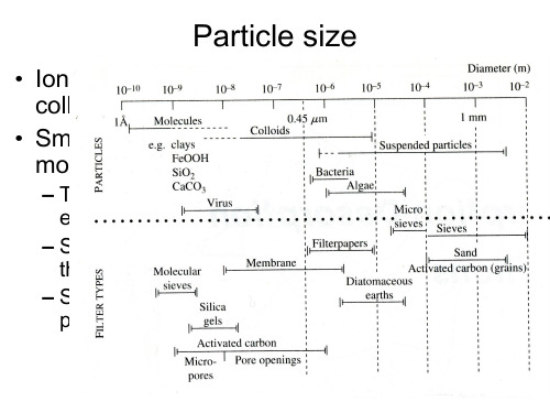

富羧酸基团的共轭微孔聚合物:结构单元对孔隙和气体吸附性能的影响姚婵;李国艳;许彦红【摘要】共轭微孔聚合物(CMPs)骨架中的孔和极性基团对聚合物的气体吸附性能起着重要作用.阐明聚合物中极性基团的效果对该领域的进一步发展是必不可少的.为了解决这个根本问题,我们使用最简单的芳香系统-苯作为建筑单体,构筑了两个新颖的富羧酸基团的CMPs (CMP-COOH@1,CMP-COOH@2),并探讨了CMPs中游离羧酸基团的量对其孔隙、吸附焓、气体吸附和选择性的深远影响.CMP-COOH@1和CMP-COOH@2显示的BET比表面积分别为835和765 m2·g-1.这两种聚合物在二氧化碳存储方面显示了高潜力.在273 K和1.05 x 10⁵ Pa条件下,CMP-COOH@1和CMP-COOH@2的CO2吸附值分别为2.17和2.63 mmol·g-1.我们的研究结果表明,在相同的条件下增加聚合物中羧基基团的含量可以提高材料对气体的吸附容量和选择性.%Polar groups in the skeletons of conjugated microporous polymers (CMPs) play an important role in determining their porosity and gas sorption performance.Understanding the effect of the polar group on the properties of CMPs is essential for further advances in this field.To address this fundamental issue,we used benzene,the simplest aromatic system,as a monomer for the construction of two novel CMPs with multi-carboxylic acid groups in their skeletons (CMP-COOH@1 and CMP-COOH@2).We then explored the profound effect the amount of free carboxylic acid in each polymer had on their porosity,isosteric heat,gas adsorption,and gas selectivity.CMP-COOH@1 and CMP-COOH@2 showed Brunauer-Emmett-Teller (BET) surface areas of835 and 765 m2·g-1,respectively,displaying high potential for carbon dioxide storage applications.CMP-COOH@1 and CMP-COOH@2 exhibited CO2 capture capabilities of 2.17 and 2.63 mmol·g-1 (at 273 K and 1.05 x 10⁵ Pa),respectively,which were higher than those of their counterpart polymers,CMP-1 and CMP-2,which showed CO2 capture capabilities of 1.66 and 2.28 mmol·g-1,respectively.Our results revealed that increasing the number of carboxylic acid groups in polymers could improve their adsorption capacity and selectivity.【期刊名称】《物理化学学报》【年(卷),期】2017(033)009【总页数】7页(P1898-1904)【关键词】共轭微孔聚合物;羧酸;孔;气体吸附;选择性【作者】姚婵;李国艳;许彦红【作者单位】吉林师范大学,环境友好材料制备和应用教育部重点实验室,长春130103;吉林师范大学,环境友好材料制备和应用教育部重点实验室,长春130103;吉林师范大学,环境友好材料制备和应用教育部重点实验室,长春130103;吉林师范大学,功能材料物理与化学教育部重点实验室,吉林四平136000【正文语种】中文【中图分类】O647Carbon dioxide is one of the main greenhouse gases that cause global issues, such as climate warming and increases in sea level and oceanacidity. Modern climate science predicts that the accumulation of greenhouse gases in the atmosphere will contribute to an increase ins urface air temperature of 5.2 °C between the years 1861 and 2100. Carbon capture and sequestration (CCS), a process of CO2 separation and concentration can contribute to solve. For this aim, the use of porous materials tailored for selective CO2 absorption is energetically efficient and technically feasible. Among the numerous and diversified examples of novel porous materials, such as metal-organic frameworks1,2, zeolites3,4, and purely organic materials5,6 are a class of porous organic materials that allow an elaborate design of molecular skeletons and a fine control of nanopores.Conjugated microporous polymers (CMPs) are a unique class of porous organic materials that combine π-conjugated skeletons with permanent nanopores7–10, which is rarely observed in other porous polymers. CMPs have emerged as a powerful platform for synthesizing functional materials that exhibit excellent functional applications, such as heterogeneous catalysts11,12, guest encapsulation13–15, super-capacitive energy storage devices16,17, light-emitting materials18,19, and fluorescent sensors20,21 and so on. Recently, CMPs have emerged as a designable material for the adsorption of gases, such as hydrogen, carbon dioxide, and methane22–24. Although great achievements in synthesizing CMPs have been realized, extremely high Brunauer-Emmet-Teller specific surface areas as high as 6461 m2·g−125, the other pore parameters, such as pore volume, pore size, and pore size distribution, are important in determining the gas sorptionperformance26,27. Moreover, previous work has shown the surface modification of porous polymers with polar group can significantly enhance their CO2 binding energy, resulting in enhancement in CO2 uptake and/or CO2 selectivity28–30. Carboxylic-rich framework interaction is expected due to hydrogen bonding and/or dipole-quadrupole interactions between CO2 and the functional groups of porous polymers31,32. Cooper et al.33,34 reported increasing the heat of adsorption through the introduction of tailored binding functionalities could have more potential to increase the amount of gas adsorbed. Their results demonstrated that carboxylic groups functionalised polymer showed the higher isosteric heat of sorption for CO2. Torrisi et al.35 predicted that the incorporation of carboxylic groups would lead to the higher isosteric heat, challenging the current research emphasis in the literature regarding amine groups for CO2 capture.Herein, we report the synthesis and characterization two high carboxylic groups of porous polymers and investigate their performances in CO2 storage application under high pressure and cryogenic conditions (Scheme 1, CMP-COOH@1 and CMP-COOH@2). The CMPs are highly efficient in the uptake of CO2 by virtue of a synergistic structural effect, and that the carboxylic units improve the uptake, the high porosity provides a large interface, and the swellable skeleton boosts the capacity.1,3,5-Triethynylbenzene (98%) was purchased from TCI, 2,5-dibromobenzoic-3-carboxylic acid (97%) and 2,5-dibromoterephthalicacid(97%) were purchased from Alfa. Tetrakis(4-ethynylphenyl)methane was synthesized according to the literature36. Tetrakis(triphenylphosphine)palladium(0), copper(I) iodide (CuI) andtetra(4-bromophenyl)methane (97%) were purchased from Aladdin. N,N-Dimethylformamide (DMF) (99.9%), triethylamine (99%), methanol (95%) and acetone (95%) were purchased from Aladdin.1H NMR spectra were recorded on Bruker Avance III models HD400 NMR spectrometers, where chemical shifts (δ) were determined with a residual proton of the solventas standard.Fourier transform Infrared (FT-IR) spectra were recorded on a Perkin-Elmer spectrum one model FT-IR-frontier infrared spectrometer.The UV-visible analyzer was used for shimadzu UV-3600. Field-emission scanning electron microscopy (FE-SEM) images were performed on a JEOL model JSM-6700 operating at an accelerating voltage of 5.0 kV. The samples were prepared by drop-casting a tetrahydrofunan (THF) suspension onto mica substrate and then coated with gold.High-resolution transmission electron microscopy (HR-TEM) images were obtained on a JEOL model JEM-3200 microscopy.Powder X-ray diffraction (PXRD) data were recorded on a Rigaku model RINT Ultima III diffractometer by depositing powder on glass substrate, from 2θ = 1.5° up to 2θ = 60° with 0.02° increment. The elemental analysis was carried out on a EuroEA-3000. TGA analysis was carried out using a Q5000IR analyzer with an automated vertical overhead thermobalance. Before measurement, the samples were heated at a rate of 5 °C min−1 under a nitrogen atmosphere. Nitrogen sorption isotherms were measured at 77 K with ASIQ (iQ-2) volumetric adsorption analyzer.Before measurement, thesamples were degassed in vacuum at 150 °C for 12 h. The Brunauer-Emmett-Teller (BET) method was utilized to calculate the specific surface areas and pore volume. BET surface areas were calculated over the relative pressure (p/p0) range of 0.015–0.1. Nitrogen NLDFT pore size distributions were calculated from the nitrogen adsorption branch using a cylindrical pore size model. Carbon dioxide, methane and nitrogen sorption isothermswere measured at 298 or 273 K with a Bel Japan Inc. model BELSORP-max analyzer, respectively. In addition, carbon dioxide sorption isotherms were measured at 318 K and 5 × 10⁶ Pa with a iSorb HP2 analyzer. Before measurement, the samples were also degassed in vacuum at 120 °C for more than 10 h.2.2.1 Synthesis of CMP containing carboxylic groupsAll of the polymer networks containing multi-carboxylic groups were synthesized by palladium(0)-catalyzed cross-coupling polycondensation. All the reactions were carried out at a fixed reaction temperature and reaction time (120 °C/48 h).2.2.2 Synthesis of CMP-COOH@1 and CMP-COOH@22,5-Dibromoterephthalic acid (107 mg, 0.33 mmol) and 1,3,5-triethynylbenzene (50 mg, 0.33 mmol) (CMP-COOH@1)/tetrakis(4-ethynylphenyl)methane (104 mg, 0.25 mmol) (CMP-COOH@2) were put into a 50 mL round-bottom flask, the flask exchanged three cycles under vacuum/N2. Then added to 2 mL N,N-dimethylformamide (DMF) and 2 mL triethylamine (Et3N), the flask was degassed by threefreeze-pump-thaw cycles, purged with N2. When the solution had reached reactiontemperature, a slurry of tetrakis(triphenylphosphine)palladium(0) (23.11 mg, 0.02 mmol) in the 1 mL DMF and copper(I) iodide (4.8 mg, 0.025 mmol) in the 1 mL Et3N (CMP-COOH@1)/(CMP-COOH@2) was added respectively, and the reaction was stirred at 120 °C under nitrogen for 48 h. The solid product was collected by filtration and washed well with hot reaction solvent for 4 times with THF, methanol, acetone, and water, respectively. Further purification of the polymer was carried out by Soxhlet extraction with methanol, and THF for 24 h, respectively, to give CMP-COOH@1(claybank solid, 98 mg, 94% yield), CMP-COOH@2(olivine solid, 142 mg, 90% yield). Elemental Analysis (%) Calcd. (Actual value for an infinite 2D polymer), (CMP-COOH@1) C 67.61, H 2.35. Found: C 64.84, H 2.05. (CMP-COOH@2) C 73.03, H 3.02. Found: C 70.02, H 2.19. Carboxylic-CMP was synthesized by the Sonogashira- Higihara reaction of 1,3,5-triethynylbenzene, tetrakis(4- ethynylphenyl)methane and 2,5-dibromoterephthalic acid in the presence of Pd(0) as catalyst. These two samples were unambiguously characterized by elemental analysis confirmed that the weight percentages of C and H contents are close to the calculated values expected for an infinite 2D polymer. The CMPs were further characterized by infrared spectroscopy (Fig.1). Band soft he primary bromo and borate groups of 2,5-dibromoterephthalic acid at about 598 and 1368 cm−1are absent, respectively. From 2900 to 3200 cm−1aromatic C―H stretching bands appear. A C=C stretching mode at 1600 cm−1is also observed. All networks show the typical C≡C and COOH stretching mode at about 2200and 1700 cm−1, respectivel y, indicating the successfulincorporation of the carboxylic and alkynyl groups into the polymer materials.Field-emission scanning electron microscopy (FE-SEM) displayed that the CMPs adopt a spherical shape with sizes of 100–500 nm (Fig.2). High-resolution transmission electron microscopy (HR-TEM) revealed the homogeneous distribution of nanometer-scale pores in the textures (Fig.S1 (Supporting Information)). Powder X-ray diffraction (PXRD) revealed no diffraction, implying that all the polymers are amorphous (Fig.S2 (Supporting Information)). The TGA results show that the polymers have a good thermal stability, and the thermal degradation temperature is up to ca. 300 °C (Fig.S3 (Supporting Information)). The weight loss below 100 °C is generally attributed to the evaporation of adsorbed water and gas molecules trapped in the micropores.The conjugated polymer networks were dispersed in THF to obtain UV/Vis spectra (Fig.S4 (Supporting Information)). The polymer CMP-COOH@1 shows mainly one wide absorption peak at about 396 nm. Compared to monomer 1,3,5-triethynylbenzene, with narrow absorption maxima at 305 nm, the polymer networks exhibit a large bathochromic shift of around 111 nm. CMP-COOH@2 show similar phenomenon, compared totetrakis(4-ethynylphenyl)methane monomer, with absorption maxima at 325 and 345 nm, the polymer frameworks display a large bathochromic shift of around 68 and 48 nm, respectively. This indicates the effective enlargement of the π-conjugated system through the polycondensation reaction.The porosity of the polymer networks was probed by nitrogen sorption at 77 K. According to the IUPAC classification37, adsorption/desorption isotherms of two polymers showed mainly a type I isotherms. As seen in Fig.3(a), remarkably, the two polymer samples exhibit a steep uptake at a relative pressure of p/p0 < 0.1, suggesting that these samples have micropores. There is a sharp rise in the isotherm for the CMP-COOH@1 at higher relative pressures (p/p0 > 0.8), which indicates the presence of meso/macropores in the samples. These textural meso/macropores can be also found in the corresponding FE-SEM images (Fig.2(a)). However, the shape of the isotherm for the CMP-COOH@2 is significantly different from that of CMP-COOH@1, which displays a significant H2 type hysteresis loop in the desorption branch, characteristic of nanostructured materials with a mesoporous structure (Fig.3(a)). These meso/macropores can be ascribed mostly to interparticulate porosity that exists between the highly aggregated nanoparticles38.The pore size distribution calculated from nonlinear density functional theory (NLDFT) shows that the two polymer networks have relatively broad pore size distribution (Fig.3(b)). CMP-COOH@1 and CMP-COOH@2 showed apparent peaks in the size range 0–2 nm, whereas small fluctuations can be observed at 2–12 nm regions. The pore size distribution curves agree with the shape of the N2 isotherms (Fig.3(a)) and imply the presence of both micropores and mesopores in the two polymers. The contribution of microporosity to the networks can be calculated as the ratio of the micropore volume (Vmicro), over the totalpore volume (Vtotal). The microporosities of CMP-COOH@1 and CMP-*******************%and52.3%,respectively.Thisresultindicates that the two carboxylic networks are predominantly microporous. In addition, the BET surface area of CMP-COOH@1 and CMP-COOH@2 were calculated to be 835 and 765 m2·g−1 in the relative pressure range 0.015–0.1, respectively. The decreased surface area of CMP-COOH@2 compared to CMP-COOH@1 could be due to the CMPs constructed with longer connecting struts have lower BET surface areas39,40.In view of the fact that the CMPs possess two key properties generally associated with high CO2 uptake capacity, e.g., good porosity and abundant COOH sites, the CO2 adsorption of the polymers were investigated up to 1.05 × 10⁵ Pa at both 298 K and 273 K (Fig.4(a, b)), respectively. Remarkably, CMP-COOH@1 and CMP-COOH@2 showed the CO2 adsorption capacities of 1.61 and 1.92 mmol·g−1 at 298 K and 1.05 × 10⁵ Pa, respectively (Fig.4(a)). When the temperature was elevated to 273 K, the polymers CMP-COOH@1 and CMP-COOH@2 displayed the higher CO2 capture of 2.17 and 2.63 mmol·g−1(Fig.4(b)), respectively, which were comparable to that of other microporous hydrocarbon networks41. Despite CMP-COOH@2 with a lower surface area, but which adsorbed more CO2 probably due to it has a higher pore volume. In addition, the isosteric heat of adsorption (Qst) of the polymers was calculated from the CO2 uptake data at 273 K and 298 K by using Clausius-Clapeyron equation (Fig.4(c)). The two polymer networks show the isosteric heats of CO2 adsorption around 35.5 and 30.9 kJ·mol−1. Because there is less carboxylicacid in the structural unit, the CO2Qst of CMP-COOH@2 is lower than that of CMP-COOH@1, which is consistent with that of the previous reported polymers33,34. Moreover, the high pressure CO2 sorption properties of the two polymers were also investigated at 5 × 10⁶ Pa and 318 K. As seen in Fig.4(d), CMP-COOH@1 and CMP-COOH@2 show a nearly linear increase with the increasing pressure no obviously turning point. CMP-COOH@1 and CMP-COOH@2 show the higher CO2 capture capacity of 498 and 434 mg·g−1 at 318 K and 5 × 10⁶ Pa, respectively (Fig.4(d)). These results indicated that the CO2 uptake in these networks at high pressures is not dependent solely on the surface area, pore volume or polar groups in the skeletons, but also the measuring pressure have a large effect on the uptake of gas.In order to investigate the amount of carboxylic group in the network whether affects CO2 adsorption capacity of polymers. We synthesized another two carboxylic conjugated polymer with relatively low amount of carboxylic groups (scheme S1, CMP@1 and CMP@2 (Supporting Information)) based on 2,5-dibromobenzoic acid, 1,3,5-triethynylbenzene and tetrakis(4-ethynylphenyl)methane. They show the BET surface area of 979 and 876 m2·g−1 (Fig.S5 (Supporting Information)), respectively, which is higher to that of counterpart CMP-COOH@1 and CMP-COOH@2. CMP@***********************************–2.0 nm (Fig.S6 (Supporting Information)). The decreased surface area of CMP-COOH@1 compared to CMP@1 could be due to the volume of 2,5-dibromoterephthalic acid in CMP-COOH@1 is obviously larger than 2,5-dibromobenzoic acid in CMP@1, which made the bulky benzen–carboxylic **************************************************** phenomenon can be also observed in CMP-COOH@2 and CMP@2 system. As shown in Fig.4(b), at 273 K and 1.05 × 10⁵ Pa, polymers C MP@1 and****************************************.28mmol·g−1, respectively. The CO2 uptake value of CMP-COOH@1 and CMP-COOH@2 is 1.31 and 1.15-times that of the counterpart CMP@1 and CMP@2, respectively, indicating that increasing amount of carboxylic groups in the CMP networks can improve CO2 uptake. In addition, we calculated the isosteric heats of these polymers, they showed the following order (Fig.4(c)):CMP-COOH@1>CMP-COOH@2>CMP@1>************* there is less carboxylic groups in the structural units of CMP@1 andCMP@2, the CO2Qst of CMP@1 and CMP@2 is lower than that of CMP-COOH@1 and CMP-COOH@2, respectively33,42. In addition, CMP-COOH@1 and CMP-COOH@2 show the higher CO2 capture capacity than that of CMP@1 (447 mg·g−1) and CMP@2 (402 mg·g−1) at 318 K and 5 × 10⁶ Pa, respectively (Fig.4(d)). These results imply the amount of carboxylic groups effects BET surface area, pore volume and isosteric heats lead to different the uptake of gas.As for carbon dioxide capture, high separation properties towards CH4 and N2 are also necessary and important in gas separation applications. In order to investigate the gas adsorption selectivity of the microporous polymer networks, CO2, N2, and CH4 sorption properties were measured by volumetric metho ds at 273 K and 1.05 × 10⁵ Pa. It was found that thetwo porous polymer networks show significantly higher CO2 uptake ability than N2 and CH4 in the whole measurement pressure range (Fig.S7 (Supporting Information)). CO2/CH4 and CO2/N2 selectivity was first evaluated by using the initial slope ratios estimated from Henry′s law constants for single-component adsorption isotherms. The CO2/CH4 selectivityofCMP-COOH@********************************** and 6.2, respectively (Table S1 and Fig.S8 (Supporting Information)). In addition, two polymers exhibited the CO2/N2 adsorption selectivity is 48.2 and 39.5, respectively (Table S1 and Fig.S9 (Supporting Information)). Meanwhile, the gas selective capture was also supported by the results from the ideal adsorbed solution theory (IAST), which has been widely used to predict gas mixture adsorption behavior in the porous materials43,44. Under simulated natural gas conditions (CO2/CH4, 50/50), the experimental CO2 and CH4 isotherms collected at 273 K for carboxylic CMP were fitted to the dual-site Langmuir model and the single-site Langmuir model, respectively (Fig.S10 (Supporting Information)). The calculated IAST data for carboxylic CMP are shown in Table S1. At 273 K and 1.05 × 10⁵ Pa, CMP-COOH@1 and CMP-COOH@2 exhibit an appreciably high selectivity of CO2 over CH4 under natural gas conditions (5.5 and 5.2) (Fig.S10 (Supporting Information)), which is comparable to some reported MOPs, such as A6CMP (5.1) 45, SCMP (4.4–5.2) 30, and P-G1-T (5) 46. Furthermore, the CO2/N2 adsorption selectivities for CMP-COOH@****************************************.8at273K and 1.05 × 10⁵ Pa (Table S1 and Fig.S11 (Supporting Information)),respectively, which is comparable to some reported MOPs, such as ALP-1(35) 38, PCN-TA (33) 47, and PCN-DC (48) 47. These excellent CO2 selective capture performance of carboxylic CMPs evaluated by IAST are consistent with the results calculated from the initial slopes method. In addition, in light of the amount of carboxylic group effect for the uptake of gas, we reasoned that it might be effective for CO2/CH4 and CO2/N2 separations. At 273 K and 1.05 × 10⁵ Pa, CMP@1 and CMP@2 exhibit the selectivities of CO2/CH4 (4.7 and 4.1) and CO2/N2 (32.1 and 30.5) under natural gas conditions via the IAST method (Figs.S10 and S11 (Supporting Information)), respectively, which are lower that of counterpart CMP- COOH@************************************************* carboxylic groups effects selectivity of polymers. These data implys that increasing the amount of carboxylic unit of polymers can improve the adsorption capacity and selectivity of the materials, which suggested the possibility for the surface properties of microporous polymers to be controlled to interact with a specific gas by post-modification.In summary, two carboxylic CMPs with relatively high surface area have been synthesized. The clean energy applications of the polymers have also been investigated and it was found that CMP-COOH@1 and CMP-***********************.63mg·g−1 of carbon dioxide at 1.05 × 10⁵ Pa and 273 K, respectively, which can be competitive with the reported results for porous organic polymers under the same conditions. The free carboxylicacid functionalized polymers show that increasing the amount of carboxylic group of polymers can improve the adsorption capacity andselectivity of the materials under the same conditions, which is a promising candidate for the separation and purification of CO2 from variousCO2/CH4 mixtures such as natural gas and land-fill gas by adsorptive processes.Supporting Information: available free of charge via the internet at.【相关文献】(1) Sumida, K.; Rogow, D. L.; Mason, J. A.; McDonald, T. M.; Bloch, E. D.; Herm, Z. R.; Baeand, T. H.; Long, J. R. Chem. Rev.2012,112, 724. doi: 10.1021/cr2003272(2) Suh, M. P.; Park, H. J.; Prasad, T. K.; Lim, D. W. Chem. Rev. 2012,112, 782. doi:10.1021/cr200274s(3) Coudert, F. X.; Kohen, D. Chem. Mater.2017,29, 2724. doi:10.1021/acs.chemmater.6b03837(4) Jensen, N. K.; Rufford, T. E.; Watson, G.; Zhang, D. K.; Chan, K. I.; May, E. F. J. Chem. Eng. Data2012, 57, 106. doi: 10.1021/je200817w(5) Tan, L.; Tan, B. Chem. Soc. Rev. 2017, doi: 10.1039/C6CS00851H(6) Ghanem, B.S.; Hashem, M.; Harris, K. D. M.; Msayib, K. J.; Xu, M.; Budd, P. M.; Chaukura, N.; Book, D.; Tedds, S.; Walton, A.; McKeown, N. B. Macromolecules2010,43, 5287. doi: 10.1021/ma100640m(7) Xu, Y. H.; Jin, S. B.; Xu, H.; Nagai, A.; Jiang, D. Chem. Soc. Rev.2013,42, 8012.doi:10.1039/C3CS60160A(8) Cooper, A. I. Adv. Mater.2009,21, 1291. doi: 10.1002/adma.200801971(9) Thomas, A.; Kuhn, P.; Weber, J.; Titirici, M. M.; Antonietti, M. Macromol. Rapid. Commun.2009,30, 221. doi: 10.1002/marc.200800642(10) Dawson, R.; Cooper, A. I.; Adams, D. J. Prog. Polym. Sci. 2012, 37, 530.doi:10.1016/j.progpolymsci.2011.09.002(11) Zhang, K.; Kopetzki, D.; Seeberger, P. H.; Antonietti, M.; Vilela, F. Angew. Chem. Int. Ed.2013, 52, 1432. doi: 10.1002/anie.201207163(12) Xie, Z.; Wang, C.; deKrafft, K. E.; Lin, W. J. Am. Chem. Soc.2011,133, 2056.doi:10.1021/ja109166b(13) Li, A.; Sun, H. X.; Tan, D. Z.; Fan, W. J.; Wen, S. H.; Qing, X. J.; Li, G. X.; Li, S. Y.; Deng,W. Q. Energy Environ. Sci.2011,4, 2062. doi: 10.1039/C1EE01092A(14) Wang, X. S.; Liu, J.; Bonefont, J. M.; Yuan, D. Q.; Thallapally, P. K.; Ma, S. Q. Chem. Commun.2013,49, 1533. doi: 10.1039/C2CC38067F(15) Bhunia, A.; Vasylyeva, V.; Janiak, C. Chem. Commun. 2013,49, 3961. doi:10.1039/C3CC41382A(16) Kou, Y.; Xu, Y.; Guo, Z.; Jiang, D. Angew. Chem. Int. Ed.2011,50, 8753. doi:10.1002/anie.201103493(17) Zhuang, X.; Zhang, F.; Wu, D.; Forler, N.; Liang, H.; Wagner, M.; Gehrig, D.; Hansen, M. R.; Laquai, F.; Feng, X. Angew. Chem. Int. Ed.2013,52, 9668. doi:10.1002/anie.201304496(18) Xu, Y.; Nagai, A.; Jiang, D. Chem. Commun.2013, 49, 1591. doi:10.1039/C2CC38211C(19) Xu, Y.; Chen, L.; Guo, Z.; Nagai, A.; Jiang, D. J. Am. Chem. Soc. 2011, 133, 17622. doi: 10.1021/ja208284t(20) Liu, X.; Xu, Y.; Jiang, D. J. Am. Chem. Soc.2012,134, 8738. doi: 10.1021/ja303448r(21) Gu, C.; Huang, N.; Gao, J.; Xu, F.; Xu, Y.; Jiang, D. Angew. Chem. Int. Ed.2014,53, 4850. doi: 10.1002/anie.201402141(22) Liao, Y.; Weber, J.; aul, C. F. J. Chem. Commun.2014, 50, 8002. doi:10.1039/C4CC03026E(23) Lu, W.; Sculley, J. P.; Yuan, D.; Krishna, R.; Wei, Z.; Zhou, H. C. Angew. Chem. Int. Ed. 2012,51, 7480. doi: 10.1002/anie.201202176(24) Xiang, Z.; Cao, D.; Wang, W.; Yang, W.; Han, B.; Lu, J. J. Phys. Chem. C2012,116, 5974. doi: 10.1021/jp300137e(25) Yuan, D.; Lu, W.; Zhan, D.; Zhou, H. Adv. Mater.2011,23, 3723. doi:10.1002/adma.201101759(26) Pu, L.; Sun, Y.; Zhang, Z. J. Phys. Chem. A2010,114, 10842. doi: 10.1021/jp103331a(27) Babarao, R.; Jiang, J. W. Langmuir2008,24, 6270. doi; 10.1021/la800369s(28) Islamoglu, T.; Rabbani, M. G.; El-Kaderi, H. M. J. Mater. Chem. A2013,1, 10259. doi: 10.1039/C3TA12305G(29) Hasmukh, A. P.; Ferdi, K.; Ali, C.; Joonho, P.; Erhan, D.; Yousung, J.; Mert, A.; Cafer, T. Y. J. Mater. Chem.2012,22, 8431. doi: 10.1039/c2jm30761h(30) Qin, L.; Xu, G.; Yao, C.; Xu, Y. Polym. Chem.2016,7, 4599. doi:10.1039/C6PY00666C(31) Rabbani, M. G.; El-Kaderi, H. Chem. Mater.2011,23, 1650. doi:10.1021/cm200411p(32) Arab, P.; Rabbani, M. G.; Sekizkardes, A. K.; İsllamoğlu, T.; El-Kaderi, H. M. Chem. Mater.2014,26, 1385. doi: 10.1021/cm403161e(33) Dawson, R.; Adams, D. J.; Cooper, A. I. Chem. Sci.2011,2, 1173. doi:10.1039/C1SC00100K(34) Dawson, R.; Cooper, A. I.; Adams, D. J. Polym. Int.2013,62, 345.doi:10.1002/pi.4407(35) Torrisi, A.; Mellot-Draznieks, C.; Bell, R. G. J. Chem. Phys.2010,132, 044705. doi: 10.1063/1.3276105(36) Li, P. Z.; Wang, X. J.; Liu, J.; Lim, J. S.; Zou, R.; Zhao, Y. J. Am. Chem. Soc.2016, 138, 2142. doi: 10.1021/jacs.5b13335(37) Rose, M.; Klein, N.; Bohlmann, W.; Bohringer, B.; Fichtner, S.; Kaskel, S. Soft Matter2010,6, 3918. doi: 10.1039/C003130E(38) Chen, Q.; Luo, M.; Hammershoj, P.; Zhou, D.; Han, Y.; Laursen, B. W.; Yan, C. G.; Han, B. H. J. Am. Soc. Chem. 2012,134, 6084. doi: 10.1021/ja300438w(39) Jiang, J. X.; Su, F. B.; Trewin, A.; Wood, C. D.; Niu, H. J.; Jones, J. T. A.; Khimyak, Y. Z.; Cooper, A. I. J. Am. Chem. Soc.2008,130, 7710.doi: 10.1021/ja8010176(40) Jiang, J. X.; Trewin, A.; Adams, D. J.; Cooper, A. I. Chem. Sci.2011,2, 1777. doi:10.1039/C1SC00329A(41) Meng, B.; Li, H.; Mahurin, S. M.; Liu, H.; Dai, S. Rsc. Adv.2016,6, 110307. doi:10.1039/C6RA18307G(42) Ma, H.; Ren, H.; Zou, X.; Meng, S.; Sun, F.; Zhu, G. Polym. Chem.2014,5, 144. doi; 10.1039/C3PY00647F(43) Obrien, J. A.; Myers, A. L. Ind. Eng. Chem. Res.1988, 27, 2085. doi:10.1039/C3PY00647F(44) Wang, K.; Qiao, S. Z.; Hu, X. J. Sep. Purif. Technol.2000,20, 243. doi:10.1016/S1383-5866(00)00087-3(45) Qin, L.; Xu, G.; Yao, C.; Xu, Y. Chem. Commun.2016,52, 12602. doi:10.1039/C6CC05097B(46) Qiao, S.; Wang, T.; Huang, W.; Jiang, J. X.; Du, Z.; Shieh, F.; Yang, R. Polym. Chem.2016,7, 1281. doi: 10.1039/C5PY01767J(47) Shen, C.; Yan, J.; Deng, G.; Zhang, B.; Wang, Z. Polym. Chem.2017,8, 1074. doi: 10.1039/C6PY02050J。


不同热风干燥温度对枸杞干燥特性的影响胡云峰;位锦锦;李宁宁;胡晗艳【摘要】为了研究枸杞在不同热风干燥温度下的干燥特性,改善其干制品质,以宁夏枸杞为原料,对其进行不同温度的热风干燥处理,分析它的干燥特性和品质变化,结果表明:枸杞干制过程由升速、降速和恒速3个阶段组成,以降速阶段为主要过程;构杞热风干燥水分有效扩散系数在0.76×10⁻¹⁰m2/s和1.98 ×1010 m2/s之间,且温度越高系数越大,枸杞干燥活化能为61.36 kJ/mol;通过试验得出风速为0.2 m/s、湿度为30%、物料厚度1层(8 mm)恒定不变,温度为55℃热风干燥时制得的枸杞品质最好;此外,由枸杞的感官品质分析结果得出:色泽、口感和质地对枸杞的品质有重要的影响.【期刊名称】《食品与发酵工业》【年(卷),期】2017(043)001【总页数】5页(P130-134)【关键词】枸杞;热风干燥;干制特性;品质【作者】胡云峰;位锦锦;李宁宁;胡晗艳【作者单位】天津科技大学食品工程与生物技术学院,天津,300457;天津科技大学食品工程与生物技术学院,天津,300457;天津科技大学食品工程与生物技术学院,天津,300457;天津市食品加工工程中心,天津,300457【正文语种】中文枸杞(Lycium barbarum)是我国传统常用药食同源材料[1]。
我国枸杞资源丰富,主要分布在宁夏、新疆、内蒙古、河北等省区,全国年总产量接近1亿万t[2]。
鲜枸杞营养丰富,含水量高,但易腐烂变质,难以贮藏,目前除少量鲜食外,大部分枸杞被作为干果销售[3]。
在我国,枸杞的干制普遍采用晒干、烘干等传统技术,其生产成本低,周期长且品质差。
因而,一些干燥技术,如热风干燥、真空冷冻干燥、微波干燥、远红外干燥等开始被广泛研究并应用,其中,热风干燥是目前应用较普遍的干燥技术[4]。
贾清华等[5]对枸杞热风干制特性进行研究,发现温度是影响干燥速率的主要因素。

收稿日期:2006-08-24基金项目:国家“八六三”高技术研究发展计划资助项目(2002AA601130)作者简介:黄 鑫(1980—),男,博士生,主要研究方向为给水处理理论与技术,E 2mail :huangxin -china @ ;高乃云(1950—),女,教授,博士生导师,工学博士,主要研究方向为水处理理论与技术,E 2mail :gaonaiyun @ 改性活性炭对镉的吸附研究黄 鑫,高乃云,张巧丽(同济大学污染控制与资源化研究国家重点试验室,上海 200092)摘要:研究镉在表面氧化改性的颗粒活性炭上的吸附行为.考察离子强度、p H 值、温度和镉初始浓度对吸附的影响,并进行相应的动力学与热力学计算.结果表明,实验范围内,活性炭对镉的吸附在p H =2~7范围内与p H 值呈正相关,增加离子强度对吸附有一定的阻碍作用;吸附动态曲线符合二级动力学模型;活性炭与镉之间的标准吸附热约为-25.29kJ ・mol -1,整个温度范围内吸附是自发的放热过程.关键词:改性活性炭;热力学;镉;动力学;吸附;内分泌干扰物中图分类号:TU 991 文献标识码:A 文章编号:0253-374X (2008)04-0508-06Research on Cadmium Adsorption by ModifiedG ranular Activated CarbonHUA N G Xi n ,GA O N aiyun ,ZHA N G Qiaoli(State K ey Laboratory of Pollution Control and Resource Reuse ,Tongji University ,Shanghai 200092,China )Abstract :Cadmium adsorption behaviour of modified granular activated carbon was investigated.Ex 2periments were conducted to study the effect of parameters ,such as ionic strength ,p H ,equilibrium time and initial cadmium concentration.The adsorption capacity of modified granular activated carbon enlarged with an increase in p H ,and reduced with an increase in ionic strength.The adsorption pro 2cess followed pseudo 2second order rate model.Thermodynamic calculation was employed based on ad 2sorption isotherms at different temperatures.The average change of standard adsorption heat ΔH was -25.29kJ ・mol -1.Negative ΔH and ΔG values indicate the adsorption process for cadmium onto the studied activated carbon is exothermic and spontaneous.Key words :modified activated carbon ;thermodynamics ;cadmium ;kinetics ;adsorption ;endocrinedisrupting chemicals 2005年,广东省北江和湖南省湘江相继出现了有关饮用水源遭受镉污染的报道.镉(Cd (Ⅱ))是典型的环境重金属污染物,容易迁移进入人的食物链而危害人类的健康[1].世界自然基金会的《环境中具有生殖和内分泌干扰作用的化学物质清单》将其和铅、汞一起列为仅有的3种金属类内分泌干扰物.美国环保局和日本环境厅也分别将镉列为疑似内分泌干扰物[2].饮用水水源中镉的长期低浓度效应不可忽视.吸附工艺处理效果稳定,价格相对较低,尤其适第36卷第4期2008年4月同济大学学报(自然科学版)JOURNAL OF TON G J I UN IVERSITY (NATURAL SCIENCE )Vol.36No.4 Apr.2008用于大流量低浓度污染物质的去除.目前已有大量文献报道了不同吸附剂对镉的去除[325],但大多采用生物材料与废弃物,其化学稳定性尚待检验,应用中也多以废水处理中金属离子的回收为研究目的.本文将某商品颗粒活性炭表面氧化改性,显著提高了它对水中镉的吸附性能.通过对相关影响因素的考察及吸附热力学和动力学的研究,对该改性颗粒活性炭与镉的作用机理作初步探讨.1 实验部分1.1 活性炭材料的准备实验选用某破碎颗粒活性炭(碘值为1046mg ・g-1,亚甲蓝值为198mg・g-1,强度为93.5%),实验表明该炭对镉基本无吸附作用.颗粒活性炭使用前预处理以去除表面杂质,并通过化学氧化进行表面改性,具体方法参见文献[6]:筛分活性炭60~80目,在三氯甲烷中浸泡4h,120℃下烘箱(101AS-2,上海浦东荣丰科学仪器公司)中烘干.用经水稀释的浓硝酸(体积比1∶1)浸泡并在沸腾温度下加热回流1h,置水漂洗至中性,120℃下干燥8h.马弗炉中300℃加热1h,冷却,密闭封存待用.实验中所用试剂均为化学纯.1.2 实验方法称量0.15g活性炭置于250ml碘量瓶中,向瓶中加入100ml Cd2+浓度为4.5μmol・L-1的去离子水溶液,再加入10ml浓度为1mol・L-1的KNO3作为离子支持(此时离子强度I=0.01mol・L-1).原液p H值约为6.0.分别选取20,25,35,42℃(±0.5℃)4个温度,在恒温摇床(H YG2A,江苏太仓实验设备厂)以160r・min-1的摇速持续振荡3~4d,直至吸附平衡后取出部分溶液,过滤,测定镉浓度,并计算相应吸附量.不加活性炭的空白试验表明碘量瓶对镉的吸附作用可以忽略不计.镉的浓度用等离子发射光谱法进行测定(Optima2100DV,PE公司),测定波长λ为228.8nm,线性范围为5μg・L-1~50mg・L-1.1.3 数据计算吸附动力学曲线分别用一级动力学方程、二级动力学方程和粒子内扩散模型(intraparticle diffu2 sion model)进行拟合[7-8].log(q t-q e)=log q e-k1t/2.303t/q t=1/v0+t/q e,v0=k2q2eq t=k d t1/2式中:q t,q e分别为t时刻与平衡时吸附容量,μmol ・g-1;k1为系数,min-1;t为时间,min;v0为初始吸附速率,μmol・g-1・min-1;k2为系数,g・μmol-1・min-1,k d为系数,μmol・g-1・min-1/2.吸附等温线采用Langmuir和Freundlich等温式,分别为c e/q e=1/(q m b)+c e/q mlg q e=(1/n)lg c e+lg K f式中:c e为平衡时剩余浓度;q m为单分子层饱和吸附量,μmol・L-1;b为系数,L・μmol-1;n为系数;K f 为系数,μmol・g-1.根据Van’t Hoff方程进行吸附热力学计算[7]ΔG=-R T ln Kdln K d=ΔH/(-R T)+ΔS/R式中:ΔG为吸附的标准自由能改变量,kJ・mol-1; R为气体摩尔常数;T为绝对温度,K;K d为吸附热力学平衡常数;ΔH为标准吸附热,kJ・mol-1;ΔS为吸附的标准熵变值,J・mol-1・K-1.2 结果与讨论2.1 pH值对活性炭吸附镉的影响图1中2条虚线分别表示理想溶液中Cd2+和Cd(OH)+这2种物质与总镉的数量比例随p H值的变化[3].随p H值增大,Cd(OH)+比例逐渐增多,溶质的平均电荷密度减小.提高p H值也使得活性炭表面的负电性增大.活性炭与镉之间静电引力的变化主要看这2种变化哪一种占主导.图1中去除率在p H=2~7范围内随p H值增大而增大;在p H=4~6范围内的变化很快,曲线陡峭,p H=4及p H=6对应的去除率分别约为19.8%和80%.表面氧化的作用主要是增加活性炭表面含氧官能团的数量.有研究认为活性炭表面羧基的水解常数p Ka=3~6,增大p H值可促进羧基的水解,提高表面电负性,增大镉与活性炭之间的静电引力,强化活性炭的表面官能团与镉的络合作用.2.2 离子强度对吸附的影响考察离子强度对活性炭吸附镉的影响.KNO3离子强度I分别为0.001,0.010,0.100mol・L-1时(图2),随KNO3浓度的增加,活性炭的吸附作用逐渐减弱.镉初始浓度为4.5μmol・L-1,Freundlich公式拟合25℃3种离子强度下的吸附曲线为905 第4期黄 鑫,等:改性活性炭对镉的吸附研究 log q t =1.1569+1.413log c e ,R 2=0.9964log q t =1.1587+1.652log c e ,R 2=0.9971log q t =1.5751+5.857log c e ,R 2=0.7718图1 pH 对活性炭吸附镉的影响Fig.1 Sorption eff iciency of cadmium on modif iedgranular activ ated carbon at different pH v alu es其中,R 2为回归常数.在I =0.001,0.010mol ・L -12种溶液中,活性炭吸附性能相差不大,且都可以用Freundlich 公式拟合,线性良好.I =0.100mol ・L -1时吸附性能急剧下降.离子强度对于活性炭吸附镉有一定的阻碍作用.Y oussef A M 等人在活性炭吸附镉的试验中添加氯化钠,也得到类似结果[9].图2 离子强度对活性炭吸附镉的影响Fig.2 E ffect of ionic strength on removal of cadmium2.3 时间对吸附的影响在活性炭质量浓度为1.5g ・L -1,c 0=55~60μmol ・L -1,p H =6.0的条件下,4个温度的吸附在1500min (约1d )左右基本可以达到平衡(如图3).前10h 的吸附量占平衡吸附量的比率约为30%.吸附过程较为缓慢.推测在吸附初期,孔内扩散作用控制反应速率.图3 不同温度下活性炭对镉的吸附动力学曲线Fig.3 E ffect of sorption time on removal of cadmiumat different temperatures 图4显示粒子内扩散模型对吸附动态曲线的拟合情况.由图可见,在0~225min 范围内,温度为293K 和298K 的对应曲线呈线性;而308K 和315K 2个温度下对应曲线的线性范围更宽,约为0~600min.随着吸附达到一定时间,粒子内扩散模型不再适用于镉的吸附过程.这可能由于随吸附量的增加,空间位阻作用与炭表面的静电斥力作用增强,使得孔内扩散阻力增加所致.图4 镉在活性炭上吸附的粒子内扩散模型拟合Fig.4 Intraparticle diffusion plots for cadmiumadsorption on modif ied G AC 3种模型的拟合情况见表1.k d 是基于最初的线性范围计算出的值.从相关系数上看,一级反应方程的拟合效果不如二级反应方程.有文献指出,由于一级反应需要估算平衡吸附容量q e 值,对于吸附较慢的过程不能准确计算,常常只适用于吸附的初期[8].二级反应方程可较好地对反应进行拟合,相关系数在0.97以上,计算出的平衡吸附容量与试验所得相吻合.说明活性炭吸附镉的过程主要受化学作用所控制,而不受物质传输步骤控制[7-8].15 同济大学学报(自然科学版)第36卷 表1 动力学模型拟合参数T ab.1 First2order,second2order and intraparticle diffusion rate constantsT/K一级反应方程拟合k1/(10-3min-1)R2二级反应方程拟合q e/(μmol・g-1)v0/(μmol・g-1・min-1)R2内扩散模型拟合k d/(μmol・g-1・min-1/2)R2293 2.460.90618.830.04400.999 1.4210.989 298 1.530.98516.670.02890.999 1.1860.983 308 1.160.91512.790.02120.9740.2370.995 315 1.460.98422.680.04790.9940.4810.999 注:内扩散模型只对线性部分进行拟合. 图3以及表1的计算都显示,温度从273K升高至315K时,平衡吸附容量先降低再升高.在308 K时达到最低值12.79μmol・g-1,315K时达到最高值22.68μmol・g-1.二级动力学方程的v0,一级动力学方程的k1和粒子内扩散模型中的k d都有相似的趋势,即随温度的升高先降低再升高.这反映活性炭吸附镉的多种机理并存.推测在以物理吸附为主导的阶段,提高温度使平衡吸附容量降低.当温度达到308K左右时,静电力与离子交换作用等物理吸附作用减弱,温度进一步提高后化学反应增强并占主导,使得吸附速度与容量都增大.2.4 吸附等温线如图5所示,同一温度下活性炭的吸附容量随初始浓度的提高而提高,到一定程度后达到饱和吸附量.当浓度较低时,4条曲线相隔较近.当浓度大于50μmol・L-1时,在293~315K的温度范围内,活性炭对镉的吸附容量先下降后上升,在308K左右达到谷底,然后上升.该趋势与吸附动力学曲线类似(见图3).将曲线用经典的Langmuir和Freundlich 模型进行拟合,结果见表2.图5 活性炭对镉的吸附等温线Fig.5 C admium adsorption isotherms of modif iedgranular activated carbon表2 Freundlich与Langmuir方程的拟合参数T ab.2 Freundlich equ ation and Langmuir equ ation constantT/KFreundlich方程拟合1/n K f/(μmol・g-1)R2Langmuir方程拟合q m/(μmol・g-1)b/(L・μmol-1)R22930.568 2.3960.93851.020.031860.967 2980.622 1.6470.97542.920.035530.962 3080.506 1.6890.94724.510.054150.998 3150.604 1.4320.94931.060.055460.996 计算结果表明,实验温度范围内1/n的值介于0.1~1.0之间,说明该条件下吸附比较容易进行[10].Langmuir方程拟合效果好于Freundlich方程,计算出的平衡吸附容量与实际情况相近.但从表2可见b值的变化是随温度升高而升高,没有体现出随温度升高先降后升的复杂变化.同样K f与n 也不能很好地反映整个吸附过程.由于Langmuir与Freundlich方程是由理想的气态吸附推导而得到,与实际水溶液中的吸附不尽相同.水合镉离子在水溶液中存在不同形式,不同形式的镉与活性炭表面官能团有不同的作用机理.可能由于离子交换、静电引力与表面反应等作用力共存,各种力在温度变化时此消彼长,显现出复杂的表征,同时活性炭表面吸附位不均一,因而很难用简单的宏观吸附模型来描述整个吸附情况.2.5 吸附热力学吸附热力学的研究有助理解吸附本质.用Van’t Hoff方程的关键是平衡吸附常数K d的确定,文献115 第4期黄 鑫,等:改性活性炭对镉的吸附研究 中有多种计算方法.本文根据文献[7,9210],分别用Langmuir与Freundlich方程拟合参数计算K d,同时依据吸附等温线令K d=q e/c e,3种计算方法的结果列于表3.对应的Van’t Hoff方程拟合情况见图6,对应的ln K d-1/T图的线性相关系数分别为R2 =0.935,K d=K n f;R2=0.806,K d=1/n;R2= 0.968,K d=q e/c e.如前所述吸附趋势随温度上升呈现先降后升的现象.但由于数据较少,故未将308 K,315K对应的等温线单独计算,而是统一计算整个293~315K范围内的吸附过程.虽然线性关系不是很好,但可在一定程度上提供信息作参考.比较表3数据,3种方法计算结果较为一致之处是:标准吸附热ΔH比较接近,为(-25.29±3.34)kJ・mol-1;标准吸附熵变ΔS都为负值.ΔH为负值,说明整个温度范围内吸附过程放热.吸附质从溶液中聚集到固体表面是无序到有序的熵减过程,但同时也会将固体表面的水分子释放到溶液中去,该过程是熵增的.系统熵的变化是这2种情况的加和.活性炭表面基团与镉间有多种力存在,离子交换作用只占小部分.这可能是吸附的熵减作用占主导的主要原因. Von Open B等人测定了各种作用力引起的吸附热的范围为:范德华力4~10kJ・mol-1,疏水键力约为5kJ・mol-1,氢键力2~40kJ・mol-1,配位基交换约为40kJ・mol-1,偶极间作用力2~29kJ・mol-1,化学键力大于60kJ・mol-1[11].实验中吸附热的计算值为25.29kJ・mol-1,可以判断改性活性炭与溶液中镉的作用是氢键力和偶极作用力占主导.图4中吸附易受离子强度影响说明作用力为非强键力(配位基交换与化合键力),也侧面支持了上述观点.此外,根据Freundlich和Langmuir方程参数计算得到的ΔG在所有温度范围内均为负值,说明活性炭吸附镉是自发的过程,与实际情况一致.按照K d=q e/ c e计算得到的ΔG与前二者相差较大,并且Van’t Hoff方程线性拟合系数只有0.806左右.说明用该方法并不能很好地反映本实验中的吸附过程.表3 活性炭吸附镉的热力学函数T ab.3 Thermodynamic parameters of the cadmium adsorption on modif iedgranular activated carbon at different tem peraturesK d计算方法T/K K dΔG/(kJ・mol-1)ΔS/(J・mol-1・K-1)ΔH/(kJ・mol-1)K d=K n[10]f 293 4.66-3.54298 3.01-3.14308 2.82-2.33315 1.81-1.77-80.71-27.19K d=1/b[9]29331.39-8.3929828.15-8.1730818.47-7.7331518.03-7.41-44.52-21.44K d=q e/c e[7]2930.142 4.862980.119 5.413080.059 6.513150.0757.21-109.6-27.25图6 V an’t H off方程拟合活性炭对镉的吸附Fig.6 V an’t H off plot for the cadmium adsorptionon activated carbon3 结论(1)表面氧化改性活性炭除镉效果良好.增大p H值可显著提高去除率,离子强度对吸附过程有一定的阻碍作用.(2)二级动力学方程可很好地描述吸附动态曲线.孔内扩散模型与一级动力学方程均只适用于吸附初期.(3)热力学计算表明标准吸附热约为-25.29kJ・mol-1,整个温度范围内吸附是自发的放热过程.活性炭吸附镉存在多种机理,既有离子交换、表面络215 同济大学学报(自然科学版)第36卷 合等物理吸附,又有化学反应.随温度变化各种力的大小也发生变化.参考文献:[1] 夏汉平.土壤2植物系统中的镉研究进展[J].应用与环境生物学报,1997,3(3):289. XIA Hanping.Studies on cadmium in soil2plant stem[J].Chinese Journal of App1ied Environmental Biology,1997,3(3):289.[2] 任仁,黄俊.哪些物质属于内分泌干扰物(EDCs)[J].安全与环境工程,2004,11(3):7. REN Ren,HUAN G J un.An introduction to endocrine disrupters(EDCs)[J].Safety and Environment Engineering,2004,11(3):7.[3] Shin Eun Woo,Rowell Roger M.Cadmium ion sorption ontolignocellulosic biosorbent modified by sulfonation:the origin ofsorption capacity improvement[J].Chemosphere,2005,60(8):1054.[4] Choy K eith K H,Mc K ay G ordon.Sorption of cadmium,cop2per,and zinc ions onto bone char using Crank diffusion model[J].Chemosphere,2005,60(8):1141.[5] Abou2Mesalam M M.Sorption kinetics of copper,zinc,cadmium and nickel ions on synthesized silico2antimonate ionexchanger[J].Colloids and Surfaces A:Physicochemical andEngineering Aspects,2003,225(3):85.[6] 白树林,赵桂英,付希贤.改性活性炭对水溶液中Cr(Ⅲ)吸附的研究[J].化学研究与应用,2001,13(6):270. BAI Shulin,ZHAO Guiying,FU Xixian.Improvement of adsorption of Cr(Ⅲ)from aqueous solution by activated carbon[J].Chemical Research and Application,2001,13(6):270. [7] Ho Y S,Mc K ay G.Pseudo2second order model for sorptionprocesses[J].Process Biochemistry,1999,34:451.[8] 丁世敏,封享华,汪玉庭,等.交联壳聚糖多孔微球对染料的吸附平衡及吸附动力学分析[J].分析科学学报,2005,21(2):127. DIN G Shimin,FEN G Xianghua,WAN G Yuting,et al.Equi2 librium and kinetic analysis of adsorption for dyestuff bycrosslinked chitosan porous microbeads[J].Journal of AnalyticalScience,2005,21(2):127.[9] 沈学优,卢瑛莹,朱利中.对硝基苯酚在水/有机膨润土界面的吸附行为[J].中国环境科学,2003,23(4):367. SHEN Xueyou,LU Y ingying,ZHU Lizhong.Sorption behavior of p2nitrophenol on the boundary of water and organobentonite—the thermodynamic character and mechanism[J].Journal ofChina Environmental Science,2003,23(4),367.[10] 张增强,张一平.几个吸附等温模型热力学参数的计算方法[J].西北农业大学学报,1998,26(2):94. ZHAN G Zengqiang,ZHAN G Y iping.Method of calculating the thermodynamic parameters from some isothermal absorptionmodels[J].Acta of Northwest Sci2Tech University of Agricul2ture and Forestry,1998,26(2):94.[11] Von Open B,K ordel W,K lein W.Sorption of nonpolar andpolar compounds to soils:Processes,measurement and experi2ence with the applicability of the modified OECD2guideline[J].Chemosphere,1991,22:285.・下期文章摘要预报・SiC/AI双面焊的残余应力分析程 军,陈 英 运用有限元软件ANSYS对SiC/A I的双面焊过程进行了数值分析.采用高斯圆柱热源模型模拟激光焊源,利用APDL编写循环程序现热源的移动,得到SiC/A I双面焊过程的温度场分布和冷却后的残余力场.从平行焊接方向陶瓷侧靠近焊缝处的横向和纵向残余应力分布曲线可见:第一道焊表面(正面)的纵向残余应力在其边缘端均为压应力,并迅速向内转变为拉应力;而第二道焊表面(反面)的纵向残余应力却正好相反,其边缘端均为拉应力,并迅速向内转变为压应力.而横向残余应力均为压应力,最大值分布在两侧.在焊缝两侧,横向与纵向残余应力均发生跳跃变化.315 第4期黄 鑫,等:改性活性炭对镉的吸附研究 。


Engineers C,June2002UK.INTRODUCTIONControlling the moisture content during the processing of foods is an ancient method of preservation.This is achieved by either removing water,or binding it such that the food becomes stable to both microbial and chemical deteriora-tion1.For this reason much attention has been given to the sorption properties of foods.Sorption characteristics have, and are currently being examined in light of their in uence on the storage stability of dehydrated products,as well as their effect on the diffusion of water vapour2.Walter3in1924was probably the rst researcher to relate relative water vapour pressure to microbial growth,the main cause of food spoil-age.A decade afterwards,Scott4and Salwin5independently applied this relationship and introduced the concept of water activity(a w).This is a term indicating the‘quality’of the water content of food.It describes the degree of‘boundness’of water and hence,its availability to participate in physical, chemical,and microbiological reactions.Since then,experi-mental and theoretical studies of the water associated with foods have been intensi ed in an attempt to understand and interpret water behaviour.Such endeavours have been fraught with dif culties because foods are heterogeneous mixtures of soluble organic and inorganic materials6.The properties of water,in relation to biological system, can be classi ed into three categories6.(1)Structural Aspects:the position and orientation ofwater molecules in relation to each other and to macromolecules;(2)Dynamic Aspects:molecular motions of water and theircontribution to the hydrodynamic properties of the system;(3)Thermodynamic Aspects:water in equilibrium with itssurroundings,at a certain relative humidity and temperature.W ATER ACTIVITYWater,the most abundant constituent of natural foods,has many roles in food processing and,while the chemistry is simple,the impact on food reactions and food quality is greater than any other chemical component7.Karel8consid-ered water to be the most important plasticizer‘mobility enhancer’for hydrophilic food component,i.e.its low molecular weight leads to a large increase in mobility,due to increased free volume(the volume of the polymer-plasticizer mixture that is not occupied by molecules)and decreased local viscosity9.In biological systems,such as foods,water is believed to exist with either unhindered or hindered mobility,referred to as free and bound water,respectively.The amount of water held by the food product,under a speci c set of conditions,is traditionallyreferred to as the water-holding or water-binding capacity of the material.The often ill-de ned term,‘bound water’is usually considered as that portion of water held in the material which exhibits physical properties signi cantly different from those of free,or bulk,water10.It has been suggested that the water is bound to stronger hydrogen bond acceptors than liquid water(possibly with favoured hydrogen bond angles)as well as water-solvating nonpolar groups.According to Luck11,bound water has a reduced solubility for other compounds,causes a reduction in the diffusion of water-soluble solutes in the sorbent,and exhibits a decrease in diffusion coef cient with decreasing moisture content.The decreased diffusion velocity impedes drying processes because of slower diffusion of water to the surface.Some of the characteristics of bound water are lower vapour pressure,high binding energy as measured during dehydration,reduced mobility as seen by nuclear magnetic resonance(NMR),unfreezability at low temperature,and unavailability as a solvent12.Although each of these char-acteristics has been used to de ne bound water,each gives a118different value for the amount of water which is bound.As a result of this,as well as the complexities and interactions of the binding forces involved,no universal de nition of bound water has been adopted.The concept of water activity,that is used most commonly by researchers in the food industry,can be de ned as:a w ˆp =p 0ˆrelative humidiy…1†where p is the partial pressure of water in the food (atm),and p 0the vapour pressure of pure water at the same temperature (atm).MOISTURE SORPTION ISOTHERMThe relationship between total moisture content and the water activity of the food,over a range of values,and at a constant temperature,yields a moisture sorption isotherm when expressed graphically .This isotherm curve can be obtained in one of two ways (see Figure 1):(i)an adsorption isotherm is obtained by placing a com-pletely dry material into various atmospheres of increas-ing relative humidity and measuring the weight gain due to water uptake;(ii)a desorption isotherm is found by placing an initiallywet material under the same relative humidities,and measuring the loss in weight 2.The adsorption and desorption processes are not fully reversible,therefore a distinction can be made between the adsorption and desorption isotherms by determining whether the moisture levels within the product are increas-ing indicating wetting,or whether the moisture is gradually lowering to reach equilibrium with its surroundings,imply-ing that the product is being dried.On the basis of the van der Waals adsorption of gases on various solid substrates,Brunauer et al.13classi ed adsorp-tion isotherms into ve general types (see Figure 2).Type I is the Langmuir,and T ype II the sigmoid shaped adsorption isotherm;however,no special names have been attached to the other three types.Types II and III are closely related to Types IV and V ,except that the maximum adsorption occurs at a pressure lower than the vapour pressure of the gas.If,however,the solid is porous so that it has an internal surface,then the thickness of the adsorbed layer on the walls of the pores is necessarily limited by the width of the pores.The form of the isotherm is modi ed correspondingly;instead of Type II and III,Type IV and V exist 14.Moisture sorption isotherms of most foods are nonlinear,generally sigmoidal in shape,and have been classi ed as Type II isotherms.Caurie 15suggested that most of the water in fresh food exerts a vapour pressure very close to that of pure water,i.e.unity.This vapour pressure level is main-tained until the moisture content of the food decreases to about 22%.The moisture level is then no longer able to sustain the vapour pressure of the food at unity,and there-fore,begins to show a lowered vapour pressure,as if in solution.The changes with atmospheric humidity of this last fraction (22%)of water in dehydrated foods result in the characteristic sigmoid shape of water sorption isotherms.Rowland 16suggested that the direct plasticizing effect of increasing moisture content at constant temperature is equivalent to the effect of increasing temperature at constant moisture and leads to increased segmental mobility of chains in amorphous regions of glassy and partially crystal-line polymers.Foods rich in soluble components,such as sugars,however,have been found to show Type III behaviour,this is due to the solubility of sugars in water 17.Chinachoti and Steinberg 18found that sucrose added to starch gels sharply increased the sorption of water at water activities higher than 0.85.The sorption isotherm characteristics of many food pro-ducts have been determined experimentally (see Table 1),and have been further characterized according to the Brunauer et al.13classi cation;a number of examples are presented in Table 2.For interpretation purposes,the generalized moisture sorption isotherm for a hypothetical food system may be divided into three main regions,as detailed in Figure 1.Region A represents strongly bound water with an enthalpy of vaporization considerably higher than that of pure water.A typical case is sorption of water onto highly hydrophilic biopolymers such proteins and polysaccharides.The moist-ure content theoretically ,represents the adsorption of the rst layer of water ually,water molecules in this region are unfreezable and are not available for chemical reactions or as plasticizers.Most dried food products are empirically observed to display their greatest stability at moisture contents comparable to the monolayer moisture content 19.Figure 1.Generalized sorption isotherm for food products 91.Figure 2.Five types of van der Waals adsorption isotherm 13.MOISTURE SORPTION ISOTHERM CHARACTERISTICS 119Trans IChemE,Vol 80,Part C,June 2002Region B,represents water molecules which are less rmly bound,initially as multilayers above the monolayer .In this region,water is held in the solid matrix by capillary conden-sation.This water is available as a solvent for low-molecular-weight solutes and for some biochemical reactions.The quantity of water present in the material that does not freeze at the normal freezing point usually is within this region.In region C or above,excess water is present in macro-capillaries or as part of the uid phase in high moisture materials This exhibits nearly all the properties of bulk water,and thus is capable of acting as a solvent.Microbial growth becomes a major deteriorative reaction in this region 20,21.The variation in sorption properties of foods reported in the literature is caused by biological variation in foods,pre-treatment of food,and differences in experimental techni-ques adopted (gravimetric,manometric or hygrometric)22.EFFECT OF TEMPERA TURE ON SORPTIONISOTHERMS The effect of temperature on the sorption isotherm is of great importance given that foods are exposed to a range of temperatures during storage and processing and water activity changes with temperature.Temperature affects the mobilityof water molecules and the dynamic equilibrium between the vapour and adsorbed phases.In general,researchers have found that if the water activity is maintained constant,an increase in temperature causes a decrease in the amount of sorbed water.Iglesias and Chirife 23considered this to indicate that the food is becoming less hygroscopic.Palipane and Driscoll 24suggested that at higher temperatures some water molecules are activated to energy levels that allow them to break away from their sorption sites,thus decreasing the equilibrium moisture content.A deviation from this beha-viour,however,has been shown by certain sugars (glucose)and other low molecular weight food constituents (salt),which become more hygroscopic at higher temperatures due to their ability to dissolve in water 25.Saravacos et al.22observed the intersection of the 20¯C and 30¯C isotherm curves of sultana raisins at a water activity of approximately 0.78.This was also reported by Saravacos and Stinch eld 26for model systems containing starch and glucose.Similar effects of temperature on the isotherm characteristics have been observed by Audu et al.27for sugars,and Weisser et al.28for sugar alcohol.Tsami et al.29found similar results for dried fruits,up to a water activity of 0.55–0.7.However,forwaterTable 1.Summary of moisture sorption isotherm characteristics of food materials.Table 2.T ypes of van der Waals adsorption isotherms observed for different food materials.Trans IChemE,Vol 80,Part C,June 2002120AL-MUHTASEB et al.activity values greater than0.7,there was an inversion of the effect of temperature(equilibrium moisture content increased with temperature).This phenomenonwas attributedto thefact that,in general,at low a w values the sorption of water is due mainly to the biopolymers,with an increase of temperature having the normal effect of lowering the isotherm.However, as a w is raised beyond the intermediate region,water begins to be sorbed by the sugars and other low molecular weight constituents(offsets the effect of temperature).The result is an increasing of the moisture content,i.e.intersection of the isotherms25.The intersection point depends on the composi-tion of the food and the solubility of sugars26.MEASUREMENT OF SORPTION ISOTHERMS Many methods are available for determining water sorp-tion isotherms30.These methods can be classi ed into three categories:(1)gravimetric;(2)manometric;(3)hygrometric.°gravimetric method:involves the measurement of weight changes.Weight changes can be determined both continu-ously and discontinuously in dynamic or static systems (i.e.air may be circulated or stagnant).Continuous methods employ the use of electro-balances or quartz spring balances.In the discontinuous systems,salt or sulphuric acid solutions are placed in vacuum or atmo-spheric systems with the food material,to give a measure of the equilibrium relative humidity.°manometric method:measures the vapour pressure of water in the vapour space surrounding the food.To improve accuracy the uid selected for the manometer is often oil instead of mercury.The whole system is maintained at constant temperature and the food sample will lose water to equilibrate with the vapour space.This will be indicated by the difference in height on the manometer.°hygrometric method:measures the equilibrium relative humidity of air in contact with a food material,at a given moisture content.Dew-point hygrometers detect the condensation of cooling water vapour.Electric hygro-meters measure the change in conductance or capacitance of hygrosensors.Most hygrosensors are coated with a hygroscopic salt,such as LiCl,which absorbs moisture from the food sample.A static gravimetric technique was developed and stan-dardized in the Water Activity Group of the European COST 90project31.Moisture sorption data for food products published in the literature have been obtained by applying this technique at various temperatures and water activities for its following advantages32–41:(1)determining the exact dry weight of the sample;(2)minimizing temperature uctuation between samplesand their surroundings or the source of water vapour;(3)registering the weight change of the sample in equili-brium with the respective water vapour pressures; (4)achieving hygroscopic and thermal equilibrium betweensamples and water vapour source.MOISTURE SORPTION HYSTERESISIn the eld of water vapour sorption by a solid sorbent, moisture sorption hysteresis is the phenomena by which two different paths exist between the adsorption and desorption isotherms42.In general,if the amount of water per unit mass of solid is plotted as the ordinate and the corresponding relative vapour pressure as the abscissa,the desorption isotherm lies above the adsorption isotherm and a closed hysteresis loop is formed.This is illustrated in Figure1. The extent of hysteresis is related to the nature and state of the components in a food.It may re ect their structural and conformational rearrangment,which alters the accessi-bility of energetically favourable polar sites,and thus,may hinder the movement of moisture17.The effect of hysteresis on food is important,even though it can be relatively low in buza et al.43showed that lipid oxidation occurs3–6times faster in foods prepared by desorption than in those prepared by adsorption at constant a buza et al.44suggested that,although more expensive,the preparation of intermediate moisture foods via adsorption following desorption,rather than desorption alone,might be justi ed in terms of increased shelf life.Theories of Sorption HysteresisSeveral theories have been formulated to explain the phenomenon of hysteresis,and to date,no theory has given a complete insight into the several mechanisms and no quantitative prediction of hysteresis is available in the literature45.The interpretations proposed for sorption hys-teresis can be classi ed into one,or more,of the following categories25,46:°hysteresis on porous solids:this is observed in materials such as fruits,where the theory is based on capillary condensation;°hysteresis on non-porous solids:this is observed in materials such as protein,where the theory is based on partial chemisorption,surface impurities,or phase changes;°hysteresis on non-rigid solids:this is observed in materi-als such as starchy food,where the theory is based on changes in structure,as these changes hinder penetration of the adsorbate.Several theories have been postulated to explain hystere-sis on porous solids.Without exception,the explanations were established on the basis of the capillary condensation phenomena,and therefore,interpretation of hysteresis can be realized in terms of the Kelvin equation40.Kapsalis42 reviewed the theories,and accordingly,established the following classi cation:°incomplete wetting theory:suggests a variation in the contact angles between the solid and liquid during adsorption and desorption;°ink bottle theory:explains hysteresis on the basis of the characteristic sorbent structure,rge-diameter pores with narrow passages,simulated by an‘ink bottle’;°open-pore theory:extends the ink-bottle theory to include consideration of multi-layer adsorption and,hence,a variation in the pore menisci shape.It has been realized that a capillary condensation mechan-ism alone is not capable of explaining the presence of hysteresis in some food materials(ginger,coriander, cooked chicken and raw chicken),this is due to the fact that the hysteresis loop extends to low water activities;inTrans IChemE,Vol80,Part C,June2002MOISTURE SORPTION ISOTHERM CHARACTERISTICS121this region the capillary condensation mechanism is unlikely to operate47.Iglesias and Chirife48recognized that it is not possible to give a single explanation of the hysteresis phenomena in foods;this is due to the fact that food is a complex combination of various constituents,which can, not only sorb water independently but also,interact amongst themselves.In a discussion on hysteresis,Hill49stated that the adsorption branch represents the true equilibrium up to a certain point in the isotherm,and that the desorption branch never represents the true equilibrium.It was noted that for porous materials,such as foods,the region on the adsorption branch that represents equilibrium is limited or non-existent. This is due to the wide distribution of pore sizes rendering it impossible to determine,with any certainty,where capillary effects begin to exert a signi cant in uence in vapour pressure lowering;for the smallest pores it probably occurs in the early stages of the adsorption process. Among the factors that play a role in hysteresis is the nature of the pore size distribution,and the driving force involved in changing the water activity17,50.Gregg and Sing14disagreed with Hill,considering that the desorption branch,having the lower pressure and hence the lower chemical potential,to more closely represent to equilibrium. Kapsalis42commented on this controversial point by stating that,in general,the type of changes encountered upon adsorption and desorption will depend on the initial state of the sorbent(amorphose versus crystalline),the transition taking place during adsorption,and the speed of desorption. Rao51attributed the elimination of hysteresis to the elastic properties of organogels.During adsorption,the capillary pores of the adsorbent become elastic and swell.Upondesorption,the removal of water causes shrinkage and general collapse of the capillary porous structure.Alteration of structure causes subsequent elimination of hysteresis due to the absence of capillary condensation.Types of HysteresisA variety of hysteresis loop shapes have been observed in food systems.Wolf et al.52reported wide differences in the magnitude,shape and extent of hysteresis of dehydrated foods;the characteristics are dependent on the type of food and the temperature.Variations can be grouped into three general categories,as shown in Figure325:°high-sugar and high pectin foods—this phenomena is pronounced in the lower moisture content region53;°high-protein foods—hysteresis begins at high water activ-ity,in the capillary condensation region,and extends over the isotherm to zero water activity;°starchy foods—a large loop is reported,with the maxi-mum deviation between the curves occuring at about a w 0.7(or within the capillary condensation region)54. Investigations have indicated decreased total hysteresis and limited loop span along isotherms developed at elevated temperatures48.Chinachoti and Steinberg55found hysteresis in sugar containing starch up to a water activity of0.6,and Bolin56up to0.3in raisins(very high sugar content).Tsami et al.29observed signi cant hysteresis below0.5–0.6in fruits,and suggested that the absence of hysteresis at high temperature was due to the dissolution of sugars.Wolf et al.52found a decrease of the hysteresis magnitude with increasing temperature for pork,apple and rice.A similar behaviour was found by Benson and Richardson57for ethyl alcohol sorption onto egg albumin.Although McLaughlin and Magee39and McMinn and Magee40found a decrease in the total hysteresis with increasing temperature for potato, Wang and Brennan37observed an increase in the total hysteresis with increasing temperature(for potato).MATHEMATICAL DESCRIPTION OF MOISTURESORPTION ISOTHERMSAlthough several mathematical models exist to describe water sorption isotherms of food materials2,58,no one equation gives accurate results throughout the whole range of water activities,and for all types of buza50 noted that no sorption isotherm model could t data over the entire range of relative humidity because water is associated with the food matrix by different mechanisms in different water activity regions.Of the large number of models available in the literature60,some of those more commonly used are discussed below.The Brunauer-Emmett-Teller(BET)Equation The Brunauer,Emmett and Teller(BET)sorption equa-tion,formulated in1938,represents a fundamental mile-stone in the interpretation of multilayer sorption isotherms, particularly Type II and III61;it provides an estimation of the monolayer value of moisture adsorbed on the surface. The monolayer moisture content of many foods has been Figure3.Examples of sorption hysteresis in foods42.Trans IChemE,Vol80,Part C,June2002122AL-MUHTASEB et al.reported to correspond with the physical and chemical stability of dehydrated foods47,62.However,in almost all cases the so-called BET plots are only linear over the lower relative pressure region(a w)of the sorbate (0.05<a w<0.35).The theory behind the BET equation has been faulted on many grounds,including the assump-tions that:(1)the rate of condensation on the rst layer is equal to the rate of evaporation from the second layer;(2) the binding energy of all of the adsorbate on the rst layer is equal;(3)the binding energy of the other layers is equal to those of the pure adsorbate.However,the equation has been useful in de ning an optimum moisture content for drying and storage stability of foods,and in the estimation of the surface area of a food19.The BET equation is generally expressed in the form:M 0ˆCa w…1¡a w†…1¡a w‡Ca w†…2†where M is the moisture content(kg=kg dry solid),M0is monolayer moisture content(kg=kg dry solid),a w is the water activity,and C is a constant related to the net heat of sorption.The estimation of the constants is based on linearization of equation(2).In their study on the reliability of the methods used to evaluate the constants,Iglesias et al.63proposed that a weighted least squares analysis is necessary and should be applied when the linear BET plot is studied.Halsey EquationThe following equation,developed by Halsey64,provides an expression for condensation of multilayers at a relatively large distance from the surface:a wˆexp…¡A=RT y r†…3†where A and r are constants,yˆM=M0,R is the universal gas constant(8.314kJ mol¡1K¡1),and T is the absolute temperature(K).Halsey assumed that the potential energy of a molecule varies as the inverse r th power of its distance from the surface.He also stated that the magnitude of the parameter r characterizes the type of interaction between the vapour and the solid.This equation was shown by Halsey64 to be a good representation of adsorption data that conform to Type I,II,or IIII isotherms19.Iglesias et al.58and Iglesias and Chirife65reported that the Halsey equation could be used to describe220experimental sorption isotherms of69 different foods in the range of0.1<a w<0.8.Smith EquationSmith66developed an empirical model to describe the nal curved portion of the water sorption isotherm of a high molecular weight bio-polymer.He theorized that there are two fractions of water sorbed onto a dry surface;the rst exhibits a higher than normal heat of condensation and would be expected to follow the Langmuir model.Smith based his model on the second fraction,which can form only after the rst fraction has been sorbed.He considered the second fraction to consist of multilayers of condensed water molecules,which effectively prevent any possible evaporation of the initial layer.He theorized that the moisture content in the second fraction was proportional to the logarithm of the difference between the a w of the sample and pure water.The Smith model can be written as: MˆA‡B log…1¡a w†…4†where M is the moisture content(kg=kg dry solid),A the quantity of water in the rst sorbed fraction,and B the quantity of water in the multilayer moisture fraction.Henderson EquationOne of the most widely used models relating water activity to the amount of water sorbed is the Henderson equation67.This can be written as:Mˆln…1¡a w†¡Aµ¶1=B…5†where M is the moisture content(kg=kg dry solid),A and B are constants.A linearized plot of ln[¡ln(17a w)]versus moisture content has been reported to give rise to three ‘localized isotherms’68,69which do not necessarily provide any precise information on the physical state of water,as was originally thought67.Oswin EquationOswin70developed an empirical model which is a series expansion for sigmoid shaped curves,and can be written as:MˆAa wwµ¶B…6†where M is the moisture content(kg=kg dry solid),A and B are constants.Boquet et al.71considered the Oswin equation to be the best one for describing the isotherms of starchy food,and a reasonably good t for meat and vegetables. This equation was also used by Labuza et al.72to relate the moisture contents of non-fat dry milk up to a wˆ0.5.Guggenheim-Anderson-de Boer(GAB)Equation The three parameters GAB equation,derived indepen-dently by Guggenheim73,Anderson74,and de Boer75is a semi-theoretical,multimolecular,localized,homogeneous adsorption model.It has been suggested to be the most versatile sorption model available in the literature and has been adopted by a group of West European food research-ers60,76.It can be written as:MˆM0CKa w…1¡Ka w†…1¡Ka w‡CKa w†…7†where M is the moisture content(kg=kg dry solid),M0is the monolayer moisture content;C and K are constants related to the energies of interaction between the rst and further molecules at the individual sorption sites.Theoretically they are related to the sorption enthalpies60:Cˆc0expH m¡H nµ¶…8†Kˆk0expH1¡H nµ¶…9†where c0and k0are entropic accommodation factors;H m,H n and H1are the molar sorption enthalpies of the monolayer,Trans IChemE,Vol80,Part C,June2002MOISTURE SORPTION ISOTHERM CHARACTERISTICS123multilayers and bulk liquid,respectively (kJ mol ¡1).The GAB model represents a re ned extension of the BET theory,postulating that the state of the sorbate molecules in the second and higher layers is equal,but different from that in the liquid-like state.This assumption introduces an additional degree of freedom (an additional constant,K )by which the GAB model gains its greater versatility .Incor-poration of the parameter K ,however,assumes that multi-layer molecules have interactions with the sorbent that range in energy levels somewhere between those of the monolayer molecules and the bulk liquid.If K is less than unity ,lower sorption than that demanded by the BET model is predicted;this allows the GAB isotherm to be successful up to high water activities (i.e.a w º0.9).In the special case where K ˆ1,the GAB equation reduces to the BET equation (if K >1,the sorption isotherm will become in nite at a value of a w less than unity ,which is physically unsound)77.The major advantages of the GAB model are 78:°viable theoretical background 77since it is a further re nement of the Langmuir and BET theories of physical adsorption;°good description of sorption behaviour of almost all foods from a water activity of zero to 0.9;°parameters (c 0,k 0,H m ,H n ,and H 1)have a physical meaning (as previously detailed)in terms of the sorption processes;°describes the greater part of the temperature effect on isotherms by means of Arrhenius type equations.Table 3provides a summary of the moisture sorption isotherms models adopted by researchers for a variety of food materials.Even though,both BET and GAB isotherm models are closely related,by postulating that the states of water molecules in the second and higher layers are of equal magnitude but different from that in the liquid state,it has been found that GAB parameters are more representative than the corresponding BET parameters 79.Of the models assessed,McLauglin and Magee 39reported that the GAB model gave the best t for the sorption isotherms of potatoes.A similar nding was reported by Wang and Brennan 37for potato,Kiranoudis et al.38for potato,carrot,tomato,green pepper and onion,and Menkov 80for lentil seeds.Kim and Bhowmik 81reported that the Hasley and GAB models gave good ts for the experimental isotherms of yoghurt.Lomauro et al.32reported that theGAB model gave a good t for over 75%of the food isotherms (starchy foods,fruits,vegetables and meat products),while the Oswin model described 57%of the food isotherms.Linko et al.82reported that the Halsey model gave a good t for the experimental isotherms of dried milk products.Starch-containing foods 83have also shown to be well described in their sorption behaviour by this equation.In their comparison between Henderson and Halsey models,Chirife and Iglesias 84found that the Hender-son model was less versatile than the Halsey model.ISOSTERIC HEAT OF SORPTIONKnowledge of the differential heat of sorption is of a great importance when designing equipment for dehydration processes.This is due to the fact that the heat of vaporization of sorbed water may increase to values above the heat of vaporization of pure water as food is dehydrated to low moisture levels 85.A differential heat of sorption greater than the heat of vaporization,primarily indicates that the energy of interac-tion between the sorbate and sorption sites is greater than the energy that holds the sorbate molecules together in the liquid state.Consequently ,the level of moisture content at which the differential heat of sorption approaches the heat of vaporization of pure water is often taken as indicative of the amount of ‘bound’water existing in the food 86.T wo methods are available for measurement of the differ-ential heat of sorption.The rst is direct calorimetric measurement of the heat evolved,and the second is applica-tion of the Clausius-Clayperon equation on the isosteric equilibrium pressures at different temperatures (the ‘iso-steric’heat of sorption).Sorption calorimetry is dif cult because of the technique needed for precise measurement of the small quantities of heat evolved.For this reason,calorimetrical measured heats of sorption are much less common than those calculated from the sorption isotherm,however,they offer a higher degree of accuracy when determined with care 19.The net isosteric heat (q st )is de ned as the total heat of sorption in the food minus the heat of vaporizationof water,at the system temperature 29.Conventionally ,q st is a positive quantity when heat is evolved during adsorption,and nega-tive when heat is absorbed during desorption.The heat of adsorption is a measure of the energy released onsorption,Table 3.Summary of moisture sorption isotherm models used to t experimental data.Trans IChemE,Vol 80,Part C,June 2002124AL-MUHTASEB et al.。


ADSORPTION ISOTHERMS, KINETICS, THERMODYNAMICSAND DESORPTION STUDIES OF REACTIVE ORANGE16ON ACTIVATED CARBON DERIVED FROMA nanas comosus (L.) CARBONParimalam Ramachandran1, Raj Vairamuthu2 and Sivakumar Ponnusamy31Department of Chemistry, Sri Meenakshi Government College for Women, Madurai, Tamil Nadu, India2Department of Chemistry, Periyar University, Salem, Tamil Nadu, India3Department of Chemistry, Arignar Anna Government Arts College, Namakkal, Tamil Nadu, IndiaE-Mail: pari_ramachandran@yahoo.co.inABSTRACTThe study describes the results of batch experiments on removal of reactive orange16 from aqueous solution onto activated carbon prepared from Ananas Comosus leaves. The adsorbent has been studied as a function of contact time, temperature, pH and initial dye concentration by batch experiments. The pH 2-3 was found suitable for maximum removal of RO16. A dye adsorption capacity of activated carbon for the RO16 is 147.05 mg/g of adsorbent. Langmuir, Freundlich, Tempkin, Dubinin-Raduskevich isotherm models were applied for the analysis of isotherm data. Thermodynamic treatment of adsorption data showed an exothermic nature of adsorption. The dye uptake process was found to follow second order kinetics.Keywords: reactive Orange16, Ananas comosus L., activated carbon, adsorption, kinetics.1. INTRODUCTIONVarious industries such as dye manufacturing, pulp and paper, tanneries, cosmetics, coffee pulping pharmaceuticals, food processing, electro plating and distilleries spew out colored and toxic effluents to water bodies rendering them murky, dirty and unstable for further use. Among these industries, the textiles industries rank first in consume larger volumes of water and chemicals for the wet processing of textiles. Reactive dyes are extensively used in textile industry, which are usually characterized by nitrogen to nitrogen double bonds (N=N azo bonds). The color of the azo dye is due to this azo bond and the associated chromophores. The dyes are first adsorbed onto the cellulose and then react with the fiber. The reaction occurs by the formation of a covalent bond between the dye molecule and the fiber, which is much more resistant to unusual condition of use than the physic-chemical bond between other classes of dyes and cellulose (Al-Degs et al., 2000). These characteristics facilitate the interaction with the fiber and reduce energy consumption (Camp and Sturrock, 1990).The reactive system of these dyes react with ionized hydroxyl groups on the cellulose substrate but the hydroxyl ions present in the dye bath , due to the alkaline dyeing condition, compete with cellulose substrate, resulting in a percentage of hydrolyzed dyes no longer able to react with the fiber (Low et al., 2000). Thus approximately 10-50% of the initial dye load will be present in the dye bath, giving rise to a highly colored effluent (Easton, 1995). Reactive dyes are in general, the most problematic among other dyes, as they tend to pass through conventional treatment systems unaffected. Various physical, chemical and biological methods have been used for the treatment of dye containing wastewater. Some chemical oxidations, such as Fenton reagent, ozone, UV plus H2O2 or NaOCl, result in aromatic ring cleavage, which may generate chemical sludge or by-products that are likely to be even more toxic (Robinson. et al., 2001). Municipal aerobic treatment systems, dependent on biological activity were found to be ineffective in the removal of these dyes (Moran. et al., 1997) but anaerobic bioremediation enables water soluble dyes to be decolorized (Carliell. et al., 1996).Although ion exchange resins can be regenerated easily, the high cost hinders their wide application for the treatment of dye-bearing waste water. Consequently, various types of (bio) sorbents which are able to bind dye molecules and be easily regenerated have been extensively searched and tested (Robinson. et al., 2001 and Won. et al., 2004). Potential areas for practical application of sorbents are in the final decolorization of pretreated mixed waste water or dye removal from rinsing waters (after dyeing processes) for direct water recycling. A suitable sorbent has to meet the following criteria (Karcher. et al., 2001): (i) high affinity and capacity for target compounds, (ii) regeneration possible, (iii) safe and economically viable treatment/disposal of regenerate, (iv) tolerance for wide range of waste water parameters, and (v) usable for all or nearly all- reactive dyes.Among the various available water treatment technique adsorption is the most reliable and efficient technique for discoloration, in which the recovery and recycling of the adsorbent materials can be achieved along with the distinct advantages of non production of any toxic sludge cost effectiveness. This has encouraged the development of adsorbent that abundantly available and economical. Now a days numerous low cost adsorbents are available including products of agriculture origin such as wood dust, sugarcane, fruit peel (Senthilkumaar. et al., 2006), Wheat straw and apple pomance (Hana. et al., 2006). Certain other low cost adsorbent materials of industrial origin such as activated slag (Srivastava. et al.,1997), and bagasse fly ash (Gupta. et al., 1998), have also been employed in the recent past. Various types of sludge like waste works sludge, sewage sludge, digested sludge and leachate sludge (Sung Wook Won et al., 2006) and Zeolite from fly ash are employed to remove reactive orange dye (Denise Alves Fungaro et al., 2008).However, still there arises a great need to explore new low cost adsorbent materials with high adsorption capacity. Thus in the present study, keeping the toxic effect in view, attempts have been made to develop an efficient and cost effective technique for the removal of dye from waste water by employing carbon from waste material namely Ananas comosus leaves which is easily and abundantly available. The characterization of this carbon is done by X-ray diffraction (XRD) and BET surface area analysis, FT-IR Spectral and SEM analysis. Influence of temperature, pH of the dye solution, effect of contact time and initial dye concentration are studied under stirred condition. Thermodynamic parameters are calculated to know the nature of adsorption. Four different kinetic models for the adsorption of dye are presented. The equilibrium data are tested with Langmuir, Freundlich, Tempkin, Dubinin-Raduskevich isotherm models. This fundamental study will be helpful for further application in designing a batch adsorption for the treatment of dye containing effluent coming out from dye industries.2. MATERIALS AND METHODS2.1 AdsorbateAll chemicals used in this study were of analytical grade. Reactive Orange 16 (RO 16) having molecular formula C20H17N3O11S3Na2 (Mol. Wt: 617.53, λmax = 496) with CI. No.17757, (E. Merck, India) was used as a model reactive dye in this work. As shown in Figure-1, RO16 has two sulfonate groups which have negative charges in aqueous solution (Figure-1).Figure-1. Structure of reactive orange 16.2.2 Preparation of adsorbent (ACC)Raw material (Ananas comosus leaves) used for the preparation of activated carbon was collected locally, cut into pieces of 1cm to 2cm size, dried in sunlight for 7 days. The dried material soaked in a boiling solution of 10% H3PO4 for 1h and kept at room temperature for overnight, then the material were separated, air dried and carbonized in muffle furnace at 400o C for 20 min. The carbonized material was powdered, activated in a muffle furnace at 600o C for a period of 10 min. Then the material was washed with plenty of distilled water to removeresidual acid, dried, sieved 45 µm to 300 µm size andstored in a tight lid container for further adsorption studies(Table.1).2.3 CharacterizationX-ray diffraction patterns of the activated carbonsample were studied using DELL GX 270 and the patternswere recorded over a 2-theta (2θ) range of 10-75. The FT-IR spectra of the activated carbon sample were scanned byplacing KBr pellets in the Parkin Elmer 16 PCspectrometer. The KBr pellets were prepared by mixingthe carbon samples with KBr powder, grounding it in anagate mortar and then shaping it into pellets underhydraulic pressure. SEM photograph of the carbon samplewere examined by scanning electron microscope (HitachiS-3400N).2.4 Adsorption studiesAdsorption characteristics were determined withthe help of primary analysis. To study the effect ofimportant parameters such as effect of initialconcentration, pH, agitation time, temperature, batchstudies were performed by taking 100ml of dye solution in250ml volumetric flasks at 30, 40, and 50 ºC. 100mg ofsuitable mesh size activated carbon was chosen and addedinto each flask with intermittent shaking. The mixture waswithdrawn at specified interval then centrifuged usingelectrical centrifuge (Universal make) at 3000 rpm for 10minutes and unabsorbed supernatant liquid was analyzedfor the residual dye concentration using Elico make Bio-UV visible spectrometer (BL-198) at 496 nm. The effectof pH was studied by adjusting the pH of the adsorptivesolution by using 0.1N NaOH and 0.1 N HCl. Theadsorbent dose, concentration, etc. were altered andvariation in the amount of dye taken up was analyzed forthe adsorbent.Table-1. Physico-chemical characteristics of ACC.Properties Values1 pH 8.932 Conductivity, mS cm-10.093 Moisture content, % 7.44 Ash,% 15.45 Volatile matter, % 18.36 Matter soluble in water, % 0.427 Matter soluble in 0.25 N HCl, % 1.288 Bulk density, g mL-10.439 Specificgravity 0.9210 Porosity, % 53.2611 Surface area (BET), m2g-1807.7412 Methylene blue value, mg g-134513 Iodine number, mg g-194814 Fixed carbon, % 58.915 Yield 54.62.5 Desorption studiesDesorption studies as a function of pH wereconducted to analyze the possibility of reuse the adsorbent for further adsorption and to make the process more economical. After adsorption experiments the dye loaded carbon washed gently with double distilled water to remove any un-adsorbed dye present. Desorption studies were conducted using several such carbon samples. 50 mg of the dye loaded carbon agitated above the equilibrium time with 50 ml of double distilled water of various pH and the desorbed dye was estimated as stated in the adsorption studies (Hsieh and Teng. 2000).3. RESULTS AND DISCUSSIONS3.1 Characterization of the adsorbentThe XRD spectrum of the adsorbent showed thebroad peaks, which indicate the presence of amorphous form of carbon. It does not give any major peak which could be due to lack of inorganic substances in the activated carbon (Figure-2).Position [°2Theta]CountsFigure-2. XRD Spectrum of ACC.The SEM photographs ascertained that therelative porous with wide ranging cracks. The macro pores clearly visible facilitating the easy diffusion of more number of dye molecules in to the pore structure and also adsorbed on the surface of the adsorbent (Figure-3).Figure-3. SEM Photograph of ACC.The FT-IR spectra of the activated carbon showed the characteristic bands at 3787 cm-1 due to O-H stretching, 3428 cm-1 represents O-H stretching vibrations of the carboxylic acid, peaks at 2336.84 cm-1 represents the C C stretching, peaks at 1563.36 cm-1 represents the C C stretching, peak appears at 1441 cm-1 shows the C-H bond in CH3, 1138.04 cm-1 and 1099.46 cm-1 peaks represents the presence of C-O stretching, peaks appear at 1022.31 cm-1 represents the C-O stretching, 797.56 cm-1 is due to C-H deformation (Figure-4).Figure-4. FT-IR Spectrum of ACC.3.2 Effect of pHThe initial pH of the dye solution is an important parameter which controls the adsorption process particularly the adsorption capacity. The pH of the solution may change the surface charge of the adsorbent, the degree of ionization of the adsorbate molecule and extent of dissociation of functional groups on the active sites of the adsorbent. To observe the effect of pH on the extent of dye adsorption, dye solution pH is varied from 2 to 11. The percentage of dye removal at different pH is shown in Figure-2 for the initial dye concentration of 50 mg/L. From this study, it is observed that maximum adsorption takes place at pH value of 8. Figure.5 also shows that the removal of dye increases with increase of pH up-to 8and then it gradually decreases. The variation in the dye up take with respect to the initial solution pH can be explained on the basis of the structure of dye molecule and point of zero charge of activated carbon. For this carbon the point of zero charge is estimated to be at 8.0. Above this pH the carbon particle acquires a negative surface charge leading to a lesser dye uptake since dye molecule becomes neutral at that pH. At a pH lower than pH ZPC the surface of the carbon acquires positive charge and dye molecules also become positive charge. Due to this there is an electrostatic repulsion between dye molecules and activated carbon that causes decrease in the dye uptake.Figure 5. Influence of pH on the adsorption of RO16 onto ACC.3.3 Effect of contact time and initial dye concentrationThe variation in percentage removal of dye with contact time at different initial concentration range from 25 ppm to 100 ppm was selected and 0.1 gm of the adsorbent was added to these solutions. It was observed from the figure that the maximum amount dye adsorption taking place within the contact time of 20 min and becomes gradual thereafter. This indicates that the rate of adsorption is very fast. Data has been taken up-to 90 min of operation which closes to attain equilibrium. After that there is no significant change in the extent of adsorption (Figure-6).Figure-6. Effect of agitation time on the adsorption RO 16onto ACC at 303 K.For the initial concentration of dye up-to 75 ppm more than 85% adsorption has been observed, where as for 100ppm the percentage removal of dye is 80%. From the above observation, it is evident that for lower initial concentration of dye, the adsorption is fast. The percentage removal of dye decreases with increase in initial dye concentration and takes longer time to reach equilibrium because of the fact that with increase in dye concentration, there will be increased competition for the active adsorption sites and the adsorption process will increasingly slowing down. This explains the more adsorption time for higher concentration [Table-2].3.4 Effect of temperatureFigure-4 represents the uptake of RO 16 onto ACC at 30, 40, and 50 ºC by keeping the initial dye concentration at 50 mg/L. The equilibrium sorption capacity, q e (mg/g) of RO 16 onto ACC decrease with increase of temperature from 30ºC to 50ºC. The amount of RO 16 uptake decreases from 55.86 mg/g to 51.8 mg/g while increasing the temperature from 30ºC to 50 ºC. It can therefore, be inferred that the adsorption is exothermic in nature (Nandi. et al., 2009). This trend obtained in agreement with the general adsorption processes (Figure-7).Table-2. Calculated kinetic parameters for the adsorption of RO 16 onto ACC at various concentrationsand temperatures.Concentration (mg/L) Temperature(ºC)25 50 75 100 30 40 50 First order kineticsK1×10-2 (min-1) 0.0428 0.0359 0.04076 0.0430 0.0359 0.03730 0.03915 q e cal (mg g-1) 24.19 46.07 65.343 80.42 46.07 37.87 31.83q e exp (mg g-1) 24.1946.07 64.92 86.0046.0747.64 48.43R20.9871 0.9943 0.9903 0.9985 0.9943 0.9827 0.9618SSE(%) 0.9569 1.248 0.1337 1.764 1.248 3.0895 5.2493Second order kineticK2×10-4 (mg g-1 min-1) 26.63 8.134 5.225 3.016 8.136 14.3 23.31q e cal (mg g-1)27.397 55.865 80.00 106.38 55.86 53.19 51.813H 1.99882.53853.3443.4132.53874.0486.257 R20.9987 0.9981 0.9959 0.9786 0.9981 0.9986 0.9989SSE(%) 0.8572.6174.0306.938 3.096 1.75191.0697Elovich modelΑ (mg g-1 min-1) 0.1837 0.0816 0.0560 0.0417 0.07845 0.09576 0.1209Β (mg g-1) 4.952 5.4396 7.1102 7.497 5.217 10.6639 31.278R20.9857 0.9898 0.9866 0.9777 0.9962 0.9991 0.9957Intra particle diffusion modelkdiff(mg g-1 min) 2.016 3.420 3.874 4.845 3.417 3.034 2.448R20.993 0.987 0.994 0.994 0.997 0.991 0.987Xi 7.23314.0723.5425.1314.0718.0125.01Figure-7. Effect of agitation time on the adsorption RO 16onto ACC at various temperatures.3.5 Adsorption studiesIn order to evaluate the kinetic mechanism whichcontrols the process, the pseudo first order (Lagergren 1898), pseudo second order (Ho. Y. S. McKay. G., 1998), Elovich model (Namasivayam. and Kavitha. 2002) and intra particle diffusion (Weber. and Morris. 1962) models were tested and the validity of the models were verified by linear equation analysis log (q e- q t ) vs t, (t/q t ) vs t and q t vs t 1/2, respectively. Good correlation with the kinetic data explains the dye adsorption mechanism in the solid phase , (Ho and Mckay. 1999; Wu. et al ., 2001; Chiou. and Li. 2002 and Uzun. 2006).3.5.1 Pseudo-first order modelEq. (1) represents the pseudo-first-order equation:t k q q q e t e 303.2log )log(1−=− (1)Where k 1 (min -1) is the pseudo- first-order adsorption kinetic parameter; q t is the amount adsorbed at time t (min); and q e denotes the amount adsorbed at equilibrium, both in mg g -1.The plot of the log (q e -q t ) as a function of t provides the k 1 and q e values. The results of first order kinetics at various temperatures are given in Table-2. The pseudo first order rate constant increases with increase of temperature. An irregular trend was noticed while increasing the concentration, which may be due to poor fit of the data with the pseudo first order kinetic model. Large deviation noticed between the experimental q e (exp) and calculated q e (cal) values. Hence, the adsorption of RO16 onto ACC not obeys the Lagergren pseudo first order kinetic model.3.5.2 Pseudo-second-order modelThe pseudo - second-order equation based on theadsorption capacity at equilibrium may be expressed by the following equation:ee t q t q k q t +=221 (2)Where k 2 (g mg -1min -1) is the pseudo-second -order adsorption kinetic parameter. From the slope andintercept of the (t/q t ) as a function of t, k 2 and q e can be obtained.The plots according to Equation (2) providedexcellent linearity R 2 > 0.99. The pseudo second order plot at various initial dye concentrations and temperatures are given in Figures 5 and 6 and results are given in Table-2. The pseudo second order rate constant decrease from 8.13 x 10⁻⁴ to 23.31 x 10⁻⁴ g mg -1 min, when the temperature increased from 30 to 50 ºC. The experimental q e (exp) and calculated q e (cal) values are well in close at various concentrations as well as various temperatures of study. The adsorption of RO16 by ACC is explained well by pseudo second order kinetics with a very high correlation coefficient. Adsorption passes through several stages involving the transport of the adsorbate from the aqueous phase to the adsorbent surface and diffusion of the adsorbate into the interior of the adsorbent pores, which is a slow process (Figure-8).Figure-8. Pseudo second order plot for the adsorptionRO 16 onto ACC at various concentrations.Figure-9. Pseudo second order plot for the adsorptionRO 16 onto ACC at various temperatures.3.5.3 Elovich modelThe Elovich equation is mainly applicable forchemisorptions kinetics. The equation is often valid for systems in which the adsorbing surface is heterogeneous (Namasivayam and Kavitha 2002). The Elovich model is generally expressed ast q te dtdq βα−= (3) Integrating this equation for the boundary conditions,gives:t q t ln 1)ln(1βαββ+=(4)Where α is the initial adsorption rate (mg g -1 min) and β is related to the extent of surface coverage and the activation energy for chemisorptions (g mg -1).A plot of q t vs. ln t gives a linear trace with aslope of (1/β) and an intercept of 1/β ln (α β). The results of Elovich plot for the adsorption of RO 16 by ACC at various initial dye concentrations and at various temperatures are given in Table-2 (Figure-10). The plot is linear with good correlation coefficient ( r 2 = 09962 to 0.9991). The initial adsorption rate, α, deceases from 0.1837 to 0.0417 mg g -1 min while increasing the initial dye concentration from 25to 100 mg/L.Figure-10. Elovich plot for adsorption of RO 16 ontoACC at various temperature.3.5.4 Intra particle diffusion modelThe intra particle diffusion model (Weber andMorris. 1962) was applied to describe the competitive adsorption. In a liquid-solid system, the fractional uptake of the solute on particle varies according to a fraction of D the diffusivity within the particle and r is the particle radius. The initial rate of intra particle diffusion are obtained by linearization of the curve q t = f (t 0.5). The plot of q t against t 0.5 may present multi-linearity (Allen et al 1989). This indicates that two or more steps occur in the adsorption processes. The first sharper portion is external surface adsorption or instantaneous adsorption stage. The second portion is the gradual adsorption stage where the intra particle diffusion is rate-controlled. The third portion is the final equilibrium stage, where the intra particle diffusion starts to slow down due to the extremely low solute concentration in solution. Figure-11 shows the plot of qt against t 0.5 for the competitive adsorption occurring in solution. The linear portion of the plot for wide range of contact time between adsorbent and adsorbate does not pass through the origin. This variation from the origin or near saturation may due to the variation of mass transfer inthe initial and final stage adsorption (Pandey et al 1986, Mohanty et al 2005). The values are given in Table-2.Figure-11. Intra particle diffusion plot for adsorption ofRO 16 onto ACC at various temperatures.3.6 Test of kinetic modelsBesides the value of r 2, the applicability of bothkinetic models are verified through the sum of error squares (SSE, %). The adsorption kinetics of RO 16 on ACC was tested at different initial concentrations. The validity of each model was determined by the sum or error squares (SSE, %) given by;SSE (%) = ∑ (q e exp -q e cal ) 2 (3) NWhere N is the number of data point.The higher is the value of r 2 and lower is thevalue of SSE; the better will be the goodness of fit. Table-4 lists the calculated results. It is found that the adsorption of RO 16 on ACC can be best described by the second-order kinetic model. Similar phenomena processes have been in the adsorption of direct dyes on activated carbon prepared from sawdust (Malik. 2004) and adsorption of Congo red dye on activated carbon from coir pith (Uzun. 2006).3.6.1 Adsorption isothermsThe adsorption of reactive orange 16 ontoadsorbents was studied at all three temperatures, viz, 30, 40, and 50 ºC. The paper deals mainly with four different kinds of isotherms, namely Langmuir, Freundlich, Tempkin, and D-R isotherms.3.6.2 Langmuir isothermThe Langmuir isotherm assumes that the surfaceof any adsorbent material contains a number of active sites where the adsorbate attaches itself. This attachment can either be physical or chemical. When the attachment is via Van der waals interactions it is known as physisorption and when via covalent bond it is known as chemisorptions. It says that there is not much interaction between the adsorbate molecules and once a saturation value has been reached no further adsorption would take place (Langmuir, 1916).0.1b Q q C L ee =Q C e + (5)Where q e is the amount of dye adsorbed (mg g -1), C e is the equilibrium concentration of the dye (mg L -1) Q 0 is the maximum adsorption capacity (mg g -1) and b is the energy of adsorption (L mol -1).A linear plot obtained for Langmuir isotherm isshown in Figure-12. This isotherm holds good for reactive orange and ACC system which is indicated by the linear plots obtained for 1/q e against 1/C e at each temperature. Various Langmuir constants have been calculated at 30, 40, and 50ºC and depicted in Table-3.Figure-12. Langmuir isotherm for the adsorption RO 16onto ACC at various temperatures.The essential feature of the Langmuir isothermcan be expressed by means of dimensionless constant separation factor which is calculated using;R L = 1/ (1+b L .C 0) (6)Where b denotes the Langmuir constant and C e the initial concentration (Weber and Chakrabarti 1974). At all temperatures r values have been found less than unity indicating there by the adsorption process favorable.Table-3. Results of various isotherm plots for theadsorption of RO 16 on to ACC.Temperature, C 304050LangmuirQ 0(mgg -1) 112.35 133.33 147.05 B×10-2(Lmg -1) 0.00829 0.00718 0.00667 k L 0.9313 0.9573 0.9805 R L 0.4587 0.4105 0.4284 r 20.9883 0.9695 0.9561Freundlich1/n 0.3954 0.4128 0.3836 N 2.5290 2.4224 2.6068k f (mg 1-1/n L 1/n g -1) 19.81 24.705 35.489 r 20.9716 0.9712 0.8512TempkinΑ(Lg -1) 0.9637 1.4732 4.745Β(mgL -1) 23.971 27.362 25.806 B 0.00952 0.01050 0.00944 r 20.9776 0.9777 0.9161 Dubinin-RadushkevichQ m (mgg -1) 88.09 100.0 114.58K( ×106mol 2kJ -2) 2.4 0.6 2.1 E(kJmol -1) 2.946 11.78 33.67 r 20.7770 0.7316 0.54773.6.3 Freundlich isothermThe Freundlich model (Chilton et al., 2002 andOsma et al., 2007) is given by the relation;e f e C nk q log 1log log += (7)Where q e is the amount adsorbed (mg g -1), C e is the equilibrium concentration of the adsorbate (mg L -1), k f and n, the Freundlich constants are related to adsorption capacity and desorption intensity, respectively. The model is based on the assumption that adsorption occurs on a heterogeneous adsorption surface having unequally available sites with different energy of adsorption (Figure-13). Depict the plots obtained for the Freundlich constants were calculated and are presented in Table-3. .Figure-13. Freundlich isotherm for the adsorption RO 16onto ACC at various temperatures.3.6.4 Tempkin isothermThe Tempkin isotherm assumes that the heat ofadsorption of all the molecules increases linearly with coverage (] Allen et al 2004). The linear form of this isotherm can be given bye T T Te C b RT a b RTq ln ln +=(8)Q e is the amount adsorbed at equilibrium in mg/g;k 1 is the Tempkin isotherm energy constant. The slopes and intercept obtained from the graphical plot q e against ln C e were used to calculate the Tempkin constants (Table-3).Figure-14. Tempkin isotherm for the adsorption RO 16onto ACC at various temperatures.3.6.5 Dubinin-Radushkevich isothermThe linear form of the Dubinin- Radushkevichisotherm (Padmesh et al., 2006) can be given as;ln q e = ln q D – B ε2 (9)Where q D is the theoretical saturation capacity (mg g -1), B is a constant related to mean free energy of adsorption per mole of the adsorbate (mol 2/J 2) and ε is the polanyi potential which is related to equilibrium as follows;ε = RT ln(1+1/C e ) (10)Where, R is the Universal gas constant (8.314 J/mol/K) and T is the temperature in Kelvin. E the mean sorption energy, is calculated using the following relation (Table-3)E = 1/ (2B)½ (11)Based on this energy of activation one can predictwhether an adsorption is physisorption or chemisorptions. If the energy of activation is < 8 KJ/mol, the adsorption is physisorption and if the energy of activation is 8-16 KJ/mol, the adsorption is chemisorptions in nature (Ozcan, et al 2005). The activation energy of adsorption increases with temperature. At 30 E is < 8 hence; the adsorption is physisorption in nature. At 40 ºC and 50 ºC E is >11 KJ/ mol indicates the adsorption is chemisorptions in nature (normally chemisorptions will occur at high temperature).3.6.6 Thermodynamics of adsorptionIt has been observed that with increase intemperature, adsorption capacity decreases. This implies that for the initial dye concentration of each solution, the adsorption is exothermic in nature.The thermodynamic parameters change in Gibb’sfree energy (∆Gº), change in enthalpy ∆Hº, and change in entropy ∆Sº for the adsorption of reactive orange 16 over ACC has been determined by using the following equation (Purkait et al 2004).∆Gº = ∆Hº- T ∆Sº (12)Figure-15. Thermodynamic plot for adsorption RO 16onto ACC at various.The values of ∆Hº and ∆Sº are calculated fromthe slope and intercepts of the linear plot of ln k L Vs 1/T in Figure-10 and the values are given in Table-4. Once these two parameters are obtained ∆Gº is determined from the above equation.12. The exothermic nature is also indicated by the decrease in the amount of adsorption with temperature. The higher heat of adsorption obtained in this work indicates that chemisorptions rather than the physisorption are prevalent in this case. The negative value of ∆Hº and ∆Gº indicate that the adsorption process is spontaneous and exothermic in nature. An increase in randomness is indicated by positive values of entropy change.。

Colloids and Surfaces A:Physicochem.Eng.Aspects 362 (2010) 140–146Contents lists available at ScienceDirectColloids and Surfaces A:Physicochemical andEngineeringAspectsj o u r n a l h o m e p a g e :w w w.e l s e v i e r.c o m /l o c a t e /c o l s u r faAdsorption of organic pollutants from coking wastewater by activated cokeMo he Zhang a ,b ,Quan lin Zhao b ,Xue Bai b ,c ,Zheng fang Ye b ,∗aThe Key Laboratory for Environmental and Urban Sciences,Shenzhen Graduate School,Peking University,Shenzhen,Guangdong 518055,ChinabDepartment of Environmental Engineering,Peking University,The Key Laboratory of Water and Sediment Sciences,Ministry of Education,Beijing 100871,China cCollege of Chemistry and Chemical Engineering,Lanzhou University,Lanzhou 730000,Chinaa r t i c l e i n f o Article history:Received 11January 2010Received in revised form 23March 2010Accepted 5April 2010Available online 10 April 2010Keywords:Activated coke AdsorptionCoking wastewater Organic pollutantsa b s t r a c tActivated coke (AC)was studied to adsorb organic pollutants from coking wastewater.This study initially focused on the sorption kinetics and equilibrium sorption isotherms of AC for the removal of chemical oxy-gen demand (COD)from coking wastewater.UV–vis spectra and gas chromatograph/mass spectroscopy (GC/MS)were used to detect the changes of coking wastewater quality.The surface morphology of AC before and after adsorption was observed using environmental scanning electron microscope (ESEM).The results showed that when the dose of AC was 200g L −1,91.6%of COD and 90%of color could be removed after 6h of agitation at 40◦C.The kinetics of adsorption of COD from coking wastewater onto AC was fit to the pseudo-second order model.The intraparticle diffusion of COD onto AC was identified to be the rate limiting step.The adsorption of COD onto AC was enhanced with an increase of tempera-ture,indicating that the adsorption process would be a chemical adsorption rather than a physical one.Redlich–Peterson gave a better fit to all adsorption isotherms than the Langmuir and Freundlich,which might simulate the adsorption of high concentration of organic pollutants in coking wastewater.© 2010 Elsevier B.V. All rights reserved.1.IntroductionPollution caused by coking wastewater is a serious problem all over the world,especially in China,where coal is treated as one of the main energy sources [1].Coking wastewater is generated from coal coking,coal gas purification and by-product recovery processes of coking.It contains complex inorganic and organic pol-lutants,such as ammonium,sulfate,cyanide,thiocyanate,phenolic compounds,polynuclear aromatic hydrocarbons and polycyclic nitrogen-containing acyclic compounds,most of which are refrac-tory,toxic,mutagenic and carcinogenic [2,3].It will produce severe,long-term environmental and ecological impacts [4,5]if it is dis-charged directly into the receiving river.Biological treatment,such as anoxic–oxic (A–O),anaerobic–anoxic–oxic (A 1–A 2–O)and sequencing batch reactor (SBR),is usually used to treat coking wastewater treatment [6–8].Since the wastewater containing high amount of organic toxic components may be toxic to biological system,it is very impor-tant to pretreat the wastewater before it is treated by biological treatment.Many methods,such as coagulation [9]and advanced oxidation [10]have been investigated to treat coking wastewater.However,these methods are either economically unfavorable or technically complicated,which make them difficult to be used in practice.Adsorption technique is widely used for wastewater∗Corresponding author.Tel.:+861062755914;fax:+861062756526.E-mail address:yezhengfang@ (Z.f.Ye).treatment due to its versatile and efficient ability to separate a wide range of chemical compounds and easily operational procedures.A suitable and cheap adsorbent is the prerequisite for technical application of adsorption process [11].AC is a kind of material used as a substitute for activated carbon,which is produced from naturally occurring carbonaceous materials like lignite,petroleum coke,wood,and other biomass [12–15].It is often applied to treat gaseous emissions,such as H 2S,SO 2and NO [12,13].AC is usually macro-and mesoporous materials that exhibit low micropore volume,which is in favour of adsorbing contaminants from liquid phase [14,15].However,there are still no studies reported on the adsorption treatment of coking wastewater by using AC.The aim of this study was to investigate the adsorption prop-erties of AC for the treatment of coking wastewater.Since the composition of the coking wastewater was complex,chemical oxygen demand (COD)was used as the index for evaluat-ing the treatment efficiency.The sorption kinetics and sorption equilibrium isotherms were studied.The variations of chemical constitution in wastewater were detected by gas chromatograph/mass spectroscopy (GC/MS).2.Materials and methods 2.1.Coking wastewaterThe coking wastewater used in the experiments was provided by Datang Yima coke plant located in Henan province,China.It was deep brown in color and badly smelled with the pH of 9.1.The0927-7757/$–see front matter © 2010 Elsevier B.V. All rights reserved.doi:10.1016/j.colsurfa.2010.04.007M.h.Zhang et al./Colloids and Surfaces A:Physicochem.Eng.Aspects362 (2010) 140–146141Table1Water quality of the coking wastewater.Parameter ValuepH9.1COD(mg L−1) 1.60×10⁴TOC(mg L−1) 4.39×10³BOD5(mg L−1) 5.45×10³Phenol(mg L−1) 1.65×10³CN−(mg L−1)0.10Oil and grease(mg L−1) 4.73SS(mg L−1)712NTU691Color(◦) 2.5×10⁴COD of the coking wastewater was1.60×104mg L−1and the color was25,000◦.Table1presents other special chemical and physical parameters of the coking wastewater in the experiments.2.2.Activated cokeThe AC made by lignite was obtained from Datang Yima coke plant.The particle range was0.45–0.90mm and the surface area of AC was408m2g−1.Total pore volume was0.266cm3g−1and the average pore diameter was2.61nm,which were measured by N2 adsorption isotherm using an ASAP2010Micromeritics instrument.AC was washed several times with distilled water to remove any fines attached to it.After that,it was consideredfit for use when the distilled water obtained after washing was visibly clear,and then dried in an oven at105◦C for72h and stored in an air-tight glass bottle for later use.2.3.Adsorption experiments2.3.1.Sorption kinetics1.0g AC(0.45–0.90mm)was put into a250mL triangularflask with a stopper,into which50mL of raw coking wastewater was added.The experiments were carried out at20,30,and40◦C in an air-bath shaker bath at initial pH.The COD at time was determined. To the practical point of view,pH was not adjusted in this study.2.3.2.Equilibrium isotherms1.0g AC(0.45–0.90mm)was put into a250mL triangular flask with a stopper,into which50mL of coking wastewater with different initial concentrations ranging from3.22×103to 1.60×10⁴mg L−1were added.After reaching the adsorption equi-librium,the COD was determined.The experiments were carried out at20,30,and40◦C in an air-bath shaker bath at initial pH.2.3.3.Effect of AC dose on COD removal50mL of raw coking wastewater was added into a250mL tri-angularflask with a stopper,into which different doses of AC (0.45–0.90mm)were put.The experiments were carried out in an air-bath shaker bath at initial pH.2.3.4.Cost analysis50mL of coking wastewater diluted10times was added into a 250mL triangularflask with a stopper,into which0.5g three kinds of adsorbents were put.The experiments were carried out in an air-bath shaker bath at initial pH,25◦C.The water samples were centrifugated at8000rpm for10min, and then the supernate was analyzed further.All the experiments were performed in duplicate.2.4.Analytical methodSpecial chemical and physical parameters of the coking wastew-ater,such as phenol,CN−,and oil and grease,suspended solid(SS), NTU,were determined according to the China national standard methods[16].pH,TOC and BOD5were measured by pH meter(pH-201,Hanna Corporation,Italy),the respirometric method(Hach heating sys-tem,Hach Corporation,USA)and Multi TOC/TN3000Analyzer (Analytik Jena AG Corporation,Germany).Since the composition of coking wastewater was very compli-cated,COD was used to evaluate the treatment efficiency of coking wastewater in this study,which was measured by the potassium dichromate oxidation method(Hach Heating System,Hach Corpo-ration,USA).The color of coking wastewater was determined using dilution method.The UV–vis spectra of coking wastewater samples were measured in the range of220–800nm by using a UV–vis spec-trophotometer(UV-1800,SHIMADZU,Japan)with a1cm quartz cell.The6890N/5973GC/MS system(Agilent Corporation,USA)was used to determine the change of organic compounds in coking wastewater before and after adsorption and the samples were treated by liquid–liquid extraction using CH2Cl2as the extractant [17].AC surface morphology before and after adsorption was observed by a Quanta200FEG environmental scanning electron microscope(ESEM)(FEI Company,USA).3.Results and discussion3.1.Sorption kinetics of COD in coking wastewaterIn this study,the pseudo-first order model,the pseudo-second order model and intraparticle diffusion model were used to exam-ine the mechanism of adsorption of COD onto AC.The pseudo-first order model[18]can be expressed as:d q td t=k1(q1−q t)(1)where q1(mg g−1)is the amount of COD adsorbed at equilibrium;q t (mg g−1)is the amount of COD adsorbed at time t(min);k1(min−1) is the equilibrium rate constant of the pseudo-first order sorption. The integration form of the pseudo-first order model is:log(q1−q t)=log q1−k1t2.303(2)The straight line plots of log(q1−q t)against t have been tested to obtain parameters of k1and q1.The pseudo-second order model[19]can be expressed as:d q td t=k2(q2−q t)2(3)where q2(mg g−1)is the amount of COD adsorbed at equilibrium;k2 (g mg−1min−1)is the equilibrium rate constant of pseudo-second order sorption.The integration form of the pseudo-second order model is:tq t=1k2q22+1q2t(4) The initial sorption rate h(mg g−1min−1)can be calculated by:h=k2q22(5)The straight line plots of t/q t against t have been tested to obtain parameters of k2,h and q2.142M.h.Zhang et al./Colloids and Surfaces A:Physicochem.Eng.Aspects362 (2010) 140–146Fig.1.Kinetic curves of COD onto AC at various temperatures.The intraparticle diffusion[20–22]is determined by using the following equation:q t=k3t0.5+C(6) where k3(mg g−1min−0.5)is the intraparticle diffusion rate con-stant and C(mg g−1)is the intercept which indicates the boundary layer thickness.The larger the intercept is,the greater the boundary effect is[21].When the plot presents multi-linearity,the adsorp-tion process might take place three steps.Thefirst sharper portion is due to the diffusion of adsorbate from the solution to the exter-nal surface of adsorbent or the boundary layer diffusion of solute molecules.The second one presents the gradual adsorption stage, in which the intraparticle diffusion is the rate limiting step.The third one is attributed to thefinal equilibrium stage[23].Fig.1presents the kinetic curves of AC at different temper-atures.It can be seen that the sorption capacity increased with contact time,quickly in thefirst10min and then increased grad-ually with increasing contact time until the adsorption reached adsorption equilibrium at6h.It can also be observed that the lower the temperature was,the lower the saturated sorption capac-ity was.When the adsorption reached the equilibrium at40◦C, the saturated sorption capacity was320mg g−1.Since generally adsorption is an exothermic process,the sorption capacity would be expected to be decreasing with temperature.The results showed that the sorption capacity increased with an increase of tempera-ture,indicating the adsorption process was endothermic and the adsorption of COD onto AC contained some chemical adsorptions with a chemical reaction or bond being involved in the adsorption process[24,25].Consequently,the adsorption of COD on AC might be a chemical process rather than a physical one.The kinetic adsorption data of COD onto AC data were analysed by using thefirst order model and the second order model.Thefit-ting results shown in Table2presented a better compliance with the pseudo-second order model and the regression coefficients for the linear plots were higher than0.996.The calculated values of sorption capacity of AC for COD agreed very well with the exper-imental data(q e exp),which indicated that the sorptionkinetics Fig.2.Intraparticle diffusion plot for the removal of COD onto AC(pH:9.1;T:40◦C; initial concentration:1.60×10⁴mg L−1;AC dosage:20g L−1).complied with the pseudo-second order model.The initial sorption rate h increased from19.2to40.7mg g−1min−1when the temper-ature increased from20to40◦C,suggesting that chemisorption reaction is predominant in the rate controlling step rather than physical adsorption[26].The pseudo-second order rate constants,k2,increased from 2.18×10⁻⁴to3.81×10−4g mg−1min−1with an increase of tem-perature from293to313K.Arrhenius equation can be expressed as:ln k2=ln k0+−ERT(7)where k2(g mg−1min−1)is the rate of constant of sorption;k0 (g mg−1min−1)is the temperature independent factor;E(kJ mol−1) is the activation energy of sorption;R(8.314J mol−1K−1)is the gas constant;T(K)is the solution temperature.A linear relationship between ln k2value and1/T can be expressed as:ln k2=0.293+−21.3×1038.314Twhere the correlation coefficient was0.995.Fig.2plots the amount of COD adsorbed per unit weight of AC against square root of time.Thefirst sharper portion of the plot in the initial45min was due to the diffusion of adsorbate through the solution to the external surface of adsorbent or the boundary layer diffusion of solute molecules.The second one describes the gradual adsorption stage,where intraparticle diffusion might be the rate limiting step.The third one was attributed to thefinal equi-librium stage.Good linearization of the data was observed for the initial phase of the reaction in accordance with expected behavior, which indicated that the intraparticle diffusion was the rate limit-ing step[27].The initial adsorption was relatively faster than the other two and the rates of adsorption become slower with time, which inferred that the adsorbates were initially transported into macro-and mesopores,and then slowly to micro-pores.Table2Kinetics parameters for the adsorption of COD onto AC.T(◦C)q e exp(mg g−1)Pseudo-first order model Pseudo-second order modelq1(mg g−1)k1(min−1)R21q2(mg g−1)k2(g mg−1min−1)h(mg g−1min−1)R2220284136 1.40×10−20.983297 2.18×10−419.20.998 30289111 1.28×10−20.956297 2.83×10−425.00.999 4032096.3 1.46×10−20.954327 3.81×10−440.7 1.000M.h.Zhang et al./Colloids and Surfaces A:Physicochem.Eng.Aspects362 (2010) 140–146143 3.2.Equilibrium isothermsAt constant temperature,COD adsorbed onto AC will be inequilibrium with COD in bulk solution.The saturated monolayerisotherm can be represented as Langmuir isotherm[28]:q e=q m K a C e1+K a e(8)where C e(mg L−1)is the equilibrium concentration;q e(mg g−1)is the equilibrium amount of COD adsorbed;q m(mg g−1)is q e for a complete monolayer,K a(L mg−1)is the sorption equilibrium con-stant.The Langmuir isotherm[29]can be linearized into the form as follows:C e e =1mC e+1a m(9) The empirical Freundlich isotherm[30],based on adsorption onheterogeneous surface,can be derived of assuming a logarithmic decrease in the enthalpy of sorption with the increase in the fraction of occupied sites and is the following equation:q e=K F C1/ne(10) where K F and1/n are the Freundlich constants characteristics of the system,indicating the sorption capacity and sorption intensity, respectively.Eq.(10)can be linearized in logarithmic form:log q e=log K F+1nlog C e(11)The Redlich–Peterson isotherm[31]incorporates the features of the Langmuir and the Freundlich isotherms.It has a linear dependence on concentration in the numerator and an exponential function in the denominator,which can be expressed as follows:q e=AC e1+BC g e(12)where three isotherm constants,namely,are A(L mg−1)g,B(L g−1), and g(0<g<1),which characterize the isotherm.Eq.(12)can be linearized by taking logarithms:lnAC ee−1=g ln(C e)+ln(B)(13)where A,B,and g can be evaluated from the linear plot represented by Eq.(13)using the solver add-in with Microsoft’s spreadsheet, Microsoft Excel[32].Fig.3shows the isotherm curves of COD onto AC at different initial concentrations and temperatures.It can be seen that the equilibrium sorption capacity increased with an increase of initial concentration and temperature.Different isotherms were used to fit the experimental results,as shown in Table3.The correlation coefficients for Redlich–Peterson isotherms were higher than those for Langmuir and Freundlich isotherms,which might be caused by the complexity of coking wastewater composition.Therefore, Redlich–Peterson isotherm might be more useful to simulate the complicated adsorption process of coking wastewater byAC.Fig.3.Isotherm curves of COD onto AC at various temperatures.3.3.Effect of AC dose on COD removalThe experiments were carried out at40◦C with different doses of AC adsorbing coking wastewater,at initial pH,agitated for6h. Fig.4presents the effect of different doses of AC on COD removal efficiency and the equilibrium sorption capacity.It can be seen that the removal efficiency of COD increased quickly from38.6%to 85.2%,when the concentration of AC increased from20to80g L−1. And then the removal efficiency of COD increased gradually to 91.6%when the concentration of AC increased to200g L−1.This was because the number of active sites and surface areas increased with increasing the dose of AC,which is helpful for removal of COD. The equilibrium sorption capacity curves of COD onto AC shows that sorption capacity decreased from310to77.9mg g−1when the concentration of AC was increased from20to200g L−1,indicating that the more AC doses,the less sorption capacity of AC was fullyrealized.Fig.4.Effect of AC dose on COD removal efficiency and sorption capacity.Table3Isotherm parameters for the adsorption of COD onto AC.T(◦C)Langmuir Freundlich Redlich–Petersonq m(mg g−1)K a(L mg−1)R24K F n R25A(L mg−1)g B(L g−1)g R26203987.41×10−50.933 4.94 2.330.939 6.00−1.830.5750.974 303659.49×10−50.96614.5 3.130.91626.6−0.5300.6820.984 4033612.4×10−50.98060.3 5.790.84573.8−1.610.8270.994144M.h.Zhang et al./Colloids and Surfaces A:Physicochem.Eng.Aspects362 (2010) 140–146Fig.5.UV–vis spectra before and after adsorption.3.4.Chemical variations of coking wastewater before and after adsorption by AC3.4.1.UV–vis spectraFig.5presents the UV–vis spectra of samples before and after adsorption with the dilution ratio of2500.An absorption band was observed in the UV region of270nm for raw coking wastewater and absorbing at270nm was used to analyze the removal efficiency of color for coking wastewater[33].In addition,the absorption peak at270nm can be observed,which might contain aromatic rings in organic matter structure[34],indicating that coking wastewater might contain phenolic compounds.Absorbing light in the visible region(400–800nm)means that compounds in coking wastewater look colored.Fig.5reveals that there were aromatic chemicals in raw coking wastewater,and the color of the coking wastewater was visible.After adsorption,the absorption peak at270nm was not detected.In addition,the removal efficiency of color was90%, indicating that most of aromatic compounds might be removed after adsorption.3.4.2.GC/MS analysisFig.6presents gas chromatograms of coking wastewater before and after adsorption by GC/MS.Seventeen kinds of organic com-pounds could be detected for the raw coking wastewater sample, among which the content of4-methylphenol was thehighest,Fig.6.Gas chromatograms of coking wastewater before and after adsorption:(a) before adsorption;(b)after adsorption.as shown in Table4.For the absorbed water samples,onlyfive kinds of organic compounds could be detected,which were phe-nol,2-methylphenol,4-methylphenol,2,3-dimethylphenol and 4-ethylphenol.From the above results,it can be concluded that most of the organic compounds,especially those with complicated structures,could be removed after adsorption by AC.Table4Main organic compounds analysis before and after adsorption.Raw coking wastewater After adsorption onto ACPeak Retentiontime(min)Relativecontent(%)Compounds Peak Retentiontime(min)Relativecontent(%)Compounds115.4425.3Phenol115.3955.7Phenol218.8113.52-Methylphenol218.6515.02-Methylphenol 320.3636.14-Methylphenol319.9728.94-Methylphenol 421.440.402,6-Dimethylphenol423.29 1.142,3-Dimethylphenol 522.69 1.022-Ethylphenol524.40 2.284-Ethylphenol 623.43 6.032,3-Dimethylphenol724.35 1.884-Ethylphenol824.677.773,5-Dimethylphenol925.01 1.192,4-Dimethylphenol1025.97 2.443,4-Dimethylphenol1126.930.252-Ethyl-4-methylphenol1227.110.373-(1-Methylethyl)phenol1327.520.553-Methyl-4-ethylphenol1428.720.773-Methyl-5-ethylphenol1529.010.203,4,5-Trimethylphenol1629.300.272,4,6-Trimethylphenol1733.400.771H-Inden-5-ol,2,3-dihydro-M.h.Zhang et al./Colloids and Surfaces A:Physicochem.Eng.Aspects362 (2010) 140–146145Fig.7.ESEM photographs of AC before and after adsorption:(a)before adsorption;(b)after adsorption.3.5.ESEM observationFig.7illustrates the ESEM photographs of AC before and after adsorption.It presents that the surface of unabsorbed AC was rough and uneven.The porosity of AC was helpful for adsorbing organic compounds.After adsorption of coking wastewater,the porous structures disappeared and the surface of AC was packed with large amount of pollutants,which seemedflat and smooth.3.6.Cost analysisIn order to determine whether AC is a kind of good adsorbent for the treatment of coking wastewater,two other kinds of commercial granular activated carbon(GAC),1#GAC and2#GAC produced by Beijing Dali Fine Chemical Company and Tianjing Fuchen Chemical Regent Company were tested in this study.Table5shows the sorp-tion capacity and the sorption cost of COD on the three adsorbents. It can be seen that the sorption capacity of1#GAC is a little higher than that of AC.However,the price of1#GAC is31¥(RMB)kg−1, which is much higher than that of AC(0.5¥(RMB)kg−1).The treat-ment cost for AC is0.0077¥(RMB)g(COD)−1,which is much lower than that of1#GAC(0.36¥(RMB)g(COD)−1).Form the above anal-Table5Comparison of different adsorbents.Company Sorption capacity(mg(COD)g−1)Price((RMB)kg−1)Sorption cost((RMB)g(COD)−1)1#GAC87.2310.362#GAC11.6100.86AC64.80.50.0077ysis,it can be concluded that AC is a cheap and effective absorbent for treatment of coking wastewater.4.ConclusionAC is a kind of material suited for adsorbing organic compounds in coking wastewater.The sorption kinetics of COD from coking wastewater on AC was in agreement with the pseudo-second order model.The intraparticle diffusion of COD onto AC was identified to be the rate limiting step.The results showed that the adsorption process was endothermic and the adsorption of COD onto AC con-tained some chemical adsorptions with a chemical reaction or bond being involved in the adsorption process.In addition,the adsorp-tion isotherm could be expressed perfectly by Redlich–Peterson isotherm,which might be more suitable for simulating the com-plicated adsorption process of coking wastewater by AC.Under conditions of AC dose of200g L−1,at initial pH,40◦C and agitated for6h,91.6%of COD and90%of color can be removed.GC/MS results showed that most organic pollutants could be adsorbed by AC.In sum,the results indicated that AC was a promising adsorbent for the adsorption treatment of coking wastewater.References[1]J.L.Wang,X.C.Quan,L.B.Wu,Y.Qian,H.Werner,Bioaugmentation as a tool toenhance the removal of refractory compound in coke plant wastewater,Process Biochem.38(2002)777–781.[2]B.R.Lim,H.Y.Hu,K.Fujie,Biological degradation and chemical oxidation char-acteristics of coke-oven wastewater,Water Air Soil Pollut.146(2003)23–33.[3]i,H.Z.Zhao,M.Zeng,J.R.Ni,Study on treatment of coking wastewater bybiofilm reactors combined with zero-valent iron process,J.Hazard.Mater.162 (2009)1423–1429.[4]Y.M.Li,G.W.Gu,J.F.Zhao,H.Q.Yu,Anoxic degradation of nitrogenous hetero-cyclic compounds by acclimated activated sludge,Process Biochem.37(2001) 81–86.[5]S.H.Hosseini,S.M.Borghei,The treatment of phenolic wastewater using a mov-ing bed bio-reactor,Process Biochem.40(2005)1027–1031.[6]H.Q.Yu,G.W.Gu,L.P.Song,Post treatment of effluent from coke-plant wastew-ater treatment system in sequencing batch reactors,J.Environ.Eng.123(1997) 305–308.[7]H.Q.Yu,G.W.Gu,L.P.Song,The effect offill mode on the performance ofsequencing-batch reactors treating various wastewaters,Bioresour.Technol.58(1996)46–55.[8]M.W.Lee,J.M.Park,Biological nitrogen removal from coke plant wastewaterwith external carbon addition,Water Environ.Res.70(1998)1090–1095. [9]i,H.Z.Zhao,C.Wang,J.R.Ni,Advanced treatment of coking wastewaterby coagulation and zero-valent iron processes,J.Hazard.Mater.147(2007) 232–239.[10]P.Ning,H.J.Bart,Y.J.Jiang,A.de Haan,C.Tien,Treatment of organic pollu-tants in coke plant wastewater by the method of ultrasonic irradiation,catalytic oxidation and activated sludge,Sep.Purif.Technol.41(2005)133–139. [11]K.Nyazi,A.Bacaoui,A.Yaacoubi,H.Darmstadt,A.Adnot,C.Roy,Influence ofcarbon black surface chemistry on the adsorption of model herbicides from aqueous solution,Carbon43(2005)2218–2221.[12]A.Mitomo,T.Sato,N.Kobayashi,S.Hatano,Y.Itaya,S.Mori,Adsorption removalof hydrogen sulfide by activated coke produced from wood pellet in the recycle system of biomass,J.Chem.Eng.Jpn.36(2003)1050–1056.[13]N.Kojima,A.Mitomo,Y.Itaya,S.Mori,S.Yoshida,Adsorption removal of pol-lutants by active cokes produced from sludge in the energy recycle process of wastes,Waste Manage.22(2002)339–404.[14]A.Wiener,M.Remmler,P.Kuschk,U.Stottmeister,The treatment of adeposited lignite pyrolysis wastewater by adsorption using activated carbon and activated coke,Colloid Surf.A139(1998)91–97.[15]A.R.Shawwa,D.W.Smith,D.C.Sego,Color and chlorinated organics removalfrom pulp mills wastewater using activated petroleum coke,Water Res.35 (2001)745–749.146M.h.Zhang et al./Colloids and Surfaces A:Physicochem.Eng.Aspects362 (2010) 140–146[16]National Environment Bureau Water and Wastewater Monitoring AnalysisCommittee,Water and Wastewater Monitoring Analysis Method,fourth ed., Chinese Environment Science Publisher,Beijing,2002.[17]Y.M.Li,G.W.Gu,J.F.Zhao,H.Q.Yu,Y.L.Qiu,Y.Z.Peng,Treatment of coke-plant wastewater by biofilm systems for removal of organic compounds and nitrogen,Chemosphere52(2003)997–1005.[18]gergren,Zur theorie der sogenannten adsorption geloster stoffe,KungligaSvenska Vetenskapsakademiens,Handlingar24(1898)1–39.[19]Y.S.Ho,G.McKay,Pseudo-second order model for sorption processes,ProcessBiochem.34(1999)451–465.[20]W.J.Weber Jr.,J.C.Morris,Kinetics of adsorption on carbon from solution,J.Sanit.Eng.Div.Am.Soc.Civ.Engrs.89(1963)31–59.[21]V.C.Srivastava,M.M.Swamy,I.D.Mall,B.Prasad,I.M.Mishra,Adsorptiveremoval of phenol by bagassefly ash and activated carbon:equilibrium,kinetics and thermodynamics,Colloids Surf.A272(2006)89–104.[22]A.Kumar,S.Kumar,S.Kumar,Adsorption of resorcinol and catechol on gran-ular activated carbon:equilibrium and kinetics,Carbon41(2003)3015–3025.[23]E.L.Grabowska,G.Gryglewicz,Adsorption of lignite-derived humic acids oncoal-based mesoporous activated carbons,J.Colloid Interface Sci.284(2005) 416–423.[24]B.Acemio˘g lu,Adsorption of Congo red from aqueous solution onto calcium-richfly,J.Colloid Interface Sci.274(2004)371–379.[25]A.Mittal,L.Krishnan,V.K.Gupta,Removal and recovery of malachite greenfrom wastewater using an agricultural waste material,deoiled soya,Sep.Purif.Technol.43(2005)125–133.[26]Y.S.Ho,G.Mckey,Sorption of dye from aqueous solution by peat,Chem.Eng.J.70(1998)115–124.[27]N.Kannan,M.Sundaram,Kinetics and mechanisms of removal of methyleneblue by adsorption on various carbons—a comparative study,Dyes Pigments 51(2001)25–40.[28]ngmuir,The constitution and fundamental properties of solids and liquids,J.Am.Chem.Soc.38(1916)2221–2295.[29]D.G.Kinniburgh,General purpose adsorption isotherms,Environ.Sci.Technol.20(1986)895–904.[30]H.M.F.Freundlich,Über die adsorption in lösungen,Zeitschrift für PhysikalischeChemie(Leipzig)57A(1906)385–470.[31]O.Redlich,D.L.Peterson,A useful adsorption isotherm,J.Phys.Chem.63(1959)1024.[32]Y.S.Ho,A.E.Ofomaja,Biosorption thermodynamics of cadmium on coconutcopra meal as biosorbent,Biochem.Eng.J.30(2006)117–123.[33]W.L.Sun,Y.Z.Qu,J.R.Ni,Adsorption of organic pollutants from cokingand papermaking wastewaters by bottom ash,J.Hazard.Mater.154(2008) 595–601.[34]W.L.Sun,J.R.Ni,T.T.Liu,Effect of sediment humic substances on sorption ofselected endocrine disruptors,Water Air Soil Pollut.6(2006)583–591.。
TABLE 1.Phosphorus Composition in Sediments of Kranji ReservoirStation (1)Looselybound P(2)(AlϩFe)-bound P(3)Calcium-bound P(4)ResidualP(5)Total P(6)A0.00720.890.130.52 1.53B0.00930.940.140.64 1.73C0.0075 1.960.160.56 1.92 num-bound phosphorus,calcium-bound phosphorus,and re-sidual phosphorus consisting mainly of organic fraction.The average value of the top0.15m of the sediments showed that the main portions of phosphorus in three stations are iron-and aluminum-bound phosphorus accounting for54.38–62.29% followed by the residual phosphorus accounting for29.11–37.13%of total phosphorus.The results suggest that the sorp-tion characteristics of phosphorus in the Kranji reservoir could be influenced by the presence of aluminum and iron. Sampling and Preparation of SedimentsSediments were taken from three monitoring stations(Sta-tions A,B,and C)located,respectively,in the upstream, downstream,and middle section in the Kranji reservoir,using a special messenger-activated core-sampler(Wildco Model No.2440-C12-0494).The collected cores were stored in an icebox at4ЊC and immediately transported to the laboratory. The water depths of the sampling stations from the top water level are about8,17,and12m for Stations A,B,and C, respectively.The overlying water that was0.2m above the sediment-water interface surface was also collected from the same stations.The concentration of dissolved phosphate in the water was<7.30g/L.Sediment samples from the top10cm of the cores were mixed with the overlying water from the same stations that had beenfiltered through0.45-m Whatman GF/Cfilters.The mixtures of water and sediments were gently stirred to break up the larger sediment particles,and the supernatant was used as stock sediment samples for the sorption experiments.The dry contents of total sediments kept at105ЊC for24h in the mixtures were106.7,86.0,and88.7g/L,respectively,for sam-ples from Stations A,B,and C.Sorption Kinetic T estsStock wet sediments from Stations A,B,and C,as prepared above,were mixed withfiltered lake water from the same sta-tions in2-L reaction bottles.The prepared samples had a dry sediment concentration of5mg/mL.Two sets were prepared for each station and used for sorption experiments under oxic and anoxic conditions.The mixtures were bubbled with air and nitrogen gas for2h,respectively,to produce oxic and anoxic conditions.The dissolved oxygen concentrations,mea-sured using a YSI Model58dissolved oxygen meter,were 6.8–7.8and0.5–1.0mg/L in the two reaction systems,re-spectively.Then,stock phosphorus(KH2PO4)solution was added to make each set contain2mg/L of phosphorus.This concentration was selected such that the phosphorus level ob-tained corresponds to a range of pore-water concentrations found infield conditions after equilibrium.The reaction bottles were than incubated at20ЊC maintaining continuous shaking. The reactors under anoxic conditions were continuously bub-bled with nitrogen gas to keep the dissolved oxygen level lower than1mg/L,whereas those under the oxic condition were always maintained at higher than6.8mg/L.These levels were monitored throughout the incubation.The concentrations of dissolved phosphate in the liquid phase were monitored at the beginning and then at different time intervals.Before samples were taken,the solutions were well-mixed by shaking.The samples subjected to anoxic con-ditions werefiltered under a nitrogenous environment,and re-agents were immediately added before measurements. Sorption Isotherm T estsStock wet sediments from Stations A,B,and C were mixed with thefiltered and aerated lake water in300-mL reaction bottles,in which the dry sediment concentration was5mg/ mL.For each station,12reaction bottles were prepared.There-after,different quantities of stock phosphorus(KH2PO4)were added in a series of reaction bottles.The dissolved phosphate concentrations were0,0.01,0.05,0.1,0.2,0.5,0.8,1,2,4,5, and7mg/L.The total volume of the mixture in the reaction bottles was150mL.The same procedures were used for the anoxic experiments, but the lake water was bubbled with nitrogen gas instead of air for2h before phosphorus was added.After phosphorus was added,the reaction bottles werefilled with nitrogen gas and sealed immediately.Phosphorus concentrations were0, 0.05,0.2,0.8,2,4,and8mg/L in this batch.The concentra-tions are almost in the same range but have different intervals when compared to those used for the oxic experiments.This was because the concentrations used in this batch were de-signed based on the results obtained in earlier oxic experi-ments,which showed that it did not make sense to have close intervals in sorption isotherm curves.Based on the kinetic tests conducted earlier,it was assumed that the equilibrium of the sorption was attained after30h of incubation.Hence,the reaction bottles prepared were incu-bated at20ЊC for about20h and subjected to continuous shak-ing.The samples were then put aside for10h.The liquid phase was thenfiltered using a0.45-m Whatmanfilter and dissolved phosphate concentrations(PO4)were measured us-ing the ascorbic acid method[American Public Health Asso-ciation(APHA)et al.1992].Thefiltration of samples under anoxic conditions was carried out under nitrogenous environ-mental conditions.RESULTS AND DISCUSSIONSorption KineticsSorption of phosphorus in aquatic sediments of the Kranji reservoir was noted to be a time-dependent process.The amounts of sorbed phosphorus in sediments,under oxic and anoxic conditions,increased with time(Fig.1).Because the final states of sorption were noted to have reached equilibrium at30h,the relative percentages of sorption completed could be used to evaluate the sorption efficiencies.The kinetic pro-cesses of sorption appeared to be a very fast adsorption at the initial phase of about10min,followed by a slow adsorption stage that was completed within3–4h.In the equilibrium stage,which lasted in the scale of days,continuous adsorption or desorption appeared to take place at a very slow rate.From the sorption percentages completed(Fig.1),it was noted that most of sorption was affected during thefirst stage.The characteristics of the three stages of sorption on aquatic sediments can be identified better by plotting the logarithm of dissolved phosphorus concentrations against time(Fig.2).The sorption processes for three stations,under oxic and oxic con-ditions,demonstrate three apparent stages that are character-ized by straight lines with different slopes.Each line can be approximatelyfitted to afirst-order(exponential)adsorption process.The times and rates of the kinetic sorption for three stages are obtained from the slopes of corresponding linear lines(r2>0.91)and solutions of these linear equations(Table 2).FIG. 1.Kinetic Sorption Processes of Phosphorus on Aquatic Sediments of Kranji Reservoir under Oxic and AnoxicConditionsFIG. 2.Logarithm of Dissolved Phosphorus Concentrations versus Time for Kinetic Sorption Processes under:(a)Oxic Condition;(b)Anoxic ConditionThe sorption times ranged from11.3to14.5min for the initial fast adsorption process and from2.24to7.01h for the slow adsorption process.The results are consistent with re-ported data that the fast sorption was completed in about10 min(Krom and Berner1980;Istvanovics et al.1989).The sorption efficiencies for different stages,estimated according tofinal concentrations of phosphorus,are plotted in Fig.3. The results indicate that,at the end of thefirst stage,83.5–96.6%of sorption was completed for all stations under oxic and anoxic conditions,and only about67.3%of sorption was attained for Station B under anoxic conditions.At the end of the second stage,however,sorption for the three stations at both redox potentials marginallyfluctuated.At this stage,ad-sorption or desorption may take place.The rate constants of thefirst-order adsorption vary from 4.60to12.26hϪ1for the fast adsorption range,from0.15to 0.71hϪ1for the slow adsorption stage,and from0.005to0.028 hϪ1for the equilibrium stage.The data show that the adsorp-tion rates of phosphorus on aquatic sediments drop quickly in an order of magnitude from stage to stage.There were no significant differences observed between the sorption kinetic rates under oxic and anoxic conditions.The release of phosphorus from the sediments under the anaerobic condition has been well-known since the1940s (Mortimer1941,1942).The mechanisms were explained by the reductions of insoluble metal oxides such as Fe(III)to soluble Fe(II)in sediments or water,whereby phosphorus bound to Fe(III)in salts or adsorbed to iron complexes wasFIG. 4.Sorption Isotherms of Phosphorus on Aquatic Sediments under Oxic Conditions of Stations A,B,and C of Kranji ReservoirTABLE 3.Average Overlying Water Concentrations of Metals Associated with Geochemical Characteristics of PhosphorusMetal (1)Concentration(mg/L)(2)Fe 0.0075–0.078Me 0.019–0.027Al 0.252–0.338Zn0.003–0.024FIG. 3.Sorption Efficiency of Phosphorus in Aquatic Sedi-mentsTABLE 2.Kinetic Parameters of Phosphorus Sorption on Aquatic Sediments of Kranji ReservoirStation (1)Redox (2)Sorption TimeStage 1(min)(3)Stage 2(h)(4)Adsorption Rate a(h Ϫ1)Stage 1(5)Stage 2(6)Stage 3(7)A Oxic Anoxic 14.115.7 3.342.24 6.866.930.600.71Ϫ0.020Ϫ0.014B Oxic Anoxic 14.512.0 2.917.01 6.524.560.420.150.0130.014COxic Anoxic 11.312.03.645.2812.2312.260.640.12Ϫ0.208Ϫ0.005aNote:Minus (Ϫ)indicates desorption occurred;r 2>0.91.returned to solution when system redox potentials were changed from aerobic to anaerobic.However,the effects of redox potential on sorption rates of phosphorus obtained in the Kranji reservoir are somewhat different.This could primarily be due to the limited experimental fa-cilities available where the bubbling nitrogen gas has beenused to reduce the system redox potentials.Consequently,un-der anoxic conditions,the oxygen concentrations in the reac-tion systems ranged from 0.5to 1mg/L.The Fe 3ϩ/Fe 2ϩand SO 4Ϫ/S Ϫredox reactions,which are crucial to the behavior of phosphorus,are unlikely to be triggered at these comparatively high redox potentials.In the tropical Kranji reservoir,the main fraction of phos-phorus in sediments of the reservoir is iron-and aluminum-bound phosphorus as shown in Table 1.The aluminum is per-haps more important than iron in regulating the sediment phosphorus in the Kranji reservoir where aluminum appeared to be dominant.Aluminum is redox-independent,whereas iron is mobile under anaerobic conditions.The importance of alu-minum in the Kranji reservoir could be seen from the concen-trations of metals in the overlying water that are associated with geochemical characteristics of phosphorus (Ling and Tan 1995),as shown in Table 3.The concentration of aluminum is significantly higher than iron and other metals.Unfortu-nately,the sequential extraction method does not give a break-down of the iron-and aluminum-bound phosphorus,besides which the sediment compositions of phosphorus-associated metals are not available.Therefore,further studies need to be conducted to confirm the findings.Adsorption IsothermsFigs.4and 5show,respectively,the sorption isotherm pro-cesses under oxic and anoxic conditions for Stations A,B,and C.It is observed from these figures that phosphorus sorption on the aquatic sediments of the Kranji reservoir increases lin-early at low concentrations of dissolved phosphate below 0.05mg/L for Stations A and C and 0.1mg/L for Station B.Above these values,the sorption demonstrates nonlinear processes.Because observed linear ranges are lower than measured con-centrations of dissolved phosphate in the sediment pore water for all stations,the sorption of phosphorus in the sediments of the Kranji reservoir should,preferably,be described by non-linear equations.The results also show that a higher sorption occurs under oxic conditions than that under anoxic condi-tions.At the same redox conditions,however,Station B dem-onstrates stronger sorption than that of Stations A and B.The equilibrium data were used to fit the nonlinear equation of the Langmuir isotherm.However,determination of param-eters characterizing sorption isotherms requires adsorbents that initially do not contain the adsorbate.For aquatic sediments in the highly eutrophied Kranji reservoir,a large amount of native phosphorus has been adsorbed originally.The native phosphorus presented in sediment must be accounted for dur-FIG. 5.Sorption Isotherms of Phosphorus on Aquatic Sediments under Anoxic Conditions for Stations A,B,and C of Kranji ReservoirTABLE 4.Sorption Parameters of Langmuir IsothermLocation(1)Redox condition(2)Sorption constant(L/mg)(3)Maximum sorption(mg/g)(4)Native phosphorus(mg/g)(5)Regress coefficientr2(6)Station A,Kranji reservoir OxicAnoxic 4.423.534.772.860.500.180.9890.996Station B,Kranji reservoir OxicAnoxic 7.826.8210.346.013.461.990.9860.995Station C,Kranji reservoir OxicAnoxic 5.663.464.832.280.340.150.9830.991Kis-Balaton reservoir,Hungary a AerobicAnaerobic 1.7–88.0—c0.02–1.07—c—c—c—c—cLake Kasumigaura,Japan b AerobicAnaerobic 13.002.670.3970.716—c—c—c—ca From Istvanovics et al.(1989).b From Furumai et al.(1989).c Not available.ing data processing.The following methods were used to de-termine parameters of the sorption isotherms.In a sorption reaction without phosphorus additions,a part of the native adsorbed phosphorus will be desorbed whereas the rest remains adsorbed in the sediments.Therefore,the na-tive sorbed amount of phosphorus is expressed asq=qϩq(1)i d rwhere q i=amount of sorbed native inorganic phosphorus (mg/g);q d=desorbed phosphorus in liquid phase(mg/g);and q r=remaining phosphorus in particles(mg/g).After a series of phosphorus additions,the total amount of adsorbed phos-phorus at the equilibrium can be expressed asq=qϩ⌬q=qϩqϩ⌬q(2)e i s d r swhere q e=total amount of sorbed phosphorus at the equilib-rium(mg/g);and⌬q s=change in the amount sorbed relative to the initial amount at the equilibrium(mg/g).The Langmuir isotherm is linearized after substituting(2)(Istvanovics1994) 11c=(⌬qϪq)⌬qϩ(⌬qϩq)e e d e e dqϪq b(qϪq)m r m rq rϩb(qϪq)m r(3) where c e=equilibrium concentration of phosphorus in liquid phase(mg/L);q m=maximum adsorption(mg/g);and b= adsorption constant.Because c e,q d,and⌬q s are measured, q r,q m,and b can then be calculated.The results are listed in Table4.Phosphorus sorption by the Kranji reservoir sediments can be approximately described by the Langmuir equation(r2>0.98).The sorption constants ranged from4.42to7.82L/mg for oxic conditions and from 3.462to6.82L/mg for anoxic conditions,and the adsorption maximum ranged from4.77to10.34mg/g of dry sediment and from2.28to6.01mg/g of dry sediment.These sorption constants are consistent with those obtained in temperate regions(Table4)but have higher maximum adsorption values. System redox potential is found to have an apparent effect on the sorption capacity.Sediments of the Kranji reservoir have natively adsorbed phosphorus in the range of6.29–33.46%of the maximum adsorption.The largest adsorption of the na-tively adsorbed phosphorus is observed at Station B.The relatively high sorption capacities may be caused by a high aluminum content in the allocthonous erosion materials that are found in the Kranji catchment areas.Because of the heavy storms in the tropics,rivers are extremely turbid,es-pecially as red soils of lateritic origin prevail in the drainage basin.In case high aluminum contents prevail in the Kranji reservoir as discussed earlier,phosphorus will be stably bound under anoxic conditions.This characteristic may differ from that in the most temperate lakes,in which iron is the domi-nating metal,resulting in desorption under anoxic conditions. The sorption direction can be evaluated by a critical phos-phorus concentration C crit,defined as the equilibrium phospho-rus concentration at which neither adsorption nor desorption takes place(Istvanovics1994).The value can be obtained by setting the total amount of sorbed phosphorus at the equilib-rium q s to be zero in(3)asTABLE 5.Critical Concentrations of Phosphorus(mg/L)Redox condition(1)Station A(2)Station B(3)Station C(4)Oxic0.0260.0640.0134Anoxic0.0310.0760.038q iC=(4)crit(qϪq)bm iIn the sorption isotherm,C crit has been defined as the initial value when the time is zero(McCallister and Logan1978; Olila1992).Table5shows the critical concentrations of phos-phorus obtained for the Kranji reservoir.The values are within the range of pore-water phosphorus concentrations,which were measured to be0.003–0.63mg/L.This suggests that the sediments in the Kranji reservoir may act as a source or sink in different stations.CONCLUSIONSThe kinetic processes of phosphorus sorption on aquatic sediments of the tropical Kranji reservoir appear to have three clear stages—an initial fast stage,followed by a slow adsorp-tion stage,and,finally,an equilibrium stage in which slow adsorption or desorption may take place.Each process can be described by afirst-order kinetic equation.The estimated ad-sorption times ranged,respectively,from11.3to14.5min for the initial fast adsorption process and from2.24to7.01h for the slow adsorption process.Sorption efficiencies show that most of the sorption had been completed during thefirst stage. First-order kinetic constants vary from4.60to12.26dayϪ1 for the fast adsorption stage,from0.15to0.71dayϪ1for the slow adsorption stage,and from0.005to0.028dayϪ1for the equilibrium stage.The adsorption rates of phosphorus in aquatic sediments drop quickly from stage to stage.However, there is no apparent effect of the redox potential observed on the sorption rates of phosphorus.The sorption amounts of phosphorus increase linearly at low phosphorus concentrations of<0.05mg/L for Stations A and C and0.1mg/L for Station B.The ranges are below measured concentrations of dissolved phosphorus in the sediment pore water for all stations.This result suggests that sorption processes of phosphorus on Kranji reservoir sediments should be described by nonlinear equa-tions.The sorption isotherms can be approximately described by the Langmuir equation taking into consideration the native ad-sorbed phosphorus.The sorption capacity ranged from4.77to 10.34mg/g of dry sediment for oxic conditions and from2.28 to6.01mg/g of dry sediment for anoxic conditions,in which the largest value is observed at Station B.System redox po-tential has an apparent effect on the sorption capacity.Esti-mations of the native phosphorus show that the sediments of the Kranji reservoir have rather high initial amounts of ad-sorbed native inorganic phosphorus,which ranged from6.29 to33.46%of the maximum sorption quantity.The sorption constants obtained are consistent with those obtained in tem-perate regions but with higher adsorption capacities.The re-sults can be used to model phosphorus dynamics in aquatic sediments in the Kranji reservoir.APPENDIX.REFERENCESAmerican Public Health Association(APHA),American Water Works Association(AWWA),and Water Environment Federation(WEF). (1995).Standard methods for the examination of water and waste-water,American Public Health Association,Washington,D.C. Appan,A.(1994).‘‘Interpreted land and waste management towards en-hancement of reservoirs nutrient levels—a successful case study in Singapore.’’Proc.,Stockholm Water Symp.,535–550.Boers,P.C.M.,Cappenberg,T.E.,and Raaphorst,W.V.(1993).‘‘The third international workshop on phosphorus in sediments:Summary and synthesis.’’Hydrobiologia,Dordrecht,The Netherlands,253,xi–xviii.Fox,I.,et al.(1989).‘‘The adsorption and release of phosphate from sediments of a river receiving sewage effluent.’’Water Res.,23,725–732.Furumai,H.,et al.(1989).‘‘Phosphorus exchange kinetics and exchange-able phosphorus forms in sediments.’’Water Res.,23,685–689. Furumai,H.,and Ohgaki,S.(1989).‘‘Adsorption-desorption of phospho-rus by lake sediments under anoxic condition.’’Water Res.,23,677–683.Hieltjes,A.H.M.,and Lijklema,L.(1980).‘‘Fractionation of inorganic phosphate in calcareous sediments.’’J.Envir.Quality,9,405–407. House,W.A.,Denison,F.H.,and Armitage,P.D.(1995).‘‘Comparison of the uptake of inorganic phosphorus to a suspended and stream bed-sediment.’’Water Res.,29,767–779.Istvanovics,V.(1994).‘‘Fractional composition,adsorption and release of sediment phosphorus in the Kis-Balaton Reservoir.’’Water Res.,28, 717–726.Istvanovics,V.,Herodek,S.,and Szilagyi,F.(1989).‘‘Phosphate adsorp-tion by different sediment fractions in Lake Balaton and it protecting reservoirs.’’Water Res.,23,1357–1366.Jorgensen,S.E.(1983).Application of ecological modelling in environ-mental management,Elsevier Scientific Publishing Co.,Amsterdam. Krom,M.D.,and Berner,R.A.(1980).‘‘Adsorption of phosphorus in anoxic marine sediments.’’Limnology and Oceanography,25(5),797–806.Ku,W.W.,DiGiano,F.A.,and Feng,T.H.(1978).‘‘Factors affecting phosphorus adsorption equilibrium in lake sediments.’’Water Res.,12, 1069–1074.Ling,B.K.,and Tan,P.K.(1995).‘‘A study on aquatic sediment char-acteristics with emphasis on metal-bound phosphorus.’’Final Year Rep.,School of Civ.and Struct.Engrg.,Nanyang Technol.Univ., Singapore.McCallister,D.L.,and Logan,T.J.(1978).‘‘Phosphorus adsorption-desorption characteristics of soil and bottom sediments in the Maumee River Basin of Ohio.’’J.Envir.Quality,7,87–92.Mortimer,C.H.(1941).‘‘The exchange of dissolved substances between mud and water in lakes.’’J.Ecology,29,280–329.Mortimer,C.H.(1942).‘‘The exchange of dissolved substances between mud and water in lakes.’’J.Ecology,30,147–201.Olila,O.G.(1992).‘‘Reactivity of inorganic phosphorus in sediments of shallow eutrophic lakes.’’PhD dissertation,University of Florida, Gainesville,Fla.Phang,C.K.,and Quah,L.H.(1987).‘‘Raw water characteristics and nutrient input/output analysis of Kranji reservoir.’’Final Year Rep., School of Civ.and Struct.Engrg.,Nanyang Technol.Inst.,Singapore. Pomeroy,L.R.,Smith,E.E.,and Grant,C.M.(1965).‘‘The exchange of phosphate between estuarine water and sediments.’’Limnology and Oceanography,10,167–172.Ting,D.S.(1996).‘‘Physical-chemical characteristics of aquatic sediment and their nutrientflux in two tropical reservoirs.’’Master’s thesis, School of Civ.and Struct.Engrg.,Nanyang Technol.Univ.,Singapore.。