SNP-2322资料
- 格式:doc
- 大小:413.50 KB
- 文档页数:17

三种常见SNP芯片的工作原理(illumina、Affymetrix和Agilent)写在读前:此文较长,建议先收藏。
这篇文章是从我无意间在网上发现的,但是不清楚是谁整理的。
但是我通过插图的截图上的信息找到出处,这些内容都是陈巍在腾讯视频上发布的,有人讲他的课程内容整理下来。
我觉得不错,所以就搬到这里。
其实可以并不用看这个文字,直接找视频看也是行的,但是文字版本更利于收藏。
本来想把视频放进来的,但是网速限制了我。
SNP芯片的原理1.Illumina的SNP芯片原理Illumina的SNP生物芯片的优势在于:第1,它的检测通量很大,一次可以检测几十万到几百万个SNP 位点第2,它的检测准确性很高,它的准确性可以达到99.9%以上第3,它的检测的费用相对低廉,大约一个90万位点的芯片(每个样本的)检测费用在一、两千人民币Illumina的生物芯片系统,主要是由:芯片、扫描仪、和分析软件组成。
Illumina的生物芯片,由2部分组成:第1是玻璃基片,第2是微珠。
这个玻璃基片,它的大小和一张普通的载玻片差不多大小,它起到的作用,就是给微珠做容器。
在这个玻璃基片上,通过光蚀刻的方法,蚀刻出许多个排列整齐的小孔。
每个小孔的尺寸都在微米级,这些小孔是未来容纳微珠的地方。
小孔的大小与微珠正好相匹配,一个小孔正好容纳一个微珠。
微珠是芯片的核心部分,微珠的体积很小,只有微米级。
每个微珠的表面,都各偶联了一种序列的DNA片段。
每个微珠上,有几十万个片段,而一个珠子上的片段,都是同一种序列。
这些DNA片段的长度是73个碱基,而这73个碱基又分成2个功能区域。
靠近珠子的这一端的23个碱基的序列,被称为Address序列,它也是DNA片段的5'端。
它是标识微珠的标签序列。
标签序列,通过碱基的排列组合,得到许多可能,每种序列,就是相应微珠的身份证号码(ID号)。
DNA片段上离珠子远的那一端的50个碱基,也就是3'端的序列,被称作Probe序列,它的作用,是与目标DNA进行互补杂交。
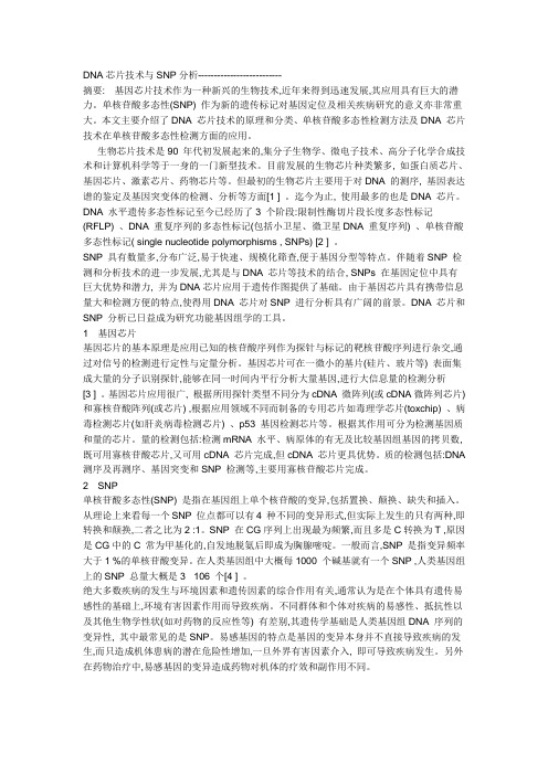
DNA芯片技术与SNP分析--------------------------摘要: 基因芯片技术作为一种新兴的生物技术,近年来得到迅速发展,其应用具有巨大的潜力。
单核苷酸多态性(SNP) 作为新的遗传标记对基因定位及相关疾病研究的意义亦非常重大。
本文主要介绍了DNA 芯片技术的原理和分类、单核苷酸多态性检测方法及DNA 芯片技术在单核苷酸多态性检测方面的应用。
生物芯片技术是90 年代初发展起来的,集分子生物学、微电子技术、高分子化学合成技术和计算机科学等于一身的一门新型技术。
目前发展的生物芯片种类繁多, 如蛋白质芯片、基因芯片、激素芯片、药物芯片等。
但最初的生物芯片主要用于对DNA 的测序, 基因表达谱的鉴定及基因突变体的检测、分析等方面[1 ] 。
迄今为止, 使用最多的也是DNA 芯片。
DNA 水平遗传多态性标记至今已经历了3 个阶段:限制性酶切片段长度多态性标记(RFLP) 、DNA 重复序列的多态性标记(包括小卫星、微卫星DNA 重复序列) 、单核苷酸多态性标记( single nucleotide polymorphisms , SNPs) [2 ] 。
SNP 具有数量多,分布广泛,易于快速、规模化筛查,便于基因分型等特点。
伴随着SNP 检测和分析技术的进一步发展,尤其是与DNA 芯片等技术的结合, SNPs 在基因定位中具有巨大优势和潜力, 并为DNA芯片应用于遗传作图提供了基础。
由于基因芯片具有携带信息量大和检测方便的特点,使得用DNA 芯片对SNP 进行分析具有广阔的前景。
DNA 芯片和SNP 分析已日益成为研究功能基因组学的工具。
1 基因芯片基因芯片的基本原理是应用已知的核苷酸序列作为探针与标记的靶核苷酸序列进行杂交,通过对信号的检测进行定性与定量分析。
基因芯片可在一微小的基片(硅片、玻片等) 表面集成大量的分子识别探针,能够在同一时间内平行分析大量基因,进行大信息量的检测分析[3 ] 。

SNP开发/验证的研究方法和技术路线1分子标记:分子标记,我想这部分是我们分子标记组最核心的任务。
现在,我们没有任何可用的标记检测我们的定位材料。
即使想要验证已经定位的QTLs,我们也需要相对应的区间内的分子标记,尤其是SNP标记。
1.1 全基因组SNP—Affymetrix芯片:一套完整的全基因组的SNP芯片,相对于Douglas体系,其操作简单,高通量。
可以直接对定位群体进行初定位的扫描或是对育种材料的背景进行分析。
在国家玉米改良中心,有一套3k 的Illumina芯片,就是用来对玉米材料进行高通量检测,基因型检测结果通常可以用来QTLs 初定位,育种材料的群体划分与纯度鉴定以及低密度的关联分析等。
在此,我建议我们应该开发一套番茄基因型检测的芯片。
目前,只是查找到Illumina芯片有一套全基因SNP信息,包含7,720条探针.而Affymetrix 公司目前并没有相应的产品.但是通过跟Affymetrix公司了解,可以利用Illumina芯片已有的结果进行开发。
番茄目前测序结果显示其全基因组大小为~760Mb,而玉米为~2,500Mb,但是他们包括的基因数目~30,000个,整体情况相近。
另外,番茄作为自交植物,其LD的衰减值应该更大,有效的历史重组会更少,遗传多样性低.因此,综合考虑,我建议我们可以开发~3k芯片,应该可以满足大多数研究材料、育种材料的基因型检测需求。
虽然目前下一代测序技术蓬勃发展,但是对于用于基因型检测来讲,其数据分析与成本相对于芯片都要更复杂和更高。
总之,我们番茄处于刚刚发展阶段,我认为就基因型检测方面,芯片有其很高的应用价值。
即使像玉米,这样测序技术发展很多年的材料,芯片技术也在应用。
1.2全基因组SNP—Douglas:当用Affymetrix芯片检测鉴定完番茄基因型并完成基因型分析之后,1)对于优良的QTLs 或是基因,我们可以直接选择覆盖整个区间的分子标记运行Douglas系统进行分子标记辅助育种,2)对于需要进一步验证的QTLs,我们也可以利用Douglas系统只检测材料覆盖定位区间的基因型,而不需要再一次利用Affymetrix芯片或是其他方法进行全基因检测(图1.1)。

利用SNP芯片构建我国冬油菜参试品种DNA指纹图谱赵仁欣;易斌;李森业;郭瑞星;曾新华;文静;马朝芝;沈金雄;涂金星;傅廷栋【期刊名称】《作物学报》【年(卷),期】2018(044)007【摘要】以 2016-2017 年度 187 份国家油菜参试品种及 2015-2016 年度 33份续试品种为材料, 利用油菜 60K Il-lumina Infinium SNP (single nucleotide polymorphism)芯片进行基因分型, 得到52157个SNP标记.按照分型为AA和BB频率不为0、最小基因型频率(minor freq)大于0.05、SNP得率(call freq)大于0.80、样品缺失率小于5%及分型明晰的要求筛选出5374个SNP标记.这些标记的PIC (polymorphism information content)均值为0.27, PIC值大于0.25的SNP标记占55.94%.其中有5143个SNP标记能对应到A1~A10、C1~C9连锁群上, 且比较全面地覆盖了油菜的基因组.用PowerMarker、MEGA等软件对224份样品的5374个标记分析, 结果显示: (1)设置8个品种重复2次点样对照, 得出Infinium 芯片的技术误差为 0.36%, 与 Illumina 公司公布的 0.1%的技术误差十分接近. (2) NJ(Neighbor-joining)聚类分析中, 97.86%的区试品种的相似系数小于95%、87.88%的续试品种相似系数大于95%, 相似系数95%可作为品种特异性及一致性鉴定的阈值.这5374个 SNP标记在油菜全基因组上分布均匀、多态性高、区分度好, 可用于甘蓝型油菜品种特异性和一致性的鉴定分析及甘蓝型油菜品种DNA指纹图谱构建的研究.%Using the Brassica 60K Infinium SNP (single nucleotide polymorphism) array, a total of 52157 SNP markers were obtained by genotyping 33 annual test varieties in 2015–2016 and 187 varieties in 2016–2017. A total of 5374 high quality SNPs were retainedafter removing SNPs with AA or BB frequency = 0, main gene frequency <0.80, secondary gene frequency < 0.05, sample loss rate > 0.50, or SNPs that did not show clearly defined clusters. The mean PIC (polymorphism information content) value of selected 5374 markers was 0.27, SNPs with the PIC value >0.25 accounted for 55.94% of total number. Among 5374 SNPs, 5143 corresponded to the A1–A10 and C1–C9 linkage groups, and covered the rapeseed genome. We analyzed 5374 SNPs from 224 samples with softwares like PowerMarker and MEGA, etc. The technical error of the SNP array was 0.36%, when comparing two replicates of eight samples. It was close to the 0.1% technical error announced by Illumina. TheNJ(Neighbor-joining) cluster analysis revealed that 97.86% of the tested varieties had a similarity coefficient of less than 93%, 87.88% renewed varieties had a similarity coefficient of greater than 95%, which could be further used as criteria for the varietal specificity and the annual consistency assessment. The 5374 SNP markers screened in this study were highly polymorphic and evenly distributed in the rapeseed genome, and could be used for future variety identification and the construction of DNA fingerprinting.【总页数】10页(P956-965)【作者】赵仁欣;易斌;李森业;郭瑞星;曾新华;文静;马朝芝;沈金雄;涂金星;傅廷栋【作者单位】华中农业大学植物科学技术学院/作物遗传改良国家重点实验室, 湖北武汉 430000;华中农业大学植物科学技术学院/作物遗传改良国家重点实验室, 湖北武汉 430000;华中农业大学植物科学技术学院/作物遗传改良国家重点实验室,湖北武汉 430000;中国农业科学院油料作物研究所, 湖北武汉430062;中国农业科学院油料作物研究所, 湖北武汉430062;华中农业大学植物科学技术学院/作物遗传改良国家重点实验室, 湖北武汉 430000;华中农业大学植物科学技术学院/作物遗传改良国家重点实验室, 湖北武汉 430000;华中农业大学植物科学技术学院/作物遗传改良国家重点实验室, 湖北武汉 430000;华中农业大学植物科学技术学院/作物遗传改良国家重点实验室, 湖北武汉 430000;华中农业大学植物科学技术学院/作物遗传改良国家重点实验室, 湖北武汉 430000【正文语种】中文【相关文献】1.甘蓝SNP标记开发及主要品种的DNA指纹图谱构建 [J], 李志远;于海龙;方智远;杨丽梅;刘玉梅;庄木;吕红豪;张扬勇2.2013-2015年中国冬油菜参试品种(系)DNA指纹数据库的初步构建及分析 [J], 许鲲;吴金峰;李锋;陈碧云;高桂珍;闫贵欣;乔江伟;黄邦全;伍晓明3.利用SSR标记构建我国亚麻品种DNA指纹图谱及遗传多样性分析 [J], 潘根;邓勇;李德芳;张义;赵立宁;陈安国;李建军;黄思齐;唐慧娟;常丽;张翠萍4.利用SNP芯片构建甘蓝型油菜高密度遗传连锁图谱及含油量性状QTL分析 [J], 俎峰; 赵凯琴; 张云云; 原小燕; 田正书; 贺斌; 奚俊玉; 束正齐; 符明联5.利用中芯一号SNP芯片检测隆林猪全基因组拷贝数变异 [J], 路玉洁;莫家远;朱思燃;杨丽丽;陈奎蓉;吕冬玲;李月月;刘笑笑;梁靓;兰干球;梁晶因版权原因,仅展示原文概要,查看原文内容请购买。
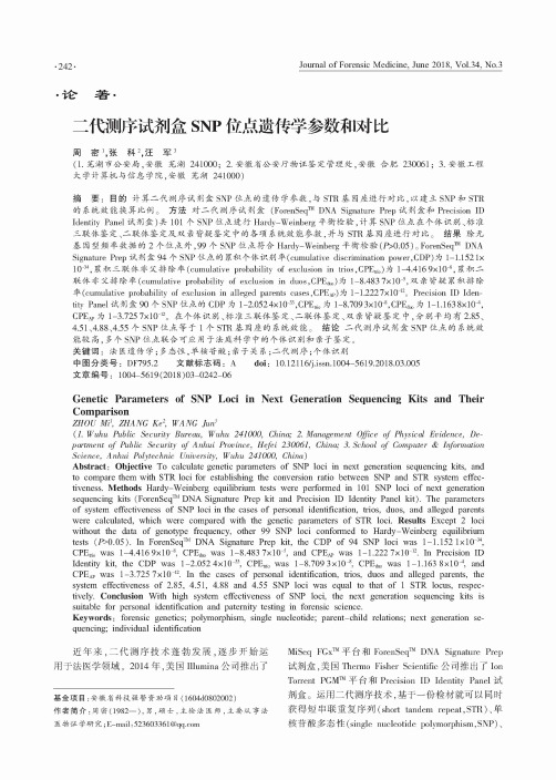
•论著•二代测序试剂盒SNP位点遗传学参数和对比周密!,张科",汪军3(1.芜湖市公安局,安徽芜湖241000;2.安徽省公安厅物证鉴定管理处,安徽合肥230061;3.安徽工程大学计算机与信息学院,安徽芜湖241000)摘要:目的计算二代测序试剂盒SNP位点的遗传学参数,与STR基因座进行对比,以建立SNP和STR 的系统效能换算比例。
方法对二代测序试剂盒(ForenSeq™ DNA Signature P rep试剂盒和Precision ID Identity Panel试剂盒(共101个SNP位点进行Hardy-Weinberg平衡检验,计算SNP位点在个体识别、标准 三联体鉴定、二联体鉴定及双亲皆疑鉴定中的各项系统效能参数,并与STR基因座进行对比。
结果除无 基因型频率数据的2个位点外,99个SNP位点符合Hardy-Weinberg平衡检验(fG0.05)*ForenSeq™ DNA Signature Prep 试剂盒 94 个 SNP 位点的累积、个体识别率(cumulative discrimination power,CDP)为1-1.1521X 10⁻³⁴,累积、三体非父排除率(cumulative probability of exclusion in trios,CPE t r i o)1-4.4169x10'累积、二联体除率(cumulative probability of exclusion in duos,CPE d u o)为1-8.483 7x10⁻⁵,双亲皆疑累积、排除率(cumulative probability of exclusion in alleged parents cases,CPE A P)为1-1.2227x10⁻¹²。
Precision ID Identity Panel 试剂盒 90 个 SNP 位点的CDP 为1-2.0524x10⁻³³,CPE t n o1-8.709 3x10⁻⁸,CPE d u o为1-1.163 8x10' CPE a p1-3.725 7x10-12。
Preliminary Data Sheet, May 2001FOA2322A3.2Gbit/s Laser Driver IC for Telecom and Datacom ApplicationsICs for CommunicationsEdition 2001-05Published by Infineon Technologies AG,St.-Martin-Strasse 53,D-81541 München, Germany© Infineon Technologies AG 2001.All Rights Reserved.Attention please!The information herein is given to describe certain components and shall not be considered as warranted characteristics.Terms of delivery and rights to technical change reserved.We hereby disclaim any and all warranties, including but not limited to warranties of non-infringement, regarding circuits, descriptions and charts stated herein.Infineon Technologies is an approved CECC manufacturer.InformationFor further information on technology, delivery terms and conditions and prices please contact your nearest Infineon Technologies Office in Germany or our Infineon Technologies Representatives worldwide.WarningsDue to technical requirements components may contain dangerous substances. For information on the types in question please contact your nearest Infineon Technologies Office.Infineon Technologies Components may only be used in life-support devices or systems with the express written approval of Infineon Technologies, if a failure of such components can reasonably be expected to cause the failure of that life-support device or system, or to affect the safety or effectiveness of that device or system. Life support devices or systems are intended to be implanted in the human body, or to support and/or maintain and sustain and/or protect human life. If they fail, it is reasonable to assume that the health of the user or other persons may be endangered.Preliminary Data Sheet, May 2001FOA2322A3.2Gbit/s Laser Driver IC for Telecom and Datacom ApplicationsICs for CommunicationsFor questions on technology, delivery and prices please contact the Infineon Technologies Offices in G ermany or the Infineon Technologies Companies and Representatives worldwide: see our webpage at FOA2322ARevision History:2001-05Previous Version:PageSubjects (major changes since last revision)FOA2322ATable of Contents Page 1Overview . . . . . . . . . . . . . . . . . . . . . . . . . . . . . . . . . . . . . . . . . . . . . . . . . . . 2 1.1Features . . . . . . . . . . . . . . . . . . . . . . . . . . . . . . . . . . . . . . . . . . . . . . . . . . . . 2 1.2Applications . . . . . . . . . . . . . . . . . . . . . . . . . . . . . . . . . . . . . . . . . . . . . . . . . 2 1.3Technology . . . . . . . . . . . . . . . . . . . . . . . . . . . . . . . . . . . . . . . . . . . . . . . . . 2 1.4General . . . . . . . . . . . . . . . . . . . . . . . . . . . . . . . . . . . . . . . . . . . . . . . . . . . . 22Electrical Characteristics . . . . . . . . . . . . . . . . . . . . . . . . . . . . . . . . . . . . . 5 2.1Absolute Maximum Ratings . . . . . . . . . . . . . . . . . . . . . . . . . . . . . . . . . . . . . 5 2.2General Operating Conditions . . . . . . . . . . . . . . . . . . . . . . . . . . . . . . . . . . . 6 2.3Characteristics and Operating Conditions . . . . . . . . . . . . . . . . . . . . . . . . . . 7 2.4Typical Characteristics of Temperature Compensation (Mode 1) . . . . . . . 14 2.4.1Modulation Current Swing versus R MOD, R TC,Junction Temperature and Supply Voltage / High Current Drive . . . . . . 14 2.4.2Modulation Current Swing versus R MOD, R TC,Junction Temperature and Supply Voltage / Low Current Drive . . . . . . 16 2.5Principle of Modulation Current Control by Using a Pilot Signal (Mode 2) 18 2.6Data / Clock Input Stage . . . . . . . . . . . . . . . . . . . . . . . . . . . . . . . . . . . . . . 19 2.7Timing of Clock and Data . . . . . . . . . . . . . . . . . . . . . . . . . . . . . . . . . . . . . 19 2.8Laser and V CC Supervising Circuit . . . . . . . . . . . . . . . . . . . . . . . . . . . . . . 20 2.9Input Signal Monitoring and Hardware Alarm(Consideration in absence of Laser Fault) . . . . . . . . . . . . . . . . . . . . . . . . . 21 3Pin Description . . . . . . . . . . . . . . . . . . . . . . . . . . . . . . . . . . . . . . . . . . . . 22 3.1Pad Layout . . . . . . . . . . . . . . . . . . . . . . . . . . . . . . . . . . . . . . . . . . . . . . . . . 26 4Application Examples . . . . . . . . . . . . . . . . . . . . . . . . . . . . . . . . . . . . . . . 28FOA2322A 3.2Gbit/s Laser Driver IC for Telecom and DatacomApplicationsFOA2322A1Overview1.1Features•Data rate up to 3.2Gbit/s•Supply range from +3.0V to +5.5V•Modulation current adjustable up to 75mA•Bias current adjustable up to 80mA•Choice between temperature compensation and integrated Two-Loop-Control of bias and modulation current•Integrated laser supervisor•Monitor output for optical output power1.2Applications•Fiber optics telecom and data communication systems•SDH / SONET, Fiber Channel, Gigabit Ethernet1.3Technology•Bicmos B6HFC1.4GeneralThis document defines the ratings and characteristics of a laser driver circuit dedicated for applications within telecom and datacom modules with respect to various transmission standards and laser safety requirements. A block diagram of this circuit is shown in Figure1.Modulation Control / Modulator / Input StageThe modulator is capable of driving modulation currents up to 75mA. There are two modes for adjusting the modulation current:Mode 1: The modulation current is adjusted by an external resistor (R MOD). The IC has an internal temperature compensation circuit for compensating the temperature characteristic of laser diode slope efficiency. With the external resistor (R TC) the modulation current temperature coefficient is adjustable. The temperature input itself is derived from chip junction temperature.Mode 2: The modulation current is controlled by using a low frequency pilot signal. The controller cutoff frequency is adjustable by external capacitor (C MOD). Mode 2 is suitable for data rates 1.25Gbit/s (depending on laser diode).There is an option for using data input latch.Input Signal MonitorAn input signal monitor circuit delivers a logic signal HWA and an internal signal which is used for laser disabling if data input is constantly high or low.Bias Control / Bias GeneratorThe bias controller controls the LD optical output power by adjusting the bias current. The controller cutoff frequency is adjustable by external capacitor (C BIAS). A min. cutoff frequency is integrated. The laser bias current will start at < 500µA after laser enable. Laser Supervisor / V CC SupervisorThe laser supervisor circuit monitors the laser output power by the means of monitor diode feedback. The voltage generated by monitor diode circuit is compared to a reference. If the input voltage deviates more than ±2dB (optical power ±1dB) from this reference the laser diode is switched off and a fault indication is generated. The V CC supervisor monitors the circuit power supply and switches off the laser if the V CC level is below the reset threshold. It is keeping the laser output down for the adjusted delay time (power on delay) after V CC has risen above the V CC reset threshold.Figure1General Circuit Block Diagram –Number of pins: 42–IC available as die2Electrical Characteristics2.1Absolute Maximum RatingsAbsolute Maximum Ratings which may not be exceeded to the device without causing permanent damage or degradation. Exposure to these values for extended periods may effect device reliability. If the device is operated beyond the range of Operating Conditions and Characteristics functionality is not guaranteed. All voltages given within this data sheet are referred to V EE if not otherwise mentioned.Table1Absolute Maximum RatingsParameter Sym-bolLimit Values Unit Condi-tions min.max.Supply Voltage-0.36V–Output Voltage at O, ON V CC - 2.6V CC + 0.3V1) Output Voltage at MPOUT-0.3V CC + 0.3V1)2) Output Voltage at Logic Output LF, HWA-0.3V CC + 0.3V1) Output Voltage at IBIAS-0.3V CC + 0.3V1)2) Input Voltage at Logic Inputs LEN, RST,RSTN, CSELN-0.3V CC + 0.3V1)Differential Data Input Voltage|V D - V DN|– 2.5V–Differential Data Input Voltage|V CLK - V CLKN|– 2.5V–Sink Current at Logic Output LF, HWA–5mA–Source Current at LDOFF-4–mA–Source Current at RPOUT-2–mA–Modulation Current at O, ON(both Outputs)–80mA–Bias Current at IBIAS–95mA–Modulation Control Sink Current at VMOD(Input Current for Current Mirror 1:10)–9.6mA–Bias Control Sink Current at VBIAS(Input Current for Current Mirror 1:25)– 4.8mA–Modulation Current Adjust Resistor R MOD800–Ω–Note:Stresses above the ones listed here may cause permanent damage to thedevice. Exposure to absolute maximum rating conditions for extended periods may affect device reliability.2.2General Operating ConditionsUnder the below defined operating conditions all specified characteristics will be met unless otherwise noted.Modulation Temperature Coefficient Resistor R TC50–Ω–Junction Temperature -40125°C –Storage Temperature-55150°C –Relative Humidity (non-condensing)–95%–Electrostatic Discharge Voltage Capability–1kV–1)Maximum voltage is 6V.2)For applications with V CC +5V (please refer to Figure 13).Table 2General Operating ConditionsParameterSym-bol Limit ValuesUnit Condi-tionsmin.max.Environmental Junction Temperature-40125°C1)1)For modulation current I OH ≤ 50mA-401102)2)For modulation current 50mA < I OH ≤ 75mA Relative Humidity (non-condensing)–95%–Supply VoltageV CC Range3 5.5V3)3)Valid for V CCA and V CCD ; V CCA ≥ V CCDTable 1Absolute Maximum Ratings (cont ’d)ParameterSym-bol Limit ValuesUnit Condi-tions min.max.2.3Characteristics and Operating Conditions Table3Characteristics and Operating ConditionsSP Parameter Sym-bolLimit Values Unit Condi-tion min.typ.max.Modulator / Modulation Control1Data Transmission Rate DR0– 2.5Gbit/s1) 2Supply Current I CC–3063mA2)3)3Modulation Current High at O/ONfor V CC=3.3Vfor V CC=5V I OH -I OL55––6575mA4)5)4Modulation Current Low at O/ON I OL0–2mA6)Offset5Modulation Current atLaser Shut DownI OSD0–200µA7)6O, ON Output Voltage Rangefor V CC=3.3Vfor V CC=5V V O,V ONV CC-1.65VV CC-2.0V––V CCV CCV8)7Modulation Current AdjustResistor Range(MOD-Resistor)R MOD800–Open InputΩ9)10)8Modulation TemperatureCoefficient ResistorRangeR TC50–Open InputΩ9)11)Serial Data/Clock Input9Data Input Voltage High V IHD––V CCD V–10Data Input Voltage Lowfor V CCD=3.3Vfor V CCD=5V V ILD1.02.2––––V–11Data Input Voltage Swing|V D -V DN|250–1600mV–12Clock Input Voltage High V IHCLK––V CCD - 0.65V–13Clock Input Voltage Lowfor V CCD=3.3Vfor V CCD=5V V ILCLK1.02––––V–14Clock Input Voltage Swing |V CLK -V CLKN|250–1100mV–15Bias Voltage at D/DN V BBD–V CCD - 1.0–V12) 16Bias Voltage atCLK/CLKNV BBC–V CCD - 1.3–V12)17Differential Data/ClockInput TerminationR IN80100120Ω12)13)19Input CapacitanceD/DN/CLK/CLKNC IN––0.6pF–20Setup Time (Data/Clock)t SETUP–20–ps–21Hold Time (Data/Clock)t HOLD–20–ps–22Eye Opening at2.5Gbit/s (w. Latch)t EO–360–ps–Input Signal Monitor (ISM)23Internal ISM cutofffrequencyf ISM165238372kHz14)24Cutoff frequency of ISM with external C ISM f ISM(6.1µs+84kΩ×C ISM)-1(4.2µs+70kΩ×C ISM)-1(2.7µs+56kΩ×C ISM)-114)15)25Internal ILM cutofffrequencyf ILM–160–kHz14)26Cutoff frequency of ILMwith external C ILM=1nFf ILM–73–kHz14)15)27Duty Cycle for laserenable25–75%–28Duty Cycle for laser disable 0–5%Inputlow29Duty Cycle for laser disable 95–100%InputhighTable3Characteristics and Operating Conditions (cont’d)SP Parameter Sym-bolLimit Values Unit Condi-tion min.typ.max.Laser Power Control30Bias Current I IBIASmax0–80mA–31Start Bias Current I IBIASmin––500µA–32Bias Current at LaserShut DownI IBIASSD––500µA–33Output Voltage RangeIBIASV IBIAS0.5–V CC V–34Power Monitor Current I MPOUT0V MDR POUT1mA16)35Output Voltage Range MPOUT V MPOUT V RPOUT +0.5–V CC V–36Resistor Range RPOUT R POUT 2.4–Open Input kΩ–37Output Voltage RangeRPOUTV RPOUT0V MD V CC - 1.2V–38Internal cutoff frequencyof bias controllerf BIAS233762kHz17)39Cutoff frequency of bias controller with externalC BIAS f BIAS(44µs+306kΩ×C BIAS)-1(27µs+204kΩ×C BIAS)-1(16µs+131kΩ×C BIAS)-115)17)40Conversion gain of biasgeneratorG BIAS–100–mA/V–Laser Supervising Circuit41MD Failure Voltage High–V MDnom+1.5dB V MDnom+2dB18)42MD Failure Voltage Low V MDnom-2dB V MDnom-1.55dB–18)43MD Range without Failure Recognition V MDnom-1.2dB–V MDnom+1.2dBV19)44Internal FailureRecognition Timet FDEL386086µs17)20)45Additional FailureRecognition Time byexternal C FDEL t FDEL C FDEL×0.7µs/pFC FDEL×1.0µs/pFC FDEL×1.3µs/pF15)17)20)Table3Characteristics and Operating Conditions (cont’d)SP Parameter Sym-bolLimit Values Unit Condi-tion min.typ.max.46Shut Off Time after LFtransition or Laser Disablet LDdis0–3µs21)47V CC Reset Threshold forLaser Enable/Disable2.5 2.75 2.99V22) 48Internal Power On Delay t PDEL213333480µs23)49Additional Power On Delay by external C OSC t PDEL64 ×C OSC×138kΩ64 ×C OSC×173kΩ64 ×C OSC×208kΩ15)23)50LDOFF low Output Current 1.5–4mA sinkcurrent51LDOFF high Output Current ––2µA sinkcurrent52LDOFF high OutputVoltageV CC-0.1––V–53LDOFF low Output Voltage V CC-2.0–V CC-1.2V withoutexternalloadReference Voltage54MD Reference Value V MDR 1.12– 1.32V24)55V MDR Drift overTemperature Range |∆V MDR/V MDR|––5%–56V MDR Drift over Supply Voltage Range3V…5.5V |∆V MDR/V MDR|––10%–57V MDR Drift overTemperature Range atSupply Voltage Range3V…3.6V |∆V MDR/V MDR|––5%–58V MDR Drift overTemperature Range atSupply Voltage Range4.7V…5.3V |∆V MDR/V MDR|––5%–Table3Characteristics and Operating Conditions (cont’d)SP Parameter Sym-bolLimit Values Unit Condi-tion min.typ.max.Logic Inputs RSTN, RST, LEN59Input Voltage High V IHLOGIC 2.0–V CC V25) 60Input Voltage Low V ILLOGIC0–0.8V25) 61Input Current High I IHLOGIC––5µA–62Input Current Low I ILLOGIC-5––µA–Logic Inputs CSELN63Input Voltage High fordisabling data input latch(nonclocked mode) or letCSELN openV IHLOGIC 2.2–V CC V–64Input Voltage Low forenabling data input latch(clocked mode)V ILLOGIC0–0.8V–65Internal Pull-Up-Resistor R CSELN81012kΩ–Logic Outputs LF, HWA66Output Voltage Low V OLLOGIC––0.4V–67Output Current High (Leakage Current)I OHLOGIC––100µA opencollector68Output Current Low I OLLOGIC2––mA sinkcurrent Modulation Control (Mode2)69Mode 1 select V MODE V CC-0.8–V CC V–70Mode 2 select V MODE0–0.8V–71Internal pilot frequency f PILOT7.71217.3kHz–72Pilot frequency with external C OSC f PILOT(130µs+16 ×C OSC× 208kΩ)-1(83µs+16 ×C OSC× 173kΩ)-1(58µs+16 ×C OSC× 138kΩ)-115)73Effective pilot currentamplitude on modulationcurrent high level (default)am PILOT– 3.5–%26)Table3Characteristics and Operating Conditions (cont’d)SP Parameter Sym-bolLimit Values Unit Condi-tion min.typ.max.74Pilot current amplitude on bias current (default)ab PILOT– 5.05–%26)75Cutoff frequency of modulation controller with external C MODf MOD(306k Ω×C MOD )-1(204k Ω×C MOD )-1(131k Ω×C MOD )-115)17)1)Measured into 25 Ω.2)The bias-, modulation-, the LF-, HWA- and MPOUT- output currents are not included.3)The typical supply current is defined for driving a laser with about 20mA bias current and about 20mA modulation current and a IC junction temperature of about 50°C and a V CC of 5V. The maximum supply current is defined for driving the upper limits of bias current and modulation current with worst case junction temperature and with a V CC of 5.5V (V CC =V CCA =V CCD ).4)This describes the AC modulation current (the DC component is the overall offset current). AC modulation current is drawn by O at V D > V DN , it is drawn by ON at V D < V DN . I OH refers to drawn modulation current (AC +DC). I OL refers to an inactive current output (DC current only).5)See Table 2 for operating conditions junction temperature.6)Inactive current output (see also 4)).7)Modulation current when the laser diode is disabled.8)Valid for V CC =V CCA =V CCD =5V. It is possible to increase the output voltage range for the V CC range of 5V ±0.5V of about 0.85V by using the Pad V CCD2 instead of V CCD (see Figure 14). The specified limits for data and clock inputs are valid for V CCD .9)Adjustment of programmable parameter by resistor value within this range (see Chapter 2.4).10)Adjusting the modulation current by R MOD notice that the decreasing of R MOD will increase the modulation current. R MOD in combination with R TC has to be adjusted that the modulation current is smaller than 50mA or 75mA respectively over specified temperature range. If R MOD -Pad is not connected (open input) there will be no modulation current at the output O/ON.11)Modulation current adaptation within junction temperature range. Low junction temperature represents a low additional modulation current. High junction temperature represents a high additional modulation current. If R TC -Pad is not connected there will be no noteworthy modulation current adaptation.12)Data/clock inputs are internally connected to V BBD /V BBC by resistor R 1/R 2 with a differential termination by R IN .See data input stage description (see Figure 9).13)The resistance is guaranteed for junction temperature 25°C.Table 3Characteristics and Operating Conditions (cont ’d)SP ParameterSym-bolLimit ValuesUnit Condi-tionmin.typ.max.14)If data input duty cycle falls below lower limit or exceeds upper limit the laser will be disabled by ISM circuit.On the other hand, the laser will be enabled whenever the data input duty cycle goes back to the allowed range.Data input duty cycle refers to the quotient given by number of ones divided by number of zeros within serial data stream. The ISM-circuit evaluates the mean value of the duty cycle (integrator). The cutoff frequency of ISM f ISM is defined for data pattern 1010…. In case of data frequency is to small the ISM circuit will disable the laser because of long High- or Low-series. The ISM-circuit can be deactivated by a 25kΩ resistor from CISM to V EE. The ILM-circuit additionally is used for ac-coupled data inputs. It works as a peak detector. The laser will be disabled if data are set to a static state. The cutoff frequency of ILM fILM is defined for data pattern 1010…. (Specified value is for data input voltage swing of 400mV).The ILM-circuit is direct AC-coupled to the data input. So the cutoff frequency depends on data input swing. The ILM-circuit can be deactivated by a short from CILM to V CC.15)A capacitor within this range programs the time (or frequency).16)Open collector output for pulling up a resistor to monitor the current.17)Difference and temperature drift of passive IC component parameters match to passive IC componentparameters in other circuit parts.18)The supervisor circuit will detect a failure condition if MD voltage exceeds VMDnom±2dB range. V MDnom is given by nominal voltage level at MD which is set by V MDR. The deviation is calculated with 20lg(V MD/V MDnom).The deviation of optical power is calculated with 10lg(V MD/V MDnom).19)The supervisor circuit will detect no failure condition if MD input voltage ranges from VMDnom -1.2dB toV MDnom+1.2dB. V MDnom is given by nominal voltage level at MD which is set by V MDR. The deviation is calculated with 20lg(V MD/V MDnom). The deviation of optical power is calculated with 10lg(V MD/V MDnom). 20)A failure condition will be reported by LF=H if this condition lasts for tFDEL. Minimal capacitor on CFDEL has to be chosen that the failure recognition time is longer than the setting time of the bias controller.21)Time between LF high (or LEN high) and LDOFF high.22)At supply voltages below VCC threshold the laser diode bias and modulation current will be held disabled and LDOFF will be held high. Above the laser diode will be enabled after the Power On Delay.23)The Power On Delay is the Reset time after VCC voltage has risen above the V CC reset threshold. During the Power On Delay the Laser diode bias and modulation current will be held disabled and LDOFF will be held high.24)Temperature and voltage drift are included.25)The minimal enable pulse width time for RST=L or RSTN=H or LEN=L has to be longer then tFDEL.26)Out of amPILOT and ab PILOT a factor K=ab PILOT/am PILOT can be defined, which is an important factor for the pilot control (for definition of am PILOT and ab PILOT see Figure8). For most laser diodes the optimum value of K is 1.44 (default value). If K is set close to factor2 the modulation current and jitter may increase. If K is set close to factor 1 the modulation current may decrease. In both cases a malfunction of laser control is possible.A resistor between V CC and RMRIP can be used for decreasing am PILOT. Further a resistor between V CC andRBRIP can be used for decreasing ab PILOT. So the factor K can be adjusted. For default factor K let RBRIP and RMRIP connected to V CC (=V CCA).2.4Typical Characteristics of Temperature Compensation (Mode 1)2.4.1Modulation Current Swing versus R MOD , R TC ,Junction Temperature and Supply Voltage / High Current DriveFigure 2F =I 100°C /I 0°C versus R TC , Parameter R MOD , V CCFigure 3I 0 versus T j , Parameter R MOD , R TC (V CC =3.3V)ITD11328-5010t˚C I O 20304050607080-30-101030507090130mA2 k Ω/700 Ω2 k Ω/200 Ω2 k Ω/2 k Ω4 k Ω/200 Ω4 k Ω/700 Ω4 k Ω/2 k Ω110Figure 4I 0 versus T j , Parameter R MOD , R TC (V CC =5.0V)ITD11329-500t˚C I O-30-101030507090130mA1020304050607080100 2 k Ω/700 Ω2 k Ω/200 Ω2 k Ω/2 k Ω4 k Ω/200 Ω4 k Ω/700 Ω4 k Ω/2 k Ω1102.4.2Modulation Current Swing versus R MOD , R TC ,Junction Temperature and Supply Voltage / Low Current DriveFigure 5F =I 100°C /I 0°C versus R TC , Parameter R MOD , V CCFigure 6I 0 versus T j , Parameter R MOD , R TC (V CC =3.3V)ITD1133018001.00F 1.051.101.151.201.251.301.402800380048005800680078009800R TCk Ω5 k Ω/3.3 V5 k Ω/5 V 10 k Ω/5 V 10 k Ω/3.3 V ITD11331-505t˚C I O -30-101030507090130mA6789101112131415161810 k Ω/2 k Ω10 k Ω/5 k Ω10 k Ω/9.5 k Ω5 k Ω/5 k Ω5 k Ω/2 k Ω5 k Ω/9.5 k Ω110Figure7I0 versus T j, Parameter R MOD, R TC (V CC=5.0V)2.5Principle of Modulation Current Control by Using a Pilot Signal (Mode 2)The DC-part of the monitor current controls the bias current. The difference of the optical low frequency AC-part ∆Ppp is used for the modulation current control. ∆Ppp is measured over the monitor current. The aim of the control is to settle ∆Ppp to Zero. (That means a part of the pilot current amplitude on bias current is modulated below laser current threshold. Therefore please take into account the laser characteristics, e.g.switch-on delay, for higher data rates.) Mode 2 can only be used for DC-coupled laser diodes.Figure 8Modulation Current Control by Using a Pilot Signal2.6Data / Clock Input StageData and clock inputs are terminated with 100Ω and are connected to a V BB reference by resistors R1/R2. (V BB for Clock input is V BBC, V BB for Data input is V BBD.) This easily provides the input reference voltage at AC coupling. A schematic of the input stage is shown below:Figure9Data/Clock Input Stage 2.7Timing of Clock and DataFigure10Timing of Clock and Data ITS11334PN RINR1R2ReferenceGeneratorVBBR 1, R2= 5 kΩRIN= 100 Ω ±20%2.8Laser and V CC Supervising CircuitIf there is a laser fault (optical power deviates ±1dB) this signal is stored and indicated by LF (logic high). The fault indication (LF) can be reset with low level at RSTN or with high level at RST or with power down (V CC < V CC Reset Threshold) only. After power up,LF will always be cleared. Disabling the laser by LEN does not influence a previous fault indication by LF. The laser fault generation can be switched off by connecting CFDEL to V CC . During RSTN is logic low or RST is logic high the circuit is in Reset state.In case of changing RST =H or RSTN =L after laser fault recognition LF =H (after t FDEL ) there is an additional delay time implemented which has the same value as the Power On Delay.If the supply voltage is lower than the V CC reset threshold the indicator Hardware Alarm (HWA) is still at the low level and the circuit is in Reset state.During Power On Delay the circuit is in Reset state too. The Power On Delay is defined as the delay after V CC voltage has risen above the V CC reset threshold. This time can be adjusted by an external capacitor at COSC (Mode 1). The Reset N-Output of the MAX 809S Power Supervisor IC can be connected to RSTN to use the reset function of the MAX 809S.The laser control by RST and RSTN is fully redundant. This means only an AND combination of RST =0 / RSTN =1 can switch the laser on. The OR combination of RST =1 / RSTN =0 switches the laser off (see Table 4 for clarification).Table 4 shows the static states of these signals. Dynamic changes or delays due toexternal delay capacitors are not shown.Table 4Laser Diode Currents Enable / Disable SignalsRST LEN RSTN In Case of Laser Fault V CC < Reset Threshold V CC LDOFF Modulation Enable 1)1)Internal signal Bias Enable 1)LF (highactive)X 1X 0X 10001X X X X 1000X X 0X X 1000X X X X yes 10000011no 2)2)After Power On Delay 13)3)After t FDEL0013)01no 2)04)4)Sink current enabled = Low11Bias current is disabled by setting Bias Enable low, modulation current is disabled by setting Modulation Enable low.LEN do not effect LF. This means LF can not be reset by LEN.2.9Input Signal Monitoring and Hardware Alarm(Consideration in absence of Laser Fault)Table5Function of ISM Circuit and Hardware Alarm Indicator (HWA)Data Level (after delay of ISM)V CC < ResetThreshold of V CC/Circuit in ResetstateISM LaserEnable1)1)Internal signal LDOFF HWA (lowactive)ModulationEnable1)BiasEnable1)Constant High No01000 Constant Low No01000 Constant High Yes01000 Constant Low Yes01000 Duty Cycle ok Yes11000 Duty Cycle ok No102)2)Sink current enabled = Low111。
SNP-2321/2322变压器差动保护单元使用说明书一、概述适用范围SNP-2321/2322变压器差动保护装置是用于110kV及以下电压等级的双圈、三圈变压器成套差动保护装置,其中,SNP-2321为三圈变压器差动保护装置,SNP-2322为两圈变压器差动保护装置,可集中组屏,也可在开关柜就地安装,全面支持变配电综合自动化系统。
功能及特点1.SNP-2321/2322差动保护单元主要功能◆差动速断保护◆比率差动保护◆二次谐波制动的差动保护◆CT断线报警及闭锁差动◆非电量保护2.辅助功能◆差流越限告警◆装置故障告警◆故障录波◆保护定值和时限的独立整定◆自检和自诊断3.测控功能◆电量测量(遥测量):高、(中)、低侧保护电流、差动电流、制动电流等◆遥信量:装置共有14路开入量4.通讯功能◆CAN总线,以及标准的RS485多机通讯接口5.特点◆采用分层分布式设计,可组屏安装或直接安装于开关柜上运行◆封闭、加强型单元机箱,抗强干扰设计,适用于恶劣环境,可靠性高、抗干扰能力强,符合IEC电磁兼容标准◆可以实现远方定值整定与修改◆事件顺序记录并上传SOE事件◆汉字液晶显示,键盘操作◆设有独立的起动元件用来开放继电器电源,提高装置的安全性二、基本原理 差动速断保护差动速断保护实质上为反应差动电流的过电流继电器,用以保证在变压器内部发生严重故障时快速动作于跳闸。
保护动作判据为:Id >Isdzd*高压侧额定电流式中Id 为差动电流,Isdzd 为差动速断电流定值(定值中设置为高压侧额定电流倍数)。
三相差流中任一相满足Id >Isdzd*高压侧额定电流,保护即出口动作。
(J1 J2 J3 )≥1RLP1跳主变高中低压侧差动速断A相差流>Isdzd B相差流>Isdzd C相差流>Isdzd比率差动采用常规比率差动保护,能可靠地躲过外部故障时的不平衡差动电流。
其动作方程如下: Id >Icdqd*高压侧额定电流 Id >Kb1*Ir式中:Id 为差动电流,Ir 为制动电流,Kb1为比率制动系数。
Icdqd 为差动电流启动定值(定值中设置为高压侧额定电流倍数)。
对于双圈变压器:Id =| Ih +I1 | , Ir =| Ih 一I1 |/2对于三圈变压器: Id =| Ih +I1+Im |Ir=max{|Ih | . |I1 | . | Im |} 其中Ih 、I1、Im 为变压器高、低、中压侧电流。
图2 比率差动保护的动作特性二次谐波制动的差动保护为了躲过变压器合闸瞬间的励磁涌流,本装置利用二次谐波作为励磁涌流闭锁判据,动作方程如下:比率制动动作区速断动作区 Kb1I d IsdzdIcdqd0 I cdqd/Kb1IrψψId Kxb Id *2>式中ψ2Id 为A 、B 、C 三相差动电流的二次谐波,ψId 为对应的三相差动电流,Kxb 为二次谐波制动系数。
只要有任一相满足上述条件,则闭锁三相比率差动保护。
&RLP2≥1B相差流>Icdqd C相差流>Icdqd A相差流>Icdqd ≥1C相差流>Ir*Kb B相差流>Ir*Kb A相差流>Ir*Kb RLP4跳主变高(中)低压侧比例差动比例差动启动比例制动(J1 J2 J3 )二次谐波电流>Kxb*差流CT断线条件图3 差动比率动作逻辑图变压器差动保护各侧电流相位差及平衡补偿1) 变压器各侧电流互感器二次均采用星型接线,其二次电流直接接入装置,从而简化了CT 二次接线,增加了电流回路可靠性,电流互感器各侧极性都以指向变压器为同极性端。
2) 变压器各侧CT 二次电流相位由软件自校正,凡是Y0/Y/△(或Y/△)接线方式,其Y 侧电流均须校正相位。
对于Y/Δ-11接线,校正方法如下:3/)('B A A I I I-=3/)('C B B I I I-=3/)('A C C I I I-=式中C B A I I I ,,为Y 侧CT 二次电流, C B A I I I ',','为校正后的各相电流3) 各侧电流互感器二次电流平衡补偿由软件完成,中、低压侧平衡均以高压侧二次电流为基准。
对容量为Se ,某侧额定电压为Ue 的变压器,设CT 变比为N,则相应二次额定电流为:NUe Sekjx Ie •=32其中Ie2为二次额定电流; kjx 为同型系数,这里kjx =1。
则高、中、低差流平衡系数计算如下:高压侧:KPH =H Ie H Ie 22 , 中压侧:KPM= M Ie H Ie 22 , 低压侧:KPL=LIe HIe 22 CT 断线报警及闭锁为防止CT 断线时,差动保护误动作,装置用软件设置了延时CT 断线报警及瞬时CT 断线闭锁保护功能。
* 延时CT 断线报警:当任一相差流大于dxbj(0.15Ie)的时间超过10秒时发出CT 断线告警信号,但不闭锁差动保护。
这也兼起保护装置交流采样回路的自检功能。
* 瞬时CT 断线报警:在故障测量程序中进行,满足下述任一条件不进行该CT 断线判别: 启动前某侧最大相电流小于dxlset(0.2Ie); 启动后最大相电流大于dxhset(1.2Ie)。
* 某侧电流同时满足下列条件认为是瞬时CT 断线: 只有一相电流为零(即小于dxminset(0.05Ie));其它相电流与起动前电流相等。
RLP11≥1A相差流>dxbj 10s延时CT断线报警B相差流>dxbj C相差流>dxbj图4 CT 断线逻辑图保护启动差动保护采用突变量启动元件,其特点是快速灵敏。
非电量保护非电量保护主要指从变压器本体引来的瓦斯信号、温度信号、油位信号、压力释放阀动作等现场信号经单元箱进行信号采集后,或动作于保护跳闸,或动作于报警,可通过控制字投退来控制。
告警&跳闸(J5,J6,J7)RLP91温度过高信号跳闸(J5,J6,J7)跳闸(J5,J6,J7)&6压力释放信号RLP7告警&3有载重瓦斯信号RLP6告警跳闸(J5,J6,J7)&告警2 本体重瓦斯信号RLP5异常告警装置异常:电源消失或自检出错(ROM 、RAM 、EPROM 定值检验出错),闭锁开出继电器。
测 量测量高、(中)、低侧电流、差动电流、制动电流等。
事件记录可以存储不少于60次的各项记录,包括事件日期、时间、事故电流(电压)、保护动作类型等,并可传送到管理系统或监控系统。
故障录波可以保存事故发生时的电流电压波形。
三、操作说明变压器差动保护测控单元的操作包括保护定值整定、保护功能投退、断路器分合操作以及测量数据显示等。
工作人员可以通过单元面板完成这些操作。
装置的面板由LCD显示器、LED指示灯及简易键盘组成。
LED 指示灯指示装置的工作状态及保护信号。
其中“24V”指示灯指示装置工作电源是否正常,正常运行时这个灯应常亮。
“运行”指示灯指示装置运行状态,正常运行时运行指示灯应有规律地闪动。
故障指示灯有3个,其中“事故”和“告警”指示灯分别表示有未复归的保护信号,“故障”指示灯指示装置通过自检发现有故障。
当保护动作或装置发生故障时,面板上相应的“事故”、“告警”、“故障”信号指示灯会亮,Ia= 260 AIb= 260 AIc= 260 Af= 50.00 Hz并在LCD显示器的最后一行显示保护动作或装置故障的类型。
请注意:此时显示的内容不表示事件发生的顺序。
若要进一步了解详细情况,可在主菜单中选择“事件记录”来查看事件顺01.保护投退02.保护定值03.事件记录04.输入输出05.采样数值06.实时时钟07.电能脉冲08.出厂设置09.设备信息10.退出序记录(SOE)。
装置的当地监控功能通过面板上的LCD显示器及简易的键盘操作实现。
LCD显示器为带背光的8*4汉字字符液晶显示模块,简易键盘由“↑”、“↓”、“→”、“←”、“退出”、“确认”及“复归”七个触摸键组成。
正常运行时液晶显示器自动循环显示各遥测量及一些保护模拟量的一次值。
若需查看未显示的项目,可按“↑”、“↓”键选择。
需要显示的项目可在“出厂设置”菜单下设定。
若需要复归保护动作或装置故障信号,可按下“复归”键,选择“是”后再按“确认”键即可。
按下“←”、“→”或“确认”键,LCD显示器则显示上图所示的主菜单。
通过“↑”、“↓”键可选择任一种功能,按“确认”键后进入该菜单的功能,按“退出”键或选择“退出”菜单则回到自动循环显示界面。
保护投退将光标移至“保护投退”并按“确认”键后,进入保护投退设置功能。
保护投退设置的界面如下图所示(以线路保护为例,不同的保护装置可能投退的项目不同)。
速断RLP01 投入速断方向RLP02 退出此时光标位于第1个投退项目即“速断”的投退设置。
通过按“↑”、“↓”键可选择其它投退项目。
当光标位于某一项目时,可通过“→”、“←”键来改变设置。
当全部投退项目设置完成后,可按“确认”键来保存这些设置。
按下“确认”键后,进入输入PASSWORD界面,如下图所示。
通过按“↑”、“↓”键可改变PASSWORD各位数字的值,通过按“→”、“←”键可选择要改变的位。
若用户没有修改过PASSWORD,则出厂默认的PASSWORD为1000(修改PASSWORD的方法见“保护定值”的使用方法)。
PASSWORD1:0000当输入正确的PASSWORD后,就将所修改的保护投退设置保存好了。
保护定值进入保护定值功能后,即可对装置整定值进行当地修改。
本装置可存贮三套定值。
“0”号定值为当前使用的定值套号(1、2或3),其余号定值为装置对应于0号定值的本套定值。
显示格式如下图。
保护定值套数00:001.00一次电流系数通过“↑”、“↓”键可选择显示或要修改的定值,按下“→”键进入光标所在定值的编辑状态。
在编辑状态下,通过“↑”、“↓”、“→”、“←”键可对定值进行编辑。
编辑完成后按“确认”键,在核实输入正确的口令后,再按“确认”键后本号定值修改有效,按“退出”键无效。
整定值定义及说明详见后面“定值清单”。
注:一次电压、电流系数*10后为实际的一次PT、CT变比。
事件记录本单元可存储不少于60次事件记录,其中第0号为最新记录,第1号为上一次记录,依次类推。
该记录存放在非易失性存贮器中,具有掉电长期保存功能,事件记录分开关变位、保护动作和装置故障三种类型。
事件记录显示格式如下图。
No.00 02-06-26时间11:21:22.525开关变位:开入3 分->合其中,No.后为记录号,02-06-26 为该事件发生的日期,即2002年6月26日。
11:21:22.525该事件发生的时间,即11时21分22秒525毫秒。