
nc后仿_综合后仿真
- 格式:ppt
- 大小:1.88 MB
- 文档页数:47

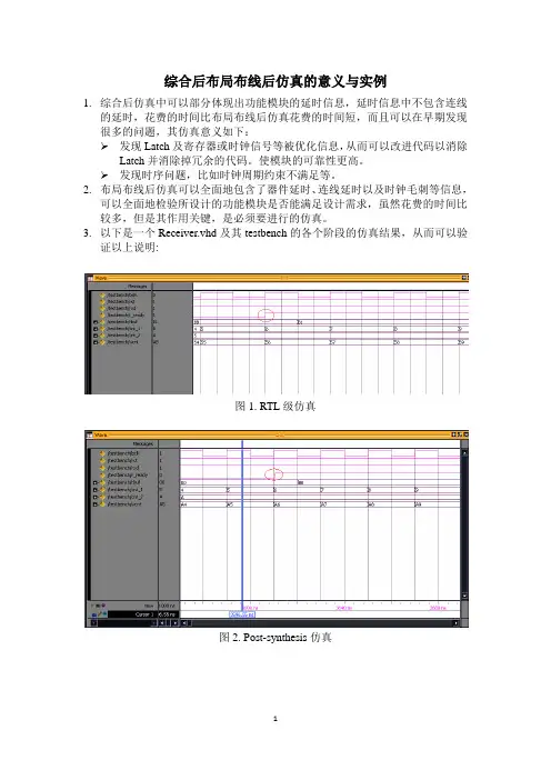
综合后布局布线后仿真的意义与实例1.综合后仿真中可以部分体现出功能模块的延时信息,延时信息中不包含连线的延时,花费的时间比布局布线后仿真花费的时间短,而且可以在早期发现很多的问题,其仿真意义如下:发现Latch及寄存器或时钟信号等被优化信息,从而可以改进代码以消除Latch并消除掉冗余的代码。
使模块的可靠性更高。
发现时序问题,比如时钟周期约束不满足等。
2.布局布线后仿真可以全面地包含了器件延时、连线延时以及时钟毛刺等信息,可以全面地检验所设计的功能模块是否能满足设计需求,虽然花费的时间比较多,但是其作用关键,是必须要进行的仿真。
3.以下是一个Receiver.vhd及其testbench的各个阶段的仿真结果,从而可以验证以上说明:图1. RTL级仿真图2. Post-synthesis仿真图3. Post-layout仿真从上图中可以看到,在RTL级仿真中,r_ready和rbuf信号分别和时钟上升沿以及时钟下降沿对齐,没有延时;在post-synthesis仿真中,r_ready和rbuf信号比时钟上升沿以及下降沿有了一点小的延时;而在post-layout仿真中,r_ready和rbuf信号比时钟上升沿以及下降沿有了很大的延时;从这里也能估计出,所设计的系统最大能达到的频率。
-------------------------------------------testbench.vhd--------------------------------library ieee;use ieee.std_logic_1164.all;use ieee.std_logic_unsigned.all;entity testbench isend testbench;architecture mtestbench of testbench iscomponent receiver is--generic(FRMLEN:integer:=9);Port (bclk,rst,rxd:in std_logic; --input signalr_ready:out std_logic; ---the receiver can accept data;rbuf:out std_logic_vector(7 downto 0));end component;signal bclk: std_logic:='0';signal rst,rxd: std_logic; --input signalsignal r_ready: std_logic; ---the receiver can accept data;signal rbuf: std_logic_vector(7 downto 0);signal cnt_1,cnt_2: std_logic_vector(3 downto 0);signal wcnt: std_logic_vector(7 downto 0);constant tclk: time:=20 ns;beginbclk<=not bclk after tclk/2;process(rst,bclk)beginif(rst='0')thenwcnt<=x"00";else if(bclk'event and bclk='1')thenwcnt<=wcnt+1;end if; end if;end process;cnt_1<=wcnt(3 downto 0);cnt_2<=wcnt(7 downto 4);receiver_0:receiverPort map(bclk=>bclk,rst=>rst,rxd=>rxd,r_ready=>r_ready,rbuf=>rbuf); processbeginrst<='0'; rxd<='1';wait for 300 ns;rst<='1';wait for 230 ns;rxd<='1';wait for 80 ns;rxd<='0'; ---16*20=320 ns----------------------------wait for 320 ns; ----320---1 bit for start bit------------11011101rxd<='1'; -----the byte is 11011101wait for 640 ns; ------2 bit for data bits----------------rxd<='0';wait for 320 ns; ------1 data bit----------------------rxd<='1';wait for 960 ns; ------3 bit for data bits----------------rxd<='0';wait for 320 ns; ------2 bit for data bits----------------rxd<='1'; ------1 bit for stop bit---------------wait for 960 ns;rxd<='0'; ---16*20=320 ns----------------------------wait for 320 ns; ----320---1 bit for start bit------------rxd<='1'; -----the byte is 11011101wait for 320 ns; ------1 bit for data bits----------------10001100rxd<='0';wait for 906 ns; ------3 data bit----------------------rxd<='1';wait for 604 ns; ------2 bit for data bits----------------rxd<='0';wait for 320 ns; ------2 bit for data bits----------------rxd<='1'; ------1 bit for stop bit---------------wait;end process;end mtestbench;----------------------------------Receiver.vhd-------------------------------------------- library IEEE;use IEEE.STD_LOGIC_1164.ALL;use IEEE.STD_LOGIC_ARITH.ALL;use IEEE.STD_LOGIC_UNSIGNED.ALL;entity receiver isgeneric(FRMLEN:integer:=9);Port (bclk,rst,rxd:in std_logic; --input signalr_ready: buffer std_logic; ---the receiver can accept data;rbuf:out std_logic_vector(7 downto 0));end receiver;architecture Behavioral of receiver istype states is (RS_ST,RS_CT,RS_WT,RS_SM,RS_SP); ----STATE OF TRANSITION signal pre_state,next_state:states;signal rxd_sync:std_logic;signal bclk_cnt:std_logic_vector(3 downto 0); --counter of baud clocksignal fbclk: std_logic; ----count flag of bclk;signal bit_cnt:std_logic_vector(3 downto 0);signal fbit: std_logic; ----count flag of bit counter,signal fsm: std_logic; -----flag of state sm;signal trbuf: std_logic_vector(7 downto 0);beginprocess(bclk,rst)beginif(rst='0')thentrbuf<="00000000";else if(bclk'event and bclk='0')thenif(fsm='1') then trbuf<=rxd_sync & trbuf(7 downto 1); end if; end if;end if;end process;process(bclk,rst)beginif(rst='0')thenrbuf<="00000000";else if(bclk'event and bclk='0')thenif(r_ready='1') then rbuf<=trbuf; end if; end if;end if;end process;pro1:process(rst,bclk,rxd) ----synchronize the rxd signal;beginif(rst='0')then rxd_sync<='1';else if(bclk'event and bclk='0') then ---change the value of rxd_sync at the falling edge----newrxd_sync<=rxd;end if; end if;end process;pro2:process(rst,bclk)beginif(rst='0') thenpre_state<=RS_ST;else if(bclk'event and bclk='1') thenpre_state<=next_state;end if;end if;end process;pro3:process(pre_state,rxd_sync,bclk_cnt,bit_cnt)beginfbit<='0'; r_ready<='0'; fbclk<='0'; fsm<='0';case pre_state is-----------state start---------------------------------------------when RS_ST=>-- fbclk<='0';-- fbit<='0';if(rxd_sync='0')thennext_state<=RS_CT;--- r_ready<='0';elsenext_state<=RS_ST;r_ready<='1';end if;-------------state center---------------------------------------------- when RS_CT=> if(bclk_cnt>="0100") thennext_state<=RS_WT;-- fbclk<='0';elseif(rxd_sync='1') thennext_state<=RS_ST;elsefbclk<='1';next_state<=RS_CT;end if;end if;--------------state wait---------------------------------------------when RS_WT=> if(bit_cnt>=FRMLEN)thenif(bclk_cnt>="1100")thennext_state<=RS_SP;-- -- fbclk<='0';-- fbit<='0';elsefbclk<='1';next_state<=RS_WT;end if;elseif(bclk_cnt>="1111")thennext_state<=RS_SM;fbit<='1';---fbclk<='0';elsenext_state<=RS_WT;-- fbit<='0';fbclk<='1';end if; end if;------------state_sample------------------------------------when RS_SM=> --rbuf(bit_cnt)<=rxd_sync;--fbit<='0';fsm<='1';fbclk<='1';next_state<=RS_WT;---------------state stop------------------------------------when RS_SP=> r_ready<='1';next_state<=RS_ST;---------------state others-----------------------------------when others=> next_state<=RS_ST;end case;end process;process(bclk,rst,fbclk) ---count process of bclkbeginif(rst='0')thenbclk_cnt<="0000";else if(bclk'event and bclk='1') thenif(fbclk='1') then bclk_cnt<=bclk_cnt+1; else bclk_cnt<="0000"; end if; end if; end if;end process;process(bclk,rst,fbit)beginif(rst='0')thenbit_cnt<="0000";else if(bclk'event and bclk='0') thenif(fbit='1') then bit_cnt<=bit_cnt+1; end if;if(bit_cnt>=FRMLEN)then bit_cnt<="0000"; end if;end if; end if;end process;---process(bclk,rst,bit_cnt)-- begin-- if(rst='0')then-- rbuf<="000000000";-- else if(bclk'event and bclk='0') then-- if(bit_cnt="0001" and fsm='1') then rbuf(1)<=rxd_sync; end if;-- if(bit_cnt="0010" and fsm='1') then rbuf(2)<=rxd_sync; end if;-- if(bit_cnt="0011" and fsm='1') then rbuf(3)<=rxd_sync; end if;-- if(bit_cnt="0100" and fsm='1') then rbuf(4)<=rxd_sync; end if;-- if(bit_cnt="0101" and fsm='1') then rbuf(5)<=rxd_sync; end if;-- if(bit_cnt="0110" and fsm='1') then rbuf(6)<=rxd_sync; end if;-- if(bit_cnt="0111" and fsm='1') then rbuf(7)<=rxd_sync; end if;-- if(bit_cnt="1000" and fsm='1') then rbuf(8)<=rxd_sync; end if;-- end if; end if;-- end process;end Behavioral;。

NC-Verilog仿真详解ncverilog仿真详解发表在ASIC/FPGA/汇编, 学习笔记, 编程开发 | 由阿布 | ⼗⼀⽉26, 2011 | 0标签: ncverilog, 仿真数位IC⼯具简介——Simulator ⼯具ModelSimModelSim是Mentor公司所推出的软体, 主要⽤来当作VHDL的模拟器, 也是⽬前CIC在VHDL⽅⾯的主要的模拟软体;但ModelSim不仅⽀援VHDL的模拟,同样也可⽤来当Verilog的模拟器, 更进⼀步的, ModelSim也⽀援VHD&Verilog的混合模拟, 这对於单晶⽚系统(SoC)的发展上, 矽智产(IP)是来源来⾃不同的地⽅, 有些矽智产是采⽤VHDL描述,有些是Verilog描述, 因此这是不可或缺的功能. 所以CIC引进ModelSim这⼀套软体.NCSimNC-SIM 为Cadence 公司之VHDL与Verilog混合模拟的模拟器(simulator),可以帮助IC 设计者验证及模拟其所⽤VHDL与Verilog混合计设的IC功能.NCVerilogNC-Verilog 为Cadence 公司之Verilog 硬体描述语⾔模拟器(simulator),可以帮助IC 设计者验证及模拟所设计IC 的功能.使⽤NC-Verilog软体,使⽤者必须使⽤Verilog 硬体描述语⾔的语法来描述所要设计的电路.VCSVCS 为Synopsys 公司之Verilog 硬体描述语⾔模拟器(simulator),可以帮助IC设计者验证及模拟所设计IC 的功能.使⽤VCS 软体,使⽤者必须使⽤Verilog 硬体描述语⾔的语法来描述所要设计的电路.ncverilog使⽤ncverilog是shell版的,nclaunch是以图形界⾯为基础的,⼆者调⽤相同内核;ncverilog的执⾏有三步模式和单步模式,在nclaunch中对应multiple step和single stepncverilog的三步模式为:ncvlog(编译) ncelab(建⽴snapshot⽂件) ncsim(对snapshot⽂件进⾏仿真)基于shell的ncverilog操作(尤其是单步模式)更适合于⼤批量操作ncverilog的波形查看配套软件是simvision,其中包含原理图、波形、信号流等查看⽅式三命令模式:ncvlog -f run.fncelab tb -access wrcncsim tb -gui第⼀个命令中,run.f是整个的RTL代码的列表,值得注意的是,我们需要把tb⽂件放在⾸位,这样可以避免出现提⽰timescale 的错误注意:ncvlog执⾏以后将产⽣⼀个名为INCA_libs的⽬录和⼀个名为worklib的⽬录第⼆个命令中,access选项是确定读取⽂件的权限。

基于AODV的NC算法及其仿真理论分析摘要Ad hoc网络是一种不依赖于基础设施的网络,由于其布网灵活,便捷等特点,在很多领域得到了广泛的应用。
无线网络多播研究的核心问题是无线多播路由算法和协议。
目前这方面的研究尚处于起步阶段,很多问题需要解决。
多播指的是同时把数据分组发送给网络中的一组主机。
多播通信对于网络有许多优点,多播减少从一个源节点或多个源节点发送相同的信息到多个目的节点的通信代价。
多播能节省网络的传输带宽、路由的处理时间和传输时延。
多播中的按需路由算法由于其优越的性能,因此在带宽受限的Ad hoc网络中应用比较广泛。
然而大部分算法只建立单路径路由,当一条链路失败时,只能发起新一轮的路由发现,从而降低网络性能。
AODV算法在网络开销和时延方面性能表现比较优越,但通过分析和仿真发现该算法有自身的弊端,及当链路连接失效时算法本身不具有自愈的能力。
我们此基础上针对Ad hoc网络提出了一种新的多路由算法——NC算法。
该算法有效的利用了AODV算法中中间节点收到的重复的RREP建立起多路径的路由,其优点是当一条链路失败时,节点可以从后备链路中选取一条链路而不会影响到其他的链路通信。
并且当路由发生断裂后,该算法可以进行本地修复,以保证多路径的数据通信。
实验结果表明我们建议的路由算法在路由延迟等方面比现有的AODV路由算法有更好的性能。
关键词Ad hoc网络AODV NC 多路径本地修复AbstractAd hoc is a network that do not depend on the network infrastructure. It has been widely used in many areas because of its flexible distribution , convenience and other characteristics.Based on the research of the Ad hoc routing protocols, this dissertation presents a comparative simulation study of on-demand protocols with the more traditional protocols on a common platform by using NS-2.AODV has predominant performance on network cost and time delay. However, through the analysis and simulation we found that the protocol has its own abuse. When the road linking fails, the protocol itself does not have the capacity to heal ourselves.On-demand routing in particular is widely developed in bandwidth constrained mobile wireless Ad hoc network because of its excellent performance. However, most proposed on-demand routing protocols use single path .These protocols need a new discovery whenever a path breaks and reduce network performance. We focus on AODV and propose an AODV-base new multicast routing protocol which named nodes count for mobile Ad hoc network. The protocol is using the repeating RREP which is incepted in AODV to build a multicast routing. The advantage of the routing is that the nodes will select a standby route when the path broken, and it does not affect the other. The protocol can ensure the communication by autochthonic repair to ensure the multicast communication.The experimental results show that the AODV improvement protocol achieves better performance in terms of delay than AODVKeywordsAd hoc network AODV NC Multicast Automatic repair目录前言 (1)第一章绪论 (2)1.1 Ad hoc概述 (2)1.2 Ad hoc产生的背景 (2)1.3 Ad hoc发展历程 (4)1.4 Ad hoc发展现状 (5)1.5 Ad hoc网络的应用 (6)1.6本章小结 (7)第二章 Ad hoc技术原理 (8)2.1无线Ad hoc网络的路由技术 (8)2.2 Ad hoc网络关键技术 (10)2.3 Ad hoc网络的特点 (13)2.4Ad hoc路由协议介绍 (14)2.5单播 (15)2.6多播 (16)2.7本章小结 (17)第三章基于AODV的NC算法 (18)3.1Ad hoc路由算法的概述 (18)3.2在 AODV中建立路由 (20)3.3 NC的路由建立过程 (20)3.4 NC算法的路由维持过程 (24)3.5 NC算法的路由表结构 (25)3.6本章小结 (26)第四章 NC算法的理论分析及仿真 (27)4.1 NC算法的独立性理论分析 (27)4.2 NC算法的仿真与结果分析 (28)4.2.1 仿真工具NS2简介 (28)4.2.2 仿真过程简述 (29)4.2.3 仿真环境的建立 (29)4.2.4 性能参数 (31)4.2.5 结果与分析 (31)4.3本章小结 (34)结论 (35)致谢 (36)参考文献 (37)附录: (39)一、仿真代码: (39)二、英文原文: (45)三、英文翻译: (49)前言Ad hoc网络是一种由若干无线通信设备自由组合形成的一种分布式无线分组网络,它不需要固定通信设备(如基站)的支持,不在彼此无线覆盖范围内的无线节点之间的通信可经中间节点的转发来完成。