modelsim和NCverilog的区别
- 格式:docx
- 大小:18.27 KB
- 文档页数:3
VHDL仿真,Verilog HDL仿真入门--ModelSim使用简介学硬件描述语言当然得实践,就得用软件仿真。
入门其实就是讲下仿真软件怎么用,是很简单的一件事,但是对于刚学的人来说可能有点无从下手。
我之前就有点迷茫,所以写这个入门当自己的笔记,也希望能给自学的新手有所帮助。
仿真VHDL和V erilog HDL并没有什么区别,一般的软件两种语言也都支持,仿真的步骤和方法也都是一样的。
常用的软件有Model Sim和Quartus II。
Quartus II功能很强大!实际的工作经常用它,它提供了功能仿真和时序仿真两种方式,但是作为学习HDL 并不方便,因为它compile编译的时候很慢,对于复杂的逻辑更是要很长时间。
好的一点是,Quartus II 编译后可以清楚的看到它使用了芯片的多少资源,各信号不同的延时等等。
另外,Quartus II编译后也可以调用第三方的仿真工具,如Model Sim进行仿真。
而Model Sim只完成逻辑功能的仿真,并不考虑具体使用什么器件,学习HDL或者设计逻辑的时候compile 一次所用的时间很短,便于调试找出逻辑的错误。
所以初学仿真推荐使用Model Sim。
本文也只讲下用Model Sim仿真逻辑的方法。
以下部分基本是参照软件帮助简写的,只是原来是英文的而且说的比较繁琐一些,也更详细内容更多。
详见Model Sim菜单Help--SE PDF Documentation--tutorial。
仿真有两种方法。
一种是Basic Simulation,就是直接建立库,然后编译源文件。
另一种是通过建立Project 来仿真,建立Project时软件会为它建立一个库,然后的仿真是一样的。
Basic Simulation的流程图如下下面详细写一个例子的步骤1. 建立库。
选择菜单File>New>Library。
建立新库就选a new library and a mapping to it,library name 和library physical name 都填work(当然其它名也行)。
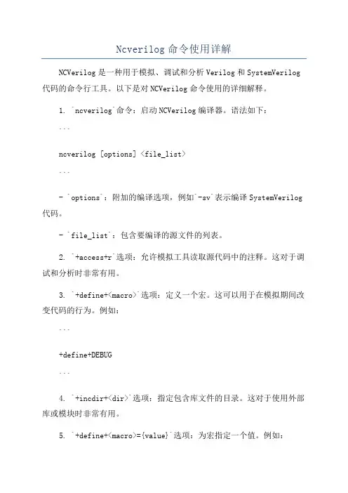
Ncverilog命令使用详解NCVerilog是一种用于模拟、调试和分析Verilog和SystemVerilog 代码的命令行工具。
以下是对NCVerilog命令使用的详细解释。
1. `ncverilog`命令:启动NCVerilog编译器。
语法如下:```ncverilog [options] <file_list>```- `options`:附加的编译选项,例如`-sv`表示编译SystemVerilog 代码。
- `file_list`:包含要编译的源文件的列表。
2. `+access+r`选项:允许模拟工具读取源代码中的注释。
这对于调试和分析时非常有用。
3. `+define+<macro>`选项:定义一个宏。
这可以用于在模拟期间改变代码的行为。
例如:```+define+DEBUG```4. `+incdir+<dir>`选项:指定包含库文件的目录。
这对于使用外部库或模块时非常有用。
5. `+define+<macro>={value}`选项:为宏指定一个值。
例如:```+define+WIDTH=8```6. `+libext+<ext>`选项:指定库文件的扩展名。
可以用于指定Verilog或SystemVerilog库文件的不同扩展名。
``````8. `+vcs`选项:指定使用VCS编译器的系统Verilog代码。
这对于一些特定的系统Verilog代码可能是必需的。
9. `-y <dir>`选项:指定一个目录,其中包含其他用户定义的Verilog或SystemVerilog库文件。
10. `-v <file>`选项:指定一个要编译的单独的库文件。
11. `-f <file>`选项:指定一个包含文件列表的文件。
这可以用于指定要编译的多个源文件。
12. `-fsmdebug`选项:在编译期间为FSM(有限状态机)创建调试信息。
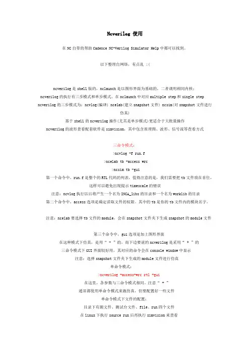
Ncverilog 使用在NC自带的帮助Cadence NC-Verilog Simulator Help中都可以找到。
以下整理自网络,有点乱 :(ncverilog是shell版的,nclaunch是以图形界面为基础的,二者调用相同内核;ncverilog的执行有三步模式和单步模式,在nclaunch中对应multiple step和single step ncverilog的三步模式为:ncvlog(编译) ncelab(建立snapshot文件) ncsim(对snapshot文件进行仿真)基于shell的ncverilog操作(尤其是单步模式)更适合于大批量操作ncverilog的波形查看配套软件是simvision,其中包含原理图、波形、信号流等查看方式三命令模式:>ncvlog -f run.f>ncelab tb -access wrc>ncsim tb -gui第一个命令中,run.f是整个的RTL代码的列表,值得注意的是,我们需要把tb文件放在首位,这样可以避免出现提示timescale的错误注意:ncvlog执行以后将产生一个名为INCA_libs的目录和一个名为worklib的目录第二个命令中,access选项是确定读取文件的权限。
其中的tb是你的tb文件内的模块名字。
注意:ncelab要选择tb文件的module,会在snapshot文件夹下生成snapshot的module文件第三个命令中,gui选项是加上图形界面在这种模式下仿真,是用“ - ”的。
而下边要说的ncverilog是采用“ +”的三命令模式下GUI界面较好用,其对应的命令会在console window中显示注意:选择snapshot文件夹下生成的module文件进行仿真单命令模式:>ncverilog +access+wrc rtl +gui在这里,各参数与三命令模式相同。
注意“ + ”通常都使用单命令模式来跑仿真,但要配置好一些文件单命令模式下文件的配置:目录下有源文件、测试台文件、file、run四个文件在linux下执行source run后再执行simvision来查看run文件内容: ncverilog +access+rw -f filefile文件内容: cnt_tb.v(注意把tb文件放在前)cnt.vtb文件中应该包含:initialbegin$shm_open("wave.shm"); //打开波形保存文件wave.shm$shm_probe(cnt_tb,"AS"); //设置探针endA -- signals of the specific scope 为当前层信号设置探针S -- Ports of the specified scope and below, excluding library cellsC -- Ports of the specified scope and below, including library cellsAS -- Signals of the specified scope and below, excluding library cells 为当前层以以下层信号都设置探针,这是最常用的设置方法AC -- Signals of the specified scope and below, including library cells还有一个 M ,表示当前scope的memories, 可以跟上面的结合使用, "AM" "AMS" "AMC"什么都不加表示当前scope的ports;$shm_close //关闭数据库查看结果时可以在source schemic wave register四个窗口同时查看保存波形信号的方法:1.SHM数据库可以记录在设计仿真过程中信号的变化. 它只在probes有效的时间内记录你setprobe on的信号的变化.2.VCD数据库也可以记录在设计仿真过程中信号的变化. 它只记录你选择的信号的变化.$dumpfile("filename"); //打开数据库$dumpvars; //depth = all scope = all$dumpvars(0); //depth = all scope = current$dumpvars(1, top.u1); //depth = 1 scope = top.u1$dumpoff //暂停记录数据改变,信号变化不写入库文件中$dumpon //重新恢复记录3.Debussy fsdb数据库也可以记录信号的变化,它的优势是可以跟debussy结合,方便调试.如果要在ncverilog仿真时,记录信号, 首先要设置debussy:a. setenv LD_LIBRARY_PATH :$LD_LIBRARY_PATH(path for debpli.so file(/share/PLI/nc_xl//nc_loadpli1))b. while invoking ncverilog use the +ncloadpli1 option. ncverilog -f run.f +debug+ncloadpli1=debpli:deb_PLIPtrfsdb数据库文件的记录方法,是使用$fsdbDumpfile和$fsdbDumpvars系统函数,使用方法参见VCD注意: 在用ncverilog的时候,为了正确地记录波形,要使用参数: "+access+rw", 否则没有读写权限产生FSDB波形文件的若干技巧:/bbs/viewthread.php?tid=2539&;extra=page%3D1下载:/bbs/viewthread.php?tid=3357&;extra=page%3D1ncverilog编译的顺序: ncverilog file1 file2 ....有时候这些文件存在依存关系,如在file2中要用到在file1中定义的变量,这时候就要注意其编译的顺序是从后到前,就先编译file2然后才是file2.,信号的强制赋值force:首先, force语句只能在过程语句中出现,即要在initial 或者 always 中间. 去除force 用release 语句.;initial begin force sig1 = 1'b1; ... ; release sig1; end, force可以对wire赋值,这时整个net都被赋值; 也可以对reg赋值.Verilog和Ncverilog命令使用库文件或库目录ex). ncverilog -f run.f -v lib/lib.v -y lib2 +libext+.v //一般编译文件在run.f中, 库文件在lib.v中,lib2目录中的.v文件系统自动搜索,使用库文件或库目录,只编译需要的模块而不必全部编译Q:我的files里面只有一个help文件夹,里面是一个叫ncprotect文件,没有你所说的hdl.var文件啊A:1、NC-VERILOG在创建工程时会生成两个文件:cds.lib和hdl.var。
modelsim工程后缀Modelsim是一种常用的硬件描述语言仿真软件,它可以模拟数字电路制作的过程。
在使用Modelsim进行工程制作时,为了便于管理和使用,每个工程都会有一个特定的后缀名。
那么,这些工程后缀名有哪些呢?首先,我们需要知道,在使用Modelsim时,一个设计文件会有多个文件组成,包括vhdl文件、verilog文件、testbench文件以及某些外部库文件等。
这些文件需要被综合和仿真,才能进行后面的设计工作。
因此,我们需要对这些文件进行整合,并将它们存储在一个文件夹中,我们称之为Modelsim工程。
Modelsim的工程后缀比较多,根据不同的功能和版本,可能会有所不同。
在Modelsim中,常用的工程后缀名包括:1. .mpf:这是Modelsim 6.0及以下版本所支持的工程后缀名,它是一种简单的工程格式,可以保存整个工程的信息。
2. .msim:这是Modelsim 6.1及以上版本所支持的工程后缀名。
与.mpf相比,它所包含的信息更加详细,能够保存整个工程的设计和仿真流程,更加方便工程管理。
3. .do :这是Modelsim的脚本文件,也是一种工程后缀名,它可以将常用的命令保存在一个文本文件中,方便用户进行快速调用。
在.do文件中可以定义仿真参数、lib库路径、编译选项等。
这种工程后缀名同时也可以用来控制仿真输出结果的显示,化繁为简,提高仿真效率。
4. .ini:这是Modelsim的引导文件,它定义了Modelsim的工作环境、显示格式和仿真选项等。
在工程中使用.ini后缀名,则为一个工程定义了一个特定的工作环境,使工程能够保存自己的仿真选项。
通过上述介绍我们可以看到,针对不同的应用场合和版本,Modelsim工程后缀名的应用也不尽相同。
选择适合自己应用场合的工程后缀名,是Modelsim工程设计的重要一步。
篇一:modelsim仿真小结modelsim仿真小结modelsim的基本仿真流程大致分以下几个步骤:建库、编译工程、前后仿真、调试等。
modelsim 仿真既可以在modelsim界面操作,也可以用do文件实现,这里结合学习的教程、网上看到的资料,和实际遇到的一些问题,分别做一整理小结。
1. 建库建库包括altera 库和xilinx库,同时都包括verilog和vhdl。
这里只建了verilog库,vhdl和verilog步骤相同。
对于altera库主要包括lpm元件库、mega_function库atera_mf、altera原语库altera_primitive和各器件系列模型库。
前三种是调用altera模块的必备库,第四种是进行综合后功能仿真和布线后时序仿真需要的库,和器件系列有关,只选对应系列即可。
altera库创建和编译步骤如下:a) 在modelsim安装目录下新建文件夹,命名altera_lib,以存放编译后的库文件,可以在altera_lib 下新建verilog和vhdl两个子文件夹,分别存放verilog和vhdl库。
b) 打开modelsim,新建library,file ->new->library ..c) 如下图,创建lpm库,路径e:\modeltech_10.1a\altera_lib\verilog\lpm到此,lpm库建立完毕。
e) 同理,建立altera_mf库添加 altera_mf.v ,建立primitive库添加altera_primitive.v建立各系列的模型库,命名可用系列名加_ver“xxx_ver”,也可随意吧,添加各系列的xxx_atoms.v。
这里,也可以把以上库放在一个文件夹,这样做简单,一次就搞定,分开也就是条理清楚,没人去看,所以没必要。
f) 修改modelsim.ini文件,为的是让modelsim能自动map到已经编译的这些库上。

仿真工具ModelSim简介Mentor公司的ModelSim是业界最优秀的HDL语言仿真软件,它能提供友好的仿真环境,是业界唯一的单内核支持VHDL和Verilog混合仿真的仿真器。
它采用直接优化的编译技术、Tcl/Tk技术、和单一内核仿真技术,编译仿真速度快,编译的代码与平台无关,便于保护IP核,个性化的图形界面和用户接口,为用户加快调错提供强有力的手段,是FPGA/ASIC设计的首选仿真软件。
主要特点是:RTL和门级优化,本地编译结构,编译仿真速度快,跨平台跨版本仿真;单内核VHDL和Verilog混合仿真;源代码模版和助手,项目管理;集成了性能分析、波形比较、代码覆盖、数据流ChaseX、Signal Spy、虚拟对象Virtual Object、Memory窗口、Assertion窗口、源码窗口显示信号值、信号条件断点等众多调试功能;C和Tcl/Tk接口,C调试;对SystemC的直接支持,和HDL任意混合;支持SystemVerilog的设计功能;对系统级描述语言的最全面支持,SystemVerilog,SystemC,PSL;ASIC Sign off。
可以单独或同时进行行为(behavioral)、RTL级、和门级(gate-level)的代码。
严格来讲,FPGA设计验证包括功能仿真、时序仿真和电路验证,它们分别对应整个开发流程的每一个步骤。
仿真是指使用设计软件包对已实现的设计进行完整的测试,并模拟实际物理环境下的工作情况。
功能仿真是指仅对逻辑功能进行模拟测试,以了解其实现的功能是否满足原设计的要求,仿真过程没有加入时序信息,不涉及具体器件的硬件特性,如延时特性等,因此又叫前仿真,它是对HDL硬件描述语言的功能实现情况进行仿真,以确保HDL语言描述能够满足设计者的最初意图。
时序仿真则是在HDL可以满足设计者功能要求的基础上,在布局布线后,提取有关的器件延迟、连线延时等时序参数信息,并在此基础上进行的仿真,也成为后仿真,它是接近于器件真实运行状态的一种仿真。
Modelsim 仿真方法总结Modeling 仿真工具是Model公司开发的。
它支持Verilog、VHDL以及他们的混合仿真.Modelsim各版本的使用方法大体一致,Modelsim仿真主要分为前仿真和后仿真。
下面来具体介绍modelsim的仿真方法,涉及quartus—modelsim联合(使用)仿真的差异会特别提示。
前仿真与后仿真说明1。
1 前仿真前仿真也称为功能仿真、行为仿真.旨在验证电路的功能是否符合设计要求,其特点是不考虑延迟(包括门延迟与线延迟),主要验证电路与理想情况是否一致。
前仿真需要用到RTL级代码(由源代码经过综合后产生)与Testbench。
1。
2)后仿真后仿真也称为时序仿真或者布局布线仿真。
是指在电路已经映射到特定的工艺环境以后,综合考虑门延迟与线延迟的影响,验证电路在一定的时序条件下是否存在时序违规以及能否满足设计构想的过程。
需要用到的文件是——从布局布线结果中抽象出来的门级网表、testbench和后缀名为sdo或者sdf的标准时延文件。
注:扩展名为sdo和sdf的标准时延文件包含门延迟与实际布线延迟,能较好的反应芯片的实际工作情况。
二)modelsim仿真主要有以下几个步骤:(1)建立库并映射库到物理目录;(2)编译源代码(包括Testbench);(3)执行仿真;解释:①库:modelsim中有两类仿真库.一种是工作库,默认名为work;另一种是资源库。
Work库中存放当前工程下所有已经编译过的文件,所以编译前一定要建立一个work 库.资源库存放work库中已经编译文件所要调用的资源,这样的资源可能有很多,它们被存放在不同的资源库内。
(例如要想对综合在cyclone芯片中的设计做后仿真,就需要有一个名为cyclone_ver的资源库.)映射库用于将已经预编译好的文件所在目录映射为一个modelsim可识别的库。
(此即是为仿真库建立一个逻辑映像的行为过程,后面会提到,在modelsim中新建库时,create a new library and a logical mapping to it或a map to an existing libraryd的提示) 上述三个步骤是大的框架,前仿真和后仿真均是按照这个框架进行的,建立modelsim工程对前后仿真来说都不是必须的.下面分别介绍每一步的操作。
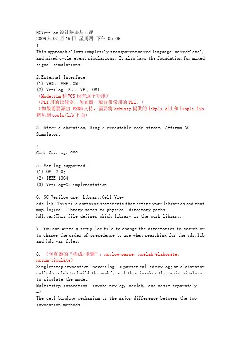
NCVerilog设计秘诀与点评2009年07月16日星期四下午 05:061.This approach allows completely transparent mixed language, mixed-level, and mixed cycle-event simulations. It also lays the foundation for mixed signal simulations.2.External Interface:(1) VHDL: VHPI,OMI(2) Verilog: PLI, VPI, OMI(Modelsim和VCS也有这个功能)(PLI用的比较多,仿真器一般自带常用的PLI。
)(如果需要添加 FSDB支持,需要将debussy提供的libpli.dll和libpli.lib 拷贝到tools/lib下面)3. After elaboration, Single executable code stream, Affirma NC Simulator;4.Code Coverage5. Verilog supported:(1) OVI 2.0;(2) IEEE 1364;(3) Verilog-XL implementation;6. NC-Verilog use: Library.Cell:Viewcds.lib: This file contains statements that define your libraries and that map logical library names to physical directory paths.hdl.var:This file defines which library is the work library.7. You can write a setup.loc file to change the directories to search or to change the order of precedence to use when searching for the cds.lib and hdl.var files.8. (仿真器的“构成-步骤”:ncvlog-parse,ncelab-elaborate,ncsim-simulate)Single-step invocation: ncverilog : a parser called ncvlog; an elaborator called ncelab to build the model, and then invokes the ncsim simulator to simulate the model.Multi-step invocation: invoke ncvlog, ncelab, and ncsim separately. =>The cell binding mechanism is the major difference between the two invocation methods.9.ncpack:change the properties of a database to make it read-only or add-only.inca.architecture.lib_version.pakinca.sun4v.091.pakncls utility: list the objects contained in the library system,10. Library files protect:(1) file locking mechanism: ncpack -unlock, to unlock a file(2) signal handling mechanism ensures that any unexpected event,11. cdsdoc:To invoke the Cadence documentation windowtool_name -helpnchelp [options] tool_name message_code *******ncsim> help [help_options] [command | all [command_options]]11.NCLaunch is a graphical user interfacenclaunchSimVision Waveform Viewer,12.Many of these options have a corresponding plus option that youcan use on the ncverilog command.ncvlog -ieee1364 => ncverilog +ncieee1364When you run ncverilog, the parser is invoked with the -update option by default.13. ncverilog:(1) +debug. This option turns on read access to all objects in the design.=> ncelab -access +r(2) +ncaccess+. Use this option to selectively turn on different kinds of access.e.x.: +ncaccess+r, +ncaccess+r+w(3) +ncafile+access_file: to specify an access file,Three access:Enabling Read, Write, or Connectivity Access to Simulation Objects.14.ncsim -licqueue: license queue(当license不足的时候,用这个语句可以确保有人退出的时候,你能及时获得license)The NC-Verilog simulator command language is based on Tcl.TCL input file: +ncinput+filename or +tcl+filename;15.ncverilog.args in the snap.nc directory: command-line options of ncverilog(所以前一次的命令在彼处有保存)cds.lib and hdl.var file in the INCA_libs directory.All tools share a common log file named ncverilog.log.(查看log文件从而掌握运行时情况是最重要的debug方法之一)Design units in files specified directly on the command line are compiled into the work library, and design units specified in -y libraries or -v library files are compiled into libraries that have the same names.Writes the SNAPSHOT variable to the hdl.var file in the snap.nc directory to store the name of the snapshot used in this run.---The SNAPSHOT variable in the hdl.var file is used to determine what snapshot wascreated the last time this directory was used.16. The next time you invoke ncverilog, it compares the current set of command-line options to the options stored in the ncverilog.args file. All of the plus options and dash options must be the same and in the same order for the options to be evaluated as equal.17.The ncverilog +ncuid+ncuid_name option enables functionality in ncverilog that lets you run multiple simulations using the same intermediate objects and the same storage locations. The +ncuid+ option enables this functionality by providing a unique ID name for each simulation.18. (命令行参数含义)ncverilog -h +all+cdslib+path+checkargs: Display a list of the arguments used on the command line. +compile: Run ncvlog to compile the design, but do not invoke ncelab toelaborate the design or ncsim to simulate.+debug:Turn on read access to all objects in the design.This option is the same as +ncaccess+r.+elaborate:Run ncvlog and ncelab+expand: Expand all vectors.+hdlvar+path-h+import:Prepare this Verilog design for import to VHDL.+mixedlang:Search the library structure for a VHDL binding for instances that correspond to VHDL import.+name+name: Use the specified name for the snapshot and for theINCA_libs/snap.nc directory.+ncelabargs+string:Pass the specified ncelab command options to the elaborator before invoking it.+ncelabexe+path_to_ncelab+ncerror+warning_code:Increase the severity level of the specified warning message from warning to error.+ncfatal+{warning_code | error_code}: Increase the severity level of the specified warning message or error message from warning or error to fatal. +nclibdirname+directory_name: to change INCA_libs+ncls_all:List all of the objects in all libraries.+ncls_dependents:Show the dependents for each object.+ncls_snapshots: List all snapshot (SSS) objects.+ncls_source:Show the source file dependents of each object.+ncsimargs+string+ncsimexe+path_to_ncsim+ncuid+ncuid_name+ncvlogargs+string+noautosdf:Do not perform automatic SDF annotation.+noupdate: prevents the writing of intermediate objects for design units that are up-to-date.+ppe:Invoke the Post Processing Environment (PPE).-R: Invoke the simulator (ncsim) to simulate the snapshot in theINCA_libs/worklib directory.-r snapshot: Load the specified snapshot.+sdf_orig_dir:Put the compiled SDF file in same location as the original SDF file.+work+library_name:Use the specified library as the work library.-c Compile and elaborate only. //same to Verilog-XL20.ncverilog:+tcl+filename,+ncinput+filename:The NC-Verilog simulator command language is based on Tcl.21.The compiled SDF file:dcache.sdf.test1.X).Snapshots are always named lib.cell:ncuid_name22. $test$plusargs% ncverilog -R +userarg% ncverilog -R +some_other_userarg23. // To understand the concept of Snapshot% ncverilog source.v +ncuid+test1% ncverilog source.v +ncuid+test2Two snapshots are generated in the INCA_libs/worklib directory: worklib.top:test1 and worklib.top:test2.you generate two snapshots using the following command lines:% ncverilog source.v +elaborate% ncverilog source.v +elaborate +ncaccess+r +nclibdirname+MYINCA_libs +name+debug=> To simulate this snapshot:% ncverilog -R +nclibdirname+MYINCA_libs +name+debug[+simulator_options]ing -r to Simulate a Saved Snapshot:% ncverilog -f verilog.vc +elaborate% ncverilog -R -sncsim> run 1000ncsim> save save1ncsim> exit//To simulate the saved snapshot, specify the snapshot name with the -r option,% ncverilog -r worklib.save1:v // or: ncverilog -r save1=> Simulation Environment:If you want to restore the full Tcl debug environment when you restart with a saved snapshot, make sure that you save the environment with the save -environment filename command. This command creates a Tcl script that captures the current breakpoints, databases, probes, aliases, and predefined Tcl variable values. You can then use the +ncinput+ option when you invoke ncverilog to execute the script, or you can invoke ncverilog in interactive mode with the -s option and then use the Tcl source command to source the script.ncsim> save -environment ckpt1.tclncverilog -s -r worklib.top:ckpt1 +ncinput+ckpt1.tclNote: If you set a breakpoint that triggers, for example, every 10 ns (that is, at time 10, 20, 30, and so on) and restart with a snapshot saved at time 15, the breakpoint triggers at 20, 30, and so on, not at time 25, 35, and so on.25.-R: The -R option lets you simulate the same snapshot multiple times using different simulatorcommand-line options.-r: You can use the -r option to load a snapshot.26.SDF versions 1.0, 2.0, 2.1, and 3.0. For versions 2.0 and above, use the SDFVERSION statement in the header of the SDF file to specify the version.SDF annotation is performed during elaboration. The elaborator recognizes $sdf_annotate system tasks in the design source files,to override the default automatic SDF annotation mechanism and force annotation by using the +sdf_cmd_file+filename optionSDF: The NC-Verilog simulator reads only compiled SDF files.(1) text SDF file, cpu.sdf,(2) compiled file: cpu.sdf.X.ncsdfc utility to automatically compile the SDF file.Using $test$plusargs to Selectively Perform Annotations:if ($test$plusargs( preroute ))$sdf_annotate( preroute.sdf , m1);else if ($test$plusargs( postroute ))$sdf_annotate( postroute.sdf , m1);The ncsdfc utility always compiles the SDF file with a precision of 1 fs. The elaborator annotates each module using the precision of the module or the precision set by using the ncelab -sdf_precision command_line option.30.Turning Off SDF Annotation:(1) Use the +noautosdf option on the ncverilog command line.(2) Comment out the $sdf_annotate system task(s) in the Verilog source file.31.+sdf_cmd_file+filename32.You can use the -ieee1364 command-line option when you compile the design with ncvlog and elaborate the design with ncelab to check your code for compatibility with the IEEE standard.33. IEEE 1364 - 1995 Verilog: array of instances, bufif0 ar[3:0] (out, in, en); // array of tri-state buffers However, an array of instances must have a continuous range.34. Set up your environment:cds.libhdl.varsetup.loc35.Verilog: module, macromodule, or UDPVHDL: entity, architecture, package, package body, or configuration36.internal intermediate objects:library database file (.pak file)37.cds.lib:DEFINE worklib ../worklibDEFINE lib_std /usr1/libs/std_libYou can have more than one cds.lib file.Use the INCLUDE or SOFTINCLUDE statements to include a cds.lib file within a cds.lib If you are doing a pure VHDL or a mixed-language simulation, you must use the INCLUDE or SOFTINCLUDE statement in the cds.lib (System provide one)SOFTINCLUDE is the same as the INCLUDE statement, except that no error messages are printed if the file does not exist.38. Binding One Library to Multiple Directories:DEFINE iclib ./ic_libASSIGN iclib TMP ./ic_tmp_lib...UNASSIGN iclib TMP38. -- can be used to check the content of the cds.lib% nchelp -cdslib39. hdl.libDEFINE WORK worklibDEFINE VERILOG_SUFFIX (.v, .vg, .vb)NCVLOGOPTS -messages -errormax 10 -update40. hdl.var% nchelp -hdlvar41. view & snapshot(1) The file mychip.v gets compiled into the default moduleview:worklib.mychip:module.It is created after compile, (ncvlog)(2) The elaborator generates a simulation snapshot for the design. Intermediate objects created during the elaboration phase are stored in the .pak file.The snapshot is also a Lib.Cell:View.source =>(compile)=> module =>(elaborate) => snapshot => simulation, So the snapshot is the object of simulator。
modelsim 仿真语法摘要:一、modelsim 简介二、modelsim 仿真语法1.基本架构2.触发条件控制符3.常用仿真控制语句4.文本输入正文:一、modelsim 简介modelsim 是一种用于验证和仿真数字电路的软件工具,可以帮助设计人员在开发过程中检测和修复潜在的问题。
通过modelsim,设计人员可以在计算机上模拟数字电路的行为,观察其响应,并进行必要的调整。
modelsim 具有强大的功能,可以支持多种数字电路设计语言,如Verilog 和VHDL 等。
二、modelsim 仿真语法1.基本架构modelsim 仿真文件的基本架构包括以下几个部分:- 库(library):存储仿真模型的文件,包括模块、行为描述和测试平台等。
- 模块(module):存储实际的电路设计,包括输入端口、输出端口和逻辑实现等。
- 行为描述(behavioral description):描述模块的功能和行为,通常使用Verilog 或VHDL 语言编写。
- 测试平台(test platform):编写测试用例和观察结果的地方,用于验证模块的正确性。
2.触发条件控制符在modelsim 中,可以使用触发条件控制符来控制仿真过程。
常用的触发条件控制符包括:- @:表示仿真过程中的某个时刻或事件。
- wait:表示仿真过程中的等待,用于暂停仿真过程,直到指定的事件发生。
3.常用仿真控制语句在modelsim 中,可以使用一些系统函数来控制仿真过程,如:- $display:用于显示仿真过程中的信息和消息。
- $monitor:用于观察仿真过程中的某个信号或变量。
- $stop:用于终止仿真过程。
4.文本输入在modelsim 中,可以通过文本输入的方式来编写仿真测试用例。
文本输入可以包括以下几个部分:- 输入信号:描述输入信号的类型、名称和初始值。
- 输入延迟:描述输入信号的延迟时间。
- 测试用例:编写实际的测试用例,包括输入信号的值和期望的输出结果。
[数字芯⽚]SystemVerilog与Modelsim⾃动化仿真简单Verilog编写数字电路的各个模块,必须伴随着⼀testbench⽂件⽤作仿真验证。
简单的module当然可以使⽤简单的Verilog编写⼀个testbench进⾏简单的仿真,但⼀旦遇到功能较为复杂时,Verilog语⾔的灵活性不⾜C/C++这类语⾔。
SystemVerilog作为⼀门针对验证的⾯向对象的编程语⾔,能够更好的描述时序,同时具有⾯向对象语⾔的灵活性以及重复使⽤性,能够为⼯程仿真带来许多便利。
接下来,简单使⽤SystemVerilog对序列检测的module进⾏仿真验证。
⼀、⼯程框架本⼯程测试⼀个使⽤状态机检测“1110010”序列的module,包含五个⽂件,具体描述如下:├── top.sv:顶层模块,⽤以连接下列各个模块││├── module_bfm.sv: 模块的bus functional model,描述⽤以连接的interface││├── tester.sv: 产⽣仿真的时序信号││├── coverage.sv: 对模块覆盖率的检测││├── module.v: 待仿真验证的模块由于module是使⽤Verilog编写的,不能直接使⽤Interface, ⽽需要按照Verilog的规范进⾏连接,⽽其余SV的module直接使⽤BFM连接。
module top();seq_fsm_bfm bfm();coverage converage_i(bfm);tester tester_i(bfm);seq_fsm seq_fsm_i(.in(bfm.in),.out(bfm.out),.state(bfm.state),.clk(bfm.clk),.reset(bfm.rst_n));endmodule⼆、SystemVerilog的interface使⽤使⽤Verilog是对于module端⼝的连接,不管使⽤顺序还是使⽤名称连接都容易出错以及极为繁琐。
Modelsim 仿真软件的学习及理解一、软件简介Modelsim仿真工具支持Verilog、VHDL以及他们的混合仿真,它可以将整个程序分步执行,使设计者直接看到他的程序下一步要执行的语句,而且在程序执行的任何步骤任何时刻都可以查看任意变量的当前值,可以在Dataflow窗口查看某一单元或模块的输入输出的连续变化,具备强大的模拟仿真功能,在设计、编译、仿真、测试、调试开发过程中,有一整套工具供你使用,而且操作起来极其灵活,可以通过菜单、快捷键和命令行的方式进行工作。
ModelSim的窗口管理界面让用户使用起来很方面,它能很好的与操作系统环境协调工作。
ModelSim的一个很显著的特点就是它具备命令行的操作方式。
modelsim是业界唯一的单内核支持VHDL和Verilog混合仿真的仿真器;具有源代码模版和助手,项目管理等特点。
Mentor公司的ModelSim是业界最优秀的HDL语言仿真软件,它能提供友好的仿真环境,是业界唯一的单内核支持VHDL和Verilog混合仿真的仿真器。
它采用直接优化的编译技术、Tcl/Tk技术、和单一内核仿真技术,编译仿真速度快,编译的代码与平台无关,便于保护IP核,个性化的图形界面和用户接口,为用户加快调错提供强有力的手段,是FPGA/ASIC设计的首选仿真软件。
RTL和门级优化,本地编译结构,编译仿真速度快,跨平台跨版本仿真;单内核VHDL和Verilog混合仿真;源代码模版和助手,项目管理;集成了性能分析、波形比较、代码覆盖、数据流ChaseX、Signal Spy、虚拟对象Virtual Object、Memory窗口、Assertion窗口、源码窗口显示信号值、信号条件断点等众多调试功能; C和Tcl/Tk接口,C调试;对SystemC的直接支持,和HDL任意混合;支持SystemVerilog的设计功能;对系统级描述语言的最全面支持,SystemVerilog,SystemC,PSL;ASIC Sign off。
ModelSim仿真⼊门ModelSim仿真⼊门之⼀:软件介绍编写这个教程之前,为了让不同⽔平阶段的⼈都能阅读,我尽量做到了零基础⼊门这个⽬标,所有的操作步骤都经过缜密的思考,做到了详细再详细的程度。
如果您是FPGA开发⽅⾯的初学者,那么这个教程⼀定能够帮助你在仿真技术上越过新⼈的台阶;如果您是FPGA开发的⽼⼿,这篇⽂档也并⾮对您没有帮助,您可以把教程发给其他刚⼊门的同事,免去您亲⾃上阵指导的⿇烦,把主要的精⼒放在更有价值的地⽅。
⼀、FPGA设计仿真验证简介严格来讲,FPGA设计验证包括功能仿真、时序仿真和电路验证,它们分别对应整个开发流程的每⼀个步骤。
仿真是指使⽤设计软件包对已实现的设计进⾏完整的测试,并模拟实际物理环境下的⼯作情况。
功能仿真是指仅对逻辑功能进⾏模拟测试,以了解其实现的功能是否满⾜原设计的要求,仿真过程没有加⼊时序信息,不涉及具体器件的硬件特性,如延时特性等,因此⼜叫前仿真,它是对HDL硬件描述语⾔的功能实现情况进⾏仿真,以确保HDL语⾔描述能够满⾜设计者的最初意图。
时序仿真则是在HDL可以满⾜设计者功能要求的基础上,在布局布线后,提取有关的器件延迟、连线延时等时序参数信息,并在此基础上进⾏的仿真,也成为后仿真,它是接近于器件真实运⾏状态的⼀种仿真。
⼆、仿真软件ModelSim及其应⽤HDL的仿真软件有很多种,如VCS、VSS、NC-Verilog、NC-VHDL、ModelSim等,对于开发FPGA来说,⼀般是使⽤FPGA⼚家提供的集成开发环境,他们都有⾃⼰的仿真器,如Xilinx公司的ISE,Altera公司的Quartus II等,但是这些⼚家开发的仿真器的仿真功能往往⽐不上专业的EDA公司的仿真⼯具,如ModelSim AE(Altera Edition)、ModelSim XE(Xilinx Edition)等。
Quartus II设有第三⽅仿真⼯具的接⼝,可以直接调⽤其他EDA公司的仿真⼯具,这极⼤地提⾼了EDA设计的⽔平和质量。
Modelsim和NCverilog的比较
集成电路的发展趋势是,单位面积集成的晶体管的数目越来越多,可靠性越来越越高、稳定性越来越好。
现在芯片集成度已经超出可人们的想象,有的芯片内部集成了数百万的晶体管,已经远远超出了人的大脑可以分析的范围。
这就对EDA工具提出了更高的要求,不管是设计、仿真、综合软件的发展,都给集成电路工程师带来了巨大的便利。
modelsim是Mentor graphics公司推出的HDL代码仿真工具,也是业界最流行的HDL仿真工具之一。
支持图形界面操作和脚本操作,常见的图形界面操作相对直观,但是由于重复性操作几率高、处理效率低、工程的非保存性,对于大规模的代码仿真不推荐使用;脚本操作完全可以克服以上的缺点,把常见的命令,比如库文件和RTL加载、仿真、波形显示等命令编辑成.do脚本文件,只需要让Modelsim运行.do文件即可以完成仿真,智能化程度高。
NCverilog是candence公司推出的Verilog HDL的仿真工具。
NC-Verilog是Verilog-XL的升级版, 它采用Native-Compiled技术, 无论仿真速度, 处理庞大设计能力, 编辑能力, 记忆体容量和侦错环境都以倍数升级。
C-Verilog是一个编译仿真器,它把Verilog代码编译成Verilog程序的定制仿真器。
也就是它把Verilog 代码转换成一个C程序,然后再把该C程序编译成仿真器。
因此它启动得稍微慢一些,但这样生成的编译仿真器运行得要比Verilog-XL的解释仿真器快很多。
Ncverilog是shell版的,nclaunch是以图形界面为基础的,二者调用相同内核;Ncverilog的执行有三步模式和单步模式,在nclaunch中对应multiple step和single step;Ncverilog的三步模式为:ncvlog(编译) ncelab(建立snapshot文件) ncsim(对snapshot文件进行仿真)基于shell的ncverilog操作(尤其是单步模式)更适合于大批量操作,hncverilog的波形查看配套软件是simvision,其中包含原理图、波形、信号流等查看方式。
Ncverilog命令使用库文件或库目录
ex). ncverilog -f run.f -v lib/lib.v -y lib2 +libext+.v //一般编译文件在run.f 中, 库文件在lib.v中,lib2目录中的.v文件系统自动搜索使用库文件或库目录,只编译需要的模块而不必全部编译。
Verilog Testbench信号记录的系统任务:
1). SHM数据库可以记录在设计仿真过程中信号的变化. 它只在probes有效的时间内记录你set probe on的信号的变化。
ex). $shm_open("waves.shm"); //打开波形数据库
$shm_probe(top, "AS"); // set probe on "top"
第二个参数: A -- signals of the specific scrope
S -- Ports of the specified scope and below, excluding library cells;
C -- Ports of the specified scope and below, including library cells;
AS -- Signals of the specified scope and below, excluding library cells;
AC -- Signals of the specified scope and below, including library cells。
还有一个M ,表示当前scope的memories, 可以跟上面的结合使用, "AM" "AMS" "AMC"什么都不加表示当前scope的ports;$shm_close //关闭数据库
2). VCD数据库也可以记录在设计仿真过程中信号的变化. 它只记录你选择的信号的变化。
ex). $dumpfile("filename"); //打开数据库
$dumpvars(1, top.u1); //scope = top.u1, depth = 1
第一个参数表示深度, 为0时记录所有深度; 第二个参数表示scope,省略时表当前的scope。
$dumpvars; //depth = all scope = all
$dumpvars(0); //depth = all scope = current
$dumpvars(1, top.u1); //depth = 1 scope = top.u1
$dumpoff //暂停记录数据改变,信号变化不写入库文件中
$dumpon //重新恢复记录
3). Debussy fsdb数据库也可以记录信号的变化,它的优势是可以跟debussy结合,方便调试。
如果要在ncverilog仿真时,记录信号, 首先要设置debussy:
a. setenv LD_LIBRARY_PATH :$LD_LIBRARY_PATH(path for debpli.so file (/share/PLI/nc_xl//nc_loadpli1));
b. while invoking ncverilog use the +ncloadpli1 option.ncverilog -f run.f +debug +ncloadpli1=debpli:deb_PLIPtr;
fsdb数据库文件的记录方法,是使用$fsdbDumpfile和$fsdbDumpvars系统函数。
注意: 在用ncverilog的时候,为了正确地记录波形,要使用参数: "+access+rw", 否则没有读写权限。
ncverilog编译的顺序: ncverilog file2 file1 ....
有时候这些文件存在依存关系,如在file2中要用到在file1中定义的变量,这时候就要注意其编译的顺序是从后到前,就先编译file2然后才是file1。
信号的强制赋值force
首先, force语句只能在过程语句中出现,即要在initial 或者always 中间,去除force 用release 语句。
initial begin force sig1 = 1'b1; ... ; release sig1; end;
force可以对wire赋值,这时整个net都被赋值,也可以对reg赋值。
Modelsim的仿真命令和库文件
Modelsim的仿真界面非常的便利,设计者可以根据modelsim自己的程序设计流程,来设置自己的仿真需要,可以来说是很容易使用的。
但是在编译和仿真的大的程序时,所需的时间相对来说比较长。
Modelsim还支持数据流的追踪模式,是一个入门学习Verilog的不错的软件。
设计流程是,首先建立一个物理库(modelsim库),之后建立工程文件,之后向工程中添加我们自己所需的工程子文件,之后运行编译系统,编译通过后可以运行仿真器。
在运行仿真器时,可以指定时间的精度和仿真时间的长度。
等到仿真结束之后我们可以查看输入输出信号的波形。
这只是modelsim的最基本的功能,其中modelsim还可以波形追踪和代码覆盖等高级的功能。