Cadence 实验系列10_Verilog设计平台_NC-Verilog
- 格式:ppt
- 大小:4.49 MB
- 文档页数:78
NC-Verilog仿真技巧提高NC-Verilog仿真效率的技巧本文回顾了一些NC-Verilog的命令行选项,并说明这些选项如何影响仿真效率。
同时,我们也展示了一些技巧,以帮助用户的NC-Verilog在最大效率下仿真一个设计和测试平台。
文中的命令行选项语法采用单步启动的方式(ncverilog +),这些选项也适合多步启动模式(ncvlog, ncelab, 或ncsim)。
安装最新发布的软件首先确认你是否安装了最新的Cadence LDV版本。
自动1996年发布第一版NC-Verilog以来,我们的研发队伍一直把仿真器的仿真效率作为重点来研究。
在后来推出的新版本里,不断按各种设计风格优化仿真器,因此使用最新版本是最有利的。
直到2002年2月,最新版本是LDV 3.4(s1)。
使用NC-Verilog内置的profilerNC-Verilog在仿真引擎内开发了一个profiler工具。
该工具每秒中断仿真器100次,并将终端时的结构记录下来,生成一个日志文件。
日志文件里列出了被中断次数最多的模块、代码行和结构类型。
这些信息可以帮助你诊断是哪些代码或模块在仿真时耗费了最多的时间。
通过修改这些模块,就能提升仿真效率。
Profiler功能很容易启动,并对仿真只产生非常小的影响。
% ncverilog +ncprofileor% ncsim –profile snapshot_name在仿真结束时,profiler会创建一个日志文件(ncprof.out),文件里列出了profile运行的细节。
关于如何利用profiler日志文件,可参考Cadence在线文档(Cadence NC-Verilog Simulator Help, Version 3.4, Chapter 14)。
禁止时序验证来提升效率缺省情况下,如果在设计中考虑了时序,NC-Sim将进行标准延迟格式(SDF)的全时序标注(annotation),并在仿真时检查时序。
Ncverilog 的一些经验1.Verilog和Ncverilog命令使用库文件或库目录ex). ncverilog -f run.f -v lib/lib.v -y lib2 +libext+.v //一般编译文件在run.f中, 库文件在lib.v中,lib2目录中的.v文件系统自动搜索使用库文件或库目录,只编译需要的模块而不必全部编译2.Verilog Testbench信号记录的系统任务:1). SHM数据库可以记录在设计仿真过程中信号的变化. 它只在probes有效的时间内记录你set probe on的信号的变化.ex). $shm_open("waves.shm"); //打开波形数据库$shm_probe(top, "AS"); // set probe on "top",第二个参数: A -- signals of the specific sc ropeS -- Ports of the specified s cope and below, excluding library cellsC -- Ports of the specified s cope and below, including library cellsAS -- Signals of the specifie d scope and below, excluding library cellsAC -- Signals of the specifie d scope and below, including library cells还有一个 M ,表示当前scope的m emories, 可以跟上面的结合使用, "AM" "AMS" "AMC"什么都不加表示当前scope的por ts;$shm_close //关闭数据库2). VCD数据库也可以记录在设计仿真过程中信号的变化. 它只记录你选择的信号的变化.ex). $dumpfile("filename"); //打开数据库$dumpvars(1, top.u1); //scope = top.u1, depth = 1第一个参数表示深度, 为0时记录所有深度; 第二个参数表示scope,省略时表当前的scope.$dumpvars; //depth = all scope = all$dumpvars(0); //depth = all scope = current $dumpvars(1, top.u1); //depth = 1 scope = top. u1$dumpoff //暂停记录数据改变,信号变化不写入库文件中$dumpon //重新恢复记录3). Debussy fsdb数据库也可以记录信号的变化,它的优势是可以跟debus sy结合,方便调试.如果要在ncverilog仿真时,记录信号, 首先要设置debussy:a. setenv LD_LIBRARY_PATH :$LD_LIBRARY_PATH(path for debpli.so file (/share/PLI/nc_xl//nc_loadpli1)) b. while invoking ncverilog use the +ncloadpli1 option.ncverilog -f run.f +debug +ncloadpli1=debpli:deb_PLIPtr fsdb数据库文件的记录方法,是使用$fsdbDumpfile和$fsdbDumpvars系统函数,使用方法参见VCD注意: 在用ncverilog的时候,为了正确地记录波形,要使用参数: "+acces s+rw", 否则没有读写权限3. ncverilog编译的顺序: ncverilog file2 file1 ....有时候这些文件存在依存关系,如在file2中要用到在file1中定义的变量,这时候就要注意其编译的顺序是从后到前,就先编译file2然后才是file1.4. 信号的强制赋值force首先, force语句只能在过程语句中出现,即要在initial 或者 always 中间. 去除force 用 release 语句.initial begin force sig1 = 1'b1; ... ; release sig1; end force可以对wire赋值,这时整个net都被赋值; 也可以对reg赋值.ncverilog使用ncverilog是shell版的,nclaunch是以图形界面为基础的,二者调用相同内核;ncverilog的执行有三步模式和单步模式,在nclaunch中对应multiple step和single stepncverilog的三步模式为:ncvlog(编译) ncelab(建立snapshot文件) ncsim(对snapshot文件进行仿真)基于shell的ncverilog操作(尤其是单步模式)更适合于大批量操作ncverilog的波形查看配套软件是simvision,其中包含原理图、波形、信号流等查看方式三命令模式:ncvlog -f run.fncelab tb -access wrcncsim tb -gui第一个命令中,run.f是整个的RTL代码的列表,值得注意的是,我们需要把tb文件放在首位,这样可以避免出现提示timescale的错误注意:ncvlog执行以后将产生一个名为INCA_libs的目录和一个名为worklib的目录第二个命令中,access选项是确定读取文件的权限。
verilog实验报告Verilog实验报告引言:Verilog是一种硬件描述语言(HDL),用于设计和模拟数字电路。
它是一种高级语言,能够描述电路的行为和结构,方便工程师进行数字电路设计和验证。
本实验报告将介绍我在学习Verilog过程中进行的实验内容和所获得的结果。
实验一:基本门电路设计在这个实验中,我使用Verilog设计了基本的逻辑门电路,包括与门、或门和非门。
通过使用Verilog的模块化设计,我能够轻松地创建和组合这些门电路,以实现更复杂的功能。
我首先创建了一个与门电路的模块,定义了输入和输出端口,并使用逻辑运算符和条件语句实现了与门的功能。
然后,我创建了一个测试模块,用于验证与门的正确性。
通过输入不同的组合,我能够验证与门的输出是否符合预期。
接下来,我按照同样的方法设计了或门和非门电路,并进行了相应的测试。
通过这个实验,我不仅学会了使用Verilog进行基本门电路的设计,还加深了对逻辑电路的理解。
实验二:时序电路设计在这个实验中,我学习了如何使用Verilog设计时序电路,例如寄存器和计数器。
时序电路是一种具有状态和时钟输入的电路,能够根据时钟信号的变化来改变其输出。
我首先设计了一个简单的寄存器模块,使用触发器和组合逻辑电路实现了数据的存储和传输功能。
然后,我创建了一个测试模块,用于验证寄存器的正确性。
通过输入不同的数据和时钟信号,我能够观察到寄存器的输出是否正确。
接下来,我设计了一个计数器模块,使用寄存器和加法电路实现了计数功能。
我还添加了一个复位输入,用于将计数器的值重置为初始状态。
通过测试模块,我能够验证计数器在不同的时钟周期内是否正确地进行计数。
通过这个实验,我不仅学会了使用Verilog设计时序电路,还加深了对触发器、寄存器和计数器的理解。
实验三:组合电路设计在这个实验中,我学习了如何使用Verilog设计组合电路,例如多路选择器和加法器。
组合电路是一种没有状态和时钟输入的电路,其输出只取决于当前的输入。

Ncverilog命令使用详解NCVerilog是一种用于模拟、调试和分析Verilog和SystemVerilog 代码的命令行工具。
以下是对NCVerilog命令使用的详细解释。
1. `ncverilog`命令:启动NCVerilog编译器。
语法如下:```ncverilog [options] <file_list>```- `options`:附加的编译选项,例如`-sv`表示编译SystemVerilog 代码。
- `file_list`:包含要编译的源文件的列表。
2. `+access+r`选项:允许模拟工具读取源代码中的注释。
这对于调试和分析时非常有用。
3. `+define+<macro>`选项:定义一个宏。
这可以用于在模拟期间改变代码的行为。
例如:```+define+DEBUG```4. `+incdir+<dir>`选项:指定包含库文件的目录。
这对于使用外部库或模块时非常有用。
5. `+define+<macro>={value}`选项:为宏指定一个值。
例如:```+define+WIDTH=8```6. `+libext+<ext>`选项:指定库文件的扩展名。
可以用于指定Verilog或SystemVerilog库文件的不同扩展名。
``````8. `+vcs`选项:指定使用VCS编译器的系统Verilog代码。
这对于一些特定的系统Verilog代码可能是必需的。
9. `-y <dir>`选项:指定一个目录,其中包含其他用户定义的Verilog或SystemVerilog库文件。
10. `-v <file>`选项:指定一个要编译的单独的库文件。
11. `-f <file>`选项:指定一个包含文件列表的文件。
这可以用于指定要编译的多个源文件。
12. `-fsmdebug`选项:在编译期间为FSM(有限状态机)创建调试信息。
Ncverilog 命令使用详解我们知道,由于NC-Verilog使用了Native Compile Code 的技术来加强电路模拟的效率,因此在进行模拟时必须经过compile(ncvlog 命令)以及elaborate(n celab命令)的步骤。
编译之后,针对每一个HDL设计单元会产生中间表达。
接着elaborate命令会建立整个电路的结构,产生可以用来模拟的资料。
最后使用ncsim命令来进行模拟。
三命令模式命令如下:ncvlog -f run.fncealb tb -access wrcncsim tb -gui第一个命令中,run.f是整个的RTL代码的列表,值得注意的是,我们需要把tb 文件放在首位,这样可以避免出现提示timescale的错误。
第二个命令中,access选项是确定读取文件的权限。
其中的tb是你的tb文件内的模块名字。
第三个命令中,gui选项是加上图形界面值得注意的是,在这种模式下仿真,是用“ - ”的。
而下边要说的ncverilog是采用“ + ”的。
单命令模式ncverilog +access+wrc rtl +gui在这里,各参数与三命令模式相同。
注意“ + ”。
在本文里将详细讲述ncverilog 的各种常用的参数,对于三命令模式,请读者自己查看资料。
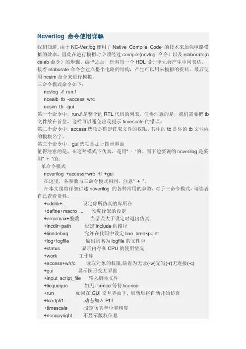
+cdslib+... 设定你所仿真的库所在+define+macro ... 预编译宏的设定+errormax+整数当错误大于设定时退出仿真+incdir+path 设定include的路径+linedebug 允许在代码中设定line breakpoint+log+logfile 输出到名为logfile的文件中+status 显示内存和CPU的使用情况+work 工作库+access+w/r/c 读取对象的权限,缺省为无读(-w)无写(-r)无连接(-c)+gui 显示图形交互界面+input script_file 输入脚本文件+licqueque 如无licence等待licence+run 如果在GUI交互界面下, 启动后将自动开始仿真+loadpli1=... 动态加入PLI+timescale 设定仿真单位和精度+nocopyright 不显示版权信息。
公司概述Cadence是全球电子设计自动化(EDA领先企业,从事软件与硬件设计工具、芯片知识产权与设计服务,目前正致力于EDA产业的转型。
Cadence把此次转型构想命名为EDA360,因为它将包含设计过程中的所有方面,并关注最终产品的可盈利性。
这种应用驱动型方法,能在创建、集成与优化电子设计方面帮助我们的客户以更低的成本和更高的质量完成硅芯片、片上系统设备、以及完整的系统实现。
Cadence Design System, Inc.公司成立于1988年,总部位于美国加州圣荷塞,其设计中心、研发中心和销售部门分布于世界各地。
CADENCE中国1992年Cadence 公司进入中国大陆市场,迄今已拥有大量的集成电路 (IC 及系统设计客户群体。
在过去的二十年里,Cadence公司在中国不断发展壮大,建立了北京、上海、深圳分公司以及北京研发中心、上海研发中心,并于2008年将亚太总部设立在上海,Cadence中国现拥有员工400余人。
北京研发中心和上海研发中心主要承担美国公司总部EDA软件研发任务,力争提供给用户更加完美的设计工具和全流程服务。
Cadence在中国拥有强大的技术支持团队,提供从系统软硬件仿真验证、数字前端和后端及低功耗设计、数模混合RF 前端仿真与DFM以及后端物理验证、SiP封装以及PCB设计等技术支持。
我们的销售方案中还包括提供专业设计服务,VCAD团队为用户提供高质量、有效的设计和外包服务。
把世界顶尖的产品技术和服务融入中国,成为中国电子行业最亲密合作伙伴,和中国电子高科技产业共同腾飞是Cadence 在中国的坚定信念。
市场与趋势Cadence服务于产值达2万亿美元的全球电子市场,其中包括产值超过3000亿美元的半导体市场。
我们的主要垂直市场领域包括:有线与无线通讯;工业、医疗与汽车电子;计算机与消费电子,比如多媒体和个人娱乐设备。
这些领域占全球电子设备营收和半导体营收的90%以上。
Cadence IC设计实验实验六 NC-Verilog Simulator实验实验目的:NC_verilog仿真器的使用,包括编译、运行和仿真。
预备工作:cp /eva01/cdsmgr/ training_IC_data/NCVlog_5_0.tarZ .tar -vxfZ NCVlog_5_0.tarZLab1。
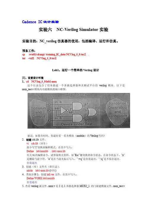
运行一个简单的Verilog设计[1]、设置设计环境1.cd NCVlog_5_0/lab1-mux这个目录包含了用来描述一个多路选择器和其测试平台的verilog 模块。
以下是mux_test.v模块内功能模块的端口框图。
建议:如果有时间,你最好看一看各模块(module)的Verilog代码!2.创建cds.lib文件,vi cds.lib(回车)按小写”i”切换到编辑模式,在其中写入:Define lab1muxlib ./lab1-mux.lib有关vi的编辑命令,请参阅相关资料。
如”Esc”键切换到命令状态,在命令状态下,”x”是删除当前字符,”a”是在当前光标后写入,”:wq”是存盘退出,”:!q”是不保存退出。
存盘退出3.创建(库)文件夹(即目录):mkdir lab1-mux.lib (回车)4.类似步骤1,创建hdl.var文件,在其中写入:Define WORK lab1muxlib存盘退出5.查看verilog源文件。
mux.v是2选1多路选择器MUX2_1 的门级建模源文件,mux_test.v是mux.v的测试台,包含了输入激励信号和监控程序运行的任务语句。
[2]、编译源文件(ncvlog命令):当前目录应为。
/你的学号/NCVlog_5_0/lab1-mux。
1.ncvlog mux.v –messages ,这条指令是编译mux.v。
2.vi hdl.var打开hdl.var文件,在其中添加:Define NCVLOGOPTS –messages 存盘退出注:用NCVLOGOPTS变量定义常用的ncvlog命令行操作,从而避免每次都敲入同样的命令行。
- Cadence中V erilog XL的一些使用方法一、学习Verilog 的必要性。
随着电路规模的增大和复杂,传统的图形输入模式已不可行。
语言描述电路成为潮流。
它的方便性和好的更改性、维护性在实践中得到很好的体现。
尤其现在强大的综合工具,和系统集成对核的需求性使Verilog更有用武之地。
每个硬件工程师应该学习掌握它。
二、Verilog 的文本编辑器。
在进入Cadence后在命令行中键入textedit *.v↙(此处*为文件名,在textedit 命令后应带上文件名)键入上述命令后进入文本编辑框,和Windows 中常用的文本编辑框很象。
图1、textedit文本编辑框界面图中的主菜单File、View、Edit、Find及各自底下的子菜单和Windws中的文本编辑器差不多,使用方法相似,这里就不多说了。
编好程序保存可以进行后续工作了。
三、Verilog 的模拟仿真。
1、命令的选择。
在命令行中键入verilog↙会出现关于此命令的一些介绍,如下:-f <filename> read host command arguments from file.-v <filename> specify library file-y <filename> specify library directory-c compile only-s enter interactive mode immediately-k <filename> set key file name-u convert identifiers to upper case-t set full trace-q quiet-d decompile data structureSpecial behavioral performance options (if licensed):+turbo speed up behavioral simulation.+turbo+2 +turbo with second level optimizations.+turbo+3 +turbo+2 with third level optimizations.+listcounts generate code for maintaining information for $listcounts+no_turbo don't use a VXL-TURBO license.+noxl disable XL acceleration of gates in all modulesSpecial environment invocation options (if licensed):+gui invoke the verilog graphical environment在上面的参数选择中,简单介绍几个常用的:(1) -c首先应该保证所编程序的语法正确性。
EE4702Informal Cadence Verilog Simulation GuideBryan AudiffredFebruary19,20041IntroductionThis brief guide should get you up and running with the Cadence Verilog simulator.It is by no means comprehensive.Please refer to the Cadence documentation for the exhaustive information.Part of being a good engineer is sifting through mountains of unreadable datasheets .I can help you with getting started and performing the operations needed to succeed in the class, but please refer to the documentationfirst.2GoalsAfter reading this guide you should be able to:pile Verilog source2.Simulate Verilog source3.Interact with and debug a Verilog simulation4.Analyze waveforms with SimVision3SetupWe will be using the following cadence tools for Verilog simulation,the NC-Verilog Compiler,SimVision interactive simulator,and SimVision Waves waveform viewer.Don’t worry too much about the product names as they change every release cycle.All of the cadence software is located in the path /opt/local/cadence.The simulation tools are located in/opt/local/cadence/LDV34,and the documentation is in the./doc direc-tory.A nifty documentation viewer is available by executing“cdsdoc”.1All paths are now automatically set when you log on,so you should be able to execute all tools without trouble.4Creating Source CodeVerilog source is simply a textfile.It goes without saying,but NC-Verilog will not read in formatted Microsoft Word documents.The standard text editor in the CDE dock will be dtpad.You may launch it from the dock or from the command line.Be aware that moving text documents from windows or mac may introduce undesired effects.You can use the dos2unix command if you would like to convert a windows textfile to unix ASCII encoding.You may of course use any editor you wish,no doubt most of you will.5Compiling Source CodeWe will be using NC-Verilog.It is Cadence’sflagship HDL simulation prod-uct.The”NC”refers to native compiled,a technique used to greatly en-hance simulation speed,a large concern of customers.As an example,we will compile the following inverter module,”myinv”.‘timescale1ns/100psmodule myinv();reg a;wire b;assign b=~a;initial begina=0;#10;$display("a=%d,b=%d",a,b);a=1;#10;$display("a=%d,b=%d",a,b);endendmodule2You may compile the code with the command ncverilog myinv.v.The compiler(Verilog is really an interpreted language,but there’s no point quibbling over semantics)will elaborate(interpret)the verilog then move onto a native compilation task that isn’t very important to this guide. The ncverilog command actually calls three different commands in or-der.Please refer to the reference manual for all of the details.Your errors will occur in the elaboration stage.Since we have passed no command line arguments other than thefile,a simulation will immediately run.This is ob-viously not the most useful way to debug a design.Also note that a myriad offiles will be created in the current directory.5.1The Command Line SimulationTo engage in an interactive command line simulation,invoke:ncverilog-s+ncaccess+rwc<filename>This will stop the simulator at time zero.The accessflag allows you to read,write,and change values in the design.No access will speed up the simulation,but this will not be an issue for this class.There are useful commands you may use to debug the design from the command line.A few of them are:•run→”Wesely,engage.”(How bad was that Star Trek reference?)•run-step and run-next→step one line over or into subroutines •stop-time5→stop sim after5time units.also-show and-delete options•describe→list info about a signal•force mySignal1→force mySignal to1.opposite is release.•reset→reset simulation to zeroYou mayfind help on any command with the command help.5.2The Graphical ToolsCommand line simulations arefine for short runs,but you will likelyfind the graphical environment more useful atfirst.Once you become a power user,you may revert back to manual commands,but you willfind menus and buttons easier in the beginning.Predictably,the menus and buttons3execute commands in the program’s TCL shell(you can see the commands). That is a good way to learn commands.Invoke your simulation with the command:ncverilog+gui+ncaccess+rwc<filename>This will bring up the GUI environment.There will be three primary win-dows,the”Cadence NC Verilog”window that has your code and command shell,the”Navigator”window that shows the hierarchy and signals in your design,and the wave window to add signals.The wave window might not be present atfirst.Let us walk through a simple example:1.Invoke the tool on our sample inverter(make afilefirst-myinv.v)with the command line:ncverilog+gui+ncaccess+rwc myinv.v&You should see a window with code and a command shell.We will call this the main window.Press the massive VCR play button,and you will get two lines of output as expected.2.Now have a look at the navigator window.If it is not visible,select itfrom the main window’s“Windows”menu.You will see the module, and it has two signals.These are the current values of the e the“Step Over”button in the main window to step through the code.Note the time values in the command shell.You will notice something like“Stepped to10NS+1”.This means that you have gone through one evaluation cycle after10ns,Notice that b=a is not always true until time has advanced.3.Now let us add some waves.Reset the simulation(menu or commandline).Select both signals in the navigator and press the waveform viewer button.Simvision will start,and the signals“a”and“b”will be present.Press run and you will see a plot of the waveforms.I will leave the buttons up to you,but one useful one is the magnifying glass with the equals sign.It automatically zooms tofit the entire wave.Despite the view of your code in the main window,it is only a cruel trick. You may not edit the source.There is an edit option from thefile menu. The default editor is vi.You may change this in the options menu.Perhaps you would prefer dtpad,so enter“dtpad%F”for the editor command.After editing,you must perform the seemingly unnecessary step of reinvoking your simulation from thefile menu.46Basic DebuggingFor some simulations,debugging will consist of running the entire simu-lation and looking at all the waveforms.There are many more detailed options available.Two useful functions are forcing and breakpoints.A force statement will,as implied,force a signal to a value despite its real driver. Breakpoints operate like a normal program and stop the simulation when a particular statement or condition is reached.To force signals,go to the Navigator window.Select the signal and press the force button(looks like a hammer).Choose any value.Also from the Navigator menu you may select the breakpoint button.This will stop the simulation whenever the signal changes-very convenient.To breakpoint an arbitrary line you must add the option“+nclinedebug”to the end of your command line.You will get a performance warning,but you will be able to stop at arbitrary lines.You may right click on the line of source(actually I have only one mouse button,so I don’t know if it is the right or middle button on a sun mouse)and set a breakpoint or use the Show→Breakpoints menu in the main window to set a breakpoint.7ConclusionThe best way to learn any software package is to play around with it.My recommendation is that you take this guide and spend an hour pressing buttons and trying out new functions of the software.Run your own sample design through it,and see what you can do.5。

Cadence中Verilog的一些使用方法一学习Verilog 的必要性随着电路规模的增大和复杂传统的图形输入模式已不可行语言描述电路成为潮流它的方便性和好的更改性维护性在实践中得到很好的体现尤其现在强大的综合工具和系统集成对核的需求性使Verilog更有用武之地每个硬件工程师应该学习掌握它二Verilog 的文本编辑器在进入Cadence后在命令行中键入textedit *.v↙(此处*为文件名在textedit 命令后应带上文件名)键入上述命令后进入文本编辑框和Windows 中常用的文本编辑框很象图1textedit文本编辑框界面图中的主菜单File View Edit Find及各自底下的子菜单和Windws中的文本编辑器差不多使用方法相似这里就不多说了编好程序保存可以进行后续工作了三Verilog 的模拟仿真1命令的选择在命令行中键入verilog↙会出现关于此命令的一些介绍如下-f <filename> read host command arguments from file.-v <filename> specify library file-y <filename> specify library directory-c compile only-s enter interactive mode immediately-k <filename> set key file name-u convert identifiers to upper case-t set full trace-q quiet-d decompile data structureSpecial behavioral performance options (if licensed):+turbo speed up behavioral simulation.+turbo+2 +turbo with second level optimizations.+turbo+3 +turbo+2 with third level optimizations.+listcounts generate code for maintaining information for $listcounts +no_turbo don't use a VXL-TURBO license.+noxl disable XL acceleration of gates in all modulesSpecial environment invocation options (if licensed):+gui invoke the verilog graphical environment在上面的参数选择中简单介绍几个常用的:(1)-c首先应该保证所编程序的语法正确性先进行语法的检查选择参数- c键入如下命令verilog –c *.v↙根据Cadence的报告查找错误信息的性质和位置然后进入文本编辑器进 行修改再编译这是个反复的过程直到没有语法错误为止(2)-s进入交互式的环境人机交互运行和下面的参数联合使用(3)+gui &verilog 仿真有命令和图形界面两种方式图形界面友好和windows使用很象很好掌握一般都使用图形方式&”符号是后台操作的意思不影响前台工作如此时你可以在命令行输入其它的命令其它的命令参数选择比较复杂这里就不介绍了故我们这里常用的命令是verilog –s *.v +gui &↙ (*代表文件名)进入图形交互界面$附命令行输入!!↙是执行上一条命令命令行输入!* ↙ (*代表字母)是执行最近的以*开头的命令上述附注对命令输入速度提高有所帮助2SimVision 图形环境SimVision是Verilog-XL的图形环境 主要有SimControl NavigatorSignal Flow Browswer Wactch Objects Window SimWave 等窗口(1)SimControl 窗口此窗口是主要的仿真控制窗口让用户和机器进行交互式操作执行各种Verilog-XL 命令(菜单)进行仿真分析调试你的设计该窗口可以显示设计的模块和模块显示和设置断点强制信号等创建用户自己的按钮和执行经常使用的操作Source Browser2SimControl 窗口界面图I/O RegionMessage Region各部分简介Menu Bar有许多的子菜单让你执行各种模拟仿真命令这里就不一一介绍到使用时在指明其功能和所在位置Tool Bar各种按钮代表最常用的操作和功能能快速对选中的物体执行各种命令你可以在工具条中加入自己定义的按钮来代表常用的操作命令使用Option-UserButtons-Create 菜单项用Options-User Buttons-Edit 菜单项修改修改按钮工具条还显示当前模拟时间当处于交互式的模拟状态时会随模拟更新时间因为工具条按钮的操作为常用操作下面各功能详细介绍一下运行模拟按钮 设置模块按钮 对对象执行操作按钮 调用其它显示窗口按钮放用户自定义按钮 是否显示程序代码 图3SimControl窗口中的工具条a Run Simulation按钮运行模拟若无断点直至完成图标变为停止模拟图标若有断点则运行到断点对应信号再改变的位置b Single Step按钮再任何模块每按一下执行到下一个可执行行即使在子程序中也是单步运行c Step Over 按钮在当前的模块中执行到下一个可执行行在子程序中步单步执行而是一步执行完 子程序d Set Scope 按钮由当前的调试模块转到被选中的模块e Scope Up 按钮由当前模块转到它的上一级模块但若有对象被选中不执行f Show Execution 按钮模拟时更新当前模块显示正在模拟的模块在当前刚执行完的代码行左边有一个箭头g Set Breakpoint 按钮设置断点当模拟过程中被选信号变化时发生代码左边的行号为高亮的可设为断 点灰色则不可以h Set Force 按钮弹出一个窗口里面有当前选中信号的名字和数值用户可以强制信号为一个希望 值i Show Value 按钮n程序代码是否显示的切换按钮显示当前被选信号的数值以下j k l m调用其它调试窗口具体介绍放到后面j打开Navigator窗口k打开Watch Objects 窗口显示被选中的对象l打开Singal Flow Browser窗口把被选中的对象放到浏览器中m打开SimWave窗口显示被选中对象的模拟波形Source Browser显示被调试的程序代码每行左边有行号你可以在其间选择信号和模块这种选择会影响其它工具的操作对象反过来其他工具操作对象的选择也会作用于SourceBrowser信号和对象的选择可在其间设置断点如前所说的在行号为高亮的行可设为断点灰色则不可以可在Source Browser中点鼠标的右键选择菜单进行操作另一个对选择对象的操作是双击该对象如双击信号得到它的数值双击模块则调 到 该模块描述处如图3中的n字母代表的按钮Source Browser可被关掉不显示Scope Region包含scope field 和subscopes field从下拉按钮选择不同的项跳不同的模块对应的Source Browser显示该模块的代码I/O Region显示执行的命令和模拟输出的结果你也可以直接在此键入命令执行操作I/ORegion 也可以被关掉不显示当点击Message Region右边的三角按钮可切换显示与否Message Region显示模拟状态3Navigator 窗口按下图3中j字母所代表的按钮(2)SimControl 窗口Tools-Navigator菜单项(3图8中按下和图3中j字母所代表的按钮一样的按钮打开Navigator窗口此窗口用图形在Scope Tree 中采用树的形式显示设计中各模块的层次关系在Objects List中显出Scope Tree中被选模块的当前模拟数值和描述图4Navigator窗口Menu Bar提供各种命令和操作有下拉菜单(如下面的图5)和右键弹出菜单两种选中对象点击右键可选择对对象操作所需的命令如下面的图6图5 Navigator窗口的菜单图6Navigator中的PoP-Up菜单Tool Bara设置模块 b对选择对象操作 c调用其他显示窗口图7Navigator中的工具条a b c同SimControl窗口中的工具条对应按钮的功能一样都是对选择对象进行相应的操作只是对象可以在SimControl窗口选择也可以在Navigator窗口中 选择互相影响Hierarchy Path显示当前模块的直接路径其他路径不显示可选择其间的模块点击右键弹出菜单进行操作Scope Tree对被选中的模块用树的形式表示出来在图5中Options-Scope Tree…菜单项中有 关于对象显示的的性质有Filters Formatting Layout三栏各有一些选项供 选择影响当前Scope Tree显示的内容Objects List显示当前调试模块里的信号和当前数值在在图5中Options-Objects List…菜单 选项有Filters Formatting两栏会影响Objects List中的显示内容在Selcet 子菜单中的选项(如图5)能选取某一类别的信号如都是Wires型或是Registers 型4Singal Flow Browser窗口该窗口跟踪可疑信号的值进入有三个方法(1) 按下图3中j字母所代表的按钮(2)SimControl 窗口Tools- Singal Flow Browser菜单项 (3) 图7Navigato中 的工具条中字母c的第二个按钮打开窗口(4) Wactch Objects Window中按下图 3中j字母所代表的按钮的一样的按钮界面如下图(没选信号时)8Singal Flow Browser窗口界面Tool Bar Trace fieldMenu对对象的操作命令可查看信号或输入的细节显示信号的驱动可用四种进制显示信号的数值见下图后面会阐述菜单项的功能图8Singal Flow Browser窗口菜单Tool Bar 中的按钮和前面出现的相同的按钮的功能一样这里就不重复了Trace field显示图2 SimControl 窗口Source Browser或者图4Navigator窗口中Objects List所选的信号也可在Trace field输入信号名Driver Frame显示被选的信号和数值以及所有影响该信号的信号及它们的数值假设某个时候的Driver和Value 如下图图9Driver 信号举例如果在上图中选中Driver信号选图8中 View-Driver info…的菜单项将弹出 Driver Details窗口显示信号的详细信息如下图图10Driver 信号Driver Details窗口当选中图9中的Driver 信号选图8中Trace-show inputs菜单项或者双击信 号将得到影响Driver 信号的有关信号的信息如下图图11Driver 信号的inputs信息图再次双击Driver 信号会隐去这些信息5Watch Objects 窗口显示所选信号及其数值当模拟中断时更新数值进入有三个方法(1) 按下图3中k字母所代表的按钮(2)SimControl 窗口Tools- Watch Objects菜单项 (3) 图7Navigator中的工具条中字母c的第一个按钮打开窗口(4) Singal Flow Browser 窗口中按下和图3中k字母所代表的按钮的一样的按钮界面如下图(没选信号时)图12Watch Objects 窗口你可以在打开Watch Objects窗口前选择观察信号如在Source Browser 中点选择信号或在SimControl窗口中(图2)的Select菜单下的菜单项选择或在图4中Navigator窗口的Objects List中选择也可以在打开Watch Objects窗口后 再选择信号如前选择好信号然后点击图12中工具条上的加号图标把选好信号加到窗口中窗口的菜单如下图菜单项的含义都比较明了就不多说了提一下Options-Heighlight Activity项使最新变化的信号项用高亮条表示Options-ContinousUpdate 项使信号随时变化即使按图3中的a Run Simulation按钮也会显示最后的结果否则不显示最后结果图13Watch Objects 窗口的菜单SimWave 窗口显示选择信号的波形和数值图14SimWave 窗口界面四一个示例这里举一个实际工作中编的例子演示前面所讲的内容但不一定面面俱到程序的清单见附录(alu.v)在命令行中敲textedit alu.v↙ 用textedit 编好程序的文本在命令行中敲verilog –c alu.v↙ 编译通过程序.在命令行中敲verilog –s alu.v +gui&↙ 进入交互式图形界面SimControl窗口(见图2)在Scope中选择test.talu在SimControl 窗口中的选中Select-Ports项选择端口按下图3SimControl窗口中的工具条中的k键打开Watch Objects 窗口并如图13选中Options-Continuous ,Highlight Activity两项按下图3SimControl窗口中的工具条中的m键,打开 SimWave 窗口按下图3SimControl窗口中的工具条中的a键,图15Watch Objects 窗口图16SimWave 窗口波形附alu.v源程序module alu(sum,c_out,a,b,c_in,m);output [3:0]sum;output c_out;input [3:0]a,b;input c_in,m;wire c4,cn,cout1;wire [3:0]sum1,a2;assign a2[0]=(b[0]&~m)|(~b[0]&m);assign a2[1]=b[1];assign a2[2]=(b[2]&~m)|(((~b[2]&b[1])|(b[2]&~b[1]))&m);assign a2[3]=(b[3]&~m)|(~b[3]&~b[2]&~b[1]&m);assign {c4,sum1}=a+a2+c_in;assign cn=c4|(sum1[3]&sum1[2])|(sum1[3]&sum1[1]);assign {cout1,sum}=sum1+{1'b0,cn,cn,1'b0}+1'b0;assign c_out=cn;endmodulemodule test;reg [3:0]ta,tb;reg tc,tm;wire [3:0]tsum;wire tcout;alu talu(tsum,tcout,ta,tb,tc,tm);initial$monitor($time,"c_out=%d,sum %d=%d+%d+%d,m=%d",tcout,tsum,ta,tb,tc,tm); initialbeginta=4'b1001;tb=4'b1000;tc=1'b0;tm=1'b0;#10 ta=4'b1001;tb=4'b1001;tc=1'b1;#10 ta=4'b0111;tb=4'b0010;tc=1'b0;#10 tm=1'b1;ta=4'b0111;tb=4'b0010;tc=1'b1;#10 ta=4'b0111;tb=4'b0100;tc=1'b1;#10 ta=4'b0101;tb=4'b0010;tc=1'b1;#10 $finish;endendmodule下图1718是程序对应的电路图图17 BCD码加法器图18 ALU原理图几个打开相关帮助的命令,在命令行中敲入openbook vlogtut&↙ (Verilog-XL Tutorial)openbook vlogref&↙ (Verilog-XL Reference)openbook vloguser&↙ (simwave user guide)openbook simwaveuser&↙ (open the Verilog-XL guide)校内网站ftp10.12.41.35有PC机版Verilog仿真工具如Modelshim,Active HDL4.2版Xilinx的FPGA等等还有Cadence 的一些资料如Verilog-XL Referenceuser_guide等等。
verilog课程设计实验报告一、教学目标本课程旨在通过Verilog硬件描述语言的学习,让学生掌握数字电路设计的自动化工具,理解并实践硬件描述语言在数字系统设计中的应用。
通过本课程的学习,学生应达到以下目标:1.知识目标:–理解Verilog的基本语法和结构。
–掌握Verilog中的模块化设计方法。
–学习常用的Verilog描述技巧,包括逻辑门级建模、行为级建模和结构级建模。
2.技能目标:–能够运用Verilog语言进行简单的数字电路设计。
–学会使用至少一种Verilog仿真工具进行电路功能验证。
–能够阅读和理解Verilog代码,进行简单的代码优化。
3.情感态度价值观目标:–培养学生的团队合作意识,在实验报告中能够体现分工合作的精神。
–培养学生的问题解决能力,鼓励学生在遇到问题时积极寻找解决方案。
–培养学生对新技术的好奇心和学习兴趣,激发他们对电子工程领域的热爱。
二、教学内容依据教学目标,本课程的教学内容将围绕Verilog语言的基础知识、实践应用和项目设计展开。
教学大纲安排如下:1.第一部分:Verilog基础知识(2周)–介绍Verilog的背景和基本概念。
–详细讲解Verilog的数据类型、运算符和语句。
2.第二部分:模块化设计(2周)–讲解模块的定义和封装。
–实践模块的端口声明和模块实例化。
3.第三部分:数字电路的Verilog描述(2周)–通过实例教学,掌握逻辑门、触发器等基本组件的Verilog建模。
–学习组合逻辑和时序逻辑的设计方法。
4.第四部分:仿真与测试(1周)–学习使用仿真工具进行电路功能验证。
–理解并实践测试台(testbench)的编写。
5.第五部分:项目设计(3周)–小组合作完成一个较为复杂的数字系统设计项目。
–包括系统模块的划分、编码、仿真和测试。
三、教学方法为了提高学生的学习效果,将采用多种教学方法相结合的方式进行授课:1.讲授法:用于讲解Verilog的基本概念和语法。