NK4500手持式风速仪产品资料 Kestrel 4500手持式气象站
- 格式:pdf
- 大小:219.39 KB
- 文档页数:2
质检中心仪器设备操作规程YSSH-ZJ-WJ-YB-002 分析一站润滑油组第1版第1次修改序号:CZGC-5001Kestrel 4500手持气象站操作规程1适用范围用于测量方向、风速、侧风、逆风/顺风、温度、风寒、湿度、热指数、露点、湿球、气压、海拔、海拔密度。
2操作步骤:2.1按下电源键即可开机。
2.2如第一次使用或更换电池后需要进行时间和日期的设置,进入日期及时间设置界面,通过和键选择对应菜单,通过和键在设置选项选择。
输入时间和日期后按电源键推出时间和日期的设置。
2.3校准数字罗盘以下两种情况需进行校准数字罗盘:a.重新安装电池或更换电池。
b.风向、侧风、逆风显示uncalibrated。
校准数字罗盘步骤:a.按电源键进入主菜单,选择system。
b.选择Compass Cal,按或启动校准功能。
c.弹出提示信息后,按键开始校准。
d.以Y轴为中心转三圈,转动速度最佳在10秒/圈。
e.校正完成后,显示pete,按电源键返回。
2.4方向的测量切换到方向显示界面,背对着需要测量的方向,且必须保持仪器处于垂直状态,屏幕上即可显示出方位角度。
2.5风速的测量a.打开叶轮盖。
b.切换到风速显示界面,保持仪器处于垂直状态,屏幕上即可显示出瞬时风速、平均风速。
2.6侧风和逆风/顺风的测量本仪器可自动计算跑道或目标物的侧风或逆风,首先需要设置“heading”,按键进入set heading界面,有两种设置模式:a.自动设置:通过数字罗盘来输入目标角度。
b.手动设置:手动输入目标角度2.7相对湿度的测量本仪器能够精确的测量相对湿度,精度为:±3%RH,为了其测量精度,需注意以下几点:a.避免在直射阳光下操作。
b.环境湿度有很大变化的时候需要注意。
质检中心仪器设备操作规程YSSH-ZJ-WJ-YB-002 分析一站润滑油组第1版第1次修改c.在温度变化很大的情况下没有提供流动的气流,则需要至少20分钟来等待平衡,等到数据稳定后才能读取数据。
手持风速风向仪作业指导书1.目的规范手持风速风向仪工作程序,正确使用仪器,保证检测工作顺利进行,确保操作人员人身安全和仪器安全。
2.适用范围环境空气,无组织废气等瞬时风速、平均风速、瞬时风级和对应浪高的测定。
(适用于本公司风向风速仪等仪器的维护及使用)3.操作方法3.1风向测量部分(1)在观测前应先检查风向是否垂直牢固的连接在风速仪风杯的回弹顶杆上,并下拉索定旋钮并向左旋转定位时,同弹顶杆将风向度盘放下。
(2)观测时应在风向指针稳定时进行读取方位读数。
(3)观测完成后为了保护轴尖与锥形宝石轴承,应及时左旋转锁定旋钮并使其向上回弹复位,使回弹顶杆将风向度盘顶起并定位在仪器上部,并使锥形宝石轴承与轴尖相分离。
3.2风速测量部分(1)确认仪器内已经正确装上电池,本仪器采用的是3节1.5V的5#电池,若没有装电池,请打开仪器的后盖板,注意正负极即可装入。
(2)显示器上共有3位数字位,用于显示测量值。
仪器运行时,同时测量瞬时风速、平均风速、均匀风速、对应浪高这5个参数,但同时只能显示其中的一个参数,显示参数由风速显示键【A/B】和风级显示键【C/D/E】来切换,每按一次风速显示键【A/B】显示参数就在瞬时风速和平均风速之间切换,每按一次风级显示键【C/D/E】显示就在瞬时风级、平均风级、对应浪高之间切换,与此同时单位的标志记号也做相应切换。
显示时相应的位置会出现小数点,风速、浪高参数小数点后保留1位,风级显示整数,没有小数点显示。
(3)平均风速、平均风级、对应浪高需要一分钟的采样时间,所在测量的一分钟之内,或锁存撤销后一分钟内,不能得到正确的平均值,一直要等到采样时间大于一分钟显示器才显示有效参数值。
3.3其对应的功能键使用方法如下:(1)电源开关按下电源开关,电源接通,仪器自动进入瞬时风速测量状态,显示器显示瞬时风速,单位为米/秒。
然后可参看仪器的功能显示键或风级显示建来选择需要测量及显示的参数,其数据单位将自动做相应的改变(2)风速显示键按风速显示键,仪器测量功能在瞬时风速/平均风速之间切换,显示屏左侧显示当前功能,三位数据显示当前测量值,显示屏右下方显示单位米/秒,瞬时风速时显示数据每隔约0.5秒刷新一次。

维萨拉工业测量产品手册湿度 | 温度 | 露点 | 二氧化碳 | 沼气 | 油中水分 | 连续监测系统 |溶解气体分析系统 | 过氧化氢 | 压力 | 气象 | 服务支持观测让世界更美好维萨拉的工业测量业务领域产品能够帮助客户了解工艺过程。
我们的产品为客户提供准确可靠的测量数据,帮助客户做出优化工业过程的决策,从而提高过程效率、产品质量、生产力和产量,同时减少能源消耗、浪费和排放。
我们的监测系统还能帮助客户在受监管的环境中运营,以履行监管合规性。
维萨拉工业测量服务于多种类型的运营环境,从半导体工厂和高层建筑,到发电厂和生命科学实验室,对环境条件的可靠监测是实现成功运营的先决条件。
维萨拉的测量产品和系统广泛应用于监测温度、湿度、露点、气压、二氧化碳、汽化过氧化氢、甲烷、油中水、变压器油中溶解气体和液体浓度等参数。
我们的生命周期服务可在测量仪表的整个使用寿命内提供维护。
作为值得信赖的合作伙伴,我们通过在产品和系统生命周期中保证准确的测量数据来支持客户做出可持续的决策。
本产品目录对我们的产品进行整体的介绍,以帮助您选择适合您需求的产品。
如需更多信息,请通过以下方式联系我们:销售热线:400 810 0126电子邮箱:**********************公司网址:扫描二维码,关注维萨拉企业微信3目 录Indigo系列变送器Indigo200系列数据处理单元 (7)Indigo300数据处理单元 (9)Indigo510数据处理单元 (12)Indigo520数据处理单元 (15)用于抽检和校准的手持设备Indigo80手持式显示表头 (18)HMP80系列手持式湿度和温度探头 (21)DMP80系列手持式露点和温度探头 (23)HM70手持式湿度和温度仪 (26)HUMICAP® 手持式湿度温度仪表HM40系列 (29)DM70手持式露点仪 (33)MM70适用于现场检测的手持式油中微量水分和温度测试仪 (36)湿度和温度用于测量相对湿度的维萨拉HUMICAP® 传感器 (38)如何为高湿度应用选择合适的湿度仪表 (40)Insight PC机软件 (44)HMP1墙面式温湿度探头 (46)HMP3一般用途湿度和温度探头 (48)HMP4相对湿度和温度探头 (51)HMP5相对湿度和温度探头 (54)HMP7相对湿度和温度探头 (57)HMP8相对湿度和温度探头 (60)HMP9紧凑型湿度和温度探头 (63)TMP1温度探头 (66)适用于苛刻环境中湿度测量的HMT330系列温湿度变送器 (68)HMT370EX系列本安型温湿度变送器 (78)HMT310温湿度变送器 (84)HUMICAP® 温湿度变送器HMT120和HMT130 (87)适用于高性能暖通空调应用的HMW90系列湿度与温度变送器 (90)HMD60系列湿度和温度变送器 (92)HMD110/112和HMW110/112湿度和温度变送器 (96)适用于楼宇自动化高精度室外测量的HMS110系列温湿度变送器 (99)HMDW80系列温湿度变送器 (101)适用于楼宇自动化应用室外测量的HMS80系列温湿度变送器 (105)HMM100湿度模块 (107)适用于OEM应用的HMM105数字湿度模块 (109)HMM170温湿度模块 (111)INTERCAP® 温湿度探头HMP60 (113)4INTERCAP® 温湿度探头HMP63 (115)HUMICAP® 温湿度探头HMP110 (117)HUMICAP® 温湿度探头HMP113 (120)SHM40结构湿度测量套件 (122)HMK15湿度校准仪 (125)DTR500太阳辐射和雨水防护罩 (127)HMT330MIK气象安装套件 (129)适用于动力汽轮机进气测量的HMT300TMK汽轮机安装组件 (131)露点Vaisala DRYCAP® 传感器用于测量干燥过程中的湿度 (133)DMP5露点和温度探头 (135)DMP6露点探头 (138)DMP7露点和温度探头 (140)DMP8露点和温度探头 (142)DMT340系列露点和温度变送器 (145)适用于高温应用的DMT345和DMT346露点变送器 (151)DMT152露点变送器 (155)DMT143露点变送器 (157)DMT143L露点变送器 (160)用于冷冻干燥机的DMT132露点变送器 (162)DM70用DSS70A便携式采样系统和采样室 (164)DPT146露点和气压变送器 (166)DPT145多参数变送器 (168)二氧化碳适用于苛刻环境的维萨拉CARBOCAP® 测量传感器 (171)GMP343二氧化碳探头 (173)适用于CO2恒温箱的GMP231二氧化碳探头 (176)GMP251二氧化碳探头 (178)GMP252二氧化碳探头 (181)GM70手持式二氧化碳测试仪 (184)适用于苛刻通风要求应用的GMW90系列二氧化碳及温湿度变送器 (187)适用于智能控制通风系统 (DCV) 的GMW80系列二氧化碳、湿度和温度一体变送器 (190)按需控制通风系统中的GMD20系列二氧化碳变送器 (193)GMD110管道安装式二氧化碳变送器 (195)沼气MGP261多气体探头 (197)MGP262多气体探头 (199)油中水用于测量油中微水的维萨拉HUMICAP® 传感器 (201)MMP8油中水分探头 (203)MMT330系列油中微量水分与温度变送器 (205)5MMT310系列油中微量水分与温度变送器 (209)MMT162油中微量水分和温度变送器 (211)连续监测系统维萨拉viewLinc企业版服务器版本5.1 (213)AP10 VaiNet无线接入点 (215)用于连续监测系统的RFL100无线数据记录仪 (218)HMP115温湿度探头 (223)TMP115宽范围温度探头 (225)维萨拉温度与相对湿度数据记录仪系列DL2000 (227)维萨拉通用输入数据记录仪系列DL4000 (229)维萨拉多应用温度数据记录仪DL1016/1416 (231)维萨拉热电偶数据记录仪系列DL1700 (233)维萨拉中端温度、湿度及触点通道数据记录仪 (235)维萨拉vNet以太网供电数据记录仪接口 (238)溶解气体分析OPT100 Optimus™ 溶解气体分析(DGA)监测系统 (240)MHT410变压器油中微量水分、氢气和温度分析仪 (244)过氧化氢用于测量汽化过氧化氢、相对饱和度和相对湿度的维萨拉PEROXCAP® 传感器 (246)用于过氧化氢、湿度和温度测量的HPP270系列探头 (249)压力用于测量压力的维萨拉BAROCAP® 传感器 (253)PTU300气压、湿度和温度一体变送器 (255)适用于专业气象、航空与工业用户的PTB330数字式气压计 (260)气压传递标准PTB330TS (262)PTB210数字气压计 (265)PTB110气压计 (267)将风引起误差降低的SPH10/20静压头 (269)气象Vaisala用于工业应用测量的风和气象传感器技术 (271)风测量装置WA15 (273)WINDCAP® 超声波风传感器WMT700系列 (276)气象变送器WXT530系列 (278)服务支持面向仪表全生命周期服务 (280)67功能•数据处理单元 USB-C 端口支持使用通用 USB 电缆连接到维萨拉Insight PC 软件•数字和图形彩色显示屏(针对模拟型号提供可选的不带显示屏的款式)•IP65 外壳•24 V AC/DC 电源输入•Indigo201:3 个模拟输出(mA 或 V)•Indigo202:RS-485,带有Modbus ® RTU•2 个可配置的继电器维萨拉 Indigo200 系列数据处理单元是一种主机设备,它显示来自维萨拉 Indigo 兼容探头的测量值,同时也可通过模拟信号、Modbus RTU 通信或继电器将这些测量值传输到自动化系统。

声明根据国际版权法,未经常州金艾联电子科技有限公司(JinAiLian electronic Inc)事先允许和书面同意,不得以任何形式复制本文内容。
安全信息警告危险:为避免可能的电击和人身安全,请遵循以下指南进行操作。
免责声明用户在开始使用仪器前请仔细阅读以下安全信息,对于用户由于未遵守下列条款而造成的人身安全和财产损失,金艾联电子科技有限公司将不承担任何责任。
仪器接地为防止电击危险,请连接好电源地线。
不可在爆炸性气体环境使用仪器不可在易燃易爆气体、蒸汽或多灰尘的环境下使用仪器。
在此类环境使用任何电子设备,都是对人身安全的冒险。
不可打开仪器外壳非专业维护人员不可打开仪器外壳,以试图维修仪器。
仪器在关机后一段时间内仍存在未释放干净的电荷,这可能对人身造成电击危险。
不要超出本说明书指定的方式使用仪器超出范围,仪器所提供的保护措施将失效。
警告:不要加超过350V的直流电压或超过200V的交流电压到测试端,否则会损坏仪器。
安全标志:设备由双重绝缘或加强绝缘保护废弃电气和电子设备(WEEE)指令2002/96/EC切勿丢弃在垃圾桶内用户手册User’s GuideJK500系列手持式多路温度记录仪Handheld Multichannel Temperature Recorder有限担保和责任范围常州金艾联电子科技有限公司(以下简称JinAiLian)保证您购买的每一台JK500在质量和计量上都是完全合格的。
此项保证不包括保险丝以及因疏忽、误用、污染、意外或非正常状况使用造成的损坏。
本项保证仅适用于原购买者,并且不可转让。
自发货之日起,JinAiLian提供叁拾(30)天保换和贰年免费保修,此保证也包括VFD或LCD。
叁拾天保换期内由于使用者操作不当引起的损坏,保换条款终止。
贰年保修期内由于使用者操作不当而引起仪器损坏,维修费用由用户承担。
贰年后直到仪表终生,将以收费方式提供维修。
对于VFD或LCD的更换,其费用以当前成本价格收取。


SUN ELECTRIC CORPORATIONINSTALLATION OVERVIEW:_____________________________________________The Installation Procedures listed are for the ACT-4500, (-3) & (-6). The unit is shipped as a fully assembled unit, with the exception of the items listed in the Parts & Accessories per tester.PLEASE READ THESE INSTRUCTIONS COMPLETELY BEFORE SETTING UP UNIT.THIS UNIT MUST BE PLUGGED INTO A PROPER AC OUTLETTO OPERATE CORRECTLY. REFER TO ID PLATELOCATED ON BACK OF UNIT. EXTENSION CORDS ARE NOT RECOMMENDED, BUT IF AN EXTENSION CORD MUST BE USED,PARTS & ACCESSORIES LIST FOR:______________________________________ PART NUMBER DESCRIPTION ACT-45004500-34500-6 0119-0352-01Literature Kit-110119-0364-01Literature Kit1--*0400-0036Washer, Flat, #10-21*0403-1541-08Screw, 10-32 x 1/2 HXSMS-1-*0403-1541-16Screw, Mach 10-32 x 1-1-0647-0287-09Adapter, R-134a, High Service1110647-0287-10Adapter, R-134a, Low Service1110671-1018-02Desiccant Bag1010100692-1834-01SEL 1403C Questionnaire111*0692-2253-01Tank Band Installation Instructions1110692-2303-01Installation Instruction111*0710-0032Tinneman---3988-0278-01Hose Assembly, Yellow, 36”, Utility1114211-0001-01Envelope, Clear1116001-0197-01AC Power Cord1-16001-0200-01AC Power Cord-1-6004-0760-01Cable, Recovery Tank1116004-0777-01Cable Assembly, Temperature Probe1117009-2331-03Recovery Tank Assembly11-7009-2418-01Inline Filter334*7012-1568-01Band, 30lb. Tank-1-ARG04040O-Ring Repair Kit (For Vehicle Adapter)111EAH0001C01A Blue Hose Assembly, 96”111EAH0001C02A Red Hose Assembly, 96”111SS1325VHS Video111* Part of the Tank Band KitUNPACKING UNIT AND ACCESSORIES:___________________________________1.Cut Straps, and remove top of the carton, top packing, and carton sides.2.Slide the unit and carton base off the pallet, and split the corners of the base carton.3.Lean the unit so that one half of the cardboard base can be removed.4.Lean the unit so the other half of the cardboard base can be removed.5.Inventory all items using the parts list and inspect for damage. Place the four adapters,Desiccant bags, and the Cap Plugs in the Storage Compartment on the rear of the unit.6.Place the Literature Kit (0119-0352-01 or 0119-0364-01), that includes the User’s manual and O-Ring Kit (ARG04040) in the Storage Compartment on top of the unit.7.Remove the packing material from under the scale by slightly lifting scale plate and slidingcardboard blocks toward the sides of the unit until blocks are clear. Use a wrench to remove the four nuts that secure the scale for shipping.8Remove the User’s Manual from the Literature Kit, and place the remainder of the Literature Kit (0119-0352-01 or 0119-0364-01) in the Storage Compartment on top of unit.NOTE:BE SURE TO REVIEW THE USER’S MANUAL WITH THE CUSTOMER DURING TRAINING.Then before installing the User’s Manual Envelope, ask where the customer would like theenvelope installed. The supplied Video (SS1325VHS) can be viewed at the customer'sconvenience.UNPACKING UNIT AND ACCESSORIES: (cont)9Peel the backing from the User’s Manual Envelope (4211-0001-01) and apply the envelope, with the open end on top, to either side of the unit or in the location designated by the customer. 10.Place the User’s Manual in the Envelope.PARTS AND ACCESSORIES SETUP:______________________________________1.Remove black cap from LOW port on rear of tester.2.Attach the Temperature Probe Assembly (6004-0777-01) to the four pin connector located belowthe pump compartment. Place the probe tip next to the recovery tank temperature sensor,located on the right Velcro strap that holds the tank in place.3.Remove the Recovery Tank Assembly (7009-2331-03) from box. Remove cardboard wrap fromaround tank. (ACT-4500-6) Obtain Recovery tank from customer.4.Open both hand valves on recovery tank to relieve the compressed air charge.POWER UP, CALIBRATION / PARAMETER SETUP:__________________________THIS UNIT MUST BE PLUGGED INTO A PROPER AC OUTLETTO OPERATE CORRECTLY. REFER TO ID PLATELOCATED ON BACK OF UNIT. EXTENSION CORDS ARE NOTRECOMMENDED, BUT IF AN EXTENSION CORD MUST BE USED,POWER UP, CALIBRATION / PARAMETER SETUP: (cont)10.CALIBRATION: Press and hold <HOLD/ENTER/RESTART> until "CAL" is displayed.11.Press <RECLAIM ONLY>, observe that the "IN PROGRESS" LED is flashing and the "HOLD"LED is on.12.Press <HOLD/ENTER/RESTART>. Unit will enter a 3 minute delay for stabilization. If pressureis measured, the unit will Recover that pressure and then go into a 3 minute delay. After the 3minute delay the right display will show the temperature of the Recovery Tank TemperatureSensor.13.If temperature matches ambient, press <HOLD/ENTER/RESTART> again. If not press <UP> or<DOWN> keys to adjust (3 times per degree). The unit will sound one long beep and the"COMPLETED LED" will be on. The temperature probe may be removed from the RecoveryTank Sensor.14.Programming of the Default Settings can be accessed by pressing and holding both the <UP>and <DOWN> arrows at the same time for 5 seconds. Select desired default setting by pressing the <UP> and <DOWN> arrows individually and pressing <ENTER> to program. R134a should be displayed for refrigerant type, if not see service manual for correct Dip switch settings. PREPARING VIRGIN TANK AND OIL CYLINDER:____________________________ 1.LUBRICATE o-rings on two of the Inline Filters (7009-2418-01) Install one filter on each of thehigh and low side fittings on rear panel.2.LUBRICATE the seals in the RED Hose Assembly (EAH0001C02A) and attach to the InlineFilter (7009-2418-01) on the HIGH side fitting.3.LUBRICATE the seals in the BLUE Hose Assembly (EAH0001C01A) and attach to the InlineFilter (7009-2418-01) on the LOW fitting.4.LUBRICATE the seal and attach the HIGH side R-134a vehicle adapter (0647-0287-09) to thered hose assembly.5.LUBRICATE the seal and attach the LOW side vehicle adapter (0647-0287-10) to the BLUEHose Assembly.6.LUBRICATE the seal on the Blue Hose in the Scale Compartment and connect to the Low sideInline Filter (BLUE VALVE) on the Recovery tank.7.LUBRICATE seals on the Red Hose in the Scale Compartment and connect to the fitting with theRED Tank Valve on the Recovery Tank Assembly.8.Set the Tank GENTLY on the Scale and secure it to the Right side of the Scale as viewed fromthe rear using the Velcro strap (CONFIRM TANK DEPRESSES SWITCH). Wait for 2 beepsindicating the scale is stable.PREPARING VIRGIN TANK AND OIL CYLINDER: (cont)9.Connect the Recovery Tank Cable Assembly (6004-0760-01) to the Tank and the "Tank Sensor"fitting on the underside of the pump compartment.10.Open the Red and Blue valves on the Recovery Tank.NOTE:HEATER BLANKET IS EXTREMELY HOT!。
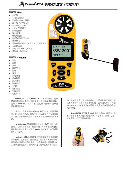
NK4500手持气象站(可测风向)NK4500特点z 三行图表显示,操作范围广泛z 能够存储1400个数据,并下载到电脑上 z 用户可定仪屏幕z 背光灯显示,可提供照明z 采用2节AAA 电池供电,电池可更换 z 两种省电模式延长电池寿命,电池平均寿命为400小时 z 可根据用户需要,选配蓝牙功能 z 防水防震,小巧、坚固、耐用 z 选配附件,可测风向z 支持英语、法语、意大得语、西班牙语、德语5种语言 z显示最大最小平均风速NK4500可测量参数z 当前风速z 最大风速z 最小风速 z 空气温度 z 相对湿度 z 气压 z 海拔z 横风/逆风 z 风寒 z 热力指数 z 露点温度 z 湿球温度 z密度高度Kestrel 4500便携式气候测量仪是一种高精度、耐用的小型仪器,它使用高精度超轻型宝石轴承叶轮来测量风速,启动风速低。
NK4500手持式风速仪(带风向) NK4500具有NK4000的所有性能,能够精确测量风速、温度、相对湿度、大气压和其他参数。
另外,NK4500具有一个内置的数字指南针,能够测量和显示风向值。
当设定一个参照物时,NK4500能够自动计算侧风、顺风和逆风风速,如果将其和Kestrel 风向标装置组合,就可以在数秒内建立一个记录气象数据的小型气象站。
NK 4500是旋转风杯式风速仪,体积小巧,方便携带。
采用高精度轴承,轻量叶轮,可精确测量风速值,即便是在风速很小(低至0.3m/s )的情况下。
如果叶轮损坏,可更换。
本页已使用福昕阅读器进行编辑。
福昕软件(C)2005-2009,版权所有,仅供试用。
NK4500手持气象站(可测风向)NK4500基本技术参数测量项目测量范围精度分辨率m/s 风速 0.4-40m/s±3% 0.1空气温度 -29℃-70℃1℃ 0.1℃相对湿度 0-100% 3% 0.1气压300~1100hPa 1.5 hPa/mb 0.1 hPa/mb15m 1m 海拔 -2000m-9000m横风、逆风 3.8 m/s -40 m/s 5% 0.1 m/s风寒0.4-40 m/s, -45.6-10.0 °C1℃ 0.1℃2℃ 0.1℃热力指数21.1-54.4 °C, 0-100%RH露点温度-29.0-70.0 °C, 20.0-95.02℃ 0.1℃%RH2℃ 0.1℃湿球温度 0-37.8℃, 5.0-95.0%RH, -2000.0-9000.0hPa, <6000 m密度高度0.0 - 37.8 °C, 5.0-95.075m 1m%RH, -2000-9000 hPa,<6000 m风向 0-360°5°1°自动关机功能可设置为15分钟或60分钟后自动关机操作温度 -45℃-125℃LCD和电池温度 -10℃-55℃电源2节7号电池,可用400个小时尺寸 127m m*45mm*28mm重量 102g可选附件风向标,用来测量风向,迷你三脚架,数据线证书每一个Kestrel风速仪都具有一个COC认证证书保证5年五NK4500产地:美国。


The information in this operator's manual is limited in application to the Honda GB4500 grass-bagging kit andYou CAN be HURT if you don't follow instructions.Y our equipment or other property can be damaged if you don't follow instructions.Honda side-blower and grass-bagging kits are designed to give safe and dependable service if operated according to instructions. Operating this equipment requires special effort on your part to ensure your safety and the safety of others.Careless operation or misuse can cause injury or property damage. Read and understand this owner's manual before operating this equipment.If a problem should arise, or if you have any questions about your equipment, see an authorized Honda lawn tractor dealer.1. SAFETYRead all safety instructions before operating the equipment.OBJECTS MAY BE THROWN FROM MOWER.DO NOT OPERATE MOWER UNLESS. ,GRASS CATCHER IS ATTACHED.\OBJECTS1. SAFETY SAFETY INFORMATIONFor your safety and the safety of others, pay special attention to these precautions:Operator ResponsibilityKeep the tractor in good operating condition. Operating a tractor in poor or questionable conditioncould result in serious injury.Be sure all safety devices are in working order and warning labels are in place. These items are installed for your safety.Know how to stop the engine and attachments quickly in case of emergency. Understand the use of all controls.Be sure that anyone who operates the tractor receives proper instruction. Allowing anyone, especially children, to operate the tractor without proper instruction may result in injury.Allowing passengers to ride on the tractor or any of its attachments may cause the tractor to tip over.Full grass bags may unbalance the tractor on steep hills. Before going up a hill, make sure the grass bags are no more than half full.Wear sturdy, full coverage footwear. Operating the tractor barefoot, or with open-toe shoes or sandals increases your risk of injury.Dress sensibly. Loose clothing may get caught in moving parts, increasing your risk of injury.The blower drive belt and pulleys can injure you. Be sure the blower belt cover is in place before operating the tractor.Be alert. Operating the tractor when you are tired, ill, or under the influence of alcohol or drugs may result in serious injury.Keep all persons and pets away from the operating area.Child SafetySerious injury or death can occur if a child falls off the tractor or runs into the tractor's path and isBlade HazardsThe blades are sharp and turn at high speed. Accidental contact can cause serious injury.Keep hands and feet away from the mower deck while the engine is running.Before operating the tractor, be sure the hopper top, grass bags, and grass bag chutes are in place, or that the side-discharge chute is down.Disengage the Power Take Off and shut off the engine, before opening the hopper top, or removingDisengage the Power Take Off (P.T.O.) to stop the blades before crossing a gravel driveway or any other area with loose stones.Broken pieces thrown from worn or damaged blades can cause serious injury. Always inspect the blades before using the tractor.Always inspect the mower deck and blades for damage after striking a foreign object. Repair or replace any damaged parts before continued use Always replace bent blades; do not attempt to straighten them.Fire HazardsDry grass and leaves are flammable.An accumulation of dry grass and leaves around the engine, the exhaust system, or on top of the mower deck (especially around the pulleys) may ignite.Always empty the grass bags when you finish mowing, even if they are not full. Stored lawn clippings are a fire hazard.'42.SERVICEGRASS BAG REMOVAL AND INSTALLATIONObjects thrown by the blades can cause serious injury. Disengage the Power TakeOffbolt a t the base of theretaining band, and move the band up or down.Tighten the 6 mm flange bolt to a torque value of8.0 ft-lb (1.1 kg-m).Under normal mowing conditions, the left grassbag will fill first, then the right bag will fill.Empty the grass bags before they both becomefilled to capacity. If the bags become overfilled,grassmayHOPPER TOP HOOKRETAININGBAND2. SERVICECHUTE DISCONNECTION AND REMOVAL FOR CLEANINGObjects thrown by the blades can cause serious injury. Disengage the Power TakeOffshut off the engine, then disconnect the chutesections and use a stick to unclog them. It may notbe necessary to remove the lower chute to unclog it.Clean the inner surfaces of the chute sections andhopper top periodically. This will help to keep the grassclippings moving freely into the bags.CHUTE 7DRIVE BELT REPLACEMENTTake Offinch wing nuts and washers from the belt cover. Remove the belt cover.NOTE: There are two additional 1not to lose any of the washers.3. Remove t he two 6x 12I--114 INCH WASHERS2. SERVICEDRIVE B E L T REPLACEMENT (continued)Installation1. Install the replacement belt on the blower pulleys, then hook it onto the mower deck pulley. It is important to install the belt correctly; if the belt is reversed on the mower deck pulley, the blower will run backwards.The belt runs from the upper blower pulley to the outer side of the mower deck pulley (the side toward the discharge chute). The belt returns from the inner side of the mower deck pulley (the side toward the middle of the mower deck) to the lower blower pulley. Refer to the illustration on page 8.2. Install the cover plate on the blower assembly. Tighten the two 6 x 12 mm flange bolts to a torque value of 8.0 ft -lb (1.1and shut off the engine, before removingequipment.Removal1. Remove the grass bags (see page 6).2. Lift the bag support assembly, with hopper top andchutes, off the left and right mounting struts. 3. Remove the lower chute (see pageLEFT STRUTHITCH PLATE2.SERVICEBAG, HOPPER, CHUTE, AND BLOWER REMOVAL FOR SIDE-DISCHARGE MOWING (continued) InstallationInstall in reverse order of removal.When installing the bag support assembly on the left and right struts, insert the center strut pin in the tractor’s hitch plate hole (see pagebefore you can remove the blower. ForLOCK PINMOUNTINGBRACKETIO3. WARRANTY SERVICE Owner SatisfactionYour satisfaction and goodwill are important to your dealer and to us. All Honda warranty details are explained in the Distributor’s Limited Warranty. Normally, any problems concerning the product will be handled by your dealer’s service department. If you have a warranty problem that has not been handled to your satisfaction, we suggest you take the following action:Discuss your problem with a member of the dealership management. Often complaints can be quickly resolved at that level. If the problem has already been reviewed with the Service Manager, contact the Owner of the dealership or the General Manager.If your problem still has not been resolved to your satisfaction, contact the Power Equipment Customer Service Department of American Honda Motor Co., Inc.American Honda Motor Co., Inc.Power Equipment DivisionP.O.Box 100021Duluth, Georgia 30136-9421Telephone:。
西农云雀气象仪用来测风速,温度,湿度,露点,大气压力,BF 薄福,风寒指数,手持气象仪是一种高精度、耐用的小型气象仪器,它使用高精度超轻型宝石轴承叶轮来测量风速,启动风速低。
叶轮安放在强化玻璃塑料支架上,安装简单,更换方便。
仪器体积小,可以放入口袋中,有一个液晶显示屏幕,几乎可以在任何地方进行测量。
可以选择风速、平均风速和最大风速三种测量模式。
它可以随时切换测量单位:节、米/秒、公里/小时、米/小时或英尺/分钟。
该仪器外壳使用防潮等级为IP67的材料,具有密封、绝热、高精度的性能,即便是在风速很小的情况下,也能精确测量风速值。
旋转风杯式风速仪,体积小巧,方便携带。
采用标准锂电池,可更换,能保证操作至少300小时。
如果风速仪在超过45分钟都没有任何操作的话,将会自动切断电源。
能飘浮在水上。
便携式结构设计,采集器与传感器采用一体化设计理念,无需安装拆卸工作,开箱即可测量,可放在各种现场环境的随意位置监测使用(田间,树丛,建筑,山谷等),是目前为止使用最为便捷的气象观测站。
系统高度集成,体积小巧,携带方便,便于现场应急性气象服,可有效保证数据的及时性,准确性。
西安黄氏生物工程有限公司一体化的风向风速仪,使体积更加小巧。
方便用户将仪器携带到恶劣的环境中使用,测量精度高,稳定性可靠,产品技术指标符合气象观测规范要求,可以根据使用需要进行手持方式观测。
低功耗,绿色节能设计,内部采用节能模式设计,若用太阳能电池板供电方式,可保证在无电地区长期使用;外部采用抗恶劣环境结构设计,在恶劣的天气条件下不影响仪器的使用效率,可以在雷雨、风雪环境中持续不间断工作。
防尘、防潮等级达到国家标准。
Agilent 4500 系列 FTIR操作手册声明© Agilent Technologies, Inc. 2008–2013, 2017根据美国和国际版权法,未经Agilent Technologies, Inc. 事先许可和书面同意,不得以任何形式或通过任何方法(包括电子存储和检索以及翻译成其他语言)复制本手册的任何部分。
手册部件号0021-401版本2017 年10月,第十版Agilent Technologies Australia [M] Pty Ltd679 Springvale Road Mulgrave, VIC, 3170, Australia 保修本文档所含资料“按原样”提供,在以后的版本中若有更改,恕不另行通知。
此外,在适用的法律所允许的最大范围内,Agilent对与此手册相关的内容及其中所含的信息不作任何明示或默示的保证,包括但不限于为特定目的的适销性和适用性所作的默示保证。
Agilent 对提供、使用或应用本文档及其包含的任何信息所引起的错误或偶发或必然损坏概不负责。
如果 Agilent 与用户之间单独签定的书面协议中所含的保证条款与本文档中的条款冲突,则应以单独协议中的保证条款为准。
技术许可证本文档中描述的硬件或软件是根据许可证提供的,其使用或复制必须符合此类许可证的有关条款。
限制性权利的说明如果软件在美国政府的项目主合同和转包合同中使用,则所交付并许可使用的软件是DFAR252.227-7014(1995年 6 月)中定义的“商用计算机软件”,或FAR 2.101(a) 中定义的“商用品”,或FAR 52.227-19(1987年 6月)或任何同等机构法规或合同条款中定义的“限制性计算机软件”。
本软件的使用、复制或公布受Agilent Technologies标准商用许可条款的限制,非国防部(DOD) 机构和美国政府机构所受限制以FAR 52.227-19(c)(1-2)(1987 年6 月)中定义的“限制性权利”为准。
安东帕密度计4500参数
安东帕DMA 4500 M密度计以其高精度和高效率而受到广泛赞誉。
这款设备采用了突破性的U形振荡管原理,集成一体的参比振荡管,高精度的铂金温度计和全范围的黏度修正等特点,使其在每次测量时仅需要大约30秒的时间,并且能直接在三分钟内输出结果。
DMA 4500 M运用获得专利的脉冲激发方法,在全面了解振荡特性基础上,给出最稳定的密度测量结果。
这种方法采用黏度修正,效率是市场上其他同类产品的两倍。
DMA 4500 M密度计具有极高的准确度,可以以5位数的准确度测量密度和浓度。
它完全符合QM、GMP/GLP以及21 CFR Part 11的相关标准和规定,因此,它是啤酒和软饮料样品的首选测量设备。
无论是在化学品、药品、化妆品、石油产品、香料、生物燃料等不同行业与研究领域,DMA 4500 M都能提供可靠精确的密度和浓度测量。
HANDHELD ROTATING VANE ANEMOMETER C-17U H igh Accuracy (±1.0% of Reading)U R ugged Metal Probe and VaneU U ltra Low Sensitivity Down to 0.2 m/s (40 fpm)U M easure Airflow from -20 to 100°C (-4 to 212°F)U M inimum and Maximum Velocity CaptureU A nalog Voltage Output and Communication Options U N IST Calibration Included The Omega ® HHF141 rotating vane anemometer is a high-quality instrument providing highly accurate air velocity measurements in harsh environments via a user-friendly and intuitive interface. applications include manufacturing, laboratory, computer rooms, environmental control, flow hood monitoring, and other applications where precise air measurement is required.SPeCIFICATIONS Ranges: HHF141A: 25 mm (1") probe, 300 to 6800 FPm (1.5 to 35.00 mPS) HHF141B: 70 mm (23⁄4") probe, 40 to 7800 FPm (0.2 to 40.00 mPS)Accuracy: ±1.0% of reading ±1-digit Resolution: 1 FPm or 0.01 mPS Display: 12.7 mm (0.5”) LCD, 4-digits, with LeD backlight Operating Temperature: Instrument: 0 to 50°C (32 to 125°F) Probe: -20 to 100°C (-4 to 212°F)Power Supply: 3 “aa” alkaline batteries (included)Battery Life: approximately 150 hours Dimensions: Instrument: 165 x 83 x 38 mm (6.5 x 3.25 x 1.5") HHF140A: 25 mm (1") diameter head HHF140B: 70 mm (2.75") diameter head Cable: 1.5 m (5')Outputs (Optional): USB or 0 to 5 Vdc Comes complete with vane probe [25 or 70 mm (1 or 234") depending on model], 3 extension rods (flexible, straight and with handle), 1.5 m (5') cable, 3 “AA” alkaline batteries, hard carrying case, NIST calibration certificate and operator’s manual.For units with a protective boot and splash proof seals add suffix “-PB ” to model number, for additional cost.For units with USB communications add suffix “-USB ” to model number, for additional cost.For units with a 0 to 5 Vdc voltage output add suffix “-V ” to model number, for additional cost.Ordering Examples: HHF141B-USB , anemometer with 70 mm (23⁄4") vane and USB communications.HHF141A-V , anemometer with 25 mm (1") vane and a voltage output.HHF141A shown smaller than actual size.Rugged 25 mm (1") metal probe (included)Standard。