E02158GJ型保护板原材料规格书A
- 格式:doc
- 大小:1.05 MB
- 文档页数:16
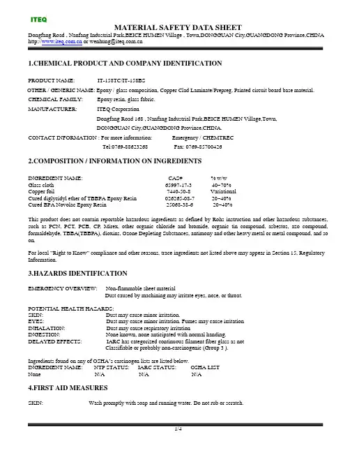
1.CHEMICAL PRODUCT AND COMPANY IDENTIFICATIONPRODUCT NAME: IT-158TC/IT-158BSOTHER / GENERIC NAME: Epoxy / glass composition, Copper Clad Laminate/Prepreg, Printed circuit board base material. CHEMICAL FAMILY: Epoxy resin, glass fabric.MANUFACTURER: ITEQ CorporationDongfang Road 168 , Nanfang Industrial Park,BEICE HUMEN Village,Town,DONGGUAN City,GUANGDONG Province,CHINA.CONTACT INFORMATION : For more information: Emergency / CHEMTRECPOSITION / INFORMATION ON INGREDIENTSINGREDIENT NAME: CAS# % w/wGlass cloth 65997-17-3 40~70%Copper foil 7440-50-8 VariationalCured diglycidyl ether of TBBPA Epoxy Resin 026265-08-7 20~40%Cured BPA Novolac Epoxy Resin 25068-38-6 20~40%This product does not contain reportable hazardous ingredients as defined by Rohs instruction and other hazardous substances, such as PCN, PCT, PCB, CP, Mirex, other organic chloride and bromide, organic tin compound, asbestos, azo compound, formaldehyde, TBBA(TBBPA), dioxins, Ozone Depleting Substances, antimony and other heavy metal or metal compound, and so on.For local ”Right to Know” compliance and other reasons, trace ingredients not listed above may appear in Section 15, Regulatory Information.3.HAZARDS IDENTIFICATIONEMERGENCY OVERVIEW: Non-flammable sheet materialDust caused by machining may irritate eyes, nose, or throat.POTENTIAL HEALTH HAZARDS:SKIN: Dust may cause minor irritation.EYES: Dust may cause minor irritation. Fumes may cause irritationINHALATION: Dust may cause respiratory irritationINGESTION: None known, none anticipated with normal handing.DELAYED EFFECTS: IARC has categorized continuous filament fiber glass as notClassifiable or probably non-carcinogenic (Group 3 ).Ingredients found on any of OSHA’s carcinogen lists are listed below.INGREDIENT NAME: NTP STATUS: IARC STATUS: OSHA LISTNone N/A N/A N/A4.FIRST AID MEASURESSKIN: Wash promptly with soap and running water. Do not rub or scratch.******************.cnIf irritation persists, consult physician.Remove contaminated clothing and wash thoroughly before reuseEYES: Flush immediately with plenty of low-pressure water for at least 20Minutes.Do not rub or scratch.If irritation persists, consult physician.INHALATION: Move to fresh air.Consult physician.INGESTION: If large amounts are ingested, consult physician.ADVICE TO PHYSICIAN:Treat symptomatically5.FIRE-FIGHTING MEASURESFLASH POINT: N/AFLASH POINT METHOD: N /AAUTOIGNITION TEMP: Not determined.UPPER FLAME LIMIT: N/ALOWER FLAME LIMIT: N/AFLAME PROPAGATION RATE: UL 94 V-0OSHA FLAMMABILITY CLASS: N/AEXTINGUISHING MEDIA: Water, CO2, foam, dry chemicalUNUSUAL FIRE ANDEXPLOSION HAZARDS: May give off toxic hydrogen bromide fumes when thermally decomposed. SPECIAL FIRE-FIGHTINGPROCEDURES: Wear proper protective equipment and self-contained breathing apparatus.6.ACCIDENTAL RELEASE MEASURESRESPONSE TO RELEASE: If material is not contaminated, return to container for use.If material is contaminated, pick up and place in container for disposal.Material is an article. Spill or release to the environment is unlikely.7.HANDLING AND STORAGENORMAL HANDLING: Always wear recommended personal protective equipment.STORAGE: Store in a cool dry place.8.ENGINEERING CONTROLS / PERSONAL PROTECTIONENGINEERING CONTROLS:VENTILATION: Adequate ventilation should be provided to keep dust concentrationswithin acceptable exposure limits. Discharge from the ventilationsystem should comply with applicable air pollution control regulation GENERAL: Eyewash fountains and safety showers should be easily accessible. PERSONAL PROTECTIVE EQUIPMENT:SKIN PROTECTION: Impervious gloves and clothing should be worn for prolonged orRepeated contact.EYE PROTECTION: Safety glassesRESPIRATORY PROTECTION:Atmospheric levels of fibrous glass, copper, and other dusts should bemaintained below recommended exposure guidelines.If airborne contaminant is likely to exceed acceptable limits, use aNIOSH-approved respirator.ADDITIONAL: N/A。
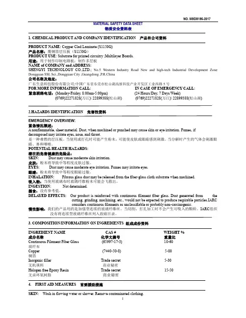
MATERIAL SAFETY DATA SHEET物质安全资料表1.CHEMICAL PRODUCT AND COMPANY IDENTIFICATION 产品和公司资料PRODUCT NAME: Copper Clad Laminate (S1150G)产品名称:覆铜箔层压板(S1150G)PRODUCT USE: Substrate for printed circuitry ;Multilayer Boards.用途:用于制作印制电路板;制作多层板NAME of COMPANY and ADDRESS:SHENGYI TECHNOLOGY CO.,LTD.; No.5 Western Industry Road New and high-tech Industrial Development Zone Dongguan SSL Sci.,Dongguan City ,Guangdong ,P.R.China公司名称及地址:广东生益科技股份有限公司;中国广东省东莞市松山湖高新科技产业开发区工业西路5号FOR MORE INFORMATION CALL: IN CASE OF EMERGENCY CALL:紧急联络电话:(Monday-Friday, 8:00am-5:00pm) (24 Hours/Day, 7 Days/Week)(0769)22271828(万江)\ 22899388(松山湖) (0769)22271828(万江)\ 22899388(松山湖)2.HAZARDS IDENTIFICATION 危害性资料EMERGENCY OVERVIEW:紧急情况概述:A nonflammable, sheet material. Dust, when machined or punched may cause skin or eye irritation. Fumes, if decomposed may irritate eyes, nose, and throat.是一种难燃的层压板。
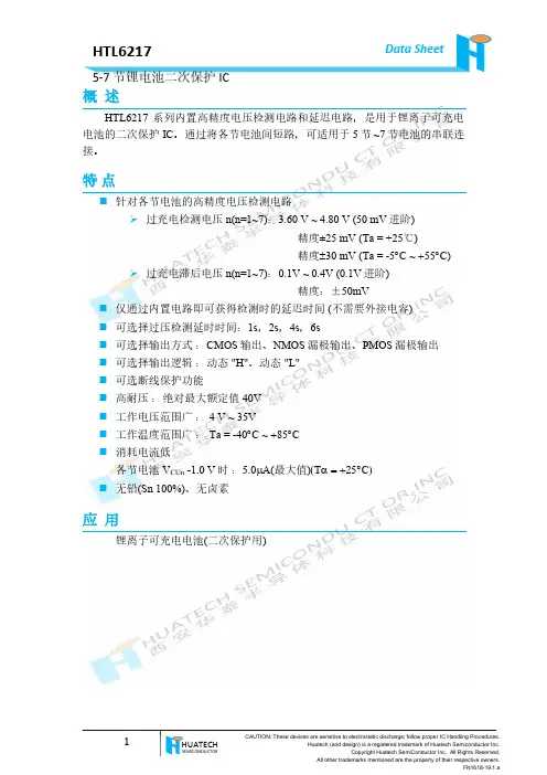
5-7节锂电池二次保护IC概述HTL6217系列内置高精度电压检测电路和延迟电路,是用于锂离子可充电电池的二次保护IC。
通过将各节电池间短路,可适用于5节 ~7节电池的串联连接。
特点⏹针对各节电池的高精度电压检测电路过充电检测电压n(n=1~7):3.60 V ~ 4.80 V (50 mV进阶)精度±25 mV (Ta = +25℃)精度±30 mV (Ta = -5︒C ~ +55︒C) 过充电滞后电压n(n=1~7):0.1V ~ 0.4V (0.1V进阶)精度:±50mV⏹仅通过内置电路即可获得检测时的延迟时间 (不需要外接电容)⏹可选择过压检测延时时间:1s,2s,4s,6s⏹可选择输出方式:CMOS输出、NMOS漏极输出、PMOS漏极输出⏹可选择输出逻辑:动态 "H"、动态 "L"⏹可选断线保护功能⏹高耐压:绝对最大额定值40V⏹工作电压范围广: 4 V ~ 35V⏹工作温度范围广: Ta = -40︒C ~ +85︒C⏹消耗电流低各节电池V CUn -1.0 V时:5.0μA(最大值)(Tα = +25︒C)⏹无铅(Sn 100%)、无卤素应用锂离子可充电电池(二次保护用)5-7节锂电池二次保护IC 典型应用电路1、7节串联VCCVC7VC6VC5VC4 VC3 VC2 VC1 VSSCHC HTL6217系列R VCC R1C VCCC6C5C4C3C2C1BAT7 BAT6 BAT5 BAT4 BAT3 BAT2 BAT1SC PROTECTORFETEB+EB-R7R6R5R4R3R2C7R H2R H1图1 7节串联外接元器件参数No. 元器件最小值典型值最大值单位1 R1 ~ R7 0.5 1 10 kΩ2 C1 ~ C7 0.01 0.1 1 μF3 C VCC0.1 1 10 μF4 R VCC0.05 0.5 1 kΩ5 R H1,R H2 1 5 10 MΩ注意:1.上述参数有可能未经预告而改变。
Product feature :•0603 (1608 metric) compact design utilizes less board space•Halogen free, lead free and RoHS compliant•High inrush withstand capability •Fast-acting performance•Ampacity alpha mark on fuse for easy identification•Standard termination design for easy solderability•Compatible with standard lead-free solder reflow and wave soldering processes•Excellent environmental integrityApplicationsFor secondary circuit protection in spaceconstrained applications:• LCD Backlight inverters • Digital cameras • DVD Players • Bluetooth headsets •Battery packsAgency information•cURus Recognized Guide and Card JDXY2/JDYX8, File E19180Packaging•TR - Packaging code suffix for tape-and-reel (8 mm wide tape on 178mm diameter reel -specification EIA 481-1)•Quantity = 5000 fusesCC06HHigh I 2t Chip™ 0603 size fuses7 014PbTechnical Data 4346Effective June 2017CC06H High I2t Chip™ 0603 size fusesElectrical characteristicsAmp Rating% of Amp Rating Opening Time 1-8A100 4 Hours1-7A2001-60 Seconds1-8A250 5 Seconds Max SpecificationsPart NumberAmpRating5VoltageRating(Vdc)InterruptingRating1, 4(A)Typical ColdResistance2(Ω)TypicalPre-Arcing3(I2t)TypicalVoltageDrop(mV)TypicalPowerDissipation(W)AlphaMarkingAgencyInformation(cURus)CC06H1A132500.250.023100.32B x CC06H1.5A 1.532500.130.072500.38H x CC06H2A232500.0680.141700.38K x CC06H2.5A 2.532500.050.251550.38L x CC06H3A332500.0350.301300.38O x CC06H3.5A 3.532500.0230.501000.35R x CC06H4A432500.020.81100.45S x CC06H5A532500.013 1.6950.48T x CC06H6A632500.0076 2.6800.48V x CC06H7A732500.0056 3.3800.56X x CC06H8A832/2450/800.0040 4.5750.60Z x1.DC Interrupting Rating (measured at rated voltage, time constant of less than 50 microseconds, battery source).2.DC Cold Resistance are measured at <10% of rated current in ambient temperature of 20°C -FOR REFERENCE ONLY - CONTROLLED VALUES HELD BY PLANT AND SUBJECT TO CHANGE WITHOUT NOTICE.3.Typical Pre-arcing I2t are measured at rated DC voltage, 10Incurrent (not to exceed interrupting rating).4.The insulation resistance after breaking capacity test is higher than 0.1MΩ when measured by 2X rated voltage.5.Device designed to carry rated current for 4 hours minimum. An operating current 80% or less of rated current is recommended,with further design derating required at elevated ambient temperature. See Temperature Derating Curve on next page./el ectronics23Technical Data 4346Effective June 2017CC06HHigh I 2t Chip™ 0603 size fuses Time-current curves — average melt/el ectronics4Technical Data 4346Effective June 2017CC06HHigh I 2t Chip™ 0603 size fusesI 2t vs. time curvesI 2t (A 2s )5Technical Data 4346Effective June 2017CC06HHigh I 2t Chip™ 0603 size fuses I 2t vs. current curvesI 2t (A 2s )/el ectronics6Technical Data 4346Effective June 2017CC06HHigh I 2t Chip™ 0603 size fusesT emperature derating curve Product characteristicsOperating temperature -40 °C to +85 °C , with proper derating factor applied Storage temperature -40 °C to +85 °CLoad humidity MIL-STD-202G, Method 103B (1000 hr @ +85 °C / 85% RH & 10% rated current)Moisture resistance MIL-STD-202, Method 106E (50 cycles)Thermal shock MIL-STD-202, Method 107D (-65 °C to +125 °C, 100 cycles)Vibration testMIL-STD-202, Method 204D, Test Condition D (10-2,000 Hz)Mechanical shock resistance MIL-STD-202, Method 213B (3000 G / 0.3 ms)Salt spray resistance MIL-STD-202, Method 101, Test Condition B (48 h ou r exposure)Insulation resistance The insulation resistance after breaking capacity test is higher than 0.1 M Ω when measured by 2X rated voltage SolderabilityJ-STD-002C Method B1 (Dip and Look Test), Method G1 (Wetting Balance Test), Method D (Resistance to Dissolution / Dewetting of Metalization)Resistance to soldering heat MIL-STD-202, Method 210F (Solder dip +260 °C, 60 seconds / Solder Iron +350 °C, 3-5 seconds)High temperature life test MIL-STD-202G, Method 108A (1000 Hours @ +70 °C & 60% rated current)Resistance to solventsMIL-STD-202, Method 215KDimensions - mm (in)Drawing not to scale.0.47 ± 0.08Pad layoutA 0B 0D 0E 1E 2F G P 0P 1P 2T W 0.95±0.051.80±0.051.50+0.10,-0.01.75±0.106.25±0.303.50±0.050.75min.4.00±0.104.00±0.102.00±0.050.060±0.058.00±0.20*Tolerance for peak profile temperature (T p ) is defined as a supplier minimum and a user maximum.** Tolerance for time at peak profile temperature (t p ) is defined as a supplier minimum and a user maximum.Solder reflow profileTechnical Data 4346Effective June 2017CC06HHigh I 2t Chip™ 0603 size fusesLife Support Policy: Eaton does not authorize the use of any of its products for use in life support devices or systems without the express written approval of an officer of the Company. Life support systems are devices which support or sustain life, and whose failure to perform, when properly used in accordance with instructions for use provided in the labeling, can be reasonably expected to result in significant injury to the user.Eaton reserves the right, without notice, to change design or construction of any products and to discontinue or limit distribution of any products. Eaton also reserves the right to change or update, without notice, any technical information contained in this bulletin.EatonElectronics Division 1000 Eaton Boulevard Cleveland, OH 44122United States/electronics © 2017 EatonAll Rights Reserved Printed in USAPublication No. 4346 BU-SB14476 June 2017Eaton is a registered trademark.All other trademarks are property of their respective owners.。
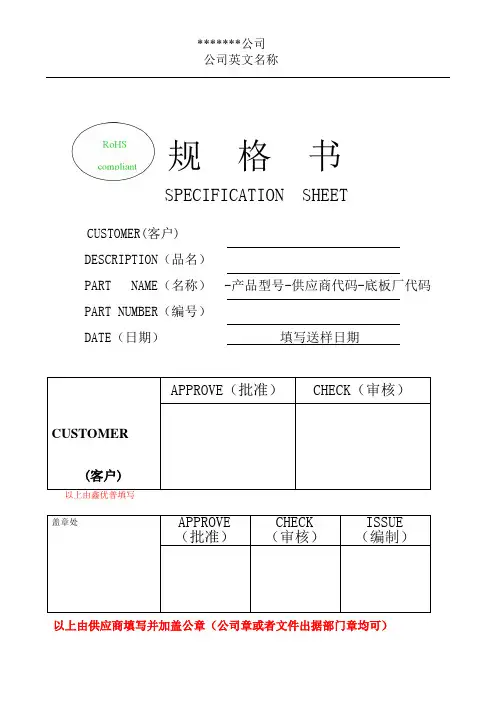
规 格 书SPECIFICATION SHEETCUSTOMER(客户) DESCRIPTION (品名)PART NAME (名称) -产品型号-供应商代码-底板厂代码 PART NUMBER (编号) DATE (日期)填写送样日期CUSTOMER(客户)APPROVE (批准)CHECK (审核)以上由鑫优普填写 盖章处APPROVE (批准)CHECK (审核)ISSUE (编制)以上由供应商填写并加盖公章(公司章或者文件出据部门章均可)更改目录序号更改项类别变更内容变更原因1 无更改初版2 增加ID电阻更改前无ID电阻客户要求(2011.08.29)更改后有10KΩ ID电阻3 更改前更改后4 更改前更改后5 更改前更改后6 更改前更改后7更改前更改后以上填写要求:1)第一次送样,按序号1中项目填写2)以后每次更改需要完整填写更改项目更改前更改后内容及变更原因及注明日期3)第二次更改必须保留第一次更改的内容第三次更改必须保留第一次第二次更改内容,依次类推1-1. 原理图Schematic diagram :1-2元件清单PCB Parts lis注明:1)ROHS 报告号码必须填写,且为正确并在有效使用范围内的ROHS 报告号码2)元件件厂商填写元器件厂家,而不是代理商名称,厂家送样承认后不能做任何更改(包括底板 IC MOS 电阻 电容)3)规格包括元器件值 公差 耐压值 功率等主要参数 4)以上红色部分只是范例,按实际填写即可序号 元件编号 元件名称规格封装形式 配量 RoHS 报告号 厂商1 PCB 电路板 注明PCB 尺寸及公差 注明PCB 工艺(如黑油喷锡板 绿油镀金板) 1 PCS SH901755/CHEM 吉瑞达2 U2 MOS 管 8205A SOT-23-6 1 PCSSH9197409/CHEM富晶 3 U1 控制IC DW01+ SOT-23-6 1 PCS CANEC1001922017 富晶 4 R1 贴片电阻 SMD 100Ω±5% 0603 1 PCS KA/2010/10205 国巨 5 R2 贴片电阻 SMD 1K Ω±5% 0402 1 PCS KA/2010/10205 国巨 6 R3 贴片电阻SMD 10K Ω±5%0603 1 PCS KA/2010/10205 国巨 7 C1 贴片电容 10V 0.1UF (+80%-20%) 06031 PCS KA/2010/10205国巨 8镍块B+/B-2.8*2.2*0.3MM(-0.1MM)2PCS9 五金镀金五金或贴片五金贴写五金数量 尺寸及公差五金工艺(镀金 钴金 沉金等) 五金镀金厚度 五金要求等例如:3PCS (3*2*0.6)-0.05mm 贴片五金 五金镀金厚度0.1um 48H 盐雾测试不氧化 冲压五金反贴(不注明反贴就是正贴 例如:镀金五金 镀哑金 五金镀金厚度0.1um 48H 盐雾测试不氧化1-3焊盘描述Pad descriptionSymbol DescriptionP+/P- Positive/ Negative connection pad of packB+/B- Positive/ Negative connection pad of batteryT Connection pad of 10K以上只需要标识出B+ B- COM B1 B2 B3…及输出P+ P- T端即可,不需要标识IC MOS 元器件位置1-4尺寸dimensionsNote: (unit: mm)1、No mark tolerances: +/-0.12、Material : FR-43、Total Thickness: 0.8 +0.1(根据要求填写)抓打样详细尺寸图纸1-5 PCB 走线图Circuit PCB diagramABCDDiagram of PCB fit togetherNOTE :A----Top overlayerB---- Toplayer C---- Bottomlayer D----Bottom overlayer1-6 技术参数Technical Parmeter1.参数ParmeterDW01+ Ta=25℃值Value参数 Parameter最小Min 标准Type 最大Max 单位过充检测电压4.25V 4.30v 4.325V VOvercharge Testing Voltage过充恢复电压4.05V 4.10V 4.15V VOvercharge renew voltage过充保护延迟时间80ms 200s ms Overdischarge protect Voltage过放检测电压2.3V 2.40V 2.5V VOverdischarge testing Voltage过放恢复电压2.9V3.00V 3.1V VOverdischarge renew voltage过放保护延迟时间Overdischarge20ms 60ms ms protect prolong time过流保护检测电压0.147V 0.15V 0.153V mvOvercurrent testing Voltage过流保护延迟时间10ms 20ms ms Over current prolong time短路保护检测电压1.25V 1.35V 1.45V VShort testing Voltage短路保护延迟时间5μs 50μs μs Short protect prolong time内阻 Resistance60mΩmΩ以上根据IC配置正确填写测试:审核:日期:最终判定:样品检测报告样品型号: 配置: DW01+ \ 8205A \1K 测试日期测试环境温度:15 ℃湿度:65%保护板参数范围值:( NTC注明当前测试温度下阻值范围值)自耗电(uA) 过充 (V) 过充恢复(V) 过放 (V) 过放恢复(V) 过流(A) 内阻(mΩ)ID(15 ℃) 2-6 4.25-4.35 4.05-4.15 2.3-2.5 2.9-3.1 2.1-6 20-60 1K测试仪器:泰斯锂电保护板测试仪序号过充 (V) 过充恢复(V)过放 (V) 过放恢复(V) 过流(A) 内阻(mΩ)自耗电(uA)ID 判定1. 4.321 4.0952.3353.05 3.27 53 3.10 1K ok2. 4.326 4.102 2.3553.01 3.22 53 3.45 1K ok3. 4.324 4.106 2.3650 2.97 3.21 54 3.90 1K ok4. 4.322 4.098 2.320 3.02 3.36 55 4.10 1K ok5. 4.315 4.104 2.395 2.96 3.33 55 4.10 1K ok PCB尺寸标准:34±0.3*5.3±0.1*0.8mm±0.10PCB尺寸测量: 1: 2: 3:4: 5:测试:审核:日期:客户测试数据:序号过充(V)过充恢复(V) 过放 (V) 过放恢复(V) 过流(A) 内阻(mΩ)自耗电(uA)ID 判定12345PCB尺寸测量: 1: 2: 3:4: 5:。
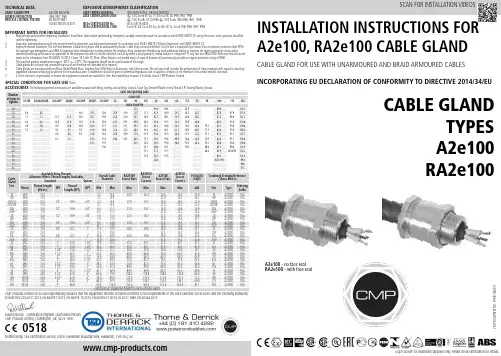
CABLE GLAND FOR USE WITH UNARMOURED AND BRAID ARMOURED CABLESINCORPORATING EU DECLARATION OF CONFORMITY TO DIRECTIVE 2014/34/EUTECHNICAL DATACABLE GLANDTYPES A2e100RA2e100INSTALLATION INSTRUCTIONS FOR A2e100, RA2e100 CABLE GLANDGlasshouse Street • St. Peters • Newcastle upon Tyne • NE6 1BSTel: +44 191 265 7411 • Fax: +44 1670 715 646E-Mail:********************************.uk•Web:Notified Body: Sira Certification Service, Unit 6, Hawarden Industrial Park, Hawarden, CH5 3US, UK0518CABLE GLAND TYPE : A2e100, RA2e100INGRESS PROTECTION: IP66, IP67, IP68PROCESS CONTROL SYSTEM : BS EN ISO 9001ISO/IEC 80079-34:2011C M PD o c u m e n t N o . F I 493 I s s u e 4Logo’s shown for illustration purposes only. Please check certification for detailsEN 60079-0:2012/A11:2013, EN 60079-7:2015, EN 60079-15:2010, EN 60079-31:2014, BS 6121:1989, EN 62444:2013David Willcock - Certification Engineer (Authorised Person)CMP Products Limited, Cramlington, UK, NE23 1WHSCAN FOR INSTALLATION VIDEOSEXPLOSIVE ATMOSPHERES CLASSIFICATIONATEX CERTIFICATION No : SIRA16ATEX3165, SIRA16ATEX4020ATEX CERTIFICATION CODE : ^ II 2G Ex eb IIC Gb, II 1D Ex ta IIIC Da IP66, IP67, IP68^ II 3G Ex nRc IIC Gc IP66 ^ I M2 Ex eb I Mb IP66, IP67, IP68IECEx CERTIFICATION No : IECEx SIR 16.0053IECEx CERTIFICATION CODE : Ex eb IIC Gb, Ex ta IIIC Da, Ex nRc IIC Gc, Ex eb I Mb IP66, IP67, IP68A2e100 - no face seal RA2e100 - with face seal1. Read all instructions before beginning installation. Installation shall only be performed by competent, suitably trained personnel (in accordance with EN/IEC 60079-14) using the correct tools; spanners should be used for tightening.2.Inspection and maintenance shall only be performed by competent, suitably trained personnel (in accordance with EN/IEC 60079-14 (Initial Inspection) and EN/IEC 60079-17).3.Ingress Protection Statement; The interface between a cable entry device and its associated enclosure / cable entry cannot be defined. It is the user’s responsibility to ensure that a minimum protection level (IP54 for explosive gas atmospheres and IP6X for explosive dust atmospheres) is maintained at the interface. Entry component threads may need additional sealing to maintain the ingress protection rating and/orrestricted breathing performance as applicable to the equipment to which it will be attached, such as by either a sealing washer, thread sealant or integrated ‘O’ ring face seal (RA2e100). Reference should also be made to the information from EN 60079-14:2014, Clause 10, Table 10, (Note: When fitted to a threaded entry, all tapered threads will automatically provide an ingress protection rating of IP6X).4. The standard product temperature range is -60°C to +130°C. The equipment should not be used outside of this range.5. Cable glands do not have any serviceable parts and are therefore not intended to be repaired.6. Cable glands are manufactured from Brass, Nickel Plated Brass, Stainless Steel, Mild Steel or Aluminium, with Silicone seals. The end user shall consider the performance of these materials with regard to attack by aggressive substances that may be present in the hazardous area. Consideration should be given to potential degradation due to galvanic corrosion at the interface of dis-similar metallic materials.7.It is the end user’s responsibility to ensure the equipment materials are suitable for their final installation location. If in doubt consult CMP Products Limited.IMPORTANT NOTES FOR INSTALLERSSPECIAL CONDITIONS FOR SAFE USE None INSTALLATION INSTRUCTIONS FOR CMP CABLE GLAND A2e100, RA2e100CABLE GLAND COMPONENTS - It is not necessary to dismantle the cable gland any further than illustrated below 1. Entry Item 2. Seal 3. Seal NutPLEASE READ ALL INSTRUCTIONS CAREFULLY BEFORE BEGINNING THE INSTALLATION1. It is not necessary to dismantle the gland any further than illustrated below.where required to reveal the insulated conductors.4. Slacken the seal nut (3) to relax the seal (2).5. Only using finger pressure, tighten the seal nut until light resistance to tightening is met.Then either use the seal tightening guide tape or table on the rear of the page to determine how much further to tighten the seal using a spanner (using the outer seal tightening guide is recommended).Wrap the seal tightening guide tape around the cable to show the amount of spanner turns needed (as shown here). Make sure the correct side of the seal tightening guide tape is used depending on the cable gland size.。
编号:JK/J.JK-BXAXSXP.09版本:2.2锂电池主动均衡保护板JK-BD6AxxS-6P/JK-BD6AxxS-8PJK-BD6AxxS-10P/JK-BD6AxxS-15PJK-BD6AxxS-20P/JK-B1AxxS-15PJK-B2AxxS-15P/JK-B2AxxS-20P使用维护说明书成都极空科技有限公司产品保修条款产品名称:锂电池智能保护板保修期限:壹年首先,感谢您购买成都极空科技有限公司推出的锂电池智能保护板产品。
成都极空科技有限公司对由本公司出售的硬件产品和附件提供质量保修,保修期限如上所示。
在保修期内如果出现因质量原因而产生故障,公司在收到关于产品故障的通知并经查验核实后,有权选择维修或整套更换产品。
整套更换的产品可是新件或接近新件。
1.成都极空科技有限公司保证产品经过充分测试。
2.成都极空科技有限公司不保证在产品修理过程中产品可不中断地使用。
但公司应保证在合理的期限内修理好发生故障的产品。
3.产品保修期从产品发运之日或由成都极空科技有限公司开始安装之日开始计算。
如果因用户的进度安排或延后使公司产品在发运之日后的30天内仍未开始安装,产品保修期从发运之日后的第31天开始计算。
4.成都极空科技有限公司对任何下列情况而导致的产品故障和损坏不提供免费保修:(a)错误的使用或不适当的维护;(b)非成都极空科技有限公司提供的软件、附件、部件或其它物品;(c)未经许可的拆卸、修改和错误使用;(d)超过产品技术规格指明的范围使用;(e)不适当的运输、搬运和存贮;(f)其它非质量原因造成的故障或损坏(如地震、战争、交通事故等)。
在法律允许的范围内,上述保修条款是唯一明确的,同时没有任何其它的保修条款,不论是书面的或口头的。
明确表示拒绝承认任何隐含的保修条款和商业条款。
版权声明所有成都极空科技有限公司出售的产品或随同硬件产品出售的软件和文件,其版权属成都极空科技有限公司所有,成都极空科技有限公司保留产品和文件方面的所有版权。

Table Of ContentsTable Of Contents . . . . . . . . . . . . . . . . . . . . . . . . . . . . . . . . . . . . . . . . . . . . . . . . . . . . . . . . . . . . . . . . . . . . . . . .2 Abstract . . . . . . . . . . . . . . . . . . . . . . . . . . . . . . . . . . . . . . . . . . . . . . . . . . . . . . . . . . . . . . . . . . . . . . . . . . . . . . .3 Introduction . . . . . . . . . . . . . . . . . . . . . . . . . . . . . . . . . . . . . . . . . . . . . . . . . . . . . . . . . . . . . . . . . . . . . . . . . . . .4 Lead Free Legislation . . . . . . . . . . . . . . . . . . . . . . . . . . . . . . . . . . . . . . . . . . . . . . . . . . . . . . . . . . . . . . . .5 European Union Directive . . . . . . . . . . . . . . . . . . . . . . . . . . . . . . . . . . . . . . . . . . . . . . . . . . . . . . . . . . . . .5 Japanese Ministry of Trade . . . . . . . . . . . . . . . . . . . . . . . . . . . . . . . . . . . . . . . . . . . . . . . . . . . . . . . . . . . .5 US Legislation . . . . . . . . . . . . . . . . . . . . . . . . . . . . . . . . . . . . . . . . . . . . . . . . . . . . . . . . . . . . . . . . . . . . .5 Bourns Commitment to Lead Free Components . . . . . . . . . . . . . . . . . . . . . . . . . . . . . . . . . . . . . . . . . . . . . .5 Bourns® Lead Free Surface Mount Multifuse® Polymer PTC Product Portfolio . . . . . . . . . . . . . . . . . . . . . . . . . . . . .6 Category 2 Typical Coating Durability for Non-Tin and Non-Tin Lead Finishes . . . . . . . . . . . . . . . . . . . . . . . . .6 Category 3 Typical Coating Durability Default for Tin and Tin Lead Finishes . . . . . . . . . . . . . . . . . . . . . . . . . .6 Multifuse® Surface Mount Component Terminations . . . . . . . . . . . . . . . . . . . . . . . . . . . . . . . . . . . . . . . . . .7 Part Number Explanation . . . . . . . . . . . . . . . . . . . . . . . . . . . . . . . . . . . . . . . . . . . . . . . . . . . . . . . . . . . . .7 Bourns® Lead Free Radial Multifuse® Polymer PTC Product Portfolio . . . . . . . . . . . . . . . . . . . . . . . . . . . . . . . . . . . .8 Part Number Explanation . . . . . . . . . . . . . . . . . . . . . . . . . . . . . . . . . . . . . . . . . . . . . . . . . . . . . . . . . . . . .8 Improved Heat Resistance . . . . . . . . . . . . . . . . . . . . . . . . . . . . . . . . . . . . . . . . . . . . . . . . . . . . . . . . . . . .9 Recommended Reflow Profiles . . . . . . . . . . . . . . . . . . . . . . . . . . . . . . . . . . . . . . . . . . . . . . . . . . . . . . . . .9 Lead Free Solder Paste . . . . . . . . . . . . . . . . . . . . . . . . . . . . . . . . . . . . . . . . . . . . . . . . . . . . . . . . . . . . . . .9 Cross-Sections of Fillet Shaped Solder Joints . . . . . . . . . . . . . . . . . . . . . . . . . . . . . . . . . . . . . . . . . . . . . . .10 Test Results . . . . . . . . . . . . . . . . . . . . . . . . . . . . . . . . . . . . . . . . . . . . . . . . . . . . . . . . . . . . . . . . . . . . . . . . . . .11 Terminal Strength Test Comparison Between Lead and Lead Free Plated Products . . . . . . . . . . . . . . . . . . . . .11 Terminal Strength Test of Lead Free Plated Products after Steam Aging . . . . . . . . . . . . . . . . . . . . . . . . . . . .12 Tin Whisker Growth Accelerated Test . . . . . . . . . . . . . . . . . . . . . . . . . . . . . . . . . . . . . . . . . . . . . . . . . . . .13 Solderability . . . . . . . . . . . . . . . . . . . . . . . . . . . . . . . . . . . . . . . . . . . . . . . . . . . . . . . . . . . . . . . . . . . . .14 Additional Testing . . . . . . . . . . . . . . . . . . . . . . . . . . . . . . . . . . . . . . . . . . . . . . . . . . . . . . . . . . . . . . . . .15 Conclusion . . . . . . . . . . . . . . . . . . . . . . . . . . . . . . . . . . . . . . . . . . . . . . . . . . . . . . . . . . . . . . . . . . . . . . . . . . . .16AbstractIn today’s environmentally conscious world there is a strong movement away from the use of lead in favor of alternative products.This is happening across all industry sectors.We have been introduced to lead free paint, lead free castings,lead free fuel and many other lead free products.As electronic goods become disposable commodities the electronics sector has become the principal driver of this trend.The majority of electronic companies are now evaluating lead free solders.Manufacturers are producing lead free components and the sector as a whole is moving very quickly to lead free electronic devices.Bourns® Multifuse® Polymer PTC product line meets the requirements of the global community with a product family of lead free surface mount products.In terms of Bourns general strategic policy,the movement to a lead free surface mount component is consistent with our overall environmental policy.Our principal manufacturing and design site for Bourns® Multifuse® products is ISO 14001 certified,reflecting our strong commitment to the environment.The effective introduction of the ISO 14001 standard has allowed Bourns to achieve reductions in both environmental risk and costs.Achieving this voluntary registration demonstrates Bourns pledge to the global community and illustrates company environmental awareness.IntroductionThe development of lead free surface mount Bourns® Multifuse® Polymer PTC devices involved converting the tin lead plating on product terminations to a lead free alternative. Strict criteria were developed to guide the selection of the optimum material.1.The lead free termination should have no adverse effect on the ability of the component tosolder to an interconnecting substrate.2.The strength of the bond between the terminal and the substrate must be maintained at theexisting high level,significantly above the industry standard (JIS-C-6429).3.The devices must be compatible with traditional tin lead solders as well as lead free solders.4.The devices must have the ability to withstand the peak temperature of the standard reflowtemperature profile of both types of solder,typically 245 °C for tin lead and 260 °C for leadfree.5.The components should be exposed to the industry accepted accelerated steam aging process(Reference J-STD-002A) to evaluate the long-term durability and reliability of the lead freeterminations.6.Storage under normal conditions (40 °C Max 75 % RH Max) should have no adverse effecton the solderability of the device.7.Whisker growth should be evaluated by an industry accepted accelerated growth testprocedure.8.The components must be qualified to Bourns internal and independent agency standards(UL,CSA and TÜV).9.The product must maintain its commercial competitive advantage.The tin lead terminations of our 1812 (MF-MSMD) and 1210 (MF-USMD) product families have been replaced with an electroless nickel immersion gold (ENIG) termination that maintains the high performances and quality standards of the existing Bourns® Multifuse® product family. Subsequently, Bourns has released a 2018 (MF-SMDF) and a 1206 (MF-NSMF) product family with ENIG terminations. A second option of a 100 % tin termination is also available on the product families referenced above. The terminations of the larger 3425 and 2920 (MF-SM) product families are only available with 100 % tin plated terminations.This report details the procedures used to ensure the above criteria were met. The first section outlines the current legislation driving the trend towards lead free products. A brief summary of the European, US, and Japanese lead free legislation is outlined for general information (and is not intended as legal advice). The test and results section details the methods used to ensure the components meet or exceed the relevant industry standards as well as Bourns own internal standards developed over 50 years of component manufacturing and design. A complete section is dedicated to solderability. The objective of this section is to clearly outline how solderability is categorized. Finally the conclusion section outlines the findings and recommendations of our evaluation.Lead Free Legislation as of 2004EUROPEAN UNION DIRECTIVEIn parallel to the drive initiated by environmentally conscious corporations,legislation has been drafted to accelerate the change to non-toxic products. Thislegislation will directly affect the solder, electronic component and assemblyindustries. The European Union’s directive, the Reduction on Hazardous Substances(RoHS) sets phase-out dates for the use of lead (Pb) and several other materials usedin electronic products. The RoHS requires that on July 1, 2006, the targeted materials,including lead may no longer be used unless there is an exemption provided in therule. This legislation has a direct impact on the type of solder and components thatcan be used in electronic devices.JAPANESE MINISTRY OF TRADEThe Japanese Ministry of Trade (MITI) has drafted a recycling law for electricalappliances. This does not yet include a phase-out of the use of lead, but it is expectedto do so in the near future. The recycling law will require consumer and businessusers of electrical appliances to return end-of-life goods to retailers or localauthorities for recycling. A key factor will be the elimination of lead based products.US LEGISLATIONAlthough there is no federal legislation yet in the US, there are a number of stateselectronics recycling initiatives to consider. In addition, the Environmental ProtectionAgency (EPA) has recently proposed a crackdown on lead emissions frommanufacturing plants. This action may speed the industry to embrace lead free soldermuch more quickly than originally planned.BOURNS COMMITMENT TO LEAD FREE COMPONENTSThe remainder of the report outlines the specification of Bourns® surface mountMultifuse® Polymer PTC devices and the procedure used to qualify these devices. Reliable Electronic SolutionsBourns® Lead Free Surface Mount Multifuse® Polymer PTC Product PortfolioBourns® Multifuse® Polymer PTC lead free surface mount components’ (MF-SMDF, MF-MSMF, and MF-NSMF) standard metal termination finish is electroless nickel immersion gold (ENIG). The finish gives the components long shelf life and the precious metal topcoat provides excellent electrical connectivity. The ENIG finished components fully comply with the solderability characteristics defined in the joint industry standard ANSI/J-STD-002 Category 2.Bourns offers an alternative electroless 100 % tin (Sn) termination finish to the standard ENIG finish. This option is available for applications requiring the soldering characteristics of ANSI/J-STD-002, Category 3.CATEGORY 2 TYPICAL COATING DURABILITY FOR NON-TIN AND NON-TIN LEAD FINISHESThis category is intended for surfaces finished with other than Sn or Sn/Pb coatings that will be soldered after an extended time from the time of testing. Standard Bourns® Multifuse® Polymer PTC surface mount products have an ENIG coated terminal consistent with this category. These parts were tested and found to comply with the tests and procedures outlined in Category 2.CATEGORY 3 TYPICAL COATING DURABILITY DEFAULT FOR TIN AND TIN LEAD FINISHESA category intended for surfaces finished with Sn or Sn/Pb coatings, which will be soldered after an extended storage from the time of testing. The Bourns® Multifuse® Polymer PTC devices with an optional Sn finish fall into this category and all products with the optional Sn finish meet or exceed the requirements of this category.BOURNS® MULTIFUSE® SURFACE MOUNT COMPONENT TERMINATIONSPART NUMBER EXPLANATIONMF-SM150/33-2-99MF . . . . . . . . . .Bourns® Multifuse® Product DesignatorSM . . . . . . . . . .The letters between MF and the digits represent the product series,i.e.MSMD and MSMF 1812,USMD1210,NSMF 1206 and SMDF 2018.SM is common for all Metal (Sn coated Brass) framedesigns;no size distinction150 . . . . . . . . . .The digits following the product designator represent the hold current of the device for example150 = 1.5 amps or 110 = 1.10 amps/33 . . . . . . . . . . .Indicates high voltage model-2 . . . . . . . . . . . .Packaging option –2 = Tape & Reel –1 = Bulk Packaging-99 . . . . . . . . . .Lead free option for MF-SM products.For the lead free version of the MF-MSMD and MF-USMDproducts,please see MF-MSMF,MF-NSMF and MF-USMF*.MF-SM (Metal Frame)Product DesignSn or Sn/Pb Termination.MF-MSMD Product Design Sn/Pb Termination MF-SMDF,MF-MSMF and MF-NSMF Product Design ENIG TerminationBourns® Lead Free Radial Multifuse® Polymer PTC Product PortfolioThe majority of Bourns® Radial Multifuse® Polymer PTC products are lead free as standard.The low voltage products (60 V or below) use Sn/Pb solder to attach the metal body to thePTC body. To order these products as lead free simply place a -99 at the end of the partnumber and the lead will be attached by a Sn/Ag solder. (All radial products manufacturedafter March 2005 will be lead free as standard so the need to add a -99 at the end of the lowvoltage product name will no longer be necessary.)The MF-RX/72, MF-RX/250 and MF-R/600 product families are all lead free as standard.PART NUMBER EXPLANATIONMF-R110-2-99MF . . . . . . . . . .Bourns® Multifuse® Product DesignatorR . . . . . . . . . . .The letters between MF and the digits represent the product series,the radial series R or the RX series 012 . . . . . . . . . .The digits following the product designator represent the hold current of the device for example110 = 1.10 amps/250 . . . . . . . . ._ = Standard rated part,/250 = 250 Volt interrupt rated part-2 . . . . . . . . . . . .Packaging option –2 = Tape & Reel –1 = Bulk Packaging-99 . . . . . . . . . .Lead Free Option* The 72V rated MF-RX/72 product is the lead free equivalent of the MF-RX product.IMPROVED HEAT RESISTANCEThe new lead free plated Bourns® Multifuse® Polymer PTCs have the ability to be reflow soldered with both lead and lead free solder pastes (e.g. Sn/Ag/Cu). Both types of solder paste require the components to withstand reflow temperatures of 245 °C and 260 °C.RECOMMENDED REFLOW PROFILESLEAD FREE SOLDER PASTEBourns® Multifuse® Polymer PTCs can be reflow soldered with the majority of commercially available lead free solder pastes. Bourns refers to 96.5/3.5 Tin/Silver as lead free solder paste. 96.5/3.5 Tin/Silver solder paste was used for all lead free testing documented in this paper. For information concerning other specific PreheatingT e m p e r a t u r e (°C )Time (sec)160 ~ 22012010 ~ 20Soldering Cooling30025020015010050grades of lead free solder pastes please contact your local Bourns representative.CROSS-SECTIONS OF FILLET SHAPED SOLDER JOINTS Model TerminationBondingSolder Paste MF-MSMD Sn/Pb solder paste MF-MSMF96.5/3.5 Tin/Silver solder pasteTest ResultsTERMINAL STRENGTH TEST COMPARISON BETWEEN LEAD AND LEAD FREE PLATED PRODUCTSBoth tin lead and lead free plated Bourns® Multifuse® Polymer PTCs form solder joints with terminal strength values in excess of the specification of the JIS-C-6429 standard (also used in AEC-Q200 Rev B). Thecastellated design of the lead free plated Polymer PTCs show further improved terminal strength of the solder joints when compared to the tin lead plated products.TERMINAL STRENGTH AFTER REFLOW USING LEAD FREE SOLDER···> Parts reflowed using a lead free 96.5/3.5 solder paste ···> Parts reflowed using the recommended reflow profileTERMINAL STRENGTH AFTER REFLOW USING Sn/Pb SOLDER25.020.015.010.05.00.0Tin Lead Plating Electroless Gold Electroless TinShear test123No.of ReflowsJIS Standard T e r m i n a l S t r e n g t h (K g .f )25.020.015.010.05.00.0Tin Lead Plating Electroless Gold Electroless TinShear test 123No.of ReflowsT e r m i n a l S t r e n g t h (K g .f )JIS StandardTERMINAL STRENGTH TEST OF LEAD FREE PLATED PRODUCTS AFTER STEAM AGINGThe electroless gold plated Bourns® Multifuse® Polymer PTCs show no significant reduction in the terminal strength of the solder joints after being subjected to a 72-hour steam age test (85 °C, 85 % humidity).TERMINAL STRENGTH AFTER 72 HOUR 85 °C, 85 % STEAM AGING AND REFLOWED USING Sn/Pb SOLDER···> Parts reflowed using a lead free 96.5/3.5 solder paste ···> Parts reflowed using the recommended reflow profileTERMINAL STRENGTH AFTER REFLOW USING Sn/Pb SOLDER 25.020.015.010.05.00.0Electroless GoldShear test123No.of ReflowsJIS StandardT e r m i n a l S t r e n g t h (K g .f )20.015.010.05.00.0Electroless GoldShear test123No.of ReflowsJIS StandardT e r m i n a l S t r e n g t h (K g .f )TIN WHISKER GROWTH ACCELERATED TESTBourns® Multifuse® Polymer PTC lead free surface mount components standard metal termination finish is electroless nickel immersion gold (ENIG). However, since components may also be supplied with a 100 % tin (Sn) finish, tests must be performed to measure the propensity of the tin plating to grow whiskers.Two sets of tests were carried out to accelerate tin whisker growth:···> Temperature cycle test: 500 cycles, 1 cycle= [-35 °C 7 min, 23 °C 5 min, 125 °C 7 min, 23 °C 5 min]···> Temperature humidity: 85 °C , 85 % RH, 500 hoursThe tests match the requirements in the SONY SS-00254 method.Microscopic and scanning electron microscopic inspections following the tests showed no significant growth of tin whiskers in any Sn finished Bourns® Multifuse® Polymer PTC surface mount components.Bourns® Multifuse® Polymer PTC components are plated with a white immersion tin process. This process has gained widespread acceptance as a coating. Some of the advantages of white tin include superior solderability, long shelf life and reworkability. The coating can withstand multiple heat cycles and can be used with all of the leading industry solder profiles. Immersion white tin is formulated to create a fine, dense grain structure that is stable and works to suppress the growth of an intermetallic layer. This distinguishes it from traditional tins, which have a porous structure that is unstable and insufficient to suppress the intermetallic layer. This fine grain structure allows immersion white tin to resist the dendritic growth or "tin whiskers" that can be a problem for other tins. A component coated with immersion white tin will have a solderable shelf life of more than one year. Bourns® PTCs are manufactured with an annealed process stepWhite Tin Gray TinFine Grain Hexagonal CrystalLarge Grain Orthorhombic Crystaldesigned to prevent tin whisker growth.SOLDERABILITYTo evaluate the durability and reliability of any electronic component termination finish, solderability and steam age tests are conducted on the component. Bourns® Multifuse® Polymer PTC Components with the ENIG finish and with the 100 % Sn finish have undergone extensive solderability testing. All of Bourns®Multifuse® Polymer PTC lead free surface mount components have been found to be compliant with the Joint Industry Standard, J-STD-002A. The title of the standard is Solderability Tests for Component Leads, Terminations, Lugs, Terminals and Wires. The EIA soldering Technology Committee (STC) and the Component and Wire Solderability Specification Task Group of IPC developed the joint industry standard to establish procedures to assess the solderability of electronic components.The tests outlined in the standard evaluate the resistance of the surface finish of the termination to dissolution of metallization; determination is made to verify that the metallized terminations will remain intact throughout the assembly soldering process. Compliance to the standard also indicates that subsequent storage will have no adverse effect on the ability of the components to solder to an interconnecting substrate. Steam age testing enables evaluation of the storage life capability of the components. Steam aging is used to accelerate the degradation of the metal surfaces in a similar manner to natural aging. The degradation mechanisms of surface oxidations and intermetallic growth are both enhanced by the heat and humidity of steam. The standard outlines a number of steam aging categories for a range of component leads and terminations. In this regard two categories apply to Bourns® Multifuse® Polymer PTC lead free surface mount components:Category 2 Typical Coating Durability for Non-Tin and Non-Tin Lead Finishes.This category is intended for surfaces finished with other than Sn or Sn/Pb coatings, which will be soldered after an extended time from the time of testing. Bourns® standard Multifuse® Polymer PTC surface mount products have an ENIG coated terminal so they fall into this category. These parts have been tested and have been found to comply with the tests and procedures outlined for the category.Category 3 Typical Coating Durability Default for Tin and Tin Lead Finishes.A category intended for surfaces finished with Sn or Sn/Pb coatings, which will be soldered after an extended storage from the time of testing. The Bourns® Multifuse® Polymer PTC devices with the optional Sn finish fall into this category; all products with the optional Sn finish meet or exceed the requirements of the category.ADDITIONAL TESTINGIn addition to the solderability tests, the components have been fully tested to our own internal qualification tests and the independent agency tests outlined below. Bourns® Multifuse® Polymer PTC surface mount components with a Sn finish have also been subjected to a tin whisker accelerated growth test procedure. They have been subjected to temperature cycling tests and constant temperature/humidity test procedures and in each case complied with or exceeded the existing industry standards.ConclusionBourns continues to demonstrate its environmental consciousness to the greater community by developing more environmentally friendly products. This document highlights the lead free construction of the new surface mount Bourns® Multifuse® Polymer PTCs and their ability to be assembled with both lead and lead free solder pastes and reflow profiles. The tests completed ensure the components meet the guidelines for suppliers transitioning to lead free components as outlined in the EMS Forum on Lead Free PCB Assembly. In general this document highlights the continued dedication of Bourns to produce robust and reliable components without compromising either performance or reliability.ReferencesThis document was made with reference to the following documents:• Sony SS-00254• EMS Forum – Guidelines for Suppliers Transitioning to Lead Free Components,Rev 1.0• IBM Server & Storage Systems Environmental Requirements for Purchasing Electronic Components(including restriction on hazardous materials RoHS)• Directive 2002/95/EC of the European Parliament and of the Council of January 27,2003 on therestriction of the use of certain hazardous substances in electrical and electronic equipment"Bourns" and "Multifuse" are registered trademarks of Bourns, Inc. in the U.S. and other countries.COPYRIGHT© 2004, BOURNS, INC. • 04/04 • e/MF0406。
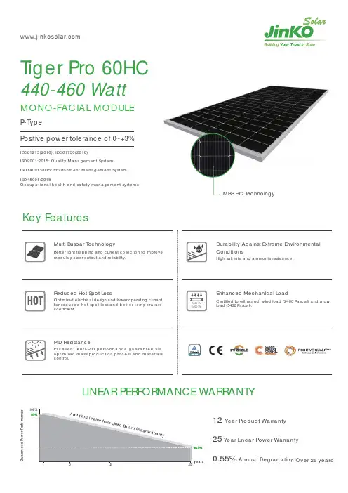
PID ResistanceP-TypeTiger Pro 60HC440-460 WattMBB HC TechnologyMONO-FACIAL MODULEPositive power tolerance of 0~+3%ISO9001:2015: Quality Management System ISO14001:2015: Environment Management System ISO45001:2018Occupational health and safety management systemsIEC61215(2016), IEC61730(2016)Key FeaturesMulti Busbar TechnologyBetter light trapping and current collection to improve module power output and reliability.Reduced Hot Spot LossOptimized electrical design and lower operating current for reduced hot spot loss and better temperature coefficient.Excellent Anti-PID performance guarantee via optimized mass-production process and materials control.Certified to withstand: wind load (2400 Pascal) and snow load (5400 Pascal).Enhanced Mechanical LoadHigh salt mist and ammonia resistance.Durability Against Extreme Environmental Conditions12 Year Produ ct Warrant y25 Year Linea r Power Wa rranty0.55% Annual De gradation Over 25 ye arsLINEAR PERFORMANCE WARRANTY98%100%151225yearsG u a r a n t e e d P o w e r P e r f o r m a n c eA d d it i o n al v a l ue f r o mJ i n k oS o l ar’s l i n ea r w ar r a n ty84.8%HOT2400 Pa 5400 PaCell Type No. of cells Dimensions WeightFront Glass Frame Junction Box Output Cables24.2 kg (53.35 lbs)IP68 RatedIrradiance 1000W/m2AM=1.5Irradiance 800W/m 2AM=1.5NOCT:*STC:Wind Speed 1m/sModule TypeMaximum Power (Pmax) Maximum Power Voltage (Vmp) Maximum Power Current (Imp) Open-circuit Voltage (Voc)Short-circuit Current (Isc)Module Efficiency STC (%)Operating Temperature(℃) Maximum system voltage Maximum series fuse rating Power toleranceTemperature coefficients of Pmax Temperature coefficients of Voc Temperature coefficients of IscNominal operating cell temperature (NOCT)Cell Temperature 25°CAmbient Temperature 20°C( Two pallets = One stack )35pcs/pallets, 70pcs/stack, 840pcs/ 40'HQ ContainerTemperature Dependence ofIsc,Voc,Pmax-50-25025507510020406080100120140160180IscVocPmaxTUV 1×4.0mm(+): 400mm , (-): 200mm or Customized Length3.2mm,Anti-Reflection Coating,High Transmission, Low Iron, Tempered GlassAnodized Aluminium Alloy1903×1134×30mm (74.92×44.65×1.18 inch)Current-Voltage & Power-VoltageCurves (450W)120 (6×20)P type Mono-crystallineNOCT STCNOCT STC NOCT STC JKM440M-60HL4-V JKM445M-60HL4-V JKM450M-60HL4-V JKM440-460M-60HL4-(V)-F1-EN©2020 Jinko Solar Co., Ltd. All rights reserved.Specifications included in this datasheet are subject to change without notice.Length: ±2mmWidth: ±2mm Height: ±1mm Row Pitch: ±2mm-40℃~+85℃1000/1500VDC (IEC)25A 0~+3%-0.35%/℃-0.28%/℃0.048%/℃45±2℃ⅠFrontSideBackC u r r e n t (A )Voltage (V)Cell Temperature (℃)P o w e r (W )N o r m a l i z e d I s c , V o c , P m a x (%)A-A000152025303540452468101275150225375300510450141620.39%440Wp 33.72V 13.05A 41.02V 13.73A327Wp 10.43A 31.39V 38.72V 11.09A20.62%445Wp 33.82V 13.16A 41.10V 13.79A331Wp 10.49A 31.56V 38.79V 11.14ANOCT STC NOCT STC JKM455M-60HL4-V JKM460M-60HL4-V JKM440M-60HL4JKM445M-60HL4JKM450M-60HL4JKM455M-60HL4JKM460M-60HL421.08%455Wp 34.06V 13.36A 41.33V 13.93A339Wp 10.61A 31.91V 39.01V 11.25A21.32%460Wp 34.20V 13.45A 41.48V 14.01A342Wp 10.67A 32.07V 39.15V 11.32A20.85%450Wp 33.91V 13.27A 41.18V 13.85A335Wp 10.55A 31.73V 38.87V 11.19A。
C i r c u i t b r e a k e r sCircuit breakersTeSys GV, GBC ontrol and P rotection C omponentsChapterB60.75g g 1.1g g 1.5375 2.533.5 LR2 K0308GV2LE071.1g g –––––– 2.533.5 LR2 K0308GV2LE071.5g g 1.5g g 3375451 LR2 K0310GV2LE08––– 2.2g g –––451 LR2 K0312GV2LE082.2g g 3501004375 6.378 LR2 K0312GV2LE103g g 410100 5.537510138 LR2 K0314GV2LE144g g 5.510100–––10138 LR2 K0316GV2LE14––––––7.537510138 LRD 14GV2LE14––––––937514170 LRD 16GV2LE165.515507.56751137514170 LR2 K0321GV2LE167.5155096751537518223 LRD 21GV2LE20915401147518.537525327 LRD 22GV2LE2211154015475–––25327 LRD 22GV2LE2215105018.54752237532416LRD 32GV2LE32(1) As % of Icu.g ) > 100 kA.GV2 LE10D F 526144.t i fC i r c u i t b r e a k e r s0.09––––––0.45LRD 03GV2L030.12g g –––0.37g g 0.638LRD 04GV2L040.18g g ––––––0.638LRD 04GV2L04––––––0.55g g 113LRD 05GV2L050.25g g ––––––113LRD 05GV2L05––––––0.75g g 113LRD 06GV2L050.37g g 0.37g g –––113LRD 05GV2L050.55g g 0.55g g 1.1g g 1.622.5LRD 06GV2L06–––0.75g g ––– 1.622.5LRD 06GV2L060.75g g 1.1g g 1.54100 2.533.5LRD 07GV2L07Example: GV3 L32 becomes GV3 L326.(1) As % of Icu. Associated current limiter or fuses, where required. See characteristics page B6/33.g > 100 kA.GV2 L10D F 526145.t i fGV3 L65D F 526146.t i fTeSys GVThermal-magnetic motor circuit breakers GV2 ME0.06gg––––––0.16…0.252.4GV2ME020.09g g––––––0.25…0.405GV2ME030.12 0.18g g g g – –– –– – 0.37 –g–g –0.40…0.638GV2ME040.25gg––– 0.55gg0.63…113GV2ME050.37 0.55 –g g –g g –0.37 0.55 0.75g g g g g g – 0.75 1.1– g g – g g 1…1622.5GV2ME060.75g g1.1gg1.5375 1.6...2.533.5GV2ME071.1 1.5g g g g 1.5 2.2g g g g 2.2 3 3 375 75 2.5 (4)51GV2ME082.2gg350100 43754...6.378GV2ME103 4g g g g 4 5.510 10100 100 5.5 7.5 3 375 756 (10)138GV2ME145.5 –15 –50 –7.5 – 6 –75 – 9 11 3 375 759…14170GV2ME167.5155096751537513…18223GV2ME209154011475 18.537517…23327GV2ME2111154015475 –––20…25327GV2ME22 (3)15105018.54752237524 (32)416GV2ME32Motor circuit breakers from 0.06 to 15 kW / 400 V, with lugsTo order thermal magnetic circuit breakers with connection by lugs, add the digit 6 to the end of reference selected above.Example: GV2 ME08 becomes GV2 ME086.Thermal magnetic circuit breakers GV2 ME with built-in auxiliary contact block With instantaneous auxiliary contact block (composition, see page B6/11):b GV AE1, add suffix AE1TQ to the motor circuit breaker reference selected above. Example: GV2 ME01AE1TQ .b GV AE11, add suffix AE11TQ to the motor circuit breaker reference selected above. Example: GV2 ME01AE11TQ .b GV AN11, add suffix AN11TQ to the motor circuit breaker reference selected above. Example: GV2 ME01AN11TQ .These circuit breakers with built-in contact block are sold in lots of 20 units in a single pack.(1) As % of Icu.(2) The thermal trip setting must be within the range marked on the graduated knob.(3) Maximum rating which can be mounted in enclosures GV2 MC or MP , please consult your Regional Sales Office. g > 100 kA.GV2 ME10D F 526134.t i fC i r c u i t b r e a k e r sTeSys GVTeSys protection componentsThermal-magnetic motor circuit breakers GV2 MEReferences0.06g g ––– 0.16…0.25 2.4GV2ME0230.09g g ––– 0.25…0.405GV2ME0330.120.18g g g g –––0.40…0.638GV2ME0430.250.37g g g g 0.37g g 0.63…113GV2ME0530.370.55g g g g 0.370.550.75g g g g g g 1…1.622.5GV2ME0630.75g g1.1g g 1.6…2.533.5GV2ME0731.11.5g g g g 1.52.2g g g g 2.5…451GV2ME0832.2g g 350100 4…6.378GV2ME10334g g g g 45.510101001006…10138GV2ME1435.515507.5675 9…14170GV2ME1637.515509675 13…18223GV2ME203911151540401147517…23327GV2ME2131115401547520 (25)327GV2ME223Contact blocksDescription Mounting Maximum number Type of contacts Sold in lots of Unitreference Instantaneous auxiliary contactsFront 1N/O + N/C 10GVAE113N/O + N/O 10GVAE203LH side2N/O + N/C 1GVAN113N/O + N/O1GVAN203AccessoryDescriptionApplicationSold in lots of Unitreference Cable end reducerFor connection of conductors from 1 to 1.5 mm 220LA9D99(1) For connection of conductors from 1 to 1.5 mm 2, the use of an LA9 D99 cable end reducer is recommended.(2) Maximum rating which can be mounted in enclosures GV2 MC or MP , please consult your Regional Sales Office (3) The thermal trip setting must be within the range marked on the graduated knob.g > 100 kA.GV2 ME pp 3D F 526135.t i fLA9 D99D F 533898.e p sTeSys GVReferencesTeSys protection componentsThermal-magnetic motor circuit breakersGV2 P, GV3 P and GV3 ME80GV2 P10D F 526137.t i fGV3 P65D F 526139.t i fGV3 P651D F 526140.t i fC i r c u i t b r e a k e r sTeSys GVReferences93610011181001581007.59707010010091150501001001115101010010012…20GV7RS20 2.0109113636100100111518181001001518.58810010015…25GV7RE25 2.0109117070100100111550501001001518.5101010010015…25GV7RS25 2.01018.53610018.522181810010022810025…40GV7RE40 2.01018.57010018.550100221010025…40GV7RS40 2.0102236100301810030810030…50GV7RE50 2.01522701003050100301010030 (50)GV7RS502.01537361004555181810010055810048...80GV7RE80 2.040377010045555050100100551010048...80GV7RS80 2.0404536100–1810075810060...100GV7RE100 2.0404570100–50100751010060...100GV7RS100 2.0405575353510010075903030100100901108810010090 (150)GV7RE1502.020557570701001007590505010010090110101010010090…150GV7RS150 2.02090110353510010011013216030303010010010016020088100100132…220GV7RE220 2.3509011070701001001101321605050501001001001602001010100100132…220GV7RS220 2.350(1) As % of lcu.TeSys protection componentsThermal-magnetic motor circuit breakers GV7 RGV7 RE40D F 526138.t i fGV7 RS220D F 526141.t i f0.12–0.120.180.18–0.370.40…0.6313GV2RT040.090.120.250.370.250.370.370.550.63…122GV2RT050.180.250.370.550.370.550.370.550.750.751.11…1.633GV2RT060.370.750.751.1 1.11.51.6…2.551GV2RT070.550.75 1.11.5 1.51.52.2 2.23 2.5…478GV2RT081.12.22.23344…6.3138GV2RT101.52.234445.5 5.57.56…10200GV2RT142.23 5.55.57.57.59119…14280GV2RT1647.57.5991513…18400GV2RT205.5911111118.517…23400GV2RT21(1) The thermal trip setting must be within the range marked on the graduated knob.GV2 RTD F 526142.t i fC i r c u i t b r e a k e r sblack handle, blue legend plate(1) The thermal trip setting must be within the range marked on the graduated knob.(2) Other accessories such as mounting, cabling and marking accessories are identical to those used for GV2 ME motor circuit breakers, see page B6/13.GV2 RTD F 526142.t i fD F 526340.e p sC i r c u i t b r e a k e r sTeSys GVDescription Mounting Maximum number Type of contacts Sold inlots of Unitreference Instantaneous auxiliary contactsFront (1)1N/O or N/C (2)10GVAE1N/O + N/C 10GVAE11N/O + N/O10GVAE20Side (LH)2N/O + N/C1GVAN11N/O + N/O1GVAN20Fault signalling contact + instantaneous auxiliary contact Side (3) (LH)1N/O (fault)+ N/O1GVAD1010+ N/C1GVAD1001N/C (fault)+ N/O1GVAD0110+ N/C1GVAD0101Short-circuit signalling contactSide (LH)1C/O common point1GVAM11(1 block on RH sideof circuit breaker GV2 ME)50 Hz GVAX11560 Hz GVAX116127 V60 Hz GVAX115220…240 V 50 Hz GVAX22560 Hz GVAX226380…400 V50 Hz GVAX38560 Hz GVAX386415…440 V 50 Hz GVAX415440 V60 Hz GVAX385Add-on contact blocksDescriptionMountingMaximum number Reference Visible isolation block (5)Front (1)1GV2AK00 (6)LimitersAt top(GV2 ME and GV2 P)1GV1L3Independent1LA9LB920(1) Mounting of a GV AE contact block or a GV2 AK00 visible isolation block on GV2 P and GV2 L .(2) Choice of N/C or N/O contact operation, depending on which way round the reversible block is mounted.(3) The GV AD is always mounted next to the circuit breaker.(4) To order an undervoltage trip: replace the dot (p ) in the reference with a U , example: GV AU025. To order a shunt trip: replace the dot (p ) in the reference with an S , example: GV AS025.(5) Visible isolation of the 3 poles upstream of circuit breaker GV2 P and GV2 L .Visible isolation block GV2 AK00 cannot be used with motor circuit breakers GV2 P32 and GV2 L32 (Ith max = 25 A).(6) Ie Max = 32 A.ReferencesTeSys protection componentsThermal-magnetic and magnetic motor circuit breakers GV2 with screw clamp connectionsAdd-on blocks and accessoriesCharacteristics:pages B6/89 and B6/94Dimensions, schemes:pages B6/70 to B6/82LA9LB920D B 126629.e p sC i r c u i t b r e a k e r sTeSys GVTerminal blockfor supply to one or more GV2 G busbar setsConnection from the top1GV1G09Can be fitted with current limiter GV1 L3 (GV2 ME and GV2 P)1GV2G05Cover for terminal block For mounting in modular panels10LA9E07Flexible 3-pole connection for connecting a GV2 to a contactor LC1-D09…D25 Centre distance between mounting rails: 100…120 mm10GV1G02Set of connections upstream/downstream For connecting GV2 ME to a printed circuit board 10GV2GA01“Large Spacing” adapter UL 508 type EFor GV2 P pp H7 (except 32 A)1GV2GH7Clip-in marker holders (supplied with each circuit breaker)For GV2 P , GV2 L, GV2 LE and GV2 RT (8 x 22 mm)100LA9D92ReferencesTeSys protection componentsThermal-magnetic and magnetic motor circuit breakers GV2 with screw clamp connectionsAccessoriesDimensions, schemes:pages B6/70 to B6/82D B 417942.e p sTeSys GVD B 126631.e p sD B 126630.e p sD B 126632.e p s7P B 106297_45.e p sExtended Rotary HandleAllows a circuit breaker or a starter-controller installed in back of an enclosure to be operated from the front of the enclosure.A rotary handle can be black or red/yellow, IP54 or IP65. It includes a function for locking the circuit breaker or the starter in the O (Off) or I (On) position(depending of the type of rotary handle) by means of up to 3 padlocks with a shank diameter of 4 to 8 mm. The extended shaft must be adjusted to use in different size enclosures. The IP54 rotary handle is fixed with a nut (Ø22) to make easierthe assembling. The new Laser Square tool brings the accuracy to align the circuit breaker and the rotary handle.device(padlocks not included)ReferencesTeSys protection componentsThermal-magnetic and magnetic motor circuit breakers GV2 with screw clamp connectionsC i r c u i t b r e a k e r sTeSys GVDescriptionMounting Maximum number Type of contacts Sold inlots of Unitreference Instantaneous auxiliary contactsFront1N/O or N/C (1)10GVAE1N/O + N/C 10GVAE11 (2)N/O + N/O10GVAE20 (2)Side (LH)2N/O + N/C1GVAN11 (2)N/O + N/O1GVAN20 (2)Fault signalling contact + instantaneous auxiliary contactFront 1N/O (fault)+ N/O1GVAED101 (2)N/O (fault)+ N/C1GVAED011 (2)Side (3) (LH)1N/O (fault)+ N/O1GVAD1010+ N/C1GVAD1001N/C (fault)+ N/O1GVAD0110+ N/C1GVAD0101Short-circuit signalling contact Side (LH)1C/O common point 1GVAM11(4)MountingVoltage ReferenceSide(1 block on RH side of circuit breaker)24 V 50 Hz GVA p 02560 Hz GVA p 02648 V 50 Hz GVA p 05560 Hz GVA p 05610050 Hz GVA p 107100…110 V 60 Hz GVA p 107110…115 V 50 Hz GVA p 11560 Hz GVA p 116120…127 V 50 Hz GVA p 125127 V 60 Hz GVA p 115200 V50 Hz GVA p 207200…220 V 60 Hz GVA p 207220…240 V 50 Hz GVA p 22560 Hz GVA p 226380…400 V 50 Hz GVA p 38560 Hz GVA p 386415…440 V 50 Hz GVA p 415415 V 60 Hz GVA p 416440 V 60 Hz GVA p 385480 V 60 Hz GVA p 415500 V 50 Hz GVA p 505600 V60 HzGVA p 505AccessoriesDescription Reference Sets of 3-pole 115 A busbars Pitch: 64 mm2 tap-off GV3 P pp and GV3 L pp GV3G2643 tap-off GV3 P pp and GV3 L pp GV3G364Cover “Large Spacing” UL 508 type E (Only one cover required on supply side)GV3 P ppGV3G66(1) Choice of N/C or N/O contact operation, depending on which way round the reversible block is mounted.(2) Contact blocks available in version with spring terminal connections. Add a figure 3 at the end of the references selected above. Example: GV AED101 becomes GV AED1013.(3) The GV AD pp is always mounted next to the circuit breaker.(4) To order an undervoltage trip: replace the dot (p ) in the reference with a U , example: GV AU025. To order a shunt trip: replace the dot (p ) in the reference with an S , example: GV AS025.Add-on blocks and accessoriesGV3 G66D F 537424.e p sTeSys GVD B 126637.e p sD B 126636.e p sD B 126632.e p s7P B 106297_45.e p sExtended Rotary HandleAllows a circuit breaker or a starter-controller installed in back of an enclosure to be operated from the front of the enclosure.A rotary handle can be black or red/yellow, IP54 or IP65. It includes a function for locking the circuit breaker or the starter in the O (Off) or I (On) position(depending of the type of rotary handle) by means of up to 3 padlocks with a shank diameter of 4 to 8 mm. The extended shaft must be adjusted to use in different size enclosures. The IP54 rotary handle is fixed with a nut (Ø22) to make easierthe assembling. The new Laser Square tool brings the accurency to align the circuit breaker and the rotary handle.For English 10-GVAPSEN For German 10-GVAPSDE For Spanish10-GVAPSES For Chinese 10-GVAPSCN For Portuguese 10-GVAPSPT For Russian 10-GVAPSRU For Italian10-GVAPSITD F 526342.e p sB6/21C i r c u i t b r e a k e r sTeSys GVfor locking the Start button (on open-mounted product)using up to 3 padlocks(padlocks to be ordered separately)External operator for mounting on enclosure door.Red Ø40 knob on yellow plate, padlockable in position O (with up to 3 padlocks). Door locked when knob in position I, and when knob padlocked in position O.GK3AP03(1) 1 voltage trip OR 1 fault signalling contact to be fitted inside the motor circuit breaker.Other versions24 to 690 V, 50 or 60 Hz voltage trips for circuit breakers GV3 ME80.Please consult your Regional Sales Office.ReferencesTeSys protection componentsMotor circuit breakers GV3 ME80 and GK3 EF80Add-on blocks and accessoriesCharacteristics:pages B6/89 and B6/92Dimensions:page B6/47B6/22D F 526344.e p sB6/23C i r c u i t b r e a k e r sTeSys GVThese allow remote indication of the circuit breaker contact states. They can be used for signalling, electrical locking, relaying, etc. They are available in two versions: standard and low level. They include a terminal block and the auxiliary circuits leave the circuit breaker through a hole provided for this purpose.They perform the following functions, depending on where they are located in the circuit breaker:Low levelGV7AB11Fault discrimination devicesThese make it possible to:b either differentiate a thermal fault from a magnetic fault,b or open the contactor only in the event of a thermal fault.VoltageReference a 24...48 and c 24…72 V GV7AD111 (1)z 110…240 VGV7AD112 (1)Electric tripsThese allow the circuit breaker to be tripped via an electrical control signal.b Undervoltage trip GV7 AUv Trips the circuit breaker when the control voltage drops below the tripping threshold, which is between 0.35 and 0.7 times the rated voltage.v Circuit breaker closing is only possible if the voltage exceeds 0.85 times the rated voltage. Circuit breaker tripping by a GV7 AU trip meets the requirements of IEC 60947-2.b Shunt trip GV7 ASTrips the circuit breaker when the control voltage rises above 0.7 times the rated voltage.b Operation (GV7 AU or GV7 AS)v When the circuit breaker has been tripped by a GV7 AU or AS, it must be reset either locally or by remote control. (For remote control, please consult your Regional Sales Office).v Tripping has priority over manual closing: if a tripping instruction is present, manual action does not result in closing, even temporarily, of the contacts.v Durability: 50 % of the mechanical durability of the circuit breaker.TypeVoltageReference Undervoltage trip48 V, 50/60 HzGV7AU055 (1)110…130 V, 50/60 Hz GV7AU107 (1)200…240 V, 50/60 Hz GV7AU207 (1)380…440 V, 50/60 Hz GV7AU387 (1)525 V, 50 HzGV7AU525 (1)Shunt trip48 V, 50/60 HzGV7AS055 (1)110…130 V, 50/60 Hz GV7AS107 (1)200…240 V, 50/60 Hz GV7AS207 (1)380…440 V, 50/60 Hz GV7AS387 (1)525 V, 50 HzGV7AS525 (1)(1) For mounting of a GV7 AD or a GV7 AU or AS.ReferencesTeSys protection componentsThermal-magnetic motor circuit breakers GV7 R with screw clamp connectionsAdd-on blocks and accessoriesCharacteristics:pages B6/51, B6/52 and B6/56Dimensions:pages B6/79 to B6/81Schemes:page B6/83B6/24B6/25C i r c u i t b r e a k e r sTeSys GVDescription ApplicationFor use on contactors Sold in lots of Unitreference Clip-on connectors for GV7 RUp to 150 A, 1.5…95 mm 2–3GV7AC021Up to 220 A, 1.5…185 mm 2–3GV7AC022Spreader 3-pole (1)To increase the pitch to 45 mm–1GV7AC03Terminal shields IP 405 (1)Supplied with sealing accessory–1GV7AC01Phase barriersSafety accessories used when fitting of shields is impossible –2GV7AC04Insulating screens Ensure insulation between the connections and the backplate –2GV7AC05Kits for combination with contactor (2)Allowing link between thecircuit breaker and the contactor. The cover provides protection against direct finger contactLC1 F115…F1851GV7AC06LC1 F225 and F2651GV7AC07LC1 D115 and D1501GV7AC08Replaces the circuit breaker front cover; secured by screws. It includes a device for locking the circuit breaker in the O (Off) position by means of up to 3 padlocks with a shank diameter of 5 to 8 mm (padlocks not included). A conversion accessory allows the direct rotary handle to be mounted on the enclosure door. In this case, the door cannot be opened if the circuit breaker is in the “ON” position. Circuit breaker closing is inhibited if the enclosure door is open.Description TypeDegree of protection Reference Direct rotary handleBlack handle, black legend plate IP 40GV7AP03Red handle, yellow legend plateIP 40GV7AP04Adapter plate (3)Four mounting direct rotary handle on enclosure doorIP 43GV7AP05Allows a circuit breaker installed in the back of an enclosure to be operated from the front of the enclosure. It comprises:b a unit which screws onto the front cover of the circuit breaker,b an assembly (handle and front plate) to be fitted on the enclosure door,b an extension shaft which must be adjusted (distance between the mounting surface and the door: 185 mm minimum, 600 mm maximum). It includes a device for locking the circuit breaker in the O (Off) position by means of up to 3 padlocks with a shank diameter of 5 to 8 mm (padlocks not included). This prevents the enclosure door from being opened.DescriptionTypeDegree of protection Reference Extended rotary handleBlack handle, black legend plate IP 55GV7AP01Red handle, yellow legend plateIP 55GV7AP02Allows circuit breakers not fitted with a rotary handle to be locked in the O (Off) position by means of up to 3 padlocks with a shank diameter of 5 to 8 mm (padlocks not included).Description ApplicationReference Locking deviceFor circuit breaker not fitted with a rotary handleGV7V01(1) Terminal shields cannot be used together with spreaders.(2) The kit comprises links, a protective shield and a depth adjustable metal bracket for the breaker.(3) This conversion accessory makes it impossible to open the door if the device is closed and prevents the device from being closed if the door is open.ReferencesTeSys protection componentsThermal-magnetic motor circuit breakers GV7 R with screw clamp connectionsAccessoriesGV7 AC07D F 537429.e p sGV7 AC08D F 537428.e p sDimensions:pages B6/79 to B6/81B6/260.5 6.63GB2DB051143GB2DB062263GB2DB073403GB2DB084503GB2DB095663GB2DB106833GB2DB1281083GB2DB14101383GB2DB16121653GB2DB20162203GB2DB21202703GB2DB22(1) Conforming to IEC 60947-1.GB2 CBppD F 526243.t i fGB2 CD ppD F 526244.t i fGB2 DBppD F 526245.t i fPresentation, selection :page B6/84Characteristics :pages B6/85 to B6/87Dimensions :page B6/88Schemes :page B6/88B6/27C i r c u i t b r e a k e r s(1) Conforming to IEC 60947-1.Accessories for circuit breakers GB2-CB, DB and CSDescriptionSold in lots of Unitreference Busbar set for supply to 10 GB2 DB or20 GB2 CB or GB2 CS with 2 connectors1GB2G210Supply connector 10GB2G01GB2 CS ppD F 526246.t i fPresentation, selection :page B6/84Characteristics :pages B6/85 to B6/87Dimensions :page B6/88Schemes :page B6/88B6/28B6/29B6/30TeSys GVCharacteristicsTeSys protection componentsMagnetic motor circuit breakers GV2 LE and GV2 LReferences:pages B6/2 and B6/3Dimensions:pages B6/43 to B6/47Schemes:page B6/48add-on contact blocks. Side by side mounting is possible up to 40 °C.(2) When mounting on a vertical rail, fit a stop to prevent any slippage.(1) As % of Icu.Average operating times at 20 °C related to multiples of the setting currentD F 534092.e p s1 3 poles from cold state2 2 poles from cold state3 3 poles from hot stateDynamic stressI peak = f (prospective Isc) at 1.05 Ue = 435 VD F 534093.e p s1 Maximum peak current2 32 A3 25 A4 18 A5 14 A6 10 A7 6.3 A8 4 A9 2.5 A 10 1.6 A11 Limit of rated ultimate breaking capacity on short-circuit of GV2 LE (14, 18, 23 and 25 A ratings).Dynamic stressI peak = f (prospective Isc) at 1.05 Ue = 435 VD F 534094.e p s1 Maximum peak current2 32 A3 25 A4 18 A5 14 A6 10 A7 6.3 A8 4 A9 2.5 A 10 1.6 A11 Limit of rated ultimate breaking capacity on short-circuit of GV2 LE (14, 18, 23 and 25 A ratings).Thermal limit in kA 2s in the magnetic operating zone Sum of I 2dt = f (prospective Isc) at 1.05 Ue = 435 V22Prospective Isc (kA)D F 534095.e p s1 32 A 2 25 A3 18 A4 14 A5 10 A6 6.3 A7 4 A8 2.5 A9 1.6 AThermal limit in kA 2s in the magnetic operating zone Sum of I 2dt = f (prospective Isc) at 1.05 Ue = 435 V22D F 534096.e p s1 25 A and 32 A 2 18 A3 14 A 4 10 A5 6.3 A6 4 A7 2.5 A8 1.6 AThermal limit in kA 2s in the magnetic operating zone Sum of I 2dt = f (prospective Isc) at 1.05 Ue = 435 V22D F 534097.e p s1 32 A (GV2 LE32)2 25 A and 32 A (GV2 L32)3 18 A4 14 A5 10 A6 6.3 A7 4 A8 2.5 A9 1.6 A10 Limit of rated ultimate breaking capacity on short-circuit of GV2 LE (14, 18, 23 and 25 A ratings).Average operating time at 20 °C without prior current flowx the setting current (Ir)D F 534098.e p s1 3 poles from cold state2 2 poles from cold state3 3 poles from hot stateA Thermal overload relay protection zoneB GV3 L protection zoneDynamic stressI peak = f (prospective Isc) at 1.05 Ue = 435 VProspective Isc (kA)D B 418280.e p s1 Maximum peak current2 GV3 L653 GV3 L504 GV3 L405 GV3 L326 GV3 L25Thermal limit in A 2sSum of I 2dt = f (prospective Isc) at 1.05 Ue = 435 V2Prospective Isc (kA)D B 418279.e p s1 GV3 L652 GV3 L503 GV3 L404 GV3 L325 GV3 L25TeSys GVDimensions, mountingD F 537440.e p sD F 537441.e p sD F 537444.e p sTeSys protection componentsMagnetic motor circuit breakers GV2 L and GV2 LETeSys GVDimensions, mounting TeSys protection componentsMagnetic motor circuit breakers GV2 L and GV2 LED B 127415.e p sD B 127414.e p sa b Mini Maxi Mini Maxi GV2 APN pp140250GV2 APN pp + GV APH02151250GV2 APN pp + GV APK11250434--GV2 APN pp + GV APH02 + GV APK11--250445TeSys GVDimensions,mounting Sets of busbars GV2 G445, GV2 G454, GV2 G472, with terminal block GV2 G05D F 537451.e p sGV2 G445224269314359GV2 G454260314368422GV2 G472332404476548D F 537452.e p sD F 537454.e p sGV2 G345 (3 x 45 mm)134GV2 G354 (3 x 54 mm)152TeSys protection componentsMagnetic motor circuit breakers GV2 L and GV2 LED F 537480.e psD F 537435.e p sD F 510637.e p sD F 510638.e p sD B 127416.e p sD B 127417.e p sa b Mini Maxi Mini Maxi GV3 APN pp189300--GV3 APN pp + GV APK12300481GV3 APN pp + GV APH03--200300GV3 APN pp + GV APH03 + GV APK12--300492TeSys GVSchemesTeSys protection componentsMagnetic motor circuit breakers GV2 L, GV2 LE, GV3 LD F 537474.e p sD F 537475.e p sD F 537476.e p sGV2 ME, GV2 P , GV3 ME, GV3 P and GV7 R motor circuit breakers are 3-pole thermal-magnetic circuit breakers specifically designed for the control and protection of motors , conforming to standards IEC 60947-2 and IEC 60947-4-1.Connection GV2GV2 ME and GV2 P circuit breakers are designed for connection by screw clamp terminals.Circuit breaker GV2 ME can be supplied with lugs or spring terminal connections.Spring terminal connections ensure secure, permanent and durable clamping that is resistant to harsh environments, vibration and impact and are even more effective when conductors without cable ends are used. Each connection can take two independent conductors.GV3GV3 circuit breakers feature connection by BTR screws (hexagon socket head), tightened using a n° 4 Allen key.This type of connection uses the Ever Link ® system with creep compensation (1) (Schneider Electric patent).This technique makes it possible to achieve accurate and durable tightening torque, in order to avoid cable creep.GV3 circuit breakers are also available with connection by lugs. This type of connection meets the requirements of certain Asian markets and is suitable for applications subject to strong vibration, such as railway transport.GV7GV7 circuit breakers: with connection by screw clamp terminals (for bars and lugs) and by clip-on connectors.OperationControl is manual and local when the motor circuit breaker is used on its own.Control is automatic and remote when it is associated with a contactor.GV2 ME and GV3 ME80Pushbutton control.Energisation is controlled manually by operating the Start button “I” 1.De-energisation is controlled manually by operating the Stop button “O” 2, or automatically by the thermal-magnetic protection elements or by a voltage trip attachment.GV2 P , GV3 P and GV7 Rb Control by rotary knob: for GV2 P and GV3 P b Control by rocker lever: for GV7 R.Energisation is controlled manually by moving the knob or rocker lever to position “I” 1.De-energisation is controlled manually by moving the knob or rocker lever to position “O” 2.De-energisation due to a fault automatically places the knob or rocker lever in the “Trip” position 3.Re-energisation is possible only after having returned the knob or rocker lever to position “O”.(1) Creep: normal crushing phenomenon of copper conductors, that is accentuated over time.GV2 MEwith screw clamp terminals124D F 526134.t i fGV2 MEwith spring terminals connections124D F 526135.t i fGV3 P1324D F 526136.t ifGV2 P1342D F 526137.t i fGV7 R132D F 526138.t i f。
产品规格书SPECIFICATION客户Customer 客户型号Customer Model项目名称Project Name JZ-JY-0011文件编号Document NO受控版本Controlled Revision 实施日期Issued Date编制Registered 审核Checked审核Checked 审核Checked批准Approved 批准Approved五、连线示意图及连接步骤Linking diagram and connecting steps1、充电接线方式the charging connecting method:充电器负极接P-;P-connects to the cathode of the charging;充电器正极接B+;B+ connects to the Anode of the charging;2、放电接线方式the discharging connecting method:负载负极接P-;P- pads connects to the cathode of the loader;负载正极接B+。
B+ connects to the anode of the charging.3、注意事项notes:将电池和本保护板组合好以后,初次上电时,如果发现无电压输出,请用专用充电器充电激活。
若仍有异常,请与厂家联系。
After assembling the battery and the protection board, if there is no voltage output when your first power on, please charge the battery with the special charger and it will work normal.If there is still abnormal, please contact us.六、使用和组装的注意事项The notes of using and assembling1、焊接电池引线时,一定要小心,不可接错或反接。
※本文件之著作权属 XXX 电池科技(深圳)有限公司,非经允许不得翻印※
※本文件之著作权属 XXX 电池科技(深圳)有限公司,非经允许不得翻印※
※本文件之著作权属 XXX 电池科技(深圳)有限公司,非经允许不得翻印※
※本文件之著作权属 XXX 电池科技(深圳)有限公司,非经允许不得翻印※
※
本 文 件 之 著 作 权 属 XXX 电 池 科 技 (深 圳) 有 限 公 司 ,
非 经 允 许 不 得 翻 印 ※
本 文 件 之 著
作 权 属 XXX 电 池 科 技 (深 圳) 有 限 公 司 , 非 经 允 许 不 得 翻 印 ※
本文件之著作权属 XXX 电池科技(深圳)有限公司,非经允许不得翻印※
本文件之著作权属 XXX 电池科技(深圳)有限公司,非经允许不得翻印※
※本文件之著作权属 XXX 电池科技(深圳)有限公司,非经允许不得翻印※
※本文件之著作权属 XXX 电池科技(深圳)有限公司,非经允许不得翻印※
※本文件之著作权属 XXX 电池科技(深圳)有限公司,非经允许不得翻印※
※本文件之著作权属 XXX 电池科技(深圳)有限公司,非经允许不得翻印※
※本文件之著作权属 XXX 电池科技(深圳)有限公司,非经允许不得翻印※
※本文件之著作权属 XXX 电池科技(深圳)有限公司,非经允许不得翻印※。
电量平衡保护IC堆积技术的多化合物锂动力电池保护板 产品特点●采用A级保护集成电路IC 日本精工S-8209A方案●IC自带电量平衡功能,且平衡电路简单可靠●过充,过放动作信号采用高可靠性的硬件通迅●高耐压,低导通内阻TO-220封装功率MOSFET●温漂极小,精度为1%高功率2512封装检测电阻●94V-0高防火等级双面玻璃纤维板●最大工作电流75A,持续额定电流30A●极低的耗电,静态待机耗电7uA.工作耗电15uA均衡启动时耗电60mA+7uA(单个电池)●整体PCBA放电通态内阻<50mΩ,充电通态内阻<65mΩ●具有典型的电压侦测方式的过充电保护,过放电保护,过电流保护,短路保护●典型的温度保护功能(75度)●支持20、21、22、23、24、25、26节多化合物锂动力电池的直接串联组合●PCBA板面采用高抗腐蚀性,高耐渗水性,高阻抗ESD的三防漆刷涂产品应用●移动电源或测试设备电源 ●汽车______________________________________________________________________________________ 产品资料,版权所有,武汉智立恒通电子技术有限公司具有最终解释权!产品说明CNL-EP068是一款专门针对汽车后备电源而开发的一款集成IC技术的多化合物锂动力电池保护板,具有过充电保护功能,过放电保护功能,过电流保护功能,温度保护功能,充电电量平衡管理功能。
具有工作电流的高承受能力,但是无论是放电还是充电通路的通态内阻都相当低,保证了在整个工作运行过程中的温度安全。
均衡管理电路在充电末端能对多化合物锂动力电池进行单组电压侦测,同时在均衡点启动耗能式电路对不平衡性电池进行放电耗能,辅助促使电池小电流放电,尽可能的让电池的电压趋于一致。
而充电和放电保护功能均能使电池在一个特定的安全范围内工作。
过电流和短路保护功能当然更能使得用户在非意愿条件下的非法工作更快切断电路而保护当事人或当事物,让人或物不至于受损。
Eaton JGH310032GEaton Series G electronic molded case circuit breaker, JG-frame, JG, Digitrip 310 RMS, Electronic LSI trip, Three-pole, 100A, 600 Vac, 250 Vdc, 100 kAIC at 240 Vac, 65 kAIC at 480 Vac, 25 kAIC at 600 Vac, Line and load, 50/60 HzGeneral specificationsEaton Series G electronic molded case circuit breakerJGH310032G 7821160180863.44 in 7 in4.13 in 6.5 lb Eaton Selling Policy 25-000, one (1) year from the date of installation of theProduct or eighteen (18) months from thedate of shipment of the Product,whichever occurs first.CE Marked UL ListedIEC RatedCSA CertifiedProduct NameCatalog NumberUPCProduct Length/Depth Product Height Product Width Product Weight WarrantyCompliancesCertificationsSeries G25 kAIC at 600 Vac 100 kAIC at 240 Vac 65 kAIC at 480 VacComplete breakerJGJG50/60 HzComplete breakerLine and load600 Vac, 250 Vdc100 AElectronic LSIThree-pole Application of Multi-Wire Terminals for Molded Case Circuit Breakers Application of Tap Rules to Molded Case Breaker TerminalsStrandAble terminals product aidComprehensive circuit protection for control panel applicationsCircuit breaker motor operators product aidMotor protection circuit breakers product aidMulti-wire lugs product aidSeries G MCCB quick selectorCurrent limiting molded case circuit breaker module for series G, JG and CLCurrent limiting molded case circuit breaker module product aidPower metering and monitoring with Modbus RTU product aidMolded case circuit breakers providing higher levels of selective coordination product aidHigh performance operating handles for Series G circuit breakers product aidPlug-in adapters for molded case circuit breakers product aidBreaker service centersJ-Frame 310+ and L-Frame 310+ Molded-case circuit breakersMolded case circuit breakers catalogEaton's Volume 4—Circuit ProtectionAB DE-ION CIRCUIT BREAKER TYPE JG BRKR JG CURR LIMITER 3 POLE OUTLINEJG-frame Molded Case Circuit Breaker DrawingInstallation Instructions for Series G J-Frame Circuit BreakersEaton Specification Sheet - JGH310032GMOEM MCCB product selection guideSeries G, J-frame Time Current CurveNG and ND-Frame molded case circuit breakersSeriesInterrupt ratingTypeFrameCircuit breaker type Frequency ratingCircuit breaker frame type TerminalsVoltage rating Amperage RatingTrip TypeNumber of poles Application notesBrochuresCatalogsDrawingsInstallation instructions Specifications and datasheetsEaton Corporation plc Eaton House30 Pembroke Road Dublin 4, Ireland © 2023 Eaton. All Rights Reserved. Eaton is a registered trademark.All other trademarks areproperty of their respectiveowners./socialmedia。
密级
阶段标记
页数13 原材料技术条件及零部件规格书
名称主板- E02158
编号LSH314.101CT04
拟制
审核
会签
标准化
批准
天津力神电池股份有限公司
1目的
为公司提供原材料技术条件,确保原材料质量处于受控状态,满足生产要求。
2适用范围
适用于316-PP505690-4S5P-PCM型锂离子电池项目,可作为采购进货检验依据。
3技术条件及相关内容
3.1产品简述:
3.1.1名称:E02158
3.1.2BOM:001.19.0000483000
3.2技术要求(@25 ºC)
3.2.1过充保护电压:
4.275V±0.025V
3.2.2过充恢复电压:
4.075V±0.050V
3.2.3过放保护电压: 2.30V ± 0.080V
3.2.4过放恢复电压: 2.70V ± 0.100V
3.2.5过流保护电流:15.5A +/3A(电芯1
4.4V)
3.2.6短路保护功能:OK
3.2.7 均衡起始电压:
4.18V±0.025V
3.3.8 工作温度:-45℃~55℃
3.3.9 存储温度:-40℃~85℃
3.3元器件布件图:
底层
无底层布件
3.4焊盘定义:
顶层
无底层焊盘
3.5机械尺寸:
所有器件符合工业级标准(工作温度范围达-40℃至+85℃):
3.7印制板线路图
底层:
3.8 DS2788文件烧写
3.8.1 DS2788烧写接口如下:
其中:DQ为DS2788通信总线,GND为数据地线。
3.8.2 DS2788基本参数烧写
3.8. 2.1 DS2788基本参数初步烧写。
单击File,选择Flod,该文件为.tex格式,该格式文件明如下TBP316-1_2788_GJ.txt,"11085","11085","11317","11412","11500", "312","305","298","52","34", "29","29","29","18","0", "4.1968","600.0","2.9085","480",
"5.00","1.02637","1.11426","61","11400.00",
"0.3126","00h","-0.3126","20 C","10 C"
单击Write$copy键,进行基本参数烧写。
(注意检流电阻为:5.00mΩ;,电压较准参数为(参数值0.99~1.15);电流校准参数(参数值0.99~1.05)
3.8.2.2 DS2788主要参数校准。
修正电压较准参数(参数值在0.99~1.15之间),并在主界面读取软件电压测量值,使得软件测量电压与实际测量电压压差不超过50mV;
修正电流校准参数(参数值在0.99~1.05之间)。
3.8.3 DS2788老化系数烧写
单击Write和Done键进行老化系数烧写,老化系数设置为98%(烧写后老化系数有略微改变,但变化在97%~98%之间)。
3.8.4 通信地址烧写
寄存器相对地址和相应参数烧写如下
a、额定容量:10000mAh,对应十六进制为2710h,
其中低位地址20h:27h,高位地址21h:10h;
b、节数:4串,对应十六进制为04h,地址为2Ch,
单击Write和Done键进行通信地址烧写。
3.9 单片机ATmega48烧写
3.9.1 AVR并行ISP 烧写器接口和保护板烧写接口如下:3.9.1.1 AVR并行ISP 烧写器接口
3.9.1.2 保护板上单片机ATmega48烧接口如下
3.9.2 烧写方法(AVR studio4 烧写界面)
3.9.2.1 熔丝配置
a. 如图选择BOOLEVEL=110
b. 如图选择默认振荡频率(内部晶振8M),CKSEL=0010,SUT=10
c. 内部晶振频率分频设置:不分频
熔丝配置并烧写完成后界面如下
3.9.2.2 烧写文件写入
a、器件选择:ATmega48
b、烧写模式:ISP mode
c、Flash路径设置:
3.9.2.3 烧写文件
烧写文件为.hex格式,该格式文件如下:TBP316_A_RET_2788.hex 3.10 剩余相对容量修正烧写,测试液晶显示功能
单击Write和Done键进行剩余容量烧写,剩余容量初次烧写为7000mAh,此时液晶显示应为3格。
4 检验项目及检验方法
4.1 目测检查保护板没有弯曲变形,表面洁净,无腐蚀,无异物。
4.2 目测检查保护板上的器件位置,应与3.3条中的元器件布件图相符。
4.3 利用游标卡尺测量保护板关键机械尺寸(*标注),应与3.4相符。
4.4 利用保护板测试仪测试保护板的电气性能,应与3.2相符。
4.5 利用专用烧写工具烧写测试保护板液晶显示和通信功能,应符合3.8、3.9、3.10的要求。
5 存储
原材料应密闭包装,避免潮湿和化学气氛。
6运输
6.1 包装规格要求
防静电包装。
6.2 运输要求
应防止碰撞、防破损。
7修订历史记录。