GM-110BT70(85)(说明书)
- 格式:pdf
- 大小:9.88 MB
- 文档页数:37
Call point – BGDISCLAIMER OF WARRANTIES AND LIMITATION OF LIABILITYThe information, recommendations, descriptions and safety notations in this document are based on Eaton Corporation’s (“Eaton”) experience and judgment and may not cover all contingencies. If further information is required, an Eaton sales office should be consulted. Sale of the product shown in this literature is subject to the terms and conditions outlined in appropriate Eaton selling policies or other contractual agreement between Eaton and the purchaser.THERE ARE NO UNDERSTANDINGS, AGREEMENTS, WARRANTIES, EXPRESSED OR IMPLIED, INCLUDING WARRANTIES OF FITNESS FOR A PARTICULAR PURPOSE OR MERCHANTABILITY, OTHER THAN THOSE SPECIFICALL Y SET OUT IN ANY EXISTING CONTRACT BETWEEN THE PARTIES. ANY SUCH CONTRACT STATES THE ENTIRE OBLIGATION OF EATON. THE CONTENTS OF THIS DOCUMENT SHALL NOT BECOME PART OF OR MODIFY ANY CONTRACT BETWEEN THE PARTIES.In no event will Eaton be responsible to the purchaser or user in contract, in tort (including negligence), strict liability or other-wise for any special, indirect, incidental or consequential damage or loss whatsoever, including but not limited to damage or loss of use of equipment, plant or power system, cost of capital, loss of power, additional expenses in the use of existing power facilities, or claims against the purchaser or user by its customers resulting from the use of the information, recommendations and descriptions contained herein. The information contained in this manual is subject to change without notice.ii Call point – BG TM110 Issue G October 2020 Call point – BGEnglish Contents1. INTRODUCTION (1)2. INSTALLATION (1)General (1)Cable termination (1)3. OPERATION (2)4. MAINTENANCE (2)5. CERTIFICATION/APPROVALS (2)6. CERTIFIED TEMPERATURE (2)7. FUNCTIONAL SAFETY (2)Introduction (2)Assessment of functional safety (2)Conditions of safe use (3)iiiCall point – BG TM110 Issue G October 2020 iv Call point – BG TM110 Issue G October 2020 Call point – BGEnglish1. IntroductionThese fire alarm call point units have been designed for use in harsh environmental conditions.2. InstallationGeneralWhen installing and operating explosion-protected electrical equipment, requirements for selection, installation and operation should be referred to eg. IEC 60079-14 worldwide and the ‘National Electrical Code’ in North America. Additional national and/or local requirements may apply. Ensure that all nuts, bolts and fixings are secure.Ensure that only the correct UL listed stopping plugs are used to blank off unused gland entry points and that the NEMA/IP rating of the unit is maintained.The BG is mounted via 4 x ø 0.24” (6mm) fixing holes in the base. The cover assembly must be removed to gain access to the fixing holes.The fixing holes have been designed to accept an M5 caphead screw or bolt. MEDC recommend the use of stainless steel screws.Cable terminationUnscrew the 4 off screws holding the cover assembly to the base and pull away from the base. Remove to gain access to the interior of the base.Cable termination should be in accordance with specifications applying to the application. MEDC recommend that all cables and cores should be fully identified.Ensure that only correct UL Listed cable glands are used and that the assembly is shrouded and correctly earthed. All cable glands should be of an equivalent NEMA/IP rating to that of the call point and integrated with the unit such that this rating is maintained.The internal earth terminal (where fitted), must be usedfor the equipment grounding connection and the external terminal is for a supplementary bonding connection where local codes or authorities permit or require such a connection. Once termination is complete, carefully push the cover assembly back onto the base, avoiding damage to the mating surfaces. Tighten the 4 off screws in the cover assembly evenly. To maintain the IP rating of the unit, the recommended torque on the cover screws is between 22.5 - 26.5 lbf-in (2.5 - 3.0Nm).WARNING: EXPLOSION HAZARD – Do not disconnect equipment unless power has been removed or the area is known to be non-hazardous.WARNING: EXPLOSION HAZARD – Substitution of any component may impair suitability for Class 1, Division 2. AVERTISSEMENT: RISQUE D’EXPLOSION – Ne pasdébrancher l’équipement à moins que l’alimentation aitété coupée ou que la zone soit connue comme étantnon dangereuse.AVERTISSEMENT: RISQUE D’EXPLOSION – La substitution d’un quelconque composant peut affecter la conformité selon la classe 1, division 2.1 Call point – BG TM110 Issue G October 2020 Call point – BGEnglish3. OperationThe call point is operated by breaking the glass. Due to the design of the unit, there is no need to use a hammer as the operator is protected from the broken glass by a transparent vinyl sheet.The glass, once used, must be replaced for subsequent operations. Remove the small cover held in place by the 2 off slotted screws. Take out the glass carefully and discard. Remember to check for loose fragments. Place a new glass into the unit and replace the cover.Testing the unit can be performed by inserting the test key provided into the hole situated on the bottom-right hand side of the glass cover. Engage the key into thetest cam and turn in a clockwise direction (60° approx.). This will simulate the glass breaking. Return the key to it’s initial position to reset.MEDC does not recommend forcing the test key further than 80° clockwise or 0° anti-clockwise as this may lead to premature failure of the test cam.4. MaintenanceDuring the working life of the call point, little or no maintenance is required. However, if abnormal or unusual environmental conditions occur due to plant damage or accident etc., then visual inspection is recommended.If a fault should occur, it is recommended that the unit be returned to MEDC for repair. All parts are replaceable.If you have acquired a significant quantity of units, itis recommended that spares are also made available. Please discuss your requirements with the Technical Sales Engineers at MEDC.5. Certification/approvalsPlease refer to marking on the unit for specificapproval details.• U L listed for use in USA (USL) and Canada (CNL)Class 1, Division 2, Groups A, B, C & D.• Standards UL38.UL50.ANSI/ISA12.12.01.CSA-C22.2No.14.• Suitable for hazardous location fire-alarm applications. 6. Certified temperature–25°C to +55°C–13°F to +131°F7. Functional safetyIntroductionThe BG Call Point has been designed for use in potentially explosive atmospheres and harsh environmental conditions. The glass reinforced polyester enclosures are suitable for use offshore or onshore, where light weight combined with corrosion resistance is required.The function of the BG is to raise an alarm manually once verification of a fire or emergency condition exists, by breaking the Glass.The BG Break glass Unit is configured with either a single series Resistor (R1) or an R1 and end of line resistor known as R2. No Current passes through R1 in either configuration until the glass has been broken and the switch contacts have closed. Upon closure of the switch the current is then sent through R1 and hence changes the resistive value in the circuit which triggers the alarm. The R2 resistor always has a current flowing through which provides the reference resistive value for the circuit. The circuit can diagnose an open circuit failure in R1 without having to trigger the system via a continuity check which is a form of diagnostics for determiningif an R1 resistor has failed Open Circuit. This form of diagnostics does however require a proof test to be conducted in order to identify the failure and depending on the set up of the system the defective Resistor may not be easily traceable if there are several BG break glass Units in the system. The end of line resistor R2 is used for the purpose of detecting an open or short circuit in the supply conductors.The safety function of the Call Point is to raise the alarm when the Glass is BrokenUnder No fault (Normal) Operating conditions the BG Break Glass Unit will raise the alarm upon operating the switch via breaking the glass.Under fault conditions the failure mode of the Break Glass is a failure to raise the alarm. For the failure rate associated with this failure mode please refer to the table below.Assessment of functional safetyThe BG Call Point is intended for use in a safety system conforming to the requirements of IEC61508.Sira Test & certification Ltd has conducted a Failure Modes Effect and Diagnostic Analysis (FMEDA) of the BG Break Glass unit against the requirements of IEC61508-2 using a proof test interval of 8760hrs.The Call Point is classed as a Type A device.Bgi breakglass unitSafety Function of BG Break Glass Unit:‘To raise the alarm upon breaking the glass’Architecturalconstraints:Type AHFT=0SFF= 97%Proof Test Interval=8760HrsMTTR = 8 HrsSIL3Random hardwarefailures:λDD= 0λDU= 5.72E-07λSD= 0λSU= 2.04E-05Probability of failureon demand:PFDAVG=2.51E-03(Low Demand Mode)SIL2Probability ofDangerous failure onsafety function:PFH = 5.72E-07(High Demand Mode)SIL2Hardware safetyintegrity compliance[1]Route 1HSystematic safetyintegrity complianceRoute 1SSystematic Capability SC2Overall SIL-capabilityachievedSIL 2 (Low Demand)SIL 2 (High Demand)2Call point – BG TM110 Issue G October 2020 3Call point – BG TM110 Issue G October 2020 Call point – BGEnglishBG Break glass unitSelection of proof time interval versus SIL % contributionEatonUnit B Sutton Parkway, Oddicroft Lane Sutton in Ashfield, NG17 5FB, UK© 2020 EatonAll Rights Reserved Publication No. TM110 / ISSUE G October 2020Eaton is a registered trademark.All trademarks are propertyof their respective owners.Changes to the products, to the information contained in this document, and to prices are reserved; so are errors and omissions. Only order confirmations and technical documentation by Eaton is binding. Photos and pictures also do not warrant a specific layout or functionality. Their use in whatever form is subject to prior approval by Eaton. The same applies to Trademarks (especially Eaton, Moeller, and Cutler-Hammer). The Terms and Conditions of Eaton apply, as referenced on Eaton Internet pages and Eaton order confirmations.Conditions of safe useThe following conditions apply to the installation, operation and maintenance of the assessed equipment. Failure to observe these may compromise the safety integrity of the assessed equipment:1. The user shall comply with the requirements given inthe manufacturer’s user documentation (This Safety Manual and Technical manual) in regard to all relevant functional safety aspects such as application of use, installation, operation, maintenance, proof tests,maximum ratings, environmental conditions, repair, etc;2. Selection of this equipment for use in safetyfunctions and the installation, configuration, overallvalidation, maintenance and repair shall only becarried out by competent personnel, observing all the manufacturer’s conditions and recommendations inthe user documentation.3. all information associated with any fieldfailures of this product should be collected under a dependability management process(e.g., iEC 60300-3-2) and reported to themanufacturer.4. The unit should be tested at regular intervals toidentify any malfunctions; in accordance with thissafety manual.。

The KONGSBERG DZ-110/U Transmitter Barrier Unit is designed to safely provide signal interface and pow-er supply to Kongsberg instrumentation located in hazardous area. The unit connects intrinsically safe 4-20 mA transmitters.TRANSMITTER BARRIER UNITPrinciple of operationThe Transmitter Barrier is installed in safe area, designed to limit the amount of energy that could appear in an electric circuit that connects to instrumentation located in hazardous area. The DZ-110/U is a single channel shunt diode safety barrier, intended for energising a 2-wire, 4-20 mA signal transmitter installed in hazardous area. A “current mirror” amplifier re -peats the transmitter current into an equal magnitude safe side current. To prevent leakage through the zener diodes, the voltage applied to the barrier section is regulated and limited to a suitable level. Active current limiting is also incorporated to prevent fuse blow-out during accidental shorting of the transmit-ter circuit.InstallationThe Transmitter Barrier is typically installed in the processing cabinet in control room. The DZ-110/U is equipped with blue coloured terminals 4 and 5/6 for connection of the intrinsically safe circuit in hazardous area. Terminals 2 and 3 connects the Transmitter Barrier to an analogue input channel in the moni-toring system. The Transmitter Barrier shall be grounded to the Intrinsically Safe busbar in the system (6), by minimum a 1.5 mm 2 cable.The DZ-110/U snaps to a TS-32 or a TS-35 mounting rail (ac-cording to DIN46277). End stoppers shall be used to support the units.Special conditions for safe use :1. The separation distance of minimum 50 mm betweenintrinsically and non-intrinsically safe circuits has to be observed for the final installation in a cabinet.2. The DZ-110/U has to be installed in a cabinet with a degreeof protection depending on installation, but at least IP22.3. The ambient temperature range for the DZ-110/U is -20 °C ≤Ta ≤ +70 °C4. A grounding/earthing bar must be mounted at theintrinsically safe side of the barrier. Terminal 3 on each barrier must be connected to this bar by a 1.5 mm 2 (minimum) cable.Safety instruction:For safety instruction see the document 373874 K-Gauge Ex I Safety instructions.Voltage available fortransmitter and lines: VsupplyVoltage available for load: VsupplyOutput impedance to load: > 2 M ΩMax. current consumptionnormal transmitter: 45 mAshorted transmitter; 62 mAAccuracy at 20 ˚C: <0.05 % of FRO*Zero temperature drift: <0.005 % / ˚CSpan temperature drift: <0.005 % / ˚COperating temperature: - 20 ˚C to + 70 ˚CStorage temperature: - 25 ˚C to + 70 ˚CRelative humidity:condensation)Dimension:Protection grade: IP20Weight:0.1kgAx. wire cross section: 2.5 mm2Ex classification:ATEXDirective2014/34/EUEx certification: Presafe 14 ATEX 4368IECExPRE14.0005Environmental standards:IACS E10CISPR22Ex standards: IEC 60079-0IEC60079-11Safety dataMax. safe voltage: Um = 250 VACMax. output voltage: Uo = 25.2 VDCMax. output current : Io = 116 mAMax. output power: Po = 0.73 WMax. external capacitance: Co = 107 nFMax. external inductance: Lo = 2.6 mHMax. ratio: Lo/ Ro = 48.8 µH/ΩType approvals: BV, LRSSpecifications subject to change without any further notice.FEATURESP-DZ11U/CERev.C221-1-6E-mailsales:*********************.comE-mailsupport:************************Earth bus ba4 to 20 mA4 to 20 mAtransmitter(temperatureor pressure)areaHazardousareaFig. 2: The DZ-110, connections TECHNICAL SPECIFICATIONS• Intrinsically safe connection of 4 - 20 mA transmitters to safearea• Snap-on installation to DIN rail (TS-32 or TS-35)• Small size• ATEX, IECEx and type approvedFigure 3: DZ-110/U electrical connection layout.4 to 20 mA4 to 20 mAtransmitter(temperatureor pressure)Fig. 2: The DZ-110, connections。
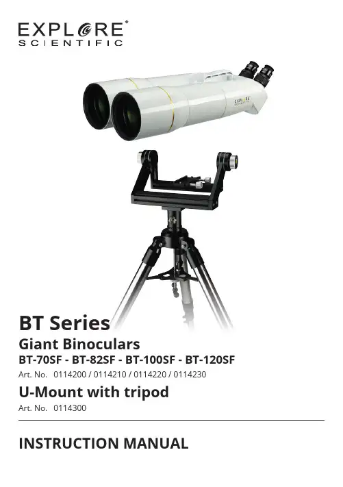
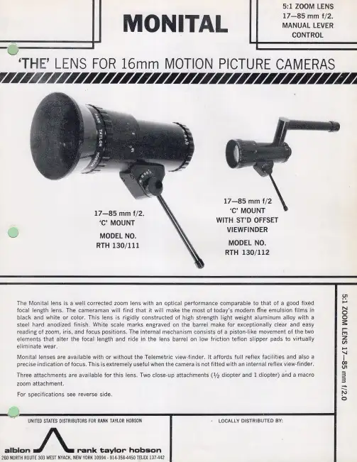
BT SeriesGiant BinocularsBT-70SF - BT-82SF - BT-100SF - BT-120SF Art. No. 0114200 / 0114210 / 0114220 / 0114230U-Mount with tripodArt. No. 0114300 INSTRUCTION MANUALGiant binoculars2x 62° LER eyepiece20mm ArTripodwith spacing plate and central screwU-Mountwith mounting plateand tripod head adapterTripodU-Mount11. F riction wheelsfor height adjustment 12. Movable height cradle 13. Fork arm14. Adapter plate for 15.15. 1/4" threaded screws 16. Dovetail rail 17. F ixing screws for 16.18. Turnable azimuthal axis 19. Fixing screw for 18.20. Mounting head21. Tripod head adapter1. Tripod head2. Tripod leg (upper part)3. Fixing screws for tripod leg4. Tripod leg (lower part)5. Spindle crank6. K nurled screw7. Central screw8. Spacing plate9. Washer 10. C-Clip21. Objective Lens 22. Dew/sun protection cap, extendable 23. Tube24. ¼" Connection thread 25. ⅜"-Connection thread* with unscrewable¼“ Connection thread adapter26. Transport handle27. Eyepiece, exchangeable 28. Eyepiece holder29. Eyepiece clamping ring 30. Focusing31. Interpupillary distance adjustmentGiant binoculars * for mounting on photo tripods with corresponding mounting head. ¼" connection thread can be unscrewed using a slotted screwdriver, thus exposing a "⅜"connection thread.When mounting the binoculars on a photo tripod with appropriate mounting head, make sure that the photo tripod and the mountinghead have sufficient load-bearing capacity!plate in the tripod head and fix it.adapter and the tripod. Tighten the tripod legs with the knurled screw.2. A ssemble spacing plate and central screw.6. F riction adjustment of the coupling for the height axis.them.tripod head. Place the U-Mount on the tripod head adapter.7. F riction adjustment of the coupling for the azimuth axis.bottom side of the binoculars.handle and tighten the fixing screws.guide of the U-Mount.12. B alance the binoculars at the centreof gravity.8. 2 x ¼" connection thread on the bottom side of the binocularsobservation. Possibly pull out theeyepiece holder.focusing.14. R emove the dust caps from theobjective lenses.Astronomical observations48Land observations48Tips on observationMoon*Star cluster M45 Pleiades*Orion nebula M42*Landscape*Birds*Ships** Sample images for illustration purposes. The actual image size and image quality depends on the selected eyepieces. Astronomical motifs are usually not visible in colour due to the long observation distance.EXPLORE SCIENTIFIC Eyepiece series EXPLORE SCIENTIFIC TELRADProjection viewfinder with baseEXPLORE SCIENTIFIC Nebula filters EXPLORE SCIENTIFIC Filter Set 2When using optional accessories, read separate instruction manual!Only use accessories authorized by the manufacturer!11Giant binoculars Product (Art. No.)Objective lens typeAperture (mm)Focal length (mm)Dimensions(LxWxH) (mm)Weight (kg)BT-70SF (0114200)achromatic (2 elem./1 gr.)70400370x213x122 3.4BT-82SF (0114210)achromatic (2 elem./1 gr.)82470445x226x122 4.3BT-100SF (0114220)achromatic (2 elem./1 gr.)100550520x270x155 6.8BT-120SF (0114230)achromatic (2 elem./1 gr.)120660654x290x1568.3Giant binoculars• C lean the lenses (eyepieces and/or objective lenses) only with a soft and lint-free cloth (e.g. microfibre cloth). To avoid scratching the lenses, use only gentle pressure with the cleaning cloth.• T o remove more stubborn dirt, moisten the cleaning cloth with an eyeglass-cleaning solution and wipe the lenses gently.• P rotect the device from dust and moisture! After use, particularly in high humidity, let the device acclimatise at room temperature for a short period of time, so that the residual moisture can dissipate. Put the dust caps on and store it in a dry and heated place.U-Mount and tripod• Clean the device only on the outside with a dry cloth.Bresser GmbHGutenbergstr. 2 · DE-46414 RhedeGermanywww.bresser.de·******************Errors and technical changes excepted.Manual_0114200-0114210-0114220-0114230-0114300_BT-Series-U-Mount_en_EXPSC_062021a。
Datalogic ........................................................................................1-113目录DS2100N&DS2400N ELT MFALCON M x4Gryphon TM I GBT4100 Gryphon TM I GBT4200 Gryphon TM I GBT4500 2D Gryphon TM I GD4132 Gryphon TM I GD4200 Gryphon TM I GD4500 2D Gryphon TM I GFS4400 2D Gryphon TM I GM4100 Gryphon TM I GM4200 Gryphon TM I GM4500 2D Gryphon TM I GPS4400 2D Gryphon TM L GD4300 Heron TM HD3100Heron TM HD3430JOYA TM X2Magellan TM 1500i Magellan TM 3410VSi Magellan TM 3200VSi Magellan TM 3400VSi Magellan TM 800i Magellan TM 9800iMatrix 220N TMMatrix 300N TMMatrix 410TMMemor TM 1Memor TM 10Memor TM 20Memor TM X3 PowerScan 7000-2D PowerScan PD9330 PowerScan TM PBT9501 PowerScan TM PD9130 PowerScan TM PD9500 PowerScan TM PD9531 PowerScan TM PM9100 PowerScan TM PM9500 PowerScan TM PM9501 QuickScan TM I QBT2131 QuickScan TM I QBT2400 QuickScan TM I QD2400 QuickScan TM I QD2500 QuickScan TM I QM2131 QuickScan TM I QM2400 QuickScan TM L QD2300 QuickScan TM Lite QW2100 QuickScan TM Lite QW2400 RIDA DBT6400-Retail SKORPIO TM X4 SKORPIO TM X5TD11002-34-56-78-910-11 12-13 14-15 16-17 18-19 20-21 22-23 24-25 26-27 28-29 30-31 32-33 34-35 36-37 38-39 40-41 42-43 44-45 46-47 48-51 52-57 58-59 60-61 62-63 64-65 66-67 68-69 70-71 72-73 74-75 76-77 78-79 80-81 82-83 84-85 86-87 88-89 90-91 92-93 94-95 96-97 98-99 100-101 102-103 104-105 106-107 108-109 110-111 112-113• DS2100N和DS2400N旨在为客户提供易于使用,具有优良读取性能的产品。

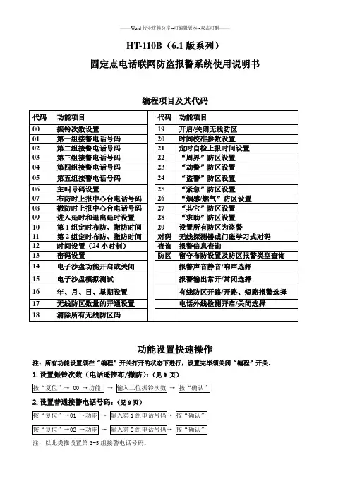
HT-110B (6.1版系列)固定点电话联网防盗报警系统使用说明书编程项目及其代码功能设置快速操作注:所有功能设置须在“编程”开关打开的状态下进行,设置完毕须关闭“编程”开关。
1.设置振铃次数(电话遥控布/撤防):(见9 页)→→2.设置普通接警电话号码:(见9页)→→注:以此类推设置第3-5组接警电话号码。
3、设置进入延时、退出延时时间:(见9页)4、设置第1组定时布、撤防时间:(见10页)→5、设置第2组定时布、撤防时间:(见10页)→6.设置当前时间(24小时制)及时钟自动校准功能:(见10页)→7.设置日期及星期(年、月、日、星期每项2位数,一位数前面补0):(见10页)→8、异地电话布/撤防密码设置:(见10页)9、探测器与主机对码:(见11页)→→→10、清除所有无线防区码:(见11页)11、遥控器与主机对码:(见11页)12、无线防区数量的开通:(见11页)13.无线防区开启/关闭:(见11页)14、防区报警类型设置(每次设置输入防区最多8个,多于8个须重复操作):(见12页)“盗警”:(见12页)16、电话接警处理方法:(见16页)一、概述HT-110B(6.1版)固定点电话联网防盗报警系统,引进美国进口原装芯片,微电脑控制技术,是一款全中文智能操作界面,大屏幕液晶显示,带万年历功能的报警系统。
该系统防区可达256个。
该系统由编程主机,无线/有线探测器,无线遥控器、无线门磁,脚挑开关等组成全方位防盗系统,可通过电信网络,拨打预设的报警电话或手机,实时传送报警信息,也可与安定宝(Contact ID通讯协议)及ADB2000报警中心台联网,组成电脑联网系统,报警时中心台显示电子地图、报警防区、时间等,便于及时处警。
二、主要功能特点★大屏幕中文液晶屏,24小时制时间显示,万年历功能,数据信息断电不丢失。
★8个有线防区,248个无线防区,可扩展为248个总线制有线防区。
(1-8防区为有线防区,其中8防区定为紧急防区,其它防区可通过功能设置为紧急防区)★设置防区报警类型,共分为七类:周界、劫警、盗警、紧急、烟感/燃气、其它、求助。
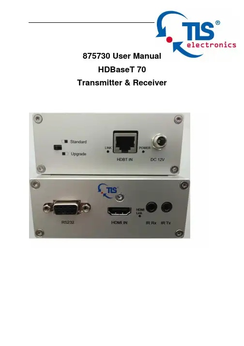
875730 User ManualHDBaseT 70 Transmitter & Receiver875730 User manualTLSelectronicsGmbHContact:************************Thank you for purchasing this product. For optimum performance and safety, please read these instructions carefully before connecting, operating or adjusting this product. Please keep this manual for future reference.SURGE PROTECTION DEVICE RECOMMENDED This product contains sensitive electrical components that may be damaged by electrical spikes, surges, electric shock, lightning strikes, etc. Use of surge protection systems is highly recommended in order to protect and extend the life of your equipment.875730 User manualTLSelectronicsGmbHContact:************************Table of Contents1. Introduction.........................................................................................4 2. Features...............................................................................................4 3. Panel Description..................................................................................5 4. Connection Diagram....................................................................9 5. Specifications.......................................................................................9 6. Package Contents................................................................................10 7. Maintenance.......................................................................................10 8. Warranty Policy.................................................................................10 9. Limitations of Warranty...............................................................................11 10. Exclusive Remedies.................................................................................12 11. RMA Policy (12)875730 User manualTLSelectronicsGmbHContact:************************IntroductionTLS HDBaseT 70 transmitter and receiver is a 70m (230ft) HDBaseT Extender. It transmits 1080P@60HZ at 48bit deep color via single Cat5e-AWG24-cable up to 70 meters (230ft). Bi-directional IR and RS232 can also be transmitted over the same cable. With support of POH (power over HDBaseT), only one power supply is needed at either transmitter or receiver.Features• HDMI v1.4 and HDCP compliant, support 1080p@60Hz, 3D, 4Kx2K@30Hz • Support 1080P@60Hz or VESA: 1920x1200@60Hz up to 70m (230ft) • Dolby TrueHD and DTS-HD master audio pass through HDMI output • Bi-Directional IR and RS232 pass through.• Power over HDBaseT supported, only one power supply needed at either transmitter or receiver side •With ESD ProtectionNote :The POH function is designed for powering compatible transmitter or receiver units of TLS only.875730 User manualTLSelectronicsGmbHContact:************************Panel Description875730 Transmitter1. RS232 connector2. HDMI link indicator3. IR TX jack4. HDMI input5.IR RX jack875730 User manualTLSelectronicsGmbHContact:************************1. Signal Link indicator2. Power status indicator3. EDID DIP switch ( UP=0, DOWN=1)[DIP]=0000: HDMI 1080p@60Hz, Audio 2CH PCM[DIP]=0001: HDMI 1080p@60Hz, Audio 5.1CH PCM/DTS/DOLBY [DIP]=0010: HDMI 1080p@60Hz, Audio 7.1CH PCM/DTS/DOLBY/HD [DIP]=0011: HDMI 1080i@60Hz, Audio 2CH PCM[DIP]=0100: HDMI 1080i@60Hz, Audio 5.1CH PCM/DTS/DOLBY [DIP]=0101: HDMI 1080i@60Hz, Audio 7.1CH PCM/DTS/DOLBY/HD [DIP]=0110: HDMI 1080p@60Hz/3D, Audio 2CH PCM[DIP]=0111: HDMI 1080p@60Hz/3D, Audio 5.1CH PCM/DTS/DOLBY [DIP]=1000: HDMI 1080p@60Hz/3D, Audio 7.1CH PCM/DTS/DOLBY/HD [DIP]=1001: HDMI 4K2K, Audio 2CH PCM[DIP]=1010: HDMI 4K2K, Audio 5.1CH PCM/DTS/DOLBY [DIP]=1011: HDMI 4K2K, Audio 7.1CH PCM/DTS/DOLBY/HD [DIP]=1100: DVI 1280x1024@60Hz, Audio None [DIP]=1101: DVI 1920x1080@60Hz, Audio None [DIP]=1110: DVI 1920x1200@60Hz, Audio None [DIP]=1111: EDID pass throughNOTE :The port will only read the DIP switch settings on power-up. The device must be powered offand then back on again for it to implement any change of the DIP switch settings.4. Upgrades DIP switch5. HDBT output6. DC 12V screw type connector875730 User manualTLSelectronicsGmbHContact:************************875730 Receiver1. Signal Link indicator2. Power status indicator3. Standard/Upgrade mode switch4. HDBT input5. DC 12V screw type connector875730 User manual TLSelectronicsGmbHContact:************************1. RS232 connector2. HDMI link indicator3. IR TX jack4. HDMI output5.IR RX jack875730 User manualTLSelectronicsGmbHContact:************************Connection DiagramSpecificationsBandwidth 2.97Gbps per Color Video input Transmitter 1XHDMI Type A, 19-pin, female Receiver 1xRJ45 Video output Transmitter 1xRJ45 Receiver 1XHDMI Type A, 19-pin, female IR input 2x3.5mm stereo jack IR output2x3.5mm stereo jack RS232 control 2x DB9Power Supply12V/2A DC, screw type connector Power Consumption 9.5WAudioPasses up to Dolby TrueHD or DTS-HD Master Audio Resolution Video: up to 4Kx2KVESA: up to 1920x1200Distance 230ft @ 1080p over CAT5e/6-AWG24 130ft @ 4Kx2K over CAT5e/6-AWG24 Dimensions 107x107x27mm Weight200gTemperature Operating 32°F to 104°F (0°C to 40°C) Storage-4°F to 140°F (20°C to 60°C) Rack-MountableRack ears includedNOTE : Specifications are subject to change without notice. Weight and dimensions are approximate .875730 User manualTLSelectronicsGmbHContact:*************************Package Contents• 1x 875730 Transmitter • 1x 875730 Receiver• 1x 12V/2A DC power supply• 1x IR Transmitter, 1x IR Receiver.MaintenanceClean this unit with a soft, dry cloth. Never use alcohol, paint thinner or benzene to clean this unit.Warranty PolicyTLS electronics products are warranted against defects in material and workmanship for two years from the date of shipment. During the warrantyperiod, TLS electronics will, at its option, repair or replace products that prove to be defective. Repairs are warranted for the remainder of the original warranty or a 90 day extended warranty, whichever is longer.For equipment under warranty, the owner is responsible for freight to TLS electronics and all related customs, taxes, tariffs, insurance, etc. TLSelectronics is responsible for the freight charges only for return of the equipment from the factory to the owner. TLS electronics will return the equipment by the same method (i.e., Air, Express, Surface) as the equipment was sent to TLS electronics.875730 User manualTLSelectronicsGmbHContact:*************************All equipment returned for warranty repair must have a valid RMA number issued prior to return and be marked clearly on the return packaging. TLS electronics strongly recommends all equipment be returned in its original packaging.TLS electronics obligations under this warranty are limited to repair orreplacement of failed parts, and the return shipment to the buyer of the repaired or replaced parts.Limitations of WarrantyThe warranty does not apply to any part of a product that has been installed, altered, repaired, or misused in any way that, in the opinion of TLS electronics, would affect the reliability or detracts from the performance of any part of the product, or is damaged as the result of use in a way or with equipment that had not been previously approved by TLS electronics.The warranty does not apply to any product or parts thereof where the serial number or the serial number of any of its parts has been altered, defaced, or removed.The warranty does not cover damage or loss incurred in transportation of the product.The warranty does not cover replacement or repair necessitated by loss or damage from any cause beyond the control of TLS electronics, such as lightning or other natural and weather related events or wartime environments. The warranty does not cover any labor involved in the removal and orreinstallation of warranted equipment or parts on site, or any labor required to diagnose the necessity for repair or replacement.The warranty excludes any responsibility by TLS electronics for incidental or consequential damages arising from the use of the equipment or products, or forany inability to use them either separate from or in combination with any other equipment or products.A fixed charge established for each product will be imposed for all equipment returned for warranty repair where TLS electronics cannot identify the cause of the reported failure.875730 User manual TLSelectronicsGmbHContact:*************************Exclusive RemediesTLS electronics ’s warranty, as stated is in lieu of all other warranties, expressed, implied, or statutory, including those of merchantability and fitness for aparticular purpose. The buyer shall pass on to any purchaser, lessee, or other user of TLS electronics ’s products, the aforementioned warranty, and shall indemnify and hold harmless TLS electronics from any claims or liability of such purchaser, lessee, or user based upon allegations that the buyer, its agents, or employees have made additional warranties or representations as to product preference or use.The remedies provided herein are the buyer ’s sole and exclusive remedies. TLS electronics shall not be liable for any direct, indirect, special, incidental, or consequential damages, whether based on contract, tort, or any other legal theory.RMA PolicyWhen returning product to TLS electronics for any reason, the customer should fill out the official RMA form to obtain a RMA number. Without the permission or approval, TLS electronics will be no responsible for any return.This can be initiated by emailing or calling your related sales.All requests are processed within 48 hours.Standard ReplacementFor customers that agree to return defective product to TLS electronics first, a Standard Replacement option is available.An RMA number must first be issued by sales. This RMA number will need to be referenced on the outside of the return shipment.Upon receipt of the defective product, TLS electronics will, at its discretion, either repair or replace the product and ship it out in the most expeditious875730 User manualTLSelectronicsGmbHContact:*************************manner possible. Subject to availability, the replacement product will be shipped on the business day following receipt of the defective product.In the event the product returned to TLS electronics has been discontinued (i.e. the product is no longer being manufactured by TLS electronics but is still under warranty), TLS electronics will, at its discretion, either repair or replace with recertified product.Once you have obtained an RMA numberAfter obtaining an RMA number from TLS electronics, you must send theproduct - freight prepaid - to TLS electronics. The TLS electronics RMA number must be prominently displayed on the outside of your package. If you send your product to TLS electronics without the RMA number prominently displayed on the outside of the package, it will be returned to you unopened.Please use a shipping company that can demonstrate proof of delivery. TLS electronics does not accept responsibility for any lost shipments unless proof of delivery to TLS electronics is provided.Please note:Product shipped to TLS electronics must be properly packaged to prevent loss or damage in transit.Shipping your RMA to TLS electronics using regular mailing envelopes is not acceptable, as they do not protect the product from damage during shipping.TLS electronics will not repair or replace a module that is shipped in such a way that the product is not properly protected.TLS electronics will not accept any product that has been damaged as a result of accident, abuse, misuse, natural or personal disaster, or any unauthorized disassemble, repair or modification .。
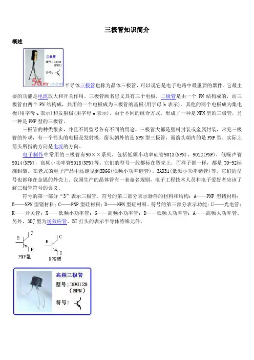
三极管知识简介概述半导体三极管也称为晶体三极管,可以说它是电子电路中最重要的器件。
它最主要的功能是电流放大和开关作用。
三极管顾名思义具有三个电极。
二极管是由一个PN结构成的,而三极管由两个PN结构成,共用的一个电极成为三极管的基极(用字母b表示)。
其他的两个电极成为集电极(用字母c表示)和发射极(用字母e表示)。
由于不同的组合方式,形成了一种是NPN型的三极管,另一种是PNP型的三极管。
三极管的种类很多,并且不同型号各有不同的用途。
三极管大都是塑料封装或金属封装,常见三极管的外观,有一个箭头的电极是发射极,箭头朝外的是NPN型三极管,而箭头朝内的是PNP型。
实际上箭头所指的方向是电流的方向。
电子制作中常用的三极管有90××系列,包括低频小功率硅管9013(NPN)、9012(PNP),低噪声管9014(NPN),高频小功率管9018(NPN)等。
它们的型号一般都标在塑壳上,而样子都一样,都是TO-92标准封装。
在老式的电子产品中还能见到3DG6(低频小功率硅管)、3AX31(低频小功率锗管)等,它们的型号也都印在金属的外壳上。
我国生产的晶体管有一套命名规则,电子工程技术人员和电子爱好者应该了解三极管符号的含义。
符号的第一部分“3”表示三极管。
符号的第二部分表示器件的材料和结构:A——PNP型锗材料;B——NPN型锗材料;C——PNP型硅材料;D——NPN型硅材料。
符号的第三部分表示功能:U——光电管;K——开关管;X——低频小功率管;G——高频小功率管;D——低频大功率管;A——高频大功率管。
另外,3DJ型为场效应管,BT打头的表示半导体特殊元件。
三极管最基本的作用是放大作用,它可以把微弱的电信号变成一定强度的信号,当然这种转换仍然遵循能量守恒,它只是把电源的能量转换成信号的能量罢了。
三极管有一个重要参数就是电流放大系数 b。
当三极管的基极上加一个微小的电流时,在集电极上可以得到一个是注入电流b 倍的电流,即集电极电流。

Uncompromising sound controlSennheiser HME 110 ATC/C3 headsets withclosed-ear noise protection provide excellentpassive attenuation for air traffic controllersor C3/Surveillance operators in particularlynoisy environments. A noise-cancellingmicrophone ensures excellent speechtransmission and soft ear pads and headbanddeliver long-wearing comfort. To set theheadset’s sound for varying soundenvironments, microphone sensitivity can besimply adjusted and a handy volume controlon the headset optimizes sound on the fly ifconditions change. It’s also possible tochoose between mono and stereo operation.A fully adjustable design ensures a firm fit forany user and a choice of cable lengths andjack options make it simple to adapt to anysystem or platform.BENEFITS AND FEATURES–Sennheiser Voice Clarity for accuratecommunication, provides a natural listeningexperience–Excellent speech transmission Noise-cancelling microphone reduces ambientnoise to improve intelligibility and reduce“call-back/read-back” events–Noise reduction with closed ear cupsoffering passive attenuation up to 40dB–Quick volume adjustment with built involume control on ear cup. Can be disabledif needed–Choice of mono/stereo with simpleswitching for dual communications sources–Flexible microphone boom - can be wornon either left or right-hand side–Cable/connector/PTT Wide range ofcables and connectors, can be customizedATC HeadsetsTechnical DataProduct HME 110 ATC HME 110 C3Art. No.500679507280EAN No.40 44155 00857 940 44155 23762 7UPC No. 6 15104 11322 0 6 15104 31485 6HeadphonesSound pressure level:dB SPL @ 1 KHz, 0.5 V92 ±3 dB92 ±3 dBdB SPL @ 1 KHz, 1 mW90 ±3 dB90 ±3 dBdB SPL @ 1 KHz, 1V98 ±3 dB98 ±3 dBMax SPL [dB]120120THD, total harmonic distortionat 100 dB SPL at 1 kHz< 1 %< 1 %Frequency response45 – 15,000 Hz 45 – 15,000 HzImpedance300 Ω stereo / 150 Ω mono300 Ω stereo / 150 Ω mono Power rating200 mW200 mWMicrophoneMicrophone type Electret, MKE 45-1Electret, MKE 45-1Output voltage40 mV/Pa ±1dB @ 1kHz40 mV/Pa ±1dB @ 1kHzPick-up pattern Noise-cancelling, uni-directional Noise-cancelling, uni-directional Supply voltage 8-16 VDC8-16 VDCFrequency response 100 – 5,000 Hz100 – 5,000 Hz Recommended load impedance 150 – 2,200 Ω 150 – 2,200 ΩGeneral DataCable length 1.5 m / 59.1 in 1.85 m / 72.8 inConnector/cable termination 5.25mm jack plug microphone6.35mm jack plug headsetOpen end, pre-tinned cable Wearing style Headband, double-sided Headband, double-sided Contact pressure10 N10 NEar coupling Closed, Circumaural Closed, CircumauralWeight of headset350 g / 12.35 oz350 g / 12.35 ozStorage temperature−55 °C to +70 °C−67 °F to +158 °F −55 °C to +70 °C −67 °F to +158 °FOperating temperature−10 °C to +55 °C+14 °F to +131 °F −10 °C to +55 °C +14 °F to +131 °FWarranty 5 years 5 yearsATC Headsets0902 02-2018Sennheiser Communications A ⁄ SIndustriparken 27, DK-2750 Ballerup, Denmark ATC Headsets Content of deliveryBox content –Headset–Cable clip–Safety guide–Quick guideAccessories*Product name Product description Art. No EAN No.UPC No.MZW 45Windscreen packed 09280440 06087 92804 2 6 15104 92804 6HZC 08Cable clip, black 52578740 44155 03178 2 6 15104 14651 8HMS 26-2Headband padding, 2 pcs 55026240 44155 08518 1 6 15104 24120 6Comfort earpads 1 pair with disc 51760740 44155 02036 6 6 15104 13143 9* Only use accessories supplied or recommended by SennheiserTechnical DataPackaging HME 110 ATC HME 110 C3Dimension of product packaging (W x H x D)230 x 170 x 105 mm 9.06 x 6.69 x 4.13 in 230 x 170 x 105 mm9.06 x 6.69 x 4.13 inPackage weight (incl. complete product and packaging)562 g / 19.82 oz 532 g / 18.77 ozUnit s in distributor master carton 1010Master carton weight incl. products6.48 kg / 14.29 lbs 6.18 kg / 13.62 lbsDimension of master carton (W x H x D)590 x 290 x 350 mm 23.22 x 11.42 x 13.78 in 590 x 290 x 350 mm23.22 x 11.42 x 13.78 inUnit pack/end user 11。
APAW.S1871indicated in the instructions, wiring diagram.Control unit subassemblies, Models D2212B, D2212BE, followed by suffix "LC".Control unit accessories, keypads, Models D202A, D220A, D222A, D223A, may be suffixed by TD; Models D621, D621B, D621W, D623,D623B, D623W, D625, D625B, D625W for use with control panels indicated in the installation instructions.Models D720 and D1255, may be followed by suffixes R, TD or W, for use with control panels indicated in the installation instructions (covered under File S5579); Models D1260, D1260B, D1260R, D1260W, D1260BLK.Control unit subassembly, Model ICP-SDI-9114, for use with control panels and keypads indicated in the installation instructions.Control unit accessories, Models D133, D134 relay modules.Control unit accessory, Model D208 zone expansion module.Control unit subassembly, Model D208LC zone expansion module.Control unit accessories, Models D9210B, D9210BC, D9210BLC access control modules. (Covered under File S5579).Control unit accessories, Models SK-820 Data Repeater, SC9002 Printer (Covered under S5579).Control unit modules, Models SC-4000D, SC-4000DSC, SC-4000 Guard Unit RF transmitters (Covered under S5579).Control unit subassembly, Model LS-500 Line Simulator, Ethernet Module, Model B420 (Covered under S5579).Control unit accessory, Network Interface Module, Model DX4020 (covered under File S5579).Control unit subassembly, GPRS/GSM IP Communicator, Model ITS-DX4020-G (+8).Communicator interface module, Model B450(+12).Control unit accessories, printer interface, Model D9131A. For use with Radionics products where referenced in the installation instructions. Control unit subassemblies, Models D6412LC, D6412M, D4412LC, D4412M, DX2010, DX3010.Control unit subassembly, Ethernet Module, Model B420 (++)(Covered under S5579).Control unit accessory, RF Receiver, Model RF3224. Suitable for use with transmitters indicated in the installation instructions.Models D4412, D4412LT, D6412, D6412LT. For all applications, the Model D8108A or D8108AH, attack resistant enclosure and a Listed local sounding device are required. Suitable for use with Models D621, D621W, D623, D623W, D625, D625W Command Centers. The units may include Listed modules and subassemblies referenced in the manufacturer's operation, installation manual. Suitable for bank safe and vault applications when used in conjunction with the Listed Model S110 Electronic Sounding Device by Rothenbuhler Engineering.Control unit subassembly, C900V2+ dialer capture module.Enclosure, Model ULPS (++).Computer, Model B-010 (+2) for use with receiver model D6600.Monitor, Model B-008 (+3).Digital alarm communicator receiver, Model 6100IPv6. The Model 6100IPv6 Connettix Receiver is suitable for use as a commercial DACR and PSDN communicator.Control unit accessory, Model ISW-D8125CW-V2 (+7) wireless Interface module for use with separately Listed ISW-EN-4200 Wireless Inovonics RF Receiver. Compatible with control panels D9412GV3/D7412GV3/D7212GV3, D9412GV2/D7412GV2, D7212GV2.Subassembly, Model B46 Communicator Status Indicator (+17).Model B465 Connettix Universal Dual Path Communicator (+17).+ - Complementary Listed to AMCX, AMCX7, UTOU, UTOU7, NBSX, NBSX7, APAW7, APOU, APOU7.++ - Complementary Listed to ALVY, AMCX, AOTX, APOU, NBSX, UOXX, UTOU.(+2) - Complementary Listed to UOJZ, UOJZC, AMCX7, APAW7, APOU, APOU7.(+3) - Complementary Listed to UOXX, UOXXC, AMCX7, APAW7, APOU, APOU7.(+4) - Complementary Listed to AMCX, AMCX7, APAW7.(+5) - Suitable for Encrypted Line Security when employing Listed Models DX4020 or C900V2 via PSDN only.(+6) - Complementary Listed to UOJZ, AMCX, APOU, ALVY, AOTX, NBSX, UTOU.(+7) Complimentary Listed to APOU, AMCX, UTOU, AOTX, NBSX.(+8) Complimentary Listed to UOJZ, AMCX, UTOU, NBSX, APOU.(+9) Complimentary Listed to UOJZ, APOU, AMCX, APAW, ALVY, AOTX, UTOU, NBSX, AMTB, ANET, Suitable for Encrypted Line Security when employing Listed Models DX4020 or C900V2 via PSDN only.(+10) Complimentary Listed to UOJZ, APOU, AMCX, APAW, ALVY, AOTX, UTOU, NBSX, AMTB, ANET, Suitable for Encrypted Line Security when employing Listed Models DX4020 or C900V2 via PSDN only.(+11) Complimentary Listed to APOU, APOU7, AMCX, AMCX7, AOTX, AOTX7, APAW7, UTOU, UTOU7, NBSX, NBSX7, AMTB, ANET.(+12) Complementary Listed to UOJZ, AMCX, AMCX7, APAW7, APOU, APOU7, AOTX, AOTX7, UTOU, NBSX, AMTB, ANET.(+13) Complementary Listed under AMCX, AMCX7, AMTB (ANSI/SIA CP-01-2010), ANET, AOTX, AOTX7, APAW7, APOU, APOU7, NBSX, NBSX7, UTOU, UTOU7.(+14) Complementary Listed under AMCX, AMCX7, AMTB, ANET, AOTX, ATOX7, APAW7, APOU, APOU7, NBSX, NBSX7, UTOU, UTOU7, UOJZ, ANSI/SIA CP-01-2010.(+15) Complementary Listed under AMCX, AMTB, ANET, AOTX, APOU, NBSX, UTOU, ANSI/SIA CP-01-2010.(+16) Complimentary Listed to APOU, APOU7, AMCX, AMCX7, AOTX, AOTX7, APAW7, UOJZ, UTOU, UTOU7, NBSX, NBSX7, AMTB, ANET.(+17) Complementary Listed under AMCX, AMCX7, AMTB, ANET, AOTX, ATOX7, APAW7, APOU, APOU7, NBSX, NBSX7, UTOU, UTOU7, UOXX, ANSI/SIA CP-01-2010.Model StandardLineSecurityEncryptedLineSecurityNo LineSecurityConditions andNotesD6600 Netcom Receiver X——when used with compatible control unitD6600 Netcom Receiver—X—when used with a compatible control unit and ListedModel DX4020 Network Interface Module or the Listedmodel C900V2 Dialer Capture Module along with theD6680 network adapter.D6500 Digital AlarmCommunicator Receiver——X—D7412, D9412GV2, D7412GV2,D7212GV2, D9412GV3,D7412GV3, D7212GV3 DACTUnitsX———B3512, B4512, B5512 Control Units X——With onboard IP connection, B426 module, B440,B441, B442 or B443 cellular communication modulewith Bosch Listed D6600 or D6100IPv6B8512G(+16), B8512G-E (+16), B9512G (+16), B9512 (+16)—X—With onboard IP connection, B426 module, B440,B441, B442 or B443 cellular communication modulewith Bosch Listed D6600 or D6100IPv6B3512, B4512, B5512 ControlUnits——X When using B430 DACT communication moduleB8512G(+16), B8512G-E(+16), B9512G (+16), B9512(+16)——X When using B430 DACT communication moduleD7412, D9412GV2, D7412GV2, D7212GV2, D9412GV3,D7412GV3, D7212GV3 DACT Units —X—when used with Listed Models DX4020 or C900V2 viaPSDN onlyD2212B, D2212BE(may be followed by suffix "LT") Control Units —X—when used with Listed model C900V2 Dialer CaptureModule for use with receivers as indicated in theinstallation instructionsD4412, D4412LT, D6412, D6412LT Control Units —X—when used with the model C900V2 dialer capturemodule for use with receivers as indicated in theinstallation instructionsD6100IPv6 Digital AlarmCommunicator Receiver—X——ITS-DX4020-G X X—When used with Bosch control panels, modelsD9412GV2, D7412GV2, D7212GV2, D9412GV3,D7412GV3, D7212GV3, and Bosch receivers, modelsD6600 and D6100I.Trademark and/or Tradename: "Safecom"。
Eris® HD10BTProfessional Headphones with Active Noise Canceling and Bluetooth® wireless technology Owner’s Manual®1 Overview — 11.1 Introduction — 11.2. What is in the box — 11.3. Companion PreSonus Products — 22. Hookup — 32.1. Right Earpiece Connections and Controls — 32.1.1.Bluetooth Pairing and Powering — 32.1.2.Track Navigationand Bluetooth volume — 32.1.3.Phone Call Controls — 42.1.4. Hardwiring — 52.2. Left Earpiece Connections and Controls — 52.2.1.Active Noise Canceling (ANC) — 52.2.2. Charging — 51 Overvi ew1.1 Introduct i onEris HD10BT Owner’s Manual11.1 IntroductionThank you for purchasing the PreSonus® Eris™ HD10BT professional headphoneswith Active Noise Canceling and Bluetooth wireless technology. PreSonus®Eris HD10BT headphones provide studio-quality audio performance with themobility and freedom of Bluetooth connectivity. Active Noise Canceling (ANC)reduces ambient sounds by up to 18 dB – so whether you’re walking down abusy street, or sitting in the middle seat on an airplane, you can listen to yourfavorite music, podcasts, or binge-worthy TV series in vivid sonic fidelity.PreSonus Audio Electronics is committed to constant product improvement,and we highly value our customers and their creative endeavors. Weappreciate the support you have shown us by purchasing your Eris HD10BTheadphones and are confident that you will enjoy it for years to come!1.2. What is in the boxYour Eris HD10BT package contains the following:PreSonus Eris HD10BT professional headphonesQuick Start Guide1M 1/8” (3.5mm) TRS-TRS cable1/8” (3.5mm) TRS-to-1/4” (6.35mm) TRS adapter1M USB charging cable1 Overv i ew 1.3. Companion PreSonus ProductsEris HD10BT Owner’s ManualHardshell carrying casePreSonus Health, Safety, and Compliance Guide for Headphones1.3. Companion PreSonus ProductsThanks for choosing PreSonus! As a solutions company, we believe the best way totake care of our customers (that’s you) is to ensure that you have the best possibleexperience from the beginning of your signal chain to the end. To achieve this goal,we’ve prioritized seamless integration throughout every design phase of theseproducts from day one. The result is systems that communicate with each otheras intended – straight from the box – without excessive configuration hassles.We’re here for you. Find out more at 2.2.1. Right Earpiece Connections and Controls2.1.1. Bluetooth Pairing and PoweringThe following controls are available for use with yourfavorite Bluetooth device while listening to audio:1. Volume Up / Prev Track. Press once to increase the Bluetoothplayback volume. Press and hold to navigate to the previous track.2. Play/Pause. Press this button to remotely start andstop playback on your Bluetooth device.3. Volume Down / Next Track. Press once to lower the Bluetoothplayback volume. Press and hold to advance to the next track.2.1.3. Phone Call ControlsThe center button can also be used to remotely answer or reject calls whenyour phone is paired via Bluetooth to your Eris HD10BT headphones:2.1.4. HardwiringYour Eris HD10BT headphones can be used wired when the battery islow, or if you would like to connect them a device that does not offerBluetooth. The 1/8” TRS jack is located on the bottom of the RightEarpiece. Use the included cable or any standard 1/8” TRS cable.2.2. Left Earpiece Connections and Controls2.2.1. Active Noise Canceling (ANC)Dinner is ServedAdded bonus: PreSonus’ previously Top Secret recipe for…Chicken and Andouille GumboIngredients:• 1 C All-Purpose flour•¾ C Vegetable Oil• 1 large onion (diced)• 1 small onion (quartered)• 6 celery stalks (diced)• 1 large green bell pepper (diced)• 3 cloves garlic (2 minced, 1 whole)• 1 lb link Andouille sausage• 4 Chicken leg quarters• 4 qt water• 4 bay leaves• 1 tsp thyme• 1 tsp Old Bay seasoning•1-2 C frozen okra, sliced•¼ C fresh parsley, minced• 6-8 eggs (optional)Cooking Instructions:1. In a large pot, combine whole chicken leg quarters, water, quartered onion, Old Bay, 2 bay leaves and 1 whole clove garlic.Cover and bring to a low boil. Simmer stock until chicken is falling off the bone. Remove the chicken and set aside. Discard the onion, bay leaves, and garlic, reserving the liquid.2. In a heavy saucepan, heat 1 Tbsp of the oil on medium high heat and brown the andouille until it is cooked through. Setaside sausage for later.3. In the same saucepan, add and heat remaining oil. Slowly add flour 1-2 Tbsp at a time, stirring continuously. Continuecooking and stirring the roux until it is a dark brown (it should look like melted dark chocolate). Be careful to not to get the oil too hot or the flour will burn and you’ll have to start over.4. Once roux has reached the correct color, add diced onion, celery, green pepper, and minced garlic. Cook until vegetablesare very tender. Do not cover.5. Slowly add 1 quart of chicken broth and bring to a low boil, stirring constantly.6. Transfer roux mixture to a soup pot and bring to low boil. Do not cover, the roux will settle on the bottom of the pot and burn.7. Add remaining chicken broth, bay leaves, and thyme. Simmer for 30 minutes.8. While gumbo is simmering, debone and shred chicken and slice the andouille.9. Add chicken and andouille to gumbo and return to a simmer. Simmer for 30-45 minutes.10. Stir in frozen okra and parsley and bring to a rolling boil.11. Optional: Crack one egg into a teacup and quickly pour into the boiling gumbo. Repeat with the other eggs being carefulnot to cluster them too closely. After all the eggs have risen back to the surface, reduce heat and simmer.12. Correct seasoning with salt and pepper (red, white and/or black) if necessary.13. Serve over rice with potato salad.Serves 12©2021 PreSonus Audio Electronics, Inc. All Rights Reserved. AudioBox USB, Capture, CoActual, EarMix, Eris, FaderPort, FireStudio, MixVerb, Notion, PreSonus, PreSonus AudioBox, QMix, RedLightDist, SampleOne, Sceptre, StudioLive, Temblor, Tricomp, WorxAudio, and the Wave Logo are registered trademarks of PreSonus Audio Electronics, Inc. Studio One is a registered trademark of PreSonus Software Ltd.Mac, macOS, iOS, and iPadOS are registered trademarks of Apple, Inc., in the U.S. and other countries. Windows is a registered trademark of Microsoft, Inc., in the U.S. and other countries.Bluetooth is a registered trademark of Bluetooth SIG.Other product names mentioned herein may be trademarks of their respective companies. All specifications subject to change without notice... except the recipe, which is a classic.Eris® HD10BTProfessional Headphones with Active Noise Canceling and Bluetooth® wireless technology Owner’s ManualBaton Rouge • USAPart# 70-52000141-A。