吉林大学毕业设计模板
- 格式:pptx
- 大小:2.97 MB
- 文档页数:21
化工学院毕业设计(论文)设计论文题目:******************学院:吉林工业职业技术学院专业:过程装备与控制技术学生:****指导教师:赵继平完成时间:2012年12月20日诚信声明本人声明:我所呈交的本科毕业设计论文是本人在导师指导下进行的研究工作及取得的研究成果。
尽我所知,除了文中特别加以标注和致谢中所罗列的内容以外,论文中不包含其他人已经发表或撰写过的研究成果。
与我一同工作的同志对本研究所做的任何贡献均已在论文中作了明确的说明并表示了谢意。
本人完全意识到本声明的法律结果由本人承担。
申请学位论文与资料若有不实之处,本人承担一切相关责任。
本人签名:日期:2012 年12 月20 日毕业设计(论文)任务书设计(论文)题目:************学院:吉林化工学院专业:过程装备与控制技术学生:*** 指导教师:赵继平1.设计(论文)的主要任务及目标(1) 设计一年产28000吨甲醛生产装置工艺与设备设计;(2) 原料为甲醇,其中工业甲醇含量为1.35%(量分数,下同),含水0.65,无其它杂质;(3) 工艺条件为:反应温度873-913K,年生产时间300天,甲醇转化率93.3%,甲醛收率83%,原料配比(质量比)甲醇:水:空气=1:0.58:1.338;(4) 副产物组成:CO2 4.0%、CO 0.5%、O2 0.2%、H2 17%、N2 76.3%、H2O 2%。
2.设计(论文)的基本要求和内容(1) 工艺设计①生产方法的选择;②反应器的物料衡算和热量衡算;③反应器主要工艺尺寸计算。
(2) 设备计算①反应器的机械强度及有关参数的确立;②辅助设备的选择或确立。
(3) 提交设计文件①设计说明书一份;②设计图纸:工艺流程图、反应器装配图、平面布置图各一份。
③反应器主要工艺尺寸计3.主要参考文献[1] 梁凤凯、舒均杰.有机化工生产技术[2] 陈炳和、许宁.化学反应过程与设备[3] 梁玉华、白守礼.物理化学[4] 王振中.化工原理[5] 蔡纪宁、张秋翔.化工设备机械基础课程设计指导书社,2006.[6] 化学工业出版社组织编写.化工生产流程图[7] 王绍良.化工设备基础28000吨/年甲醛生产装置工艺与设备设计摘要甲醛(formaldehyde;methanol)是一种比较重要的有机化工产品,是醛类中最简单的化合物。
本科生毕业设计(论文)翻译资料中文题目:配合新一代液力变矩器的柴油动力线的一些特性英文题目:some properties of a diesel driveline with hydrodynamic torque converters of thelastest generation学生姓名:学号:班级:专业:机械工程及自动化指导教师:吉林大学机械科学与工程学院Some properties of a diesel drive line withhydrodynamic torque converters of the latestgenerationAbstractDynamic properties of a drive line with a controlled Diesel engine, hydrodynamic transmission mechanism, additional gearing and a loading-working machine producing common monoharmonic loading are investigated. Solution of the dynamic problem is based on phenomenological experimental data: drivingtorque-speed characteristic in the part of the prime mover and so-called external static characteristic in the hydrotransmission part. The non-linear task is solved by a modified harmonic balance method that was described in preceding publications by the author.Keywords: Machine drive line; Controlled Diesel drive; Hydrodynamic torque converter; Working machine; Periodic loading; Stationary dynamic stateNomenclature and abbreviationsa, b --- ------Coulomb and viscous non-dimensional friction lossesA i,B i --- ----coefficients in mathematical expression of torque-speed characteristic i, i m ----------kinematic transmission, supplementary gearing transmission ratio -------mean reduced moment of inertia in driving and loading partI, I, k K ---------tangent slopes of λ(i) and K(i) curves respectivelykλK -------------moment transmissionM ------------Diesel-engine momentM D(ω, z) ----controlled torque-speed driving characteristicM Dmax(ω), M Dmin(ω) ---torque-speed characteristic for maximal and minimal fuel supplyM1, (), M2, () ---pump loading moment and turbine driving momentM T1, M T2 ----friction loss moment in driving and loading partM z, M za ----mean value and amplitude of loading moment-------------hydrodynamic converter characteristic radius吉林大学本科毕业论文外文翻译t -------------timeT, T D------------Watt regulator and Diesel-engine time constantu, z ---------gas lever and regulator displacementw -----------common dynamic variableε -----------regulator structural parameterζ -----------regulator damping ratioλ -----------coefficient of rotation momentν -----------loading angular velocity, π-------index denoting mean value and periodical component---------hydraulic medium density----------rotation angleω1, (), ω2 ---pump and turbine angular velocityDM ------Diesel-engineG, G D ---additional and Watt-regulator gearingHdPT ---hydrodynamic power transmissionIJ --------InjectorLM ------loading mechanism (working machine)P, R, T---pump, reactor, turbineArticle OutlineNomenclature1. Introduction2. Mathematical model of the system3. Stationary dynamic solution at monoharmonic loading4. Results evaluation and concluding remarks1. IntroductionDynamic properties of a drive line (actuating unit) consisting of a controlled Diesel engine (DM), hydrodynamic power transmission system (HdPT), additional gearing (G) and a loading mechanism (LM) or working machine are investigated. The working machine loads the prime mover and the transmissions with a prescribed moment. A simple idealised schematic layout of the complete system is given in Fig.1. The considered Diesel engine is a standard production: ZETOR 8002.1 controlled by a mechanical (Watt’s) or electronic regulator R D governing fuel injector IJ. In the place of the hydrodynamic power transmission there are gradually applied hydrodynamic torque converters of the latest generation that have been projected吉林大学机械科学与工程学院and tested in WUSAM (Research and Projecting Institute of Machines and Mechanisms), j.s.c. Zvolen, Slovakia. These converters represent a three component assembly composed of a rotational pump (P), turbine (T) and a reactor (R) that may revolve in one direction as a free wheel. Advantage of these converters is the fact that their external dimensions and the dimensions of their individual components are identical and they may be mutually changed and arbitrarily combined in order to reach demanded properties. They differ only by internal configuration and blade geometry. According to [1] up to now more than 70 various types have been experimentally tested and from them the ones have been chosen that optimally fulfilled required properties. The mechanical system under consideration represents a sophisticated energy transfer chain from a source––prime mover to working mechanism. Because every real drive is of finite power, any periodic loading always evokes vibrations of all the dynamic variables even though we suppose all the connecting shafts and gearings rigid and backlash free. The influence of dynamic loading on the prime mover may be just controlled by a suitable choice of the torque converter.Fig. 1. Schematic layout of the Diesel drive line.In the paper influence of constant and periodic loading on time course of all the dynamic variables of the system (and particularly on the variables of the prime mover) is investigated at application of some selected types of hydrodynamic torque converters of the latest generation. For fulfilling this task it is necessary to create a suitable mathematical model of the whole combined system and then find its stationary solution corresponding to a required loading.2. Mathematical model of the system吉林大学本科毕业论文外文翻译At the beginning it is necessary to emphasize that mathematical modelling of the drive line in question is based, in our approach, on knowledge of the published phenomenological data: stationary torque-speed characteristic of the prime mover and so-called external static characteristic of the applied hydrodynamic torque converter. It is a much simpler process than modelling based on thermodynamic equations of burning fuel mixture in the Diesel engine and on hydrodynamic equations of real streaming working medium in very complicated cavities of the torque converter. The characteristics are usually given by manufacturer of the individual system components. This is different and simpler approach to solution of the problem than one may find e.g. at Ishihara [2], Hrovat and Tobler [3], Kesy and Kesy [4], Laptev [5] and some others. The derived dimensional and non-dimensional mathematical models of the mechanical system are introduced in [6]. Thenon-dimensional, reduced, so-called single-shaft model (in the driving and loading part), was derived in the form of combined system of the following differential and algebraic equations:(1)(2)(3)(4)M2=KM1, (5)λ=λ(i), (6)K=K(i), (7)(8)吉林大学机械科学与工程学院(9) where the meaning of the individual symbols is explained in nomenclature. In the non-dimensional model all the dynamic variables and parameters are expressed by means of properly chosen relative standard quantities so that the model of the system might be the most simple. Transformation of the original equations system to the non-dimensional form Figs. (1), (2), (3), (4), (5), (6), (7), (8) and (9) is described in detail in [6]. As for this cited paper, it is necessary to say that the relative standard value of loading angular frequency has been settled according to the relation, where in denominator is relative standard value of time. For this value,the time constant of the regulator has been just chosen, i.e. , where therelated dimensional dynamic variables are distinguished by upper bars. The introduced mathematical model has nine variables: M, M1, ω1, z, λ, K, i, M2, ω2 and their meaning is explained in nomenclature. The first three equations represent mathematic model of the prime mover where in inertia moment I there is includedinertia moment of the pump and equivalent part of the working medium because driving and pump shafts are connected by a rigid clutch. The right side of Eq. (3) represents the controlled stationary torque-speed characteristic for which it holds: M D(ω1,z)=M Dmax(ω1)-[M Dmax(ω1)-M Dmin(ω1)]z, (10) where M Dmax(ω1), M Dmin(ω1) represent its non-dimensional extreme branches for maximal and minimal fuel supply and z is the non-dimensional regulator deviation.If the experimentally measured dependences M Dmax(ω1), M Dmin(ω1) are expressed by second degree polynomials then the controlled non-dimensional torque-speed characteristic has the form:(11) From the introduced model it is evident that at chosen parameter value u driving speed growth causes regulator displacement to increase and fuel supply to decrease. The idealised controlled torque-speed characteristic for a chosen parameter value u (gas lever displacement) is schematically depicted in Fig. 2. From Eq. (2) it is evident that the structural parameter ε must be chosen in such away that regulator self-oscillations should not occur. Eqs. Figs. (4), (5), (6), (7) and (8), in the sense of considerations in [6], represent the dynamic equations of the torque converter. Eq. (9) represents simplified motion equation of the loading mechanism under assumptiondoes not depend on rotation angle . In thisthat the reduced inertia moment Ireduced inertia moment there is involved inertia moment of the turbine with吉林大学本科毕业论文外文翻译equivalent part of the working medium too. It is obvious that in this inertia moment and in all moments of the loading mechanism there is considered gear ratio i m of the supplementary gearing of the originally non-reduced system. Eqs. Figs. (6) and (7) represent the external static characteristic of the hydrodynamic transmission, i.e. formal dependences of λ and K on the kinematic ratio i and the dependences are given for every converter type in graphical form. The dynamic variables λ and K are defined in non-dimensional form very simply by non-linear relations Figs. (4) and (5). In a general way these non-dimensional variables are defined by means of dimensional values (distinguished by upper bars) as follows:(12) where individual symbol meaning may be found in nomenclature. As we have chosen (according to Fig. 2) for the relative standard value of angular velocity the idle motion angular velocity of the Diesel engine at maximal fuel supply, i.e. at z = 0, then from Figs. (4) and (12) it is evident that the relative standard moment value is(13)It means that if for the applied drive s−1 and all the applied convertertypes have equal characteristic radius m and if we consider mean valuekg m−3 at stationary thermic regime then the relative standard value of themoment is N m for all the considered converter types. The external static characteristics of the applied converters with internal labelling: M350.222,M350.623M, M350.675, M350.72M3M, are (according to the measuring records [7]) successively introduced in Fig. 3(a)–(d). When the torque-speed characteristic is known and the measured dependences Figs. (6) and (7) are at disposal, it is possible to solve the combined system of differential and algebraic equations Figs. (1), (2), (3), (4), (5), (6), (7), (8) and (9). This is a little complicated task because the differential and algebraic equations in the accepted mathematical model arenon-linear. Stationary dynamic state of the system was calculated by a modified harmonic balance method that is fully described in [8].吉林大学机械科学与工程学院Fig. 2. Idealised diagram of the driving torque-speed characteristic.Fig. 3. External static characteristics of the hydrodynamic power transmissions: M350.222,M350.623M, M350.675, M350.72M3M.3. Stationary dynamic solution at monoharmonicloadingIn this section stationary solution of the system Figs. (1), (2), (3), (4), (5), (6), (7), (8) and (9) will be looked for always with the same prime mover and successively considering all the converters types whose external static characteristics are introduced in Fig. 3(a)–(d). If each of the nine dynamic variables is denoted by a common symbol w≡M, M1, ω1, z, λ, K, i, M2, ω2 then, in accordance with applied method, every dynamic variable may be formally expressed as a sum of its mean and its centred periodic component, i.e.:w=w+w π. (14) Following the mentioned method, on restrictive presumption that it holds:MM z→wπw, (15)吉林大学本科毕业论文外文翻译the system Figs. (1), (2), (3), (4), (5), (6), (7), (8) and (9) splits into twoindependent systems of equations: a system of non-linear algebraic equations for calculationw and a combined system of linearised differential and algebraic equations for calculation w π. If one considers that friction losses in the driving part are implicitly expressed already in the torque-speed characteristic of the drive and in the external static characteristic of the applied hydrodynamic torque converter and friction losses in the loading part are supposed as a combination of Coulomb and viscous friction, i.e.:M T 2=a +bω2, (16)then the non-linear algebraic system has the form:(17)The combined system of the linearised differential and algebraic equations is(18)where for writing abbreviation it is denoted:吉林大学机械科学与工程学院(19) The solution process of both equation systems Figs. (17) and (18) is introduced in [8]. The system of non-linear equations (17) was calculated for three parameter levels u (u = 0.3, 0.4, 0.6) that respond to 30%, 40%, and 60% of the maximal gas lever displacement. To each chosen parameter value u, a certain driving angular velocity interval responds. From Fig. 2 and from Eq. (2) it is evident that for a chosen value u the corresponding mean driving angular velocity value must lie in interval:ω1ω1b, (20)ωwhere for border values of the interval it holds:(21) For the chosen parameter value u = 0.3 and for different mean values M z, the calculated mean values w(for the drive line with given drive and all the consideredconverter types) are introduced in diagrams in Fig. 4(a)–(d). Analogical mean values w of the same variables corresponding with the parameter u = 0.4 are in Fig.5(a)–(d). Finally, the calculated mean values w corresponding with parameteru = 0.6 and identical torque converter types are depicted in Fig. 6(a)–(d). Here it is important to remind that x-coordinates in Fig. 4, Fig. 5 and Fig. 6 represent the mean angular velocity interval (20) gradually for parameters u = 0.3, 0.4, 0.6 and the decimal fractions on this section denote only its decimal division. From the calculated mean values w in Fig. 4, Fig. 5 and Fig. 6 and from the introducedexternal static characteristics in Fig. 3a complete nine of the mean values w can be determined for any mean loading value Mand estimated loss moment value M T2in the loading part. When this complete nine w is known then it is possible, in the sense of the applied method, to construct all the constant coefficients of the combined differential and algebraic system (18) for calculation wπ. This system is already linear and may be solved by known classical methods. First of all, we take interest in stationary dynamic solution. In sense of the procedure one may express the centred periodic component of every dynamic variable in the form:wπ=M za(W c cosνt+W s sinνt), (22) where notations W c, W s represent cosine and sine components of the dynamic factor (transmissibility) of corresponding dynamic variable. Detailed computing procedure is introduced in [8]. For transmissibility of the centred periodic component of every dynamic variable it holds:(23)As an example in Fig. 7, Fig. 8, Fig. 9, Fig. 10 and Fig. 11 there are successively introduced dynamic characteristics of the centred periodic components of dynamic variables: moment (M) and angular velocity of the drive (ω1), loading moment of the pump (M1), moment (M2) and angular velocity of the turbine (ω2) for the system with hydrodynamic converter M350.222 and for chosen parameter value u = 0.4. Results are given in two forms of dynamic characteristics, namely as classic frequency response functions (upper parts) and as Nyquist diagrams (lower parts). Both types of dynamic characteristics are calculated for four values of the loadingmechanism inertia moment: kg m2 and for supplementary gear ratio i m = 1. Equal sections of loading angular velocity Δν with value π corresponding to equal sections on frequency response function x-coordinates are in the Nyquist diagrams separated by bold points as well. In dynamic calculations, theDiesel-engine time constant s, regulator time constant s and the regulator damping ratio ζ = 0.55 were considered. The left parts of the dynamic characteristics in Fig. 7, Fig. 8, Fig. 9, Fig. 10 and Fig. 11 correspond to the dynamic regime with mean values: λ = 0.111, K = 3.12, i = 0.127, which are quantified bybold points on the left thin vertical in the external static characteristic in Fig. 3(a), when the converter works in so-called friction clutch regime. Mean values of dynamic variables, corresponding to this dynamic regime, are: M = 0.0506,= 0.158, ω1 = 0.673, ω2 = 0.0855, M z = 0.152, z = 0.0849. These values areMalso accentuated in Fig. 5(a) by bold points on thin vertical line. In this dynamic regime the converter works with mean transfer energy efficiency η≈ 0.405. Theright parts of the dynamic characteristics introduced in Fig. 7, Fig. 8, Fig. 9, Fig. 10 and Fig. 11 correspond to dynamic regime with mean values: λ = 0.111, K = 1.1,i = 0.74, represented by bold points on the right thin vertical on the external staticcharacteristic in Fig. 3(a) when the converter works in so-called moment converter regime with mean energy transfer efficiency higher than 0.8. The mean values of dynamic variables corresponding to this dynamic state are: M = 0.0506,M= 0.0557, ω1 = 0.673, ω2 = 0.4986, M z = 0.0466, z = 0.0849 and aremarked out in Fig. 5(a) as well on thin vertical line by bold points. Non-dimensional friction losses at dynamic calculation were considered according to (16) as follows:, , where is dimensional relative moment standard value (13).Fig. 4. Mean values of the chosen dynamic variables w of the system with converters: M350.222,M350.623M, M350.675, M350.72M3M for optional parameter u = 0.3.Fig. 5. Mean values of the chosen dynamic variables w of the system with converters: M350.222,M350.623M, M350.675, M350.72M3M for optional parameter u = 0.4.Fig. 6. Mean values of the chosen dynamic variables w of the system with converters: M350.222,M350.623M, M350.675, M350.72M3M for optional parameter u = 0.6.Fig. 7. Dynamic factor (transmissibility) of the centred periodic component of the system driving moment with the converter M350.222 in fretting clutch and moment converter regime for optionalparameter u = 0.4Fig. 8. Dynamic factor (transmissibility) of centred periodic component of the driving angular velocity of the system with the converter M350.222 in fretting clutch and moment converter regimefor optional parameter u = 0.4Fig. 9. Dynamic factor (transmissibility) of centred periodic component of the pump moment of the converter M350.222 in fretting clutch and moment converter regime for parameter u = 0.4.Fig. 10. Dynamic factor (transmissibility) of centred periodic component of the turbine moment of the converter M350.222 in fretting clutch and moment converter regime for parameter u = 0.4.Fig. 11. Dynamic factor (transmissibility) of centred periodic component of the turbine angular velocity of the system converter M350.222 at fretting clutch and moment converter regime forparameter u = 0.4.4. Results evaluation and concluding remarksIn the paper some dynamic properties of a Diesel drive line with some the latest generation torque converter types were inquired and stationary response to common monoharmonic loading was calculated. Mean values of all dynamic variables were calculated for the system with the same controlled drive and successively four chosen torque converter types. In order to save space, complete dynamic calculations are performed only for the system with converter M350.222 and results are introduced in form of frequency response functions and Nyquist diagrams.Already from the calculated mean values in Fig. 4, Fig. 5 and Fig. 6 one may judge technical possibilities and collaboration aptness of the applied drive with the considered converter type. Even from these diagrams it is evident that at application M350.222 this converter can work in arbitrary hydrodynamic regime when optional parameter value u 0.6. Working regime of the system adjusts automatically and depends only on external loading and parameter values u. At maximal loading and lower values u all the considered hydrodynamic converter work in hydrodynamic friction clutch regime when turbine rotation may even extremely decrease to zero value. At mean loading the converter works in the system as hydrodynamic moment converter with average energy transfer efficiency above 0.8. At low system loading and higher values u, the converter behaves as quasi-hydrodynamic fix clutch when relative working medium velocity is low and creates impression of stiffened substance. In this working regime angular velocities of all the converter rotating components are close to each other and mean energy transfer efficiency approaches theoretically to 1. From calculated mean values in Fig. 5 and Fig. 6 it is evident that the torque converters: M350.623M, M350.675, M350.72M3M can at optional parameter u 0.4 cooperate with given drive only in moment converter andhydrodynamic fix clutch regime respectively. The dynamical responses of the drive line with the torque converter M350.222 are depicted in Fig. 7, Fig. 8, Fig. 9, Fig. 10 and Fig. 11. In Fig. 7 and Fig. 8 dynamic factors (transmissibility) of moment and angular velocity of the drive are introduced. It is evident that at chosen value of damping ratio ζ = 0.55 only one significant resonance of these variables occurswhich lies always in loading frequency interval (), regardless of the fact in what regime the applied converter works. Resonance values of moment and angular velocity of the drive are significantly influenced by total inertia moment ofvalue is, the lower resonant values are. Verythe loading mechanism. The higher Isimply one can inquire influence of the supplementary gearing ratio i m because reduced inertia moment I z changes with its second power. It is interesting that change of the loading mechanism inertia moment does not shift resonant peak of dynamic characteristics that remain practically at the same loading angular frequency ν. Remarkable results may be observed in Fig. 9(a) and (b) where the dynamic factors of the pump loading moment corresponding to resonant values of moment and angular velocity of the drive are minimal and express small sensibility to I z magnitude in both inquired converter regimes. In Fig. 10 and Fig. 11, the dynamic factors of driving moment and angular velocity of the turbine are drawn for the case when the applied converter works in friction clutch and moment converter regime. Whole range of dynamic calculations has been made for different values of the time constant and regulator damping ratio ζ. It turned out that the drive linewith all the applied converter types has small sensibility to time constant magnitudeof the Watt regulator. Time constant changes in range (0.01–0.1 s) did not visibly reveal in calculated dynamic factors what is certain difference in comparison with hydrostatic transmission mechanisms (see e.g. [9]). On the other part, dynamic calculations prove that damping ratio ζ influences noticeably resonant values of all dynamic variables. The resonant transmissibility peaks of the driving moment M r and angular velocity ωr in dependence on damping ratio ζ, for the system with converter M350.222 and for four different loading inertia moment values areintroduced in Fig. 12(a) and (b). The thin dash lines always denote stationary resonant dynamic factor values of appertaining variable corresponding to zero-value loading frequency. Equally, as in previous cases, left parts of the Fig. 12(a) represent resonant values of moment and angular driving velocity when the applied converter works in hydrodynamic friction clutch regime. Analogically the right parts of the Fig. 12(b) represent resonant values of the same variable when the converter works in hydrodynamic moment converter regime. From the introduced diagrams it is evident that disturbance transmissibility from the loading mechanism to the drive grows with increasing damping ratio ζ. On the other part, dynamic calculations showed that for low damping ratio values (ζ 0.1) indication of a secondary resonance ofchosen variables appears in loading frequency band but the values of this secondary resonance are essentially lower than corresponding stationary values.Fig. 12. Transmissibility resonant values dependences of moment and driving angular velocity on damping ratio and on reduced inertia moment of the loading for the system with the at hydrodynamicclutch and moment converter regime at u = 0.4.配合新一代液力变矩器的柴油动力线的一些特性摘要:带有控制柴油机的车的动态特性,液力传导机制,还有传动装置和进行普通装卸工作的装载机的调查。

吉林大学毕业论文(设计)要求及格式论文要求一、评优的毕业论文(设计)必须经过答辩。
二、毕业论文(设计)必须打印。
文中所有的公式、图表及程序代码,在条件许可时,应打印输出。
三、撰写200字左右的中文论文摘要,提倡以中外两种文字书写,外文摘要附在中文摘要之后。
四、毕业论文(设计)一律左侧装订,A4正常打印。
封面采用吉林大学统一模式。
(注:论文采用A4开本;正文字体:“All Times Roman”;正文字号:“小四”;页眉:“吉林大学毕业生论文”居左+“论文题目”居右,字号:六号,字体:“宋体”;格式要求详见附件)五、文中所用的符号、缩略词、制图规范和计量单位,必须遵守国家规定的标准或本学科通用标准。
作者自己拟定的符号、记号缩略词,均应在第一次出现时加以说明。
六、注序要与文中提及的页码一致。
七、文中引述的参考文献一律列在文章末尾,应分别依次标出:【期刊文献】:编号、作者、文章题目、刊名、年份、卷期、引用页码【图书文献】:编号、作者、书号、出版单位、出版年份、版次、引用页码。
八、论文包括:摘要(中、英)、目录、绪论、章节、致谢、参考文献等。
(例如第一章、第二章第一节、第二节)九、目录单独标注页码;绪论、章节、致谢、参考文献等统一标注页码。
摘要(中、英)不标注页码。
十、指导教师评语、评阅人评语、答辩意见,在装订时,装订在论文的最后。
(见最后三页,打出来,放到论文打印稿的最后三页,顺序为指导教师、评阅人、答辩组组长)十一、字数:6000—12000字。
吉林大学应用技术学院No.毕业论文(设计)题目:_________________________________________________ _________________________________________________学生姓名__________________专业__________________班级__________________指导教师__________________年月日目录格式:目录(3号黑体,居中)绪论(4号宋体,行距22磅,下同)……………………………1第一章………………………………………………………………Y第1节……………………………………………………………Y第X节…………………………………………………………(略)第X章×××××(正文第X章)………………………………Y第1节……………………………………………………………Y第X节…………………………………………………………(略)结论………………………………………………………………Y参考文献……………………………………………………………Y致谢………………………………………………………………Y附录A ××××(必要时)………………………………………Y图1 ×××××(必要时)………………………………………Y(空2行)摘要(4号黑体,居中)XXXXXXXX(空1行)(4号黑体)××××××××××××××××(小4号宋体,1.5倍行距)×××××××××××××××××××××××××××××××××××××××××××××××××××××××××××××××××××××××××××××××××××××××××××××××××××××××××××××××××××××××××××××。

吉林大学本科毕业论文格式要求本科生(设计)是本科学习期间独立分析问题、解决问题及初步进行科学研究能力的综合体现,也是创新意识、创新能力和获取新知识能力的综合检验,是学校授予学位的重要依据。
下面是搜集整理的吉林大学本科毕业要求,供大家阅读查看。
一、毕业论文(设计)内容毕业论文(设计)包含下列内容,其序号也表示相关内容在论文中的编排顺序。
1、封面(1)论文题目应准确反映论文的核心内容,言简意赅,字数不能超过30个汉字,必要时可加副标题。
毕业论文(设计)题目需翻译成外文,写在汉字题目之下。
论文题目在封面的中间居中排列。
(2)学生姓名、班级与学号学生姓名必须与本人有效身份证件一致,班级为自然班,用阿拉伯数字书写,学号用阿拉伯数字书写。
(3)学院与专业学院与专业要写全称。
(4)指导教师指导教师姓名后需附职称。
2、目录目录由论文的章、节、、附录等序号、名称和页码组成,内容列出“章”、“节”二级标题即可,目录应单列页码,与正文页码分开。
3、论文摘要摘要是论文的内容不加注释和评述的简短陈述,应以最简洁的语言介绍论文工作目的、研究方法、创新点和研究成果,以300—500字为宜。
摘要需用中外两种文字书写,外文摘要是中文摘要的翻译,写在中文摘要的下面。
4、论文正文一般包括绪论(或前言)、论文主体、结论、参考文献、附录(必要时)等组成,绪论阐述选题的理论、实际意义及研究背景、研究现状、研究思路及研究方法、论文的整体结构安排等;论文主体是论文的核心部分,要求论点论据条理分明、逻辑严谨、语言精练;结论是对论文的归纳与总结,语言应简洁、准确、完整;凡论文引用、参考、借用他人成果,均须在参考文献中详细列出;附录是论文主体的补充说明,包括必要的图表、工程设计图纸、辅助性工具等。
5、其它说明(1)毕业论文(设计)撰写必须遵照国家标准或本学科通用标准。
(2)如果毕业论文(设计)中使用了大量的专业性符号、标志、缩略词、专门计量单位、自定义名词和术语等,应编写成注释说明汇集表予以列出。
吉林大学珠海学院毕业论文论《黑猫》中的恐怖效果系别:国际贸易与金融系专业名称:国际贸易学生姓名:张三学号: 7510891指导教师姓名、职称:李四教授完成日期:2016年月日摘要宋体小四XXXXXXXXXXXXXXXXXXXXXXXXXXXXXXXXXXXXXXXXXXXXXXXXXXXXXXXXXXXXXXXXX XXXXXXXXXXXXXXXXXXXXXXXXXXXXXXXXXXXXXXXXXXXXXXXXXXXXXXXXXXXXXXXXXXXXXXXXXXXXX XXXXXXXXXXXXXXXXXXXXXXXXXXXXXXXXXXXXXXXXXXXXXXXXXXXXXXXXXXXXXXXXXXXXXXXXXXXXX XXXXXXXXXXXXXXXXXXXXXXXXXXXXXXXXXXXXXXXXXXXXXXXXXXXXXXXXXXXXXXXXXXXXXXXXXXXXX XXXXXXXXXXXXXXXXXXXXXXXXXXXXXXXXXXXXXXXXXXXXXXXXXXXXXXXXXXXXXXXXXXXXXXXXXXXXX XXXXXXXXXXXXXXXXXXXXXXXXXXXXXXXXXXXXXXXXXXXXXXXXXXXXXXXXXXXXXXXXXXXXXXXXXXXXX XXXXXXXXXXXXXXXXXXXXXXXXXXXXXXXXXXXXXXXXXXXXXXXXXXXXXXXXXXXXXXXXXXXXXXXXXXXXX XXXXXXXXXXXXXXXXXXXXXXXXXXXXXXXXXXXXXXXXXXXXXXXXXXXXXXXXXXXXXXXXXXXXXXXXXXXXX XXXXXXXXXXXXXXXXXXXXXXXXXXXXXXXXXXXXXXXXXXXXXXXXXXXXXXXXXXXXXXXXXXXXXXXXXXXXX XXXXXXXXXXXXXXXXXXXXXXXXXXXXXXXXXXXXXXXXXXXXXXXXXXXXXXXXXXXXXXXXXXXXXXXXXXXXX XXXXXXXXXXXXXXXXXXXXXXXXXXXXXXXXXXXXXXXXXXXXXXXXXXXXXXXXXXXXXXXXXXXXXXXXXXXXX关键词:XXX XX XXXX XXX XXX关键词3~5个,写词语。
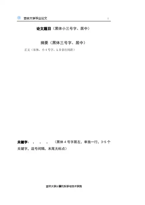
论文题目(黑体小三号字、居中)摘要(黑体三号字、居中)正文(宋体,小4号字,1.5倍行间距)关键字:,,,(黑体4号字居左,单独一行,3-5个关键字,逗号间隔,末尾无标点)英文题目(Times New Roman小三号字、居中)Author:(居右)Tutor:(居右)Abstract正文(Times New Roman ,小4号字,1.5倍行间距)Keywords:,,,(Times New Roman4号字居左,单独一行,3-5个关键字,逗号间隔,末尾无标点)目录目录 (1)第1章绪论(黑体3号、居中) (1)1.1二级标题(黑体4号、居左) (1)1.1.1三级标题(黑体小4号、居左) (1)第2章论文主体 (3)2.1二级标题 (3)2.1.1 三级标题 (3)第3章结论或论文主体(视个人情况而定) (5)3.1二级标题 (5)3.1.1 三级标题 (5)致谢 (6)参考文献 (7)注意:(成稿以后请删除)使用菜单中“插入”下的“引用”中“索引和目录”项,选择对话框中的“显示页码”和“页码右对齐”即可自动编排目录。
具体例子所示如上。
目录自动显示后,需将其中不需列出的项目删除。
第一级采用左对齐的格式,左缩进为0,下一级与之对应的上一级向右缩进0.74CM目录部分的页码采用罗马数字,宋体小4号字。
第1章绪论(黑体3号、居中)1.1 二级标题(黑体4号、居左)正文内容(正文为宋体,小4号字,1.5倍行间距,标准字符间距。
)(主要阐述选题的理论和实际意义及研究背景、文献综述、研究现状、研究思路、实验设计、采用的技术方法和手段、论文的整体结构安排等。
)1.1.1三级标题(黑体小4号、居左)1. …1)…正文中对总项包括的分项采用1.、2.、…单独序号,对分项中的小项采用的序号或数字加括号,括号后不再加其他标点。
若文中有图或表,则有如下要求:论文中的图、表、公式、算式等,均按论文章节的划分,用阿拉伯数字依序连续编号,章节号和序列号之间用“-(半角)”隔开。
吉林大学毕业设计题目:潭邵高速公路施工图设计(K0+000——K3+301.950)姓名:侯萌专业:道路桥梁工程技术本项目为潭邵高速公路施工图设计,该项目的实施将对带动该地区经济发展、方便地方人民群众生活起到积极作用;也是联系本地与外界的一条重要通道。
全线采用四车道高速公路标准:计算行车速度采用100公里/小时,路基宽度26米,桥涵设计荷载采用公路-Ⅰ级。
该段路线全场长3.302公里。
根据使用性质和任务,确定了公路的等级。
查找相应技术规范和以及设计需要的各种参数,结合地形条件在平面图中进行路线方案比选。
选择一个最佳方案进行详细技术设计,内容包括路线平、纵、横设计,路基路面设计和排水设计,桥梁设计,并完成施工图设计阶段应完成的各种图、表和设计说明书。
关键词:平、纵、横设计;路基路面;排水设计;桥梁The project for the Tan Shao Expressway Construction design,the implementation of the project will be to stimulate economic developme nt in the region,it's a Convenient place to play a positive role in p eople's life;And it's an important channel of local and outside.All use the standard four lane highway:calculating running speed of 100 km / hour,roadbed width of 26 meters,bridge design load using a level highway,the route of the 3.302 km long.According to the given service level and attribute of the highway , the highway is defined as the second-grade road. After Searching corresponding technical specifications and the parameters of the design and combining the local natural condition and through analysis and comparision of several feasible plans,the most proper one of these is recommended and subsequently carried out in detail which it includes line level, longitudinal and transverse design, pavement design,drainage design, bridge design and construction design.During the construction design phase, a variety of graphs, charts and design specifications should be completed.Keywords: line level, longitudinal and transverse design subgrade;pavement; Bridge; construction organization目录1.绪论............................................. 错误!未定义书签。
附件1吉林大学珠海学院本科毕业论文(设计)撰写规范一、内容要求(一)题目:题目应简洁、确切、有概括性,字数一般不超过20字,必要时可加副标题。
题目应有中英文对照,英文题目应与中文题目含义一致。
(二)论文摘要:论文摘要是论文内容的简要陈述,是论文主要论点、创新见解的高度概括,摘要应具有独立性和完整性。
摘要应有中英文对照,中文摘要在400字左右,外文摘要应与中文摘要相对应,要求用词准确、语法规范、意思完整。
(三)关键词:关键词是供检索用的主题词条,应采用能覆盖论文主要内容的通用技术词条(参照相应的技术术语标准)。
关键词一般列3~5个,按词条的外延层次排列(外延大的排在前面)。
关键词应有中英文对照,中、英文关键词应一一对应。
(四)目录:一般列至三级标题,要求标题层次清晰。
目录中的标题应与正文中的标题一致,并标明页码。
(五)论文正文论文正文包括前言或绪论、论文主体及结论等部分。
1、前言(绪论)。
内容应包括:本研究课题的学术背景及理论与实际意义;国内外文献综述;本研究课题的来源及主要研究内容。
2、论文主体。
论文主体是学位论文的核心部分,应该结构合理,层次清楚,重点突出,文字简练、通顺。
论文主体的内容应包括理论分析、数据资料、实验方法及结果、本人的论点、结论等内容,还要附有关图表、照片、公式等。
文中若有同指导教师或他人共同研究、试验的内容以及引用他人成果或结论的内容,必须有明确说明,不得将其与本人提出的理论分析混淆在一起。
3、结论。
结论是对整个研究工作的归纳和综合,对所得结果与已有结果的比较和课题尚存在的问题,以及进一步开展研究的见解与建议。
(六)附录:对于一些不宜放在正文中,但有参考价值的内容,可编入毕业论文(设计)的附录中,例如公式推演、源程序等。
如文章中引用的符号较多时,便于读者查阅,可以编写一个符号说明,注明符号代表的意义。
(七)参考文献:参考文献是毕业论文(设计)不可缺少的组成部分,它反映毕业论文(设计)的取材来源、材料的广博程度和材料的可靠程度,也是作者对他人知识成果的承认和尊重。
毕业论文(设计)格式参考要求1.毕业论文(设计)排版格式1.1.纸张B5(JIS);1.2.版面上边:2.5cm下边:2.0cm左边:1.5cm 右边:1.5cm页眉:1.0cm 页脚:1.0cm 装订:1.0cm;1.3.目录自动生成;1.4.文字、图表、公式等全部打印;1.5.封面和摘要单面打印(单独一张),其余双面打印;1.6.编排顺序封面、摘要、目录、正文、结论(含致谢)、参考文献1.7.章节编号采用三级标题排序一级标题为绪论、第一章、第二章、…、结论、参考文献、3号加黑宋体,居中;二级标题为1.1、1.2、…,小3号加黑宋体,顶格;三级标题为1.1.1、1.1.2、…,4号加黑宋体,顶格;1.8.正文小4号宋体;1.9.页眉正文中每页加页眉,内容与章目内容一致,5号宋体加黑,居中;1.10.页码摘要不加页码;目录用罗马数字加页码(I,II,III…,居中);正文用阿拉伯数字加页码(1,2,3…,居中);1.11.参考文献常用格式书名、作者、出版社、出版年月、起止页码几种常用文献的著录格式如下:专著:序号著者.书名.出版地:出版者,出版年月译著:序号著者.书名.译者译.出版地:出版者,出版年月期刊:序号著者.篇名.刊名,出版年,卷(期):起止页码学位论文:序号著者.篇名.保存地:保存者,授予年电子文献:序号著者.篇名.文献出处.发布日期标准文献:序号标准代码及编号—发布年,标准名称2.内容要求2.1.题目字数一般不超过20个汉字;2.2.摘要是一篇完整的短文,即正文的缩写,字数300-500。
要突出毕业论文(设计)中心内容,具有独立性和自含性;2.3.关键词 3-5个,针对标题提炼关键词,附在摘要后面;2.4.绪论主要介绍毕业论文(设计)的选题背景、意义。
说明为什么要论述这个问题,问题出现的环境和条件,解决该问题后能起什么作用。
另外,拟采用什么方法来研究这个问题;2.5.正文 8,000-10,000字,要在阅读大量文献和调研的基础上,运用辩证逻辑思维方法,对所立主题进行全面、具体、本质而科学的论证,做到主题突出,结构合理,层次分明,语言流畅,论据充分,论证有力;2.6.结论在正文之后(单占一页);其内容之一是对毕业论文(设计)的总结,突出核心;内容之二是对学院和相关人的致谢。