simulation
- 格式:pdf
- 大小:227.76 KB
- 文档页数:21


仿真是一种模拟真实系统的过程,仿真数据则是通过仿真过程产生的数据。
对于很多领域如工程、医学、科学研究等来说,仿真数据在很多时候都是非常有用的。
然而,要正确地理解和分析仿真数据并不是一件容易的事情。
在这篇文章中,我们将讨论如何正确地看懂仿真数据。
1. 了解仿真模型仿真数据是由仿真模型产生的,因此要理解仿真数据,首先需要了解仿真模型。
仿真模型是对真实系统的一种抽象和简化,它包括系统的结构、行为和动态特性等。
在理解仿真数据时,我们需要了解仿真模型的基本原理和假设条件,从而更好地理解仿真数据的产生过程和含义。
2. 确定仿真数据的类型和特征在看懂仿真数据之前,我们需要先确定仿真数据的类型和特征。
仿真数据可以是连续的时间序列数据,也可以是离散的事件数据。
仿真数据可能具有随机性和不确定性,也可能包含有周期性和趋势性。
通过对仿真数据的类型和特征进行分析,我们可以更好地选择合适的分析方法和工具,从而更准确地理解仿真数据。
3. 进行数据预处理和清洗在分析仿真数据之前,我们通常需要进行数据预处理和清洗,以确保数据的质量和可靠性。
数据预处理包括数据的去噪、缺失值处理、异常值检测和处理等。
通过数据预处理和清洗,我们可以更好地理解和分析仿真数据,避免因数据质量不佳而导致的分析错误。
4. 使用合适的分析方法和工具针对不同类型和特征的仿真数据,我们需要选择合适的分析方法和工具。
对于连续的时间序列数据,可以使用时间序列分析方法;对于具有周期性和趋势性的数据,可以使用周期性分析和趋势预测方法。
对于具有随机性和不确定性的数据,可以使用概率统计方法和模拟方法进行分析。
通过选择合适的分析方法和工具,我们可以更好地理解和分析仿真数据。
5. 结合仿真模型进行解释和验证在看懂仿真数据时,我们需要将仿真数据和仿真模型进行结合,进行数据的解释和验证。
通过将仿真数据和仿真模型进行对比和分析,我们可以更准确地理解仿真数据的含义和产生过程,从而验证仿真模型的准确性和有效性。
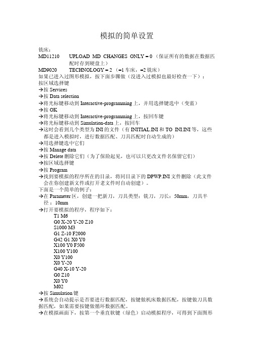
模拟的简单设置铣床:MD11210 UPLOAD_MD_CHANGES_ONLY = 0 (保证所有的数据在数据匹配时存到硬盘上)MD9020 TECHNOLOGY = 2 (=1车床,=2铣床)如果已进入过图形模拟,按下面步骤做(没进入过模拟也最好检查一下):按区域选择键Æ按ServicesÆ按Data selectionÆ将光标键移动到Interactive-programming上,并用选择键选中(变蓝)Æ按OKÆ将光标键移动到Interactive-programming上,按回车键Æ将光标键移动到Simulation-data上,按回车Æ这时会看到几个类型为INI的文件(有INITIAL.INI和TO_INI.INI等,这些都是进入模拟时,进行数据匹配、刀具匹配时自动生成的)Æ用选择键选中它们Æ按Manage dataÆ按Delete删除它们(为了保险起见,也可以只更改文件名保留它们)Æ按区域选择键Æ按ProgramÆ找到要模拟的程序所在的目录,将同目录下的DPWP.INI文件删除(此文件会在你创建新文件或打开老文件时自动创建)。
下面是一个简单的例子:Æ在Parameter区,创建一把新刀,刀具类型:铣刀,刀长:50mm,刀具半 径:10mmÆ打开要模拟的程序,程序如下:M6T1G0 X-20 Y-20 Z10M3S1000G1 Z-10 F2000G42 G1 X0 Y0X100 Y0 F500Y100X100Y100X0Y-20X0G40 X-10 Y-20G0Z10Y0X0M02Æ按Simulation键Æ系统会自动提示是否要进行数据匹配,按键做机床数据匹配,按键做刀具数据匹配,如果需要按键做循环数据匹配。
Æ在模拟画面下,按第一个垂直软键(绿色)启动模拟程序,可得到下面图形车床:MD11210 UPLOAD_MD_CHANGES_ONLY = 0 (保证所有的数据在数据匹配时存到硬盘上)1(=1车床,=2铣床)=MD9020 TECHNOLOGY如果已进入过图形模拟,按下面步骤做(没进入过模拟也最好检查一下):按区域选择键Æ按ServicesÆ按Data selectionÆ将光标键移动到Interactive-programming上,并用选择键选中(变蓝)Æ按OKÆ将光标键移动到Interactive-programming上,按回车键Æ将光标键移动到Simulation-data上,按回车Æ这时会看到几个类型为INI的文件(有INITIAL.INI和TO_INI.INI等,这些都是进入模拟时,进行数据匹配、刀具匹配时自动生成的)Æ用选择键选中它们Æ按Manage dataÆ按Delete删除它们(为了保险起见,也可以只更改文件名保留它们)Æ按区域选择键Æ按ProgramÆ找到要模拟的程序所在的目录,将同目录下的DPWP.INI文件删除(此文件会在你创建新文件或打开老文件时自动创建)。

SolidWorksSimulation图解应用教程(一)SolidWorksSimulation图解应用教程(一)SolidWorksSimulation是一款非常强大的仿真软件,可以用于进行结构力学仿真、流体力学仿真、热力仿真等多种仿真分析。
在本教程中,我们将介绍如何使用SolidWorksSimulation进行结构力学仿真。
首先,打开SolidWorks软件,并创建一个新的零件文件。
然后,在菜单栏中选择“仿真”选项,并点击“新建仿真”按钮。
这样就可以进入SolidWorksSimulation的仿真界面。
在仿真界面中,可以看到左侧的工具栏,其中包含了各种不同的仿真分析选项。
我们先来介绍一下结构力学仿真。
在SolidWorksSimulation中进行结构力学仿真分析时,首先需要定义材料属性和加载条件。
在工具栏中选择“材料法线”,然后点击零件上的表面,就可以定义该零件的材料属性。
接下来,我们需要定义加载条件。
在工具栏中选择“边界条件”,然后点击零件上需要加载的边界,例如固定约束或者力加载。
通过定义边界条件,可以使仿真结果更加准确。
在完成材料属性和加载条件的定义后,我们可以进行网格划分。
网格划分非常重要,它可以影响仿真结果的准确性和计算速度。
在工具栏中选择“自动网格”或者“手动网格”选项,然后点击零件进行网格划分。
完成网格划分后,就可以进行仿真计算了。
在工具栏中选择“运行仿真”,然后选择仿真类型和设置仿真参数,最后点击计算按钮进行仿真计算。
在仿真计算完成后,可以查看仿真结果。
在工具栏中选择“结果”选项,然后点击“位移”、“应力”或者“因子安全系数”等选项,就可以查看相应的仿真结果。
需要注意的是,SolidWorksSimulation并不是万能的,它只能在一定的条件下对零件进行仿真分析。
因此,在使用SolidWorksSimulation 进行仿真时,需要根据具体情况和需求选择合适的仿真方法和设置。
SolidWorks_Simulation教程SolidWorks是一种三维CAD软件,可以用于设计和模拟物理系统。
SolidWorks Simulation是SolidWorks的一个模块,它可以用于进行结构、流体和热传递等各种仿真分析。
本教程将介绍SolidWorksSimulation的基本使用方法。
1. 启动SolidWorks并创建一个新的部件文档。
选择适当的模板,例如“英制部件”。
2. 在新建部件中,选择“评估”选项卡,然后选择“模拟Xpress”。
3.在弹出的窗口中,选择要进行的仿真类型,例如“静态仿真”。
4.在仿真设置向导中,定义要仿真的材料属性。
可以选择现有材料库中的材料,也可以定义新的材料。
6.在“区域”页上,定义要进行仿真的区域。
这可以是整个部件或特定的几何区域。
8.完成设置后,单击“运行仿真”按钮开始仿真分析。
9.在仿真运行完成后,可以查看仿真结果。
选择“报告”选项卡上的“结果”按钮。
这将显示不同的结果图,例如位移、应力、应变等。
10.根据需要进行结果分析。
可以选择并查看不同的结果图,调整显示参数,比较不同的设计方案等。
11. 如果需要修改部件的设计,则可以返回到SolidWorks中进行修改。
然后再次运行仿真以验证更改后的设计。
12.导出结果。
可以导出仿真结果以便进一步分析或与他人共享。
选择“文件”选项卡上的“导出图像”或“导出3D图形”按钮来导出结果。
总的来说,SolidWorks Simulation是一款强大的工具,可以帮助设计师分析和优化他们的设计。
通过本教程,您应该能够了解SolidWorks Simulation的基本使用方法,并开始进行各种仿真分析。
但请注意,这只是起点,深入了解和应用SolidWorks Simulation需要更多的实践和学习。
simulation翻译simulation翻译为模拟。
用法:模拟是指使用计算机程序或其他工具来模仿真实世界的过程或事件,以便研究或预测其行为和结果。
它在许多领域都有广泛的应用,包括科学、工程、经济、医学等。
双语例句:1. The engineers are using simulation to test the durability of the new bridge design.工程师们正在使用模拟来测试新的桥梁设计的耐久性。
2. The flight simulator provides a realistic simulation of flying an aircraft.飞行模拟器提供了一个真实的飞行体验。
3. The computer simulation of weather patterns can help meteorologists predict future weather conditions.气象模式的计算机模拟可以帮助气象学家预测未来的天气情况。
4. The virtual reality simulation allows surgeons to practice complex procedures before performing them on real patients.虚拟现实模拟允许外科医生在操作真实患者之前练习复杂的手术程序。
5. The simulation of traffic flow helps urban planners analyze and improve transportation systems.交通流模拟可以帮助城市规划者分析和改进交通系统。
6. The simulation of chemical reactions in a lab can save time and resources compared to conducting physical experiments.与进行物理实验相比,实验室化学反应的模拟可以节省时间和资源。
在编程中,simulation通常指的是模拟,即通过计算机程序来模拟某个系统或现象的行为。
这种模拟可以在各种领域中使用,例如物理学、经济学、生物学等。
在物理学中,模拟可以用来模拟物理系统的运动和变化,例如行星的运动、气体分子的运动等。
在经济学中,模拟可以用来预测市场趋势、模拟经济系统的行为等。
在生物学中,模拟可以用来模拟生物体的行为和进化等。
使用模拟需要先建立数学模型或物理模型,然后使用计算机程序来实现这些模型。
模拟通常需要使用数学和物理学的知识,以及对计算机程序设计和数据分析的理解。
模拟在许多领域中都有应用,例如游戏开发、电影制作、军事仿真等。
此外,模拟还可以用于教育、研究和开发中,例如用于研究新的算法或技术、测试新的系统或设备等。
TERTS, a generic real-time gas turbine simulation environmentW.P.J. Visser, M.J. Broomhead and J. van der VorstNationaal Nationaal Lucht- en Lucht- en Lucht- en Ruimtevaartlaboratorium Ruimtevaartlaboratorium National Aerospace Laboratory NLRNLR-TP-2002-069TERTS, a generic real-time gas turbinesimulation environmentW.P.J. Visser, M.J. Broomhead and J. van der VorstThis report is based on a presentation held at the ASME IGTI TurboExpo 2001,New Orleans, June 4-7, 2001 and has also been published as ASME-2001-GT-446.The contents of this report may be cited on condition that full credit is given to NLR and the authorsCustomer:National Aerospace Laboratory NLRWorking Plan number: V.2.A.3Owner:National Aerospace Laboratory NLRDivision:FlightDistribution:UnlimitedClassification title:UnclassifiedFebruary 2002SummaryReal-time simulation of gas turbine engine performance is used in a variety of aerospace applications. For simulation of propulsion system performance in flight-simulators, fidelity requirements become increasingly stringent. Significant improvements in simulation fidelity can be obtained when using thermodynamic models instead of the customary (piece-wise) linear real-time models. However, real-time thermodynamic models require sophisticated methods to efficiently solve the model equations on a real-time basis with sufficient speed.NLR has developed the ‘Turbine Engine Real-Time Simulator’ (TERTS) generic real-time engine simulation environment for full thermodynamic simulation of various gas turbine engine configurations. At NLR’s National Simulation Facility (NSF1), research is performed on pilot-in-the-loop simulation of complex aircraft and helicopter configurations such as thrust-vectoring and Integrated Flight Propulsion Control (IFPC) concepts. For this application, high-fidelity real-time gas turbine models are required. TERTS has an efficient method for solving the engine model equations real-time. The system is implemented in Matlab-Simulink£, which offers advantages in terms of control system modeling flexibility. With TERTS, detailed thermodynamic real-time engine models can easily be implemented in NSF providing an excellent means to analyze a variety of engine effects on pilot-in-the-loop aircraft performance. In this paper the TERTS modeling environment is described including the numerical solutions used to comply with the real-time requirements. A TERTS model of a military afterburning turbofan is presented including simulation results.1http://www.nlr.nl/public/facilities/f115-03/index.htmlContents1Introduction42Real-time gas turbine simulation methods53TERTS Model description73.1Numerical method73.2Stability83.3Accuracy93.4Architecture93.5User interface103.6Component models11 4Applications135Twin-spool afterburning turbofan model145.1Validation145.2Transient performance175.3Real-time execution speed18 6Conclusions19 References20(20 pages in total)1IntroductionNLR’s ‘Turbine Engine Real-Time Simulator’ (TERTS) is a component-based real-time modeling environment for gas turbines. With TERTS, full thermodynamic models of any kind of gas turbine configuration can be developed by establishing specific arrangements of engine component models in a model window.TERTS is a powerful real-time tool for analysis of effects of malfunctions of control systems and other sub-systems on performance in pilot-in-the-loop simulations.Since NLR is presented with a wide variety of gas turbine performance problems, simulation tools with a high degree of flexibility are required. As with NLR’s Gas turbine Simulation Program GSP [1], TERTS was developed to allow rapid adaptation to various configurations, rather than being dedicated to a specific engine.TERTS is implemented in the Matlab-Simulink2 environment, offering excellent means to develop separate component and subsystem (especially control system) models. From Simulink, C-code can be generated for direct implementation of the model in the NSF simulation environment.2Copyright © The MathWorks, Inc.2Real-time gas turbine simulation methodsWith transient simulation, off-line models may accept undefined calculation times for iteration towards a transient operating point solution in a single time step. However, real-time models must employ special numerical methods to guarantee sufficient convergence at every time step within a predefined execution time.Customary methodology of real-time gas turbine simulation is creating linear models obtained from system identification. Often ‘piece wise’ linear models are used where a series of separate linear models is used to cover the highly non-linear state space. Separate linear models are then determined for separate operating conditions (e.g. rotor speeds). This method is widely applied for flight simulators and control system design [2,3]. However, since this method is principally empirical, all operating condition effects on performance (such as failures, installation losses and deterioration) need to be implemented explicitly. For analysis of every new effect, additional code needs to be developed. Especially for research purposes where a large variety of effects is analyzed, this is unpractical.Thus, instead of empirical models, higher-fidelity physical (thermodynamic) models are required in which most effects on performance are implicitly included in the model equations. These optimally are real-time derivatives of the customary 0-D component based engine models such as GSP [1] in which the equations for the conservation of mass, energy and momentum are solved for each component.These models may use several methods to solve the non-linear set of equations representing a valid (quasi steady state) engine operating point during a transient [4,5]. Often, a Jacobian matrix is used to represent a linearized model (the sensitivity of the equation errors to the state deviations) in a particular operating point. The solver methods include Newton-Raphson based schemes [6], the Broyden Jacobian update method [7], and also different transient integration methods.During iteration, new inverse Jacobians need to be determined to represent successive linearized models used to iterate towards the solution, due to the highly non-linear nature of a gas turbine system. Many pitfalls exist that can prevent successful solution, such as oscillation around the solution, ill-conditioned or singular Jacobians or dwelling in areas in the state space where most of the equation errors have a minimum. Stable, reliable convergence is hard to obtain, especially with generic engine simulation systems, where engine specific ‘fixes’ cannot be used.The requirement of a limited execution time per time step for real-time simulation introduces an additional problem, since the execution time for the iteration is unknown in advance. A general approach here is “truncated iteration”: after a limited number of iteration steps (within maximum execution time per time step) the iteration is stopped and the accuracy accepted. It is assumed that succeeding time step iterations will further reduce any inaccuracies. This assumption is reasonable if the engine simulation involves high transient rates only at short intervals. In between where the engine runs “relatively steady”, any remaining errors in the equations are eliminated. This is normally the case, even with rather “violent” aircraft gas turbine operation.Still, truncated iteration with re-determination of Jacobians during the simulation remains risky in unknown operating conditions. Extensive testing in all possible modes of operation is required to determine accuracy and execution speed requirements. Especially with complex thermodynamic engine models, the operating conditions are determined by so many variables that all combinations can never fully be tested.3 TERTS Model description3.1 Numerical methodWith TERTS, the approach to avoid recalculation of inverse Jacobians during simulation is applied. It was recognized that a single inverse Jacobian is able to represent engine behavior in a limited part of the operating envelope, implying that a multiple of inverse Jacobians could represent the entire envelope. With many different variables defining the operating envelope however, this would be unpractical. An attempt was made to find a limited set of variables able to represent the engine envelope using dimensionless and reduced engine parameters.Analysis of the inverse Jacobian indicated that corrected gas generator speed is the main factor responsible for deviations in the inverse Jacobian. This only applies if the Jacobian is determined for dimensionless and normalized state parameters. For a fixed corrected gas generator speed level, engine operation may well be simulated using a single Jacobian inverse (i.e. a single linear model, sufficiently able to provide convergence to various non-linear operating points). This would mean the entire operating envelope can be covered with a series of inverse Jacobians 1−J as a function of corrected gas generator speed ggc N :)(1ggc N F J =−For a real-time simulation this would entail pre-calculation and storage of an array of inverse Jacobians, while during simulation an inverse Jacobian is obtained by interpolation with gas generator speed. Hence, no inverse Jacobians need to be recalculated. To minimize the equation errors E , one or more iteration steps per time step i can be performed for the states S using the interpolated inverse Jacobians:i i i E J S S .11−+−=, i=1…If time step size is small enough (see section Stability), explicit Euler integration can be used:tt t t S t S S »¼º«¬ª∂∂∆+=+.1An important observation with gas turbine simulation is that rotor inertia is a major factor determining transient performance. The high frequency dynamics of thermodynamic states in the components (pressures, temperatures, flows etc.) only have small effects on rotor dynamics.This means the rotor speed dynamics can be ‘de-coupled’ from the component thermodynamics:with the explicit Euler integration, rotor speed states can be updated using the spool power errors for acceleration. The iteration updating the state at each time step therefore does not need to be applied to the rotor speed states. With a turbojet for example, 4 states and 4 errors would suffice to describe the engine system: one state represents rotor speed and therefore only 3 states need updating, requiring a 3x3 Jacobian.Another issue is the limitation of the state update. With accurate off-line models where new Jacobians occasionally need to be re-determined and inverted repeatedly during single time steps, the state change often is limited for the linearization to remain valid. With single iterations per (small) time steps this limitation is unnecessary: the test models showed that best results (i.e. lowest equation errors and high stability) were obtained with state updates based on the full (unlimited) result of the product of 1−J and the error vector E.3.2StabilityThe stability of a TERTS model can be assessed using eigenvalues of the non-linear system. Real eigenvalues show state variables inhibiting first order behavior, while complex eigenvalues refer to at least second order responses of state variables. A stable system has eigenvalues with only negative real parts. Linearizing the non-linear system around an equilibrium point (a standard function in Matlab) allows determination of the eigenvalues. For a range of steady state operating points determined in advance, the stability of the system for small disturbances in input can be obtained. Figure 1 for example indicates the stability of a turboshaft engine model.Figure 1 : Eigenvalue analysis exampleWith the explicit Euler method, time step size must be minimized in order to obtain maximum stability [6]. This implies a single iteration step per time step, as was found from test runs evaluating different iteration/integration schemes.Some simple models were developed to test stability of the concept including a turbojet and a turboshaft. To improve the solver iteration stability, states and errors have been normalized. Best results were obtained with a single iteration step (state update) per integration time step at the smallest time step. At least 0.0333 (30Hz) is required to keep equation errors below 5%.With more complex models, the time step requirements become more stringent: with the AB Turbofan model, at least 60 Hz is required to maintain accuracy with the afterburner control modeling. Figure 6 shows the equation errors during slam accels / decels. Stability was maintained at all conditions tested while the equation errors remained below 2% in most cases.With more computing power available, the best way to increase accuracy and stability is to just reduce time step size.3.3 AccuracyBoth the equation errors and deviations of the thermodynamic model from known data affect accuracy of the simulation results. The previous section showed that the equation errors can be minimized by applying small time steps. Even if optimally tuned, the thermodynamic model has limitations in the 0-D component models. During (the quasi-steady state simulated) transients,the steady state component maps may not accurately represent component performance. If detailed control system simulations are involved, simulation time step size should correspond to (be at least smaller than) the smallest control update time step.In some cases convergence (rate at which the equation errors disappear) is relatively slow, even during stable steady state. This is due to deviation of the Jacobian from the actual linear model in the particular operating point. In the example application at the end of this paper this is visible at IDLE power (Figure 6): the errors stay in the order of 1% for several seconds.Although this is sufficient for most applications, adding dimensions in the inverse Jacobian function for more precise representation of the entire state space can further improve convergence. This may well be required for simulations of particular failure effects,significantly affecting component performance. Adding T4/T2 (TIT over inlet temperature) as parameter representing the gas generator load would be the next step in this direction. Then the equation for 1−J would change into:)2/4,(1T T N F J ggc =−Additional errors in the thermodynamic model can be evaluated by comparing steady state performance results and errors minimized by fine-tuning the model. Finally, evaluation is required for transient performance, although often only limited transient data are available. In the AB Turbofan application example some validation data will be given.3.4 ArchitectureTERTS models are composed of configurations of component models similar to off-line 0-D gas turbine cycle models. Off-design transient gas turbine performance is calculated, relative to a reference operating report, usually the design point.Matlab-Simulink offers the ability to decompose complex systems into smaller functional subsystems. A basic similarity between TERTS and GSP is therefore applicable and used to derive TERTS models from GSP. However, of the three object-oriented principles (encapsulation, inheritance and polymorphism), only encapsulation is supported by Matlab-Simulink.3.5User interfaceTERTS employs the Simulink graphical user interface and reflects the component-based architecture for the gas turbine model. The main window manages the top-level model (Figure 2) and simulation, while lower level models (Figure 3) are accessed by zooming in on a system through double-clicking.Input is provided in files listing input variables, off-design component maps, control schedules, etc. These files are simply accessed by any text file editor. Using scalable maps and control functions and dimensionless parameters, most component models are generic.Figure 2 : TERTS top-level model of an afterburning turbofanMatlab-Simulink’s powerful graphical output features enable efficient presentation of results in many forms (see Figure 6 through Figure 9).3.6Component modelsCalculation is performed on component level, using relations between component entry and exit gas properties based on component maps and thermodynamic equations. All component models are non-dimensional.Figure 3 : TERTS afterburning turbofan - thermodynamic model levelTo enable real-time simulation, any component detail not having a significant effect on operation or response of the system may be eliminated. Therefore, gas path component models generally do not include volume dynamics or heat soakage effects and for thermodynamics a “quasi steady state” method is applied. Exceptions are large volumes such as afterburners: the application example indicates volume effects are significant during AB light-up for example where relative large equation errors emerge (see section Validation, Figure 6).The component models allow for simulation of secondary airflows, turbine cooling and variable (compressor) geometry if required for higher fidelity or accuracy. This often applies to high-performance engines where large turbine cooling flows have a significant effect on performance.All components are modelled using the GSP [1] algorithms, except for the turbine, which employs:• a simplified efficiency model based on a parabolic function of the loading parameter ∆H/U2,• a rotor speed independent flow capacity map (function of pressure ratio only) .If higher fidelity is required (volume and heat soakage effects, turbine model etc.), component models can easily be adapted at the cost of execution speed but without affecting the overall simulation concept.4ApplicationsTERTS has been used in several applications:•The T700 turboshaft engine model [8]•The EUROPA (European Rotorcraft Performance Analysis) tool, a common European helicopter performance prediction computer program [9]. The EUROPA code determines the dynamic performance of helicopters by simulating maneuvers, such as offshore platform takeoffs and landings. By simulating engine failures at the most critical time during the maneuver, the helicopter’s safe maximum operating mass can be determined. A TERTS model of a small Allison 250 class turboshaft has been implemented in EUROPA.•An afterburning turbofan engine model including detailed control system models. This more complex model is selected for demonstration of TERTS in the next section.5Twin-spool afterburning turbofan modelThe engine used in this example is a twin-spool, afterburning turbofan with a low bypass ratio, a maximum thrust of approximately 110 kN and an overall pressure ratio of 25. Separate models are added for the electronic engine control (DEEC), the nozzle control and actuation, and the afterburner fuel control (Figure 2). Figure 3 shows the model one level deeper: i.e. the thermodynamic model that obtains inlet conditions and fuel flow from the top-level model. Many more sublevels exist for detailed simulation of components and subsystems.In TERTS, a twin-spool afterburning turbofan engine model employs 8 states and 8 errors:8 state variables representing:•S N2gas generator speed state•S N1fan speed state•S ML,3compressor pressure ratio state•S PR,hpt high pressure turbine pressure ratio state•S m2c inlet flow state•S ML,fan fan state•S PR,lpt low pressure turbine pressure ratio state•S BPR bypass ratio state8 error variables calculated from:•Fan entry corrected flow and map corrected flow•Compressor entry corrected flow and map corrected flow•HPT HPT power and compressor power•HPT entry corrected flow and map corrected flow•LPT LPT power and fan power•LPT entry corrected flow and map corrected flow•Mixer duct-to-core static pressure ratio(for conservation of momentum, constant duct-to-core entry flow static pressure ratio is assumed)•Nozzle entry flow and exit flow5.1ValidationSteady state performance of the model was evaluated using engine manufacturer installed performance data (N1, N2, thrust and fuel flow across the entire flight envelope).Figure 4 shows one of the validations at MIL power. In the relevant part of the flight envelope the errors remain within a 5% margin (beyond Mach 1.2 @ 0 ft, a large deviation occurs due to omission in the model of special control laws in that region).Figure 4 : Validation of steady state fuel flow at MIL powerInaccuracies in the order of 5% were accepted at this stage, since the focus was put on a demonstration of the modeling concept. With additional fine-tuning using more engine data (obtained from off-line GSP models) the accuracy can be improved (see Accuracy section).Figure 5 : Validation of net thrust at all throttle settingsTERTS determined thrust was also compared with steady state reference data during a test session in the NSF to assess inaccuracy during a typical F-16 mission simulation. The thrust-time history is displayed in Figure 5. Since the altitudes during the test session did not exactly match the reference data altitudes, the reference thrust data have been corrected for differences in pressure altitude. Results indicate a match well within 5% inaccuracy.The oscillations in the thrust curve are the result of imperfections in implementation of afterburner permission control, which have been corrected after the test session.Figure 6 : AB turbofan equation errors during accel/decelFigure 6 shows the response of the equation errors during slam decels and accels, also indicating the stability of the model. The errors remain within 4%, also during the accels. During stabilizing intermediate periods, the errors remain within 2%. During AB segment light-ups the exhaust mass flow error briefly exceeds 10%, which is corrected after a single time step and does not affect the performance parameter responses significantly as can be seen in FigureFigure 7 : Transient response exampleDuring IDLE (2–8 s), convergence (although complete and fully stable) is rather slow (Figure 6: visible errors between 2-6 s). This effect is due to the limitations of the pre-calculated Jacobianapproach and can be reduced by adding more dimensions to the inverse Jacobian function (see section Accuracy).5.2Transient performanceTransient performance has not been evaluated with test bed data at this stage. However, transient performance was found to correspond sufficiently with GSP calculated transients and with the test pilot experience in the NSF in all regions of the flight and engine power setting envelope.Figure 8 : MIL to MAX-AB thrust responseFigure 8 shows transient thrust response results for a MIL to MAX-AB slam accel (at ISA Static). The thrust shows the typical peaks at subsequent AB segment light-ups. These thrust peaks correspond to undesired pressure peaks that may cause fan stall. In practice, these must be avoided by adjusting the timing of change in exhaust nozzle position.Figure 9 shows an IDLE - MAX-AB transient response (at ISA Static) of the fan rotational speed N1 and compressor rotational speed N2. Again the afterburner segment light-ups are visible through the effects of the pressure peaks on the fan rotational speed N1.More validation work needs to be done to improve accuracy of both steady state and transient performance of the AB turbofan model. Apart from fine-tuning the present model, this may involve extending fidelity of component models (control system models, afterburner volume dynamics). This task can be performed using the existing TERTS component model library.Figure 9 : IDLE to MAX-AB engine N1 and N2 response5.3Real-time execution speedUsing Matlab-Simulink’s C-code generator, the AB turbofan model described was implemented in the NSF flight-simulator and used for Integrated Flight Propulsion Control (IFPC) and pilot-in-the-loop thrust vectoring concept research. For this purpose, flight control logic was integrated with engine control (not covered in this paper). At 100Hz (0.01s time steps), the engine model used up to about 20% of the available computing power (a 4-processor Silicon Graphics Challenge L computer, 180 Mwhetstones). Together with the aircraft model, this was well within the computing speed limitations.6ConclusionsThe TERTS real-time gas turbine simulation environment is a powerful tool for development of high-fidelity thermodynamic (gas turbine) propulsion system performance models integrated in both off-line and pilot-in-the-loop flight simulation models.The TERTS numerical method using pre-calculated inverse Jacobian functions provides high stability and accuracy, and minimizes execution time, even for complex models such as military afterburning turbofan engines.The Matlab-Simulink environment offers efficient means to create new and adapt existing models using the component-based approach and Simulink’s powerful control system modeling features.With Matlab-Simulink’s C-code generation tool, TERTS models are easily ported and embedded in aircraft modeling environments such as pilot–in-the-loop flight simulators.TERTS has been successfully demonstrated in NLR’s National Simulation Facility (NSF) as part of a project demonstrating Integrated Flight Propulsion Control (IFPC) and thrust-vectoring (TV) concepts.TERTS flexibility will prove valuable to future applications such as detailed simulations of complex STOVL/TV propulsion systems, tilt-rotor and compound helicopter propulsion systems, integrated in research flight simulators.Model inaccuracy of the current system is well within 5%. Further improvement is possible through:•Obtaining more validation data, especially transient response data.•Adding extra parameters such as T4/T2 to the inverse Jacobian function, thereby further reducing the equation errors.•Extending the level of detail of the component models (e.g. the turbine).This would require more computing power while the numerical concept can be maintained. This exercise is the subject of future research.-20-NLR-TP-2002-069References[1]Visser, W.P.J. and Broomhead M.J., 2000, “GSP, A Generic Object Oriented Gas Turbine Simulation Environment”, ASME-2000-GT-0002, also NLR-TP-2000-267[2]AIR4548 (SAE Aerospace Information Report), “Real-Time Modeling Methods for Gas Turbine Engine Performance”, 1995[3]Visser, W.P.J., 1995, “Gas Turbine Simulation at NLR, ‘Making it REAL’”, CEAS Symposium on Simulation Technology (paper MOD05), Delft, the Netherlands, also NLR-TP-95-574-L[4]French, M.W., 1982, “Development of a Compact Real-Time Turbofan Engine Dynamic Simulation”, SAE paper 821401[5]Ballin, M.G., 1988, “A High Fidelity Real-Time Simulation of a Small Turboshaft Engine”, NASA TM-100991[6]Sellers, J.F., Daniele, C.J., 1975, “DYNGEN – A Program for Calculating Steady state and Transient Performance of Turbojet and Turbofan Engines”, NASA TN D-7901[7]Broyden, C.G., 1966, “Quasi Newton Raphson Methods and their Application to Function Minimization”.[8]van Oosterhout, W.W.P.J., 1996, “Development of the Generic Thermodynamic Turboshaft Engine Real-Time Simulation (TERTS) Model”, Delft Technical University, Faculty of Aerospace, thesis report, Delft 1996, also NLR Memorandum VH-96-007[9]RESPECT, 2000, “RESPECT - Rotorcraft Efficient and Safe Procedures for Critical Trajectories”, http://www.nlr.nl/public/hosted-sites/respect/index.html。