斯派莎克教材蒸汽输送系统
- 格式:ppt
- 大小:3.55 MB
- 文档页数:28


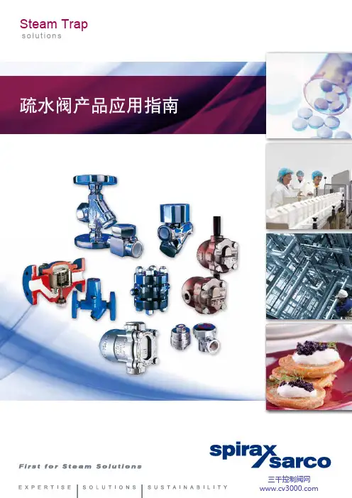
疏水阀产品应用指南Steam Traps o l u t i o n s● 我们的子公司、办事处及授权经销商遍布全世界100多个国家和地区●35个培训中心与您分享知识产品可持续发展(Sustainability)斯派莎克将致力于为客户管理好您的蒸汽系统,提供全面的能源审计,或是为您的质量、业务或生产方面的问题提供全套产品和服务,满足您的可持续发展目标。
专业技术(Expertise)斯派莎克的专业知识和技能源于100多年来的全球蒸汽工程应用经验。
这些知识和技能通过全球的35个培训中心,各种培训课程和技术出版物向客户传播。
我们所运用的专业技术是可以为客户提供的最基本而最宝贵的部分,也正是这些因素让我们与众不同,成为行业中的领先者。
斯派莎克是专业致力于推广有效的使用和控制蒸汽、热水和压缩空气等多种工业流体的节能公司。
斯派莎克在全球范围内使用专业知识和技能为广大蒸汽用户提供解决方案,从而显著提高其设备性能和系统效率,节约能源,满足您的可持续发展目标。
斯派莎克公司历史可追溯至1888年,1937年建址于英国,1959年斯派莎克集团公司在伦敦股票市场上市,每年均有骄人的业绩报告。
斯派莎克在英国、法国、德国、美国、阿根廷、巴西、意大利等国家均有生产基地,质量管理通过ISO9000体系认证,产品通过PED 认证。
解决方案(Solutions)斯派莎克作为蒸汽及热能整体解决方案提供商,我们将根据您工艺应用的具体需求,提供具有针对性的产品、系统与服务,对蒸汽和相关工艺产生的废弃物中热能的控制、再利用、回收和储存做出改造,从而达到降低您的成本,改进工艺可靠性及能效水平,帮您提高生产效率与利润。
●1000位销售工程师竭诚为您服务●100,000位长期客户遍布全球/cn斯派莎克蒸汽疏水阀斯派莎克的历史可以追溯到1888年,世界上第一台疏水阀就是由斯派莎克生产的。
经过100多年的发展,斯派莎克已经能够提供浮球型、热动力型、热静力型、双金属式和倒吊桶式等各种形式的高品质蒸汽疏水阀,至今已广泛应用在各种设备上,得到客户高度好评。
斯派莎克先导薄膜式蒸汽减压阀工作原理斯派莎克先导薄膜式蒸汽减压阀工作原理先导薄膜式蒸汽减压阀作为一种利用蒸汽自身能量来调控管系压力的自力式阀门,其性能好坏是打算整个蒸汽系统能否平安、稳定运行的关键。
由于其结构简单、工况恶劣多变且调整精度要求高,一般的静态理论计算、传统样机试验、阅历优化设计等方法根本无法满意用户对减压阀工作稳定、响应快速的运行要求。
同时随着工业生产呈现大容量、高参数、低耗的趋势进展,蒸汽减压阀内流淌诱导振动、噪声问题凸显,严峻干扰设备的稳定运行,且对操作人员的身心健康构成较大威逼。
先导式减压阀主要由先导阀和主阀组成。
先导阀作为压力调整,主阀是导阀的执行者。
二者亲密协作,完成减压过程。
任何一方消失问题,都会导致减压过程失败。
先导阀主要由导阀体,导阀芯,导阀座,导阀弹簧,调整弹簧,调整螺钉,膜片等零件组成。
先导阀的膜片可以感知阀后压力,依据阀后压力变化转变导阀芯的开启高度,掌握进口介质流到活塞上方的流量。
调整弹簧用来设定调整压力范围,转动调整螺钉可以转变出口压力。
斯派莎克先导薄膜式蒸汽减压阀工作原理主阀由阀体,活塞,活塞环,缸套,主阀芯,主阀座,主阀弹簧,底盖等零件组成。
导阀流出的介质到达活塞上方,在介质压力作用下推动活塞向下运动,带动主阀芯打开。
先导薄膜式蒸汽减压阀动态特性讨论针对以上问题,公司合作研发的先导薄膜式蒸汽减压阀系列产品中DN50、PN25规格为主体讨论对象,开展以下一系列讨论:采纳流场数值模拟方法对蒸汽减压阀不同节流阀口缩流系数和堵塞流临界压力比进行分析计算以作为数学建模依据;建立了先导薄膜式蒸汽减压阀从气源到负载完整的动态模型,其中考虑了实际工况下真实气体效应及蒸汽节流减压中的焦耳汤姆逊效应,为随后建立。
斯派莎克先导薄膜式蒸汽减压阀工作原理顺时针转动调整螺钉,压缩调整弹簧,弹簧弹性变形后,推动膜片先下动作,同时导阀芯向下动作,导阀芯开启,(介质通过主阀体内导流孔,到达导阀芯位置等候多时了)。
Steam trace heatingSpirax Sarco steam tracing systems An efficient and reliable trace heating system is a vital componentof the modern process plant. Its use ensures that optimum pumpingviscosity is maintained, product solidification or spoilage does notoccur and damage from adverse ambient conditions is avoided.No other form of trace heating offers the all round benefits of steamin terms of efficiency, low operating costs, controllability,flexibility and above all, safety.Spirax Sarco tracing system for critical applicationSpirax Sarco has provided knowledge, service and products for the control and efficient use of steam intracing systems for over 85 years. We have a wealth of experience in its use in all industries and canprovide the expertise and products to ensure that our customers enjoy its benefits.2The advantages of steam trace heating areacknowledged by experienced piping engineers and plant operators worldwide:Efficiency:Steam is the most efficient carrier of heat energy. Often, steam tracing systems can use excess process steam that would otherwise go to waste.Controllability:Precise product temperatures can be maintained and tracing can be turned on and off automatically to suit ambient conditions. Empty product lines can be pre-heated or steam cleaned without anyproblem. Increased heat demand because of insulation degradation is automatically catered for.Reliability:Steam tracing systems are extremely rugged. Their operation is not affected by adverse conditions and they easily withstand the normal day to day knocks that occur in a process plant.Flexibility:Steam tracer outputs are easily adjusted without the need to change the installation. Systems are easily extended.Safety:Steam is inherently safe and suitable for use in all zones. It is the only totally 'no risk' solution to tracing applications.Economic:Steam tracing is very simple in its concept. It is easy to design and install and uses simple mechanical components that require no external power source.Condensate InsulationSensorDiffusersReduced erosion.Reduced noise.Product line34The need for steam tracingSteam tracing is very simple in its principle of operation. When a product in a pipeline is at a higher temperature than the air surrounding it, heat will pass through the wall of the pipeline from the product to the surrounding air.This heat loss will cause the temperature of the product to fall. Insulating the pipeline will significantly lower the rate at which heat is lost, but unfortunately, no insulation is 100% efficient.Steam is a very efficient carrier of heat with a fixed relationship between its pressure and temperature. It can transport heat over long distances and gives up its heat at a constant temperature.To make up the heat lost from the product pipeline, small bore steam pipes, or tracers, are attached to the product line. Heat from the steam passes into the product line and replaces the heat lost.The amount of heat transferred, and therefore the product temperature, can easily be controlled by simple self-acting control systems. The same type of control can also be used in winterization applications, only SteamJacketed pipeline Air ventTypes of steam heat tracingWe, at Spirax Sarco, are able to provide our customers with advice and products for all types of steam tracing from simple winterization to critical jacketed applications.Jacketed - used in ultra-critical applications, usually where a product temperature has to be maintained at an elevated temperature all of the time. The use of a steam jacket also allows quick pre-heating of the pipeline.Critical - here, steam tracing is used to maintain the temperature of a product that will solidify or spoil should its temperature fall below a predetermined level.Non-critical - tracing is used to maintain the product viscosity at its optimum pumping level.Winterization - to ensure pipelines are not damaged due to freezing in adverse weather conditions.Instrument - small bore steam tracing pipes, normally 10 mm, used to protect flowmeters, control valves,sampling stations, impulse lines etc.5Determining tracer requirementsCalculating steam demandTo calculate actual steam demand, the following simple formulae can be used:-Total steam demand Individual tracer steam demandTable 1 Heat loss from insulated process pipes - W/mm =Q x L x 3.6h f g m = Q x L x 3.6h fg x n m =Steam demand (kg/h)Q =Heat loss from Table 1 (W/m)L =Length of traced product pipeline (m)h f g =Specific enthalpy of evaporation (kJ/kg)3 bar g = 2 133 kJ/kg5 bar g = 2 086 kJ/kg7 bar g = 2 048 kJ/kg9 bar g = 2 015 kJ/kgn =Number of parallel tracers per length ofproduct pipelineTo select the size and number of steam tracing lines required for a particular application, the rate of heat loss from the product pipeline under worst design conditions must be determined.This rate of heat loss is dependant upon the difference between the product temperature and the ambient temperature. Other factors such as the thermal conductivity of the insulation, ambient wind speed and the emissivity of the insulation surface will affect this rate of loss.Table 1 provides heat loss figures for insulated product pipelines up to 500 mm diameter with alternative figures for both 50 mm and 100 mm thickness insulation.The Table gives rates for an average wind speed of 10 m/s which will be suitable for most applications.Once the heat loss per metre from the insulated product pipeline is determined from Table 1, a suitable steam tracing line can be selected from Table 2. In some cases, multiple tracing lines fitted in parallel may be required.Table 2 gives practical heat transfer rates from a steam tracing line into a product line. They already take into account losses from the tracing line to the surrounding air through the insulation.The use of heat transfer cement as a fillet between the tracer and the product line will increase the rates shown in Table 2 by a factor of at least 2. It will also prevent hot spots and uneven heating.6Determining tracer requirements exampleA temperature of 100°C in a 300 mm line needs to be maintained. The minimum design ambient temperature is -15°C, steam pressure is 5 bar g and the line is 200 m long. The product line has 100 mm thick insulation with aluminium low emissivity cladding. Steam tracing lines will be steel, fitted in 50 metre lengths.Step 1 - Determine heat loss from product line1.1Temperature difference between product and ambient air = 100°C - (-15°C) = 115°C.1.2From Table 1, next temperature difference line (left scale) above 115°C is 125°C.1.3Follow 125°C temperature difference line across table until the figure for 300 mm pipe with 100 mm thick insulation is reached.1.4Read off heat loss figure - 94 W/mStep 2 - Select suitable tracer(s)2.1From Table 2, select the 100°C product temperature line from the left scale.2.2Follow the line across and read the tracer outputs from the 5 bar g column in the steel tracer section.15 mm NB tracer = 50 W/m output20 mm NB tracer = 64 W/m outputIn this instance two 15 mm NB tracers fitted in parallel will be selected to provide the 94 W/m required to make up the heat losses from the product line. Note that if heat transfer cement were used, only one 15 mm NB tracer line would be required.Spirax Sarco steam tracing productsSpirax Sarco manufacture a range of high quality products for steam tracing systems.For assistance and advice on the most suitable components for your tracing system please contact your local Spirax Sarco company.Step 3 - Calculate steam demand3.1Total steam demand 3.2Individual tracer steam demand ▲Swivel connector steam trapsSpirax Sarco manufacture a complete range of lightweight,stainless steel steam traps for tracing applications.Their rugged design ensures reliable operationunder all operating conditions.If necessary, swivel connector steam traps can be replacedvery quickly without the need to break into the tracing line.Steam distribution andcondensate collection manifoldsSpace saving forged manifolds with integral piston valveseliminate the need for on site fabrication and testing.Available in a number of configurations, all with pre-drilledmounting points.Mounting kits and insulating jackets are available to furtherease installation.▲94 W/m x 200 m x 3.6=32 kg/h 2 086 kJ/kg94 W/m x 50 m x 3.6=4kg/h2 086 kJ/kg x 27Steam trap monitoring Spiratec provides a simple and accurate method of monitoringsteam trap performance under operating conditions.It will help save energy by reporting steam traps which havefailed open and protect critical tracing applications byreporting steam traps which have failed closed.▲▲Self-acting temperature controls Simple, reliable, self-contained temperature control systems that are intrinsically safe and require no external powersource.The TA10 control range, designed specifically for tracing applications, is manufactured from stainless steel andincorporate a bellows sealed valve arrangement.▲DiffusersFitted to the outlet of steam traps or blowdown valvesdischarging to atmosphere, the Spirax Sarco diffuser greatlyreduces the problem of noise and erosion.At 1 metre the sound pressure level will be reduced by 80%.▲Pilot operated pressure reducing valvesA wide range of pressure reducing valves are availablefor applications where steam pressure needs to be reduced.Spirax Sarco pilot operated pressure reducing valveswill provide accurate control of secondary pressurewhere tracer temperature needs to be constant or must notexceed a predetermined level.▲Bellows sealed stop valves The bellows sealed stop valve is a zero emissions valveproviding long valve life with no maintenance.This robust valve is unaffected by vibration and will operateover a wide range of pressures and temperatures.CM Issue 2SB-GCM-12T R A C E Spirax-Sarco Limited, Charlton House,Cheltenham, Gloucestershire, GL53 8ER UK.T el: +44 (0)1242 521361 Fax: +44 (0)1242 573342E-mail:*************************Internet: © Copyright 2001 Spirax Sarco is a registered trademark of Spirax-Sarco LimitedA partnership with Spirax Sarco provides knowledge, service and products worldwide for the control and efficient use ofsteam and other industrial fluids.A further 46 agencies operate throughout the world.If you have difficulty finding a local contact please contact us at the number shown below.Spirax Sarco worldwide service Europe Austria Vienna Belgium Zwijnaarde Czech Republic Prague Denmark Copenhagen Finland Helsinki France Trappes Germany Konstanz Hungary Budapest Ireland Dublin Italy Milan Netherlands Maarn Norway Oslo Poland Warsaw Portugal Lisbon Russia St. Petersburg Spain Barcelona Sweden Stockholm Switzerland Zürich - Zollikon United Kingdom Cheltenham AfricaKenya Nairobi Nigeria Lagos South Africa Johannesburg l Worldwide support from a team of 3 900 dedicated employees.l Local access to Spirax Sarco's expertise and products through 39 group companies in 32 countries.l Valuable information, advice and interchange of ideas from customer training courses held in any of our 31 training centres worldwide.l A comprehensive range of the highest quality products.AmericasArgentina Buenos Aires Brazil São Paulo Canada TorontoMexico Monterrey USA Columbia, & Middle East China ShanghaiHong Konglndia Poona Indonesia Jakarta Japan Tokyo Korea SeoulU.A.E. DubaiMalaysia Kuala Lumpur Pakistan KarachiPhilippines Manila SingaporeTaiwan Taipei Thailand Bangkok Australasia Australia SydneyNew Zealand Auckland l Boiler controls l Flowmeters l Pneumatically and electronically actuatedcontrol valvesl Pressure reducing valvesl Self-acting temperature control valves l Programmable electronic controllersl Pneumatic transmitter controllers l Safety valves l Steam traps l Steam trap monitoring systems l Condensate pumps l Flash vessels l Separators l Strainers l Stop valves l Check valves l HumidifiersOur comprehensive product rangeincludes:。
蒸汽输送管道的水击及其防范马博【摘要】工业蒸汽输送管道中,水击问题始终困扰蒸汽系统运行维护人员.文章分析了蒸汽输送系统水击发生的机理及危害,并介绍如何通过有效的系统设计和布置,良好的操作实践来避免输送系统产生严重的水击事故.%In industrial steam piping, phenomenon of water hammer often makes engineers disturbed. In this article, the mechanism and harms of water hammer occurred in steam transportation system were analyzed. The methods with effective sysmematic design and arrangement and good practical operation to avoid serious accident induced from water hammer were introduced.【期刊名称】《化工设备与管道》【年(卷),期】2016(053)001【总页数】6页(P78-83)【关键词】蒸汽;管道;水击【作者】马博【作者单位】斯派莎克工程(中国)有限公司,上海 201114【正文语种】中文【中图分类】TQ050.7;TH17典型的蒸汽和冷凝水系统通常由以下四部分组成:蒸汽的产生(蒸汽锅炉或发生器),蒸汽输送管道,蒸汽使用点以及冷凝水的回收系统。
在这四大系统中,蒸汽输送管道起到连接蒸汽产生的源头和使用点,输送蒸汽的作用,根据系统规模的大小及距离的长短,输送系统的规模也不尽相同。
通常输送管道的水击发生在系统刚刚投用之初,用汽负荷由低到高突然变化[1],以及系统刚刚停运等阶段,每个过程发生的水击现象也不尽相同。
例如在系统投运以及负荷变大时,管道多阶段性地发出“咚咚”的声响;而停运后,蒸汽管道多阶段性的发出如金属敲击般的尖锐声响。