NO.1.1-HLZK-Ⅱ系列智能流量测控仪-说明书
- 格式:pdf
- 大小:2.86 MB
- 文档页数:22
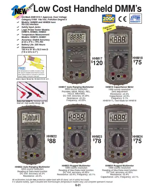
Q-21C a p ac i t a nc eM e t erHHM17 Auto-Ranging Multimeter 3999 counts resolutionProvides: MEM, READ, REL,HOLD, MAX/MINDC Volt: accuracy ±0.25%Resistance: ±0.3%Frequency: ±0.05%HHM22 Auto-Ranging Multimeter 3200 counts resolution Reading of Data-Hold function DC Volt: accuracy ±0.3%Resistance: ±0.3%HHM23 Rugged Multimeter1999 counts resolutionReading of Max/Data-Hold functionDC Volt: accuracy ±0.35%Resistance: ±0.4%; Frequency: ±0.1%HHM24 Rugged Multimeter1999 counts resolutionReading of Max/Data-Hold functionDC Volt: accuracy ±0.35%Resistance: ±0.4%Capacitance: ±2%; Frequency: ±0.1%HHM18 Capacitance Meter1999 counts resolutionZero adjustmentResistance: ±0.3%Capacitance: ±0.5%Frequency: 0.1%HHM18-TL Test leads for HHM18Low Cost Handheld DMM’sQ-22QHHM26 Auto-Ranging Multimeter 2500 counts Backlit LCD DisplayRS-232C Interfacew/Microprocessor-based DMM DCV Basic accuracy up to ±0.25%ACV Basic accuracy up to ±0.75%HHM27 Auto-Ranging Multimeter 2500 counts Backlit LCD Display Resistance accuracy up to ±0.3%w/Microprocessor-based DMM Frequency resolution up to 0.001 Hz Frequency accuracy up to ±0.05%DCV Basic accuracy up to ±0.25%ACV Basic accuracy up to ±0.75%HHM28 Auto-Ranging Multimeter 2500 counts, Backlit LCD DisplayRS-232C Interfacew/Microprocessor-based DMM Frequency resolution up to 0.001 Hz Frequency accuracy up to ±0.05%DCV Basic accuracy up to ±0.25%ACV Basic accuracy up to ±0.75%HHM19 Rugged Multimeter 1999 counts resolutionReading of Max/Data Hold functionDC Volt accuracy: ±0.35%Resistance: ±0.4%Frequency: 0.1%Comes with type K beadedthermocoupleHHM20 Auto-Ranging Multimeter 4300 counts circulating record forMax/Min/Avg. and normalProvides: AUTO-HOLD, Relative andRelative SetAuto power off to conservebattery lifeDC Volt: accuracy ±0.25%Resistance: ±0.3%HHM21 Auto-Ranging Multimeter 4300 counts circulating record forMax/Min/Avg. and normalProvides: AUTO-HOLD, Relative andRelative SetAuto power off to conserve battery lifeDC Volt: accuracy ±0.25%Resistance: ±0.3%Comes with type K beadedthermocoupleHHM19F for F°HHM19C for C°$95M e a s u r e s T e mp e r a t u r e M e a s u r e s T e mp e r a t u r e W i t h R S -232I nt e r f a c e W i t hR S -232I nt e r f a ce HHM20$100HHM21$105HHM26$113HHM27$113HHM28$138All multimeters include free protective rubber boot with tilt stand, set of safety test leads, 9 V alkaline battery, type K beaded wire thermocouple (temperature models only) and complete operator's manualALL UNITS COME WITH RUBBER BOOT AND TEST LEADSQ-23Q-24QHHM29 Rugged Multimeter4300 counts circulating record for MAX/MIN AVG and normal Provides:AUTO-HOLD, Relativeand Relative SetAuto power off to preservebattery lifeDC Volt:0-430 mV/4.3/43/430/1000 V ±0.25%AC Volt:0-430 mV/4.3/43/430/750 V±0.75~1.5% (50 Hz~20 KHz)DC current: 0-430 A/43 mA±0.5%430 mA/10 A±2%AC current:0-430 A/43 mA ±1% 430 mA/10A±2.5%Resistance:0-430 Ω/4.3/43/430 k/4300 k Ω/43 M Ω±0.3%Capacitance:0-4.3/43/430 nF/4.3 µF/430 µF±5%Inductance:0-4.3/43/430 mH/4.3/43 H ±5Frequency:430 Hz/4.3/43/430 kHz ±1%Temperature:-20~1370°C -4~2372°F ±2~3%Comes with beaded type Kthermocouple Diode test function Continuity: < 50 Ω1000 Vdc/750 Vac overload protection500 V overload protection in Diode,Ohm, Hz, Continuity Logic probe testerHHM15 Rugged Multimeter33⁄4digits 3999 counts DC Vol t: 0-400 mV/4/40/400/1000 V ±0.5%AC Volt:0-400 mV/4/40/400/750V ±1.5%DC current:0-40 m/400 mA/10 A ±1.5%AC current:0-40 m/400 mA/10 A ±2.0%Resistance: 0-400 Ω/4/40/400/4000 k Ω/40 M Ω/4000 m Ω±1%Capacitance: 0-4 nF/40 nF/400 nF/4µF/400 µF ±5%Inductance:0-4 m/40 mH/400 mH/4 H/40 H ±5%Frequency:auto-rangingup to 1 MHz±0.5%Diode test function Continuity:<40 Ω±20 Ω1000 Vdc/750 Vac overload protection 500V overload protection in Diode, Ohm, Hz, ContinuityhFE test function Logic probe functionQ-25Model No.HHM11HHM12HHM13HHM26HHM27HHM28HHM17HHM18Price$79$89$49$113$113$138$120$75Display Counts 19991999320025002500250039991999Range Auto/Manual M M M A A A A M Input Impedance M Ω1101010101010Analog bargraph ••Relative ••••Logic Test Temperature C/FData/Hold•••••MAX/MIN Record •MAX/HOLD •Capacitance ••••••Frequency •••••Continuity •••••••Diode test••••••••Transistor gain (hFE)••RS-232C••Basic accuracy, % 1.2 1.2.80.250.250.250.25MAX. Resolution, µV 100010001001001010100Basic accuracy, %2220.750.750.750.75MAX. Resolution, µV 100100100100100100100Frequency Response, Hz 50-50050-50050-50050-50050-50050-50050-20K Basic accuracy, % 2.50.750.750.750.5MAX/Resolution, µA 10000.10.10.10.1Basic accuracy, % 1.5 1.5 1.5 1.0MAX. Resolution, µA 0.10.10.10.1Frequency Response 50-50050-50050-50050-500Basic accuracy, % 4.053320.5MAX. Resolution, pF 11110.1MAX. Cap., µF 2K 32m 25254020m Basic accuracy, % 1.50.30.30.30.30.3MAX/Resolution, µH 100Max. H322525254020Basic accuracy, % 1.5 1.5 1.50.30.30.30.30.3Max. Resolution, m Ω10010010010010010010010Max. m Ω22000322525254020Basic accuracy, %.5 1.50.050.050.050.1Max. Resolution, Hz 1.00.0010.0010.0110Max Frequency, MHz 100K 55700K 15Basic accuracy, %3MAX. Resolution 1°C/°F Range °F -4~752Range °C-20~400F E A T U R EDCV ACV DCA ACA CX LX ⍀Hz C°/F°Q-26QHHM22HHM23HHM19C HHM19F HHM24HHM20HHM21HHM15HHM14HHM29HHM16HHM30$88$78$95$95$75$100$105$113$136$138$98$1203200199919991999199943004300399919999430043001999A M M M M A A M M A A A1010101010101010101010•••••••••°C°F°C/°F °C/°F °C/°F •••••A-HA-HA-HA-H••••••••••••••••••••••••••••••••••••••••••••••••••••••••0.250.350.350.350.350.250.250.5.050.250.25100100100100100 mV 1001001001010010011 1.5 1.5 1.50.750.75 1.5 1.00.750.751001001001001001001001001010010050-40050-50050-50050-50050-50050-2K 50-2K 50-50020K 50-2K 50-20.50.50.50.50.50.50.5 1.50.5 2.00.50.10.10.10.10.10.10.10.10.010.10.11.5 1.211 2.0 2.5 2.5 1.00.10.10.10.10.10.10.10.10.010.10.150-40050-50050-50050-50050-50050-1K50-1K 50-50050-50050-50050-1K32222552101010101010 1.00.13220202020400432000553110.140432000.30.40.40.40.40.30.3 1.00.20.30.30.3100100100100100100100100110010010322020202043434000204343200.10.10.10.10.5 1.010101010 1.00.1151515151430K22220.51°C 1°F 1°C/°F 1°C/°F 1°C/°F -4~1400-20~1370-20~1370-4~1562-20~750-4~2498-4~2498-20~850For a selection of thermocouples see Section A.Ordering Example:HHM21Auto-ranging DMM with type K thermocouple, $105.All multimeters include free protective rubber boot with tilt stand, set of safety test leads, 9 V alkaline battery, type K beaded wirethermocouple (temperature models only) and complete operator's manual.HHM29HHM15HHM14All temperature models include a free 36" type K beaded wire thermocouple with subminiature connector and wire spool caddy (one per channel)FREE!Order a Spare! Model No. SC-GG-K-30-36, $15CANADA www.omega.ca Laval(Quebec) 1-800-TC-OMEGA UNITED KINGDOM www. Manchester, England0800-488-488GERMANY www.omega.deDeckenpfronn, Germany************FRANCEwww.omega.fr Guyancourt, France088-466-342BENELUX www.omega.nl Amstelveen, NL 0800-099-33-44UNITED STATES 1-800-TC-OMEGA Stamford, CT.CZECH REPUBLIC www.omegaeng.cz Karviná, Czech Republic596-311-899TemperatureCalibrators, Connectors, General Test and MeasurementInstruments, Glass Bulb Thermometers, Handheld Instruments for Temperature Measurement, Ice Point References,Indicating Labels, Crayons, Cements and Lacquers, Infrared Temperature Measurement Instruments, Recorders Relative Humidity Measurement Instruments, RTD Probes, Elements and Assemblies, Temperature & Process Meters, Timers and Counters, Temperature and Process Controllers and Power Switching Devices, Thermistor Elements, Probes andAssemblies,Thermocouples Thermowells and Head and Well Assemblies, Transmitters, WirePressure, Strain and ForceDisplacement Transducers, Dynamic Measurement Force Sensors, Instrumentation for Pressure and Strain Measurements, Load Cells, Pressure Gauges, PressureReference Section, Pressure Switches, Pressure Transducers, Proximity Transducers, Regulators,Strain Gages, Torque Transducers, ValvespH and ConductivityConductivity Instrumentation, Dissolved OxygenHeatersBand Heaters, Cartridge Heaters, Circulation Heaters, Comfort Heaters, Controllers, Meters and SwitchingDevices, Flexible Heaters, General Test and Measurement Instruments, Heater Hook-up Wire, Heating Cable Flow and LevelAir Velocity Indicators, Doppler Flowmeters, LevelMeasurement, Magnetic Flowmeters, Mass Flowmeters,Pitot Tubes, Pumps, Rotameters, Turbine and Paddle Wheel Flowmeters, Ultrasonic Flowmeters, Valves, Variable Area Flowmeters, Vortex Shedding FlowmetersData AcquisitionAuto-Dialers and Alarm Monitoring Systems, Communication Products and Converters, Data Acquisition and Analysis Software, Data LoggersPlug-in Cards, Signal Conditioners, USB, RS232, RS485 and Parallel Port Data Acquisition Systems, Wireless Transmitters and Receivers。
±¾ÎÄÓÉÌìÀÖ²â»æÍø£¨£©ÕûÀíÌṩ昆仑A60 测量系统使用手册第一版广东科力达仪器有限公司二○一四年十月目录目录 (1)第一章概述 (3)§1.1 引言 (3)§1.2 产品功能 (3)§1.3 产品特点 (4)§1.4 配件组件 (5)第二章 A60测量系统 (8)§2.1A60主机 (8)§2.1.1 主机外型 (8)§2.1.2 底部接口 (9)§2.1.3 按键面板 (10)§2.1.4 模式查看和切换 (11)§2.1.5 工作状态 (12)§2.1.6 主机自检 (14)§2.2 手簿(S730) (15)§2.2.1 手簿介绍 (15)§2.2.2 蓝牙连接 (19)§2.2.3 数据传输 (23)§2.3 电台 (25)§2.3.1外挂电台特点 (25)§2.3.2 外挂电台外型 (26)§2.3.3 外挂电台接口及面板 (26)§2.3.4 外挂电台使用注意事项 (28)§2.3.5 内置电台 (28)§2.4 主机配件介绍 (28)§2.4.1 仪器箱 (28)§2.4.2 电池及充电器 (29)§2.4.3 差分天线 (30)§2.4.4 多用途数据线 (30)§2.4.5 其他配件 (31)第三章作业方案 (32)§3.1 静态作业 (32)§3.1.1 静态测量简介 (32)§3.1.2 作业流程 (32)§3.1.3 外业注意事项 (33)§3.1.4 GPS控制网设计原则 (33)§3.2 RTK作业(电台模式) (34)1§3.2.2 架设基准站 (34)§3.2.1 启动基准站 (35)§3.2.3 架设移动站 (36)§3.2.4 设置移动站 (36)§3.3 RTK作业(网络模式) (37)§3.3.1 基准站和移动站的架设 (37)§3.3.2 基准站和移动站的设置 (37)§3.4 天线高量取方式 (39)第四章数据传输和仪器升级 (40)§4.1 主机数据传输 (40)§4.2 仪器之星的操作 (40)§4.2.1 软件安装 (41)§4.2.2 数据导出 (41)§4.2.3 固件升级 (42)§4.2.4 参数设置 (45)§4.2.5 电台设置 (46)§4.2.6 网络设置 (47)§4.2.7 主机注册 (48)附录A A60测量系统主要技术指标 (51)附录B S730手簿技术指标 (53)附录C GDL-20电台技术指标 (54)附录D 专业术语注释 (56)附录E 联系方式 (57)附录F 科力达基站服务器IP (58)附录G A60测量系统1+1配置单 (59)2第一章概述§1.1 引言欢迎使用广东科力达仪器有限公司的GNSS产品。

Flo-Tech, PFM6 流量压力检测仪使用说明书流量压力检测仪的使用要领1. 检测仪各部名称(图1)涡轮流量计各部名称(图2)2. Flo-tech检测仪参数* 为现用检测仪(1) 检测仪使用要点本检测仪操作简单,不需要特殊练习,就可以立刻使用。
为了正确的判断试验结果,有必要事先了解测试对象的液压系统和各液压执行部件,掌握必要的资料,比如:操作压力、流量、溢流阀设定压力、液压泵的最高输出压力、液压泵的性能曲线等。
①液压软管的连接检测仪如上表所示有三种机型,其软管的连接分两种类型a、PFM6-50、PFM6-85为1英寸的PT内螺纹。
b、PFM6-200上附有1英寸PT螺纹的连接器。
90°的管接头、T型管接头、阀等距离检测仪的输入端最好在30cm以上,因为这些部件将会给流体的测量带来误差。
软管的另一侧(与被测机器连接侧)通常与连接检测仪一侧为相同连接螺母,所以当管径或螺纹不同时,请利用转接器。
②操作要领检测仪的操作是简单的,但误操作将会给检测仪或被测试机器、回路带来不良影响。
使用者在使用前请读熟本使用说明书,避免误操作,以提高测试效率。
a、转换开关通常在中央位置(OFF)测试流量时请放在(FLOW)档位测试油温时请放在(TEMP)档位测试结束后,请勿必将开关拨回到OFF位置。
干电池使用过期电压下降时,仪表(流量、温度计上的冒号:)将发生闪烁。
此时,请更换干电池。
b、认真确认软管是否已正确无误地连接在检测仪的输入、输出端。
检测仪可以并列接入高压侧,但流向若是接反则不能测量正确的流量。
c、液压回路动作前,应将加载阀反时针方向旋转打开。
d、加载阀可以用手简单地进行操作,在加压和卸压时,请缓慢地进行操作。
e、液压回路动作停止之前,要将加载阀打开,确认压力是否已降到零。
在进行多项压力测试时,每一次测试结束,也都应该将加载阀先打开,然后进行下一个项目的测试。
f、安全圆片是保护检测仪和液压机器的,测试时,请密切注意压力表的读数,使之不要超过回路的最高压力。
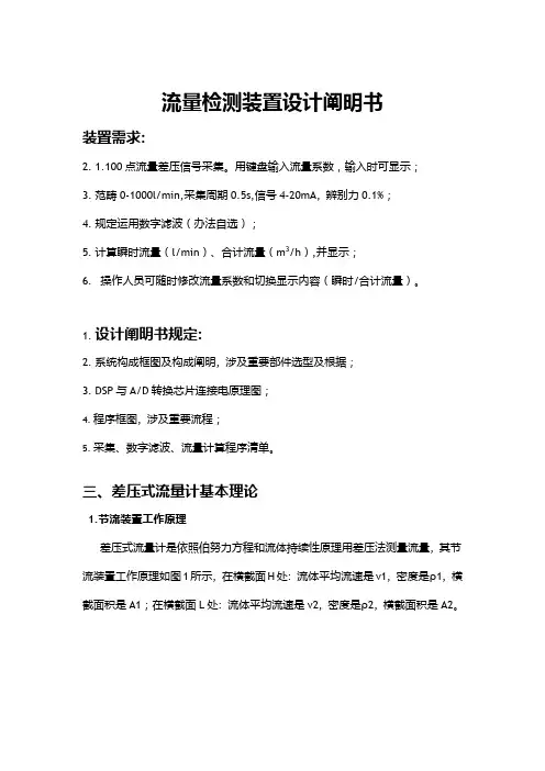
流量检测装置设计阐明书装置需求:2.1.100点流量差压信号采集。
用键盘输入流量系数,输入时可显示;3.范畴0-1000l/min,采集周期0.5s,信号4-20mA, 辨别力0.1%;4.规定运用数字滤波(办法自选);5.计算瞬时流量(l/min)、合计流量(m3/h),并显示;6.操作人员可随时修改流量系数和切换显示内容(瞬时/合计流量)。
1.设计阐明书规定:2.系统构成框图及构成阐明, 涉及重要部件选型及根据;3.DSP与A/D转换芯片连接电原理图;4.程序框图, 涉及重要流程;5.采集、数字滤波、流量计算程序清单。
三、差压式流量计基本理论1.节流装置工作原理差压式流量计是依照伯努力方程和流体持续性原理用差压法测量流量, 其节流装置工作原理如图1所示, 在横截面H处: 流体平均流速是v1, 密度是ρ1, 横截面积是A1;在横截面L处: 流体平均流速是v2, 密度是ρ2, 横截面积是A2。
图1 差压流量计工作原理图依照流体流动持续性原理有如下关系式: v 1·A 1·ρ1=v 2·A 2·ρ2 (1)如果流体是液体, 可以为在收缩前、后其密度不变:ρ1=ρ2=ρ (2)依照瞬时流量定义, 即单位时间内流体流经管道或明渠某横截面数量, 因此液体体积瞬时流量:2211A v A v q v ⋅=⋅= (3)依照伯努利方程(能量守恒定律), 在水平管道上Z1=Z2, 则有如下关系式:2222222111v P v P ρρ+=+(4)应用伯努利方程和流动持续性原理, 在两个横截面上压力差则有如下关系式:)(2212221v v P P P -=-=∆ρ(5)将(3)代入(5)式, 并整顿, 则得:22212])(1[2v A A P -=∆ρ(6)由于 , , 定义直径比 , 其中d 为工作状况下节流件等效开孔直径,D 为管道直径, 则得到:2224)1(2A q P v βρ-=∆ (7)这样可推导出如下理论流量公式:1242411ρπβPd q v ∆⋅-=(8)又由于流量系数C 定义是: C= 实际流量/理论流量, 可得出节流式差压流量计普遍合用测量体积流量实际流量公式:ρπβεPd C q v ∆⋅-⋅=24124(9)其中, ε为被测介质可膨胀性系数: 对于液体=1; 对气体、蒸气等可压缩流体<1 。
智能流量测控仪(油气连续测量装置)技术规格书山西煤层气工程技术研究所二零一九年四月1.0概述本技术规格书为油气连续计量装置的专用技术规格书,适用于山西沁水盆地煤层气中央处理厂,是对用于高压外输气体计量设备提出的最低技术要求。
油气连续计量装置的详细技术数据在相应的数据表中列出,供货商应根据本技术规格书和相应的数据表的要求向买方供货。
1.1环境山西沁水盆地煤层气中央处理厂(以下简称:中央处理厂)位于山西省晋城市境内。
其他见表1-1。
表1-1 沁水县气象指标统计表最高气温,℃ 37.4最低气温,℃ -18.7年平均气温,℃ 10.2年无霜期,天 180最大冻土深度,cm 61年最大降水量,891.2mm年平均蒸发量,1584.88mm干旱指数 1.58风力及风向 夏季多南风 最大风力10级1.2煤层气的组份表被测产品气组分表序号组分 含量(mol%)1 C1 98-992 C2 0.01-0.043 CO0.2-0.524 N0.7-1.352O 0.005-0.025 H22.0标准及规范《油气田及管道计算机控制系统设计规范》 SY/T0091《油气田及管道仪表控制系统设计规范》 SY/T0090《天然气计量系统技术要求》 GB/T 18603《用气体超声流量计测量天然气流量》 GB/T 18604以上内容仅供参考,供货商应提供在本工程中所采用的标准和规范的清单,并应保证其版本为最新版本(包括修正版)。
3.0定义·分辨率:仪表能显示的流速变化的最小程度。
·准确度:测量结果与被测量(约定)的真值之间的一致程度。
·重复性:在整个刻度范围内,并在相同操作条件和相同参比流量下,对同一被测量进行连续多次测量所得结果之间的一致性。
·复现性:在改变了的测量条件下,同一被测量的测量结果之间的一致性。
·速度采样间隔:由整套传感器或声道测得的两个相邻气体流速值之间的时间间隔,取决于仪表的尺寸,典型值为0.05s~0.5s。
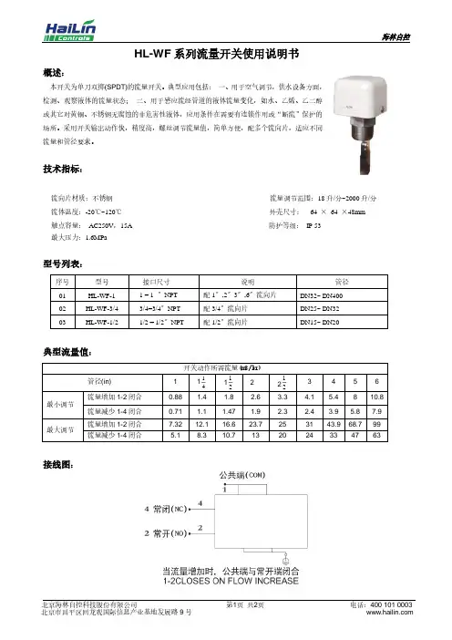
HL-WF系列流量开关使用说明书
概述:
本开关为单刀双掷(SPDT)的流量开关。
典型应用包括:一、用于空气调节,供水设备方面,
检测、观察液体的流量状态;二、用于感应流经管道的液体流量变化,如水、乙烯、乙二醇
或其它对黄铜、不锈钢无腐蚀的非危害性液体,应用条件在需要有连锁作用或“断流”保护的
场所。
采用开关输出动作快,精度高,螺丝调节流量值,简单方便,配多个流向片,适应不同
流量和管径要求。
技术指标:
流向片材质:不锈钢流量调节范围:18升/分~2000升/分流体温度:-20℃~120℃外壳尺寸:64 ×64 ×48mm 触点容量:AC250V,15A 防护等级:IP 53
最大压力:1.6MPa
型号列表:
典型流量值:
接线图:
安装与调节:
调节流量开关设定的步骤:
1、 取下HL-WF 的外壳。
2、 调高流量值,顺时针旋转调节螺丝。
在调高出厂设定值后想调低流量值,逆时针旋转调节螺丝(参见图3)。
3
、 通过按动主杠杆数次来检查流量开关的设定不低于出厂设定值。
一旦发现杠杆回复时没有“咔嗒”声,顺时针旋
转调节螺丝直到回复时有“咔嗒”声。
注意事项:
1.开关出厂设定在约为最小流量值(参见表1)。
2.不得调低于出厂设定值,因为这有可能造成开关不能回复到“无液体”的位置。
3.用于冷冻水管,此水流开关应作保温处理,防止内部冻结。
☆.不正确操作危险!由于安装/使用不当造成的零件损坏或由此引起的其它损失,不属保修范围。
此位置,用户不得随意调节
流量设定用调节螺钉(用户可调节)。
目录一、产品介绍1.概述 --------------------------------------------------------------3 2.主要技术指标 --------------------------------------------------3 二、计量仪表(二次仪表)操作说明1.键盘定义 -------------------------------------------------------4 2.计量操作 -------------------------------------------------------5 3.编程功能 -------------------------------------------------------8 三、装桶计量装置(φ40φ50)安装方法1.系统构成 --------------------------------------------------------9 2.泵的选择与安装 ----------------------------------------------10 3.流量变送器的安装 -------------------------------------------10 4.过滤器、平衡逆止阀、平衡管、表前直管段、铂电阻、胶管、油枪及油枪单向阀的安装 -------------------------10 5.装置安装注意事项 -------------------------------------------11 四、装桶计量装置(φ40φ50)的调试方法1.系统检查 -------------------------------------------------------11 2.余量计算 -------------------------------------------------------11 3.脉冲当量的测算 ----------------------------------------------12 4.密度的测算 ----------------------------------------------------12五、二次仪表的信号线及控制线的连接方法1.信号线的连接 ------------------------------------------------13 2.二次仪表控制线与交流接触器的连接 ------------------13六、装车计量装置(φ80φ100)的现场安装方法1.系统构成 -----------------------------------------------------14 2.泵的选择与安装 --------------------------------------------14 3.平衡逆止阀、平衡管的安装 -----------------------------15 4.铂电阻的安装 -----------------------------------------------16 5.流量变送器的安装 -----------------------------------------17 6.出口管道单向阀的安装 -----------------------------------17 7.装置安装注意事项 -----------------------------------------17 8.φ80卸车计量装置 -----------------------------------------17 七、安全注意事项-------------------------------------------------19 附录1 简易调整方法---------------------------------------------20 附录2 定时启动及无线遥控说明------------------------------21产品介绍1、概述YJK-II 液体流量定量控制仪是我公司自行研制生产的精度高、功能全、稳定可靠、技术领先的液体动态质量流量计量自控装置。
HLQZ型系列气体智能罗茨流量计1 概述HLQZ型系列智能气体罗茨流量计是我公司向用户提供的一种高精度、高可靠性的精密计量仪表,以其精度高、量程范围宽、体积小、重量轻、安装维修方便、使用可靠及耐久的使用寿命等特点,广泛应用于天然气、煤制气、惰性气体、空气等气体的流量计量,是国内外城市燃气、石油、化工、电力、冶金、科学研究等行业气体计量的理想配套仪表。
HLQZ系列智能罗茨流量计具有优良的低压和高压计量性能,特别适用于测量大流量气体尤其是天然气等气体的精确计量,根据用户的不同需求,我公司可提供不同精度等级、不同性能的罗茨流量计。
2 主要特征2.1 流通能力大,压损小,精度高,重复性好,量程比宽;2.2 转子、壳体经特殊表面处理,硬度高,不会轻易卡表;2.3严格的动平衡测试,确保产品的稳定性和使用寿命;2.4 使用自润滑轴承和不锈钢加油轴承,可满足客户的不同需求;2.5 流量计的智能体积修正仪可自由转动约340°,在各种安装方式下都可方便读数;2.6 采用先进的微电子技术与高性能CPU,功能强大,性能优越。
电路系统为微功耗设计,内置电池可长期供电运行,也可由外电源供电运行;2.7 集高精度温度、压力、流量传感器于一体,可检测被测气体的温度、压力和流量,并进行流量自动跟踪补偿和压缩因子的修正运算;2.8 采用液晶显示器,可显示标准累计流量、标准体积流量、工况体积流量、介质温度、压力值和电池容量百分值,并带有中英文提示符号;2.9 具有三种历史数据记录:启停记录、状态记录、日记录。
方便用户统计各种数据;2.10 具有实时数据存储功能,可防止更换电池或突然掉电时数据丢失。
在停电状态下,内部参数、历史数据记录可永久性保存;2.11 通过RS-485接口和上位机进行通讯,便于数据的集中采集和实时管理;2.12 按流量频率信号,可将仪表系数分五段自动进行线性修正,具备故障自诊断和报警功能;2.13 仪表具有防爆功能,防爆标志为ExibⅡCT4。

e-mail:**************User’s GuideFSW-119 AND FSWC1/M1/T1Flow MonitorShop online atIt is the policy of OMEGA to comply with all worldwide safety and EMC/EMI regulations that apply. OMEGA is constantly pursuing certification of its products to the European New Approach Directives. OMEGA will add the CE mark to every appropriate device upon certification.The information contained in this document is believed to be correct, but OMEGA Engineering, Inc. acceptsno liability for any errors it contains, and reserves the right to alter specifications without notice.WARNING: These products are not designed for use in, and should not be used for, human applications.Please follow these installation, connection and adjustment instructions carefully. Failure to comply with these instructions or misuse of this equipment will void your warranty.Equipment installation, connection and adjustment by qualified personnel only!iNOTES: ii1 DescriptionThis Single Point Flow Monitor is designed to monitor the flow of liquids andgases.The system is made up of monitoring head (M) with flange connector (FC),cable (C) and control unit (A), see fig. 1.Important operational safety and reliability enhancing features designed andbuilt into these units include:•Calorimetric flow monitoring, which avoids the need for moving parts in the flow stream.•The desired MIN or MAX switch point is steplessly adjustable and is clearly indicated by dual color LED (red/green).•Medium selector switch (MS) with three settings (water, oil, air).•With either no delay, or with a 60 a switch-on delay or 10 a change over delay.FCM12 Technical dataFlow rate range:Liquids10 mm/s(0.39 inch/s) minimum2 m/s(6.6 Us) maximumGases0.5 m/s(20 inch/s) minimum50 m/sIf 64 Us) maximumTemperature range:of the medium-25°C to +100°C(-13°F to +212°F)of the control unit 25°C to +50°C(-13°F to +122°F)Pressure resistanceof the monitoring head:250 bar/3675 PSIResponse delayWater approx. 2 s*Oil approx: 4 s*Air approx. 7 s** Delay with the switch point set to 1 m/s (3.3 ft./s) and the flow rateat 2 m/s (6.6 ft./s), after a sudden complete flow stoppage.Degree of protection:Monitoring head with cable IP 67Control unit IP 65Input voltage:AC 230 V (+1 0%/-1 5%)AC 115 V (+10%/-15%)AC 24 V (+1 0%/-l 5%)DC24V±10%23 Monitoring head installation1. Check that the monitoring head type is suitable for the FSW-119 for water,oil, air types -C1, -M1, -T12. For best performance the monitoring head should be installed in thepipeline in accordance with the following conditions (see fig. 2).a. The monitoring head should be installed only in a straight section ofpiping. There should be a distance of at least 10 pipe diameters before themonitoring head and 5 pipe diameters after the monitoring head before orafter any bends and changes in pipe diameter, to avoid any effects ofturbulence.3b. In the case of vertical pipelines the monitoring head should be installedwhere the flow is rising, if possible.c. For horizontal pipelines the monitoring head should be mounted on theunderside of the line (suspended)d. Avoid installing the monitoring head in known areas of high electricalinductance, capacitance, or high-frequency electromagnetic fields.If gases are the medium to be monitored, the mounting attitude ofthe monitoring head is unimportant in either vertical or horizontalpipelines.3. The monitoring head should be screwed into the pipeline far enough toensure that the sensors (S) are positioned fully in the flow stream (see fig.2). However, care should also be taken that the sensor is not screwed in toofar, thus causing an undue restriction in the pipe bore.The two sensors (S) on the monitoring head must be aligned sideby side directly across the direction of flow. The sensors arecorrectly positioned when the wrench flats (FC) are alignedparallel with the pipeline.Do not overtighten.45shown on the system.If the standard length of the monitoring head cable is insufficient,longer cables are available to order up to a maximum of 100 m(328 ft.). Use only shielded cable.1. Loosen the retaining screws and remove the cover of the housing.2. Feed the supply input cable and relay connecting cable through the appropriate cable gland.3. Connect the supply input cable to terminals 1 and 2, and the relay connecting cable to terminals 3 ... 5.4. Use cable fasteners to eliminate cable displacement.5. Plug the cable to the monitoring head and tighten with caution. Do not overtighten.6. Connect power supply.67With MAX function selected:GREEN=flow rate is below the set response value.RED=flow rate is at or above the set response value.6. To adjust the switching point, turn the flow adjustment potentiometerscrew (R) to the exact point the LED changes:MIN-function:• from GREEN to RED- turn the screw clockwise• from RED to GREEN- turn the screw counterclockwiseMAX-function:• from GREEN to RED- turn the screw counterclockwise• from RED to GREEN- turn the screw clockwiseRepeat this procedure several times to ensure correct adjustment.89NOTES: 10WARRANTY/DISCLAIMEROMEGA ENGINEERING, INC. warrants this unit to be free of defects in materials and workmanship for a period of 13 months from date of purchase. OMEGA’s Warranty adds an additional one (1) month grace period to the normal one (1) year product warranty to cover handling and shipping time. T his ensures that OMEGA’s customers receive maximum coverage on each product.If the unit malfunctions, it must be returned to the factory for evaluation. OMEGA’s Customer Service Department will issue an Authorized Return (AR) number immediately upon phone or written request. Upon examination by OMEGA, if the unit is found to be defective, it will be repaired or replaced at no charge. OMEGA’s WARRANT Y does not apply to defects resulting from any action of the purchaser, including but not limited to mishandling, improper interfacing, operation outside of design limits, improper repair, or unauthorized modification. T his WARRANTY is VOID if the unit shows evidence of having been tampered with or shows evidence of having been damaged as a result of excessive corrosion; or current, heat, moisture or vibra-tion; improper specification; misapplication; misuse or other operating conditions outside of OMEGA’s control. Components which wear are not warranted, including but not limited to contact points, fuses, and triacs.OMEGA is pleased to offer suggestions on the use of its various products. However, OMEGA neither assumes responsibility for any omissions or errors nor assumes liability for any damages that result from the use of its products in accordance with information provided by OMEGA, either verbal or written. OMEGA warrants only that the parts manufactured by it will be as specified and free of defects. OMEGA MAKES NO OTHER W ARRANTIES OR REPRESENTATIONS OF ANY KIND W HATSOEVER, EXPRESS OR IMPLIED, EXCEPT THAT OF TITLE, AND ALL IMPLIED W ARRANTIES INCLUDING ANY W ARRANTY OF MERCHANTABILITY AND FITNESS FOR A PARTICULAR PURPOSE ARE HEREBY DISCLAIMED. LIMITATION OF LIABILITY: The remedies of purchaser set forth herein are exclusive, and the total liability of OMEGA with respect to this order, whether based on contract, warranty, negligence, indemnification, strict liability or otherwise, shall not exceed the purchase price of the component upon which liability is based. In no event shall OMEGA be liable for consequential, incidental or special damages.CONDITIONS: Equipment sold by OMEGA is not intended to be used, nor shall it be used: (1) as a “Basic Component” under 10 CFR 21 (NRC), used in or with any nuclear installation or activity; or (2) in medical applications or used on humans. Should any Product(s) be used in or with any nuclear installation or activity, medical application, used on humans, or misused in any way, OMEGA assumes no responsibility as set forth in our basic WARRANTY/DISCLAIMER language, and, additionally, purchaser will indemnify OMEGA and hold OMEGA harmless from any liability or damage whatsoever arising out of the use of the Product(s) in such a manner.RETURN REQUESTS/INQUIRIESDirect all warranty and repair requests/inquiries to the OMEGA Customer Service Department. BEFORE RET URNING ANY PRODUCT(S) T O OMEGA, PURCHASER MUST OBT AIN AN AUT HORIZED RET URN (AR) NUMBER FROM OMEGA’S CUST OMER SERVICE DEPART MENT (IN ORDER T O AVOID PROCESSING DELAYS). T he assigned AR number should then be marked on the outside of the return package and on any correspondence.The purchaser is responsible for shipping charges, freight, insurance and proper packaging to prevent breakage in transit.FOR WARRANTY RETURNS, please have the following information available BEFORE contacting OMEGA:1.Purchase Order number under whichthe product was PURCHASED,2.Model and serial number of the productunder warranty, and3.Repair instructions and/or specificproblems relative to the product.FOR NON-WARRANTY REPAIRS,consult OMEGA for current repair charges. Have the following information available BEFORE contacting OMEGA:1. Purchase Order number to cover the COSTof the repair,2.Model and serial number of the product, and3.Repair instructions and/or specific problemsrelative to the product.OMEGA’s policy is to make running changes, not model changes, whenever an improvement is possible. This affords our customers the latest in technology and engineering.OMEGA is a registered trademark of OMEGA ENGINEERING, INC.© Copyright 2004 OMEGA ENGINEERING, INC. All rights reserved. This document may not be copied, photocopied, reproduced, translated, or reduced to any electronic medium or machine-readable form, in whole or in part, without the prior written consent of OMEGA ENGINEERING, INC.Where Do I Find Everything I Need for Process Measurement and Control?OMEGA…Of Course!Shop online at TEMPERATUREⅪߜThermocouple, RTD & Thermistor Probes, Connectors, Panels & AssembliesⅪߜWire: Thermocouple, RTD & ThermistorⅪߜCalibrators & Ice Point ReferencesⅪߜRecorders, Controllers & Process MonitorsⅪߜInfrared PyrometersPRESSURE, STRAIN AND FORCEⅪߜTransducers & Strain GagesⅪߜLoad Cells & Pressure GagesⅪߜDisplacement TransducersⅪߜInstrumentation & AccessoriesFLOW/LEVELⅪߜRotameters, Gas Mass Flowmeters & Flow ComputersⅪߜAir Velocity IndicatorsⅪߜTurbine/Paddlewheel SystemsⅪߜTotalizers & Batch ControllerspH/CONDUCTIVITYⅪߜpH Electrodes, Testers & AccessoriesⅪߜBenchtop/Laboratory MetersⅪߜControllers, Calibrators, Simulators & PumpsⅪߜIndustrial pH & Conductivity EquipmentDATA ACQUISITIONⅪߜData Acquisition & Engineering SoftwareⅪߜCommunications-Based Acquisition SystemsⅪߜPlug-in Cards for Apple, IBM & CompatiblesⅪߜDatalogging SystemsⅪߜRecorders, Printers & PlottersHEATERSⅪߜHeating CableⅪߜCartridge & Strip HeatersⅪߜImmersion & Band HeatersⅪߜFlexible HeatersⅪߜLaboratory HeatersENVIRONMENTALMONITORING AND CONTROLⅪߜMetering & Control InstrumentationⅪߜRefractometersⅪߜPumps & TubingⅪߜAir, Soil & Water MonitorsⅪߜIndustrial Water & Wastewater TreatmentⅪߜpH, Conductivity & Dissolved Oxygen Instruments M0600A/0303。
GLZ型高压流量自控仪使用说明书安装使用产品前请阅读使用说明书上海一诺仪表有限公司目录第1章GLZ型高压自控仪简介 (1)1.1 GLZ型高压自控仪 (1)1.2 工作原理 (1)第2章技术指标 (2)2.1 性能规格 (2)2.2 流量范围 (3)2.3 扩展功能 (4)第3章选型 (5)第4章安装 (6)4.1 直式安装尺寸 (7)4.2 角式安装尺寸 (8)4.3 分体式自控仪安装尺寸 (9)4.4执行器安装尺寸 (10)4.5自控仪安装示意图 (11)4.6安装说明 (12)第5章操作 (13)5.1流量的设定 (14)5.2工作过程与指示 (15)5.3标定 (16)_T oc336593098第6章信号输出 (17)6.1 电流输出 (17)6.2脉冲输出 (17)6.3 RS485通讯 (17)6.4无线输出 (17)6.5 RS485通讯协议 (17)6.5.1通讯协议YN-V3 (18)6.5.2通讯协议YN-05 (18)6.5.3通讯协议MODBUS-RTU-GLZ-V3.00 (19)第7章维护 (20)7.1 保养维护 (21)7.2故障排除 (21)第8章订货需知 (22)附件一(2005版参数按键说明) (23)附件二(2014版参数按键说明) (25)企业标准:Q/TCEP12《GLZ型高压流量自控仪》第1章GLZ型高压自控仪简介1.1GLZ型高压流量自控仪GLZ型高压流量自控仪是我公司首创的机电一体化高科技产品。
该产品集流量计量、调节控制、无线通讯于一体,无外部供电时可计量流量,有外部供电时可自动调节控制流量。
具有抗干扰能力强、控制稳定、结构紧凑、操作简便、耐腐蚀、耐高温、防结垢等特点。
GLZ型高压流量自控仪在油田高压注水、注聚工程中得到了极大的应用。
它解决了多年来油田在高压注水、注聚工程中定量注水、平稳注水及精确注水的难题,为油田减小输差、减少人力物力、提高产量提供了技术保障。
SupplementATEX Safety InstructionsKA Tflow 150Ultrasonic Flowmeter including type K1Ex and K4Ex transducersfor use in Zone 1 and 2 hazardous areas Note:These instructions are an extension to the KF150 Operating InstructionsKatronic Technologies Ltd.Earls Court, Warwick StreetEarlsdon, CoventryCV5 6ETUNITED KINGDOMTel. +44 (0) 2476 714111Fax +44 (0) 2476 715446Internet E-mail****************.uk Supplement Safety Instructions KATflow 150 and K1Ex/K4Ex Version V14EN_160420Copyright © 2016All rights reserved.KATflow 150 and K1Ex/K4ExSupplement Safety InstructionsTable of ContentsPage 1 Safety instructions (4)1.1 Symbols used in these operating instructions (4)1.2 Safety instructions for the operator (5)1.3 Languages/translations (5)1.4 Warranty (5)1.5 Return policy (5)1.6 Legislative requirements (6)1 Introduction (7)1.1 System configurations (7)1.2 Approvals (8)1.2.1 Clamp-on ultrasonic sensors (8)1.2.2 Flowmeter (9)1.3 Temperature Limits (9)1.3.1 Clamp-on ultrasonic sensors (9)1.3.2 Flowmeter (10)1.4 Special conditions of safe use (10)1.5 EC type examination certificates (10)2 Installation (11)2.1 Sensor installation in the hazardous area (11)2.2 Flowmeter installation in the safe area (11)2.3 Flowmeter installation in the hazardous area (11)3 Electrical installation (12)3.1 Cabling and junction box (13)3.1.1 Signal cable parameters (14)3.2 Cable glands (14)3.3 Equipotential bonding (14)3.3.1 Clamp-on ultrasonic sensors (14)3.3.2 Flowmeter (14)3.4 Process inputs/outputs (14)4 Maintenance (15)4.1 Opening/closing KF150-Exd door (15)4.2 Service/Repair (15)4.3 Customer Return Note (CRN) (16)5 Technical data (17)5.1 K1Ex and K4Ex clamp-on ultrasonic sensors (17)5.2 KF150 flowmeter (17)6 Certificate of Conformity (18)1Safety instructions1.1Symbols used in these operating instructionsDangerThis symbol represents an immediate hazardous situation which could result in serious injury, death or damage to the equipment . Where this symbol is shown,do not use the equipment further unless you have fully understood the nature of thehazard and have taken the required precautions.DangerThis warning refers to an immediate danger when using the equipment in a hazard-ous area.AttentionThis symbol indicates important instructions which should be respected in order toavoid damaging or destroying the equipment. Follow the the precautions given inthese instructions to avoid the hazard. Call our service team if necessary.Call serviceWhere this symbol is shown call our service team for advice if necessary.NoteThis symbol indicates a note or detailed set-up tip.Information point.Operator keys are printed in bold typeface and placed in pointed brackets.•<BRK>1.2Safety instructions for the operatorThese supplementary instructions are provided in addition to the KF150 Operating Instructions and are only applicable for sensor and, optionally, transmitter installa-tions in hazardous areas.●Do not install, operate or maintain this flowmeter without reading, under-standing and following the operating instructions, otherwise injury or dam-age may result.●Study these operating instructions carefully before the installation of theequipment and keep them for future reference.●Observe all warnings, notes and instructions as marked on the packagingof the equipment and detailed in the operating instructions.●Do not change or alter the sensors or the transmitter.Unauthorizedchanges may affect the explosion safety of the equipment.●The special conditions of use as described in the EC type examination cer-tificate must be followed. In addition, all given electrical specifications must be met.●The electrical installation must be in accordance with applicable nationalstandards (equivalent to IEC 364) in addition to the requirements for install-ation in hazardous areas according to EN 60079-14 "Electrical installations in hazardous locations" or equivalent national standards.●Installation, operation,service and maintenance of the equipment mustonly be performed by authorised and trained personnel with the necessary knowledge and qualifications in explosion safety.●If the product does not operate normally, please refer to the service andtroubleshooting instructions, or contact KATRONIC for help.1.3Languages/translationsThese safety instructions are compiled in English. If English is not your native lan-guage and you have difficulties understanding the content of these instructions, please contact KATRONIC and/or your authorised local distributor for a translation of this text.1.4Warranty●Any product purchased from KATRONIC is warranted in accordance withthe relevant product documentation and as specified in the sales contract provided it has been used for the purpose for which it has been designed and operated as outlined in the operating instructions. Misuse of the equip-ment will immediately revoke any warranty given or implied.●Responsibility for suitability and intended use of this ultrasonic flowmeterrests solely with the user. Improper installation and operation of the flow-meter may lead to a loss of warranty.●Please note that there are no operator-serviceable parts inside the equip-ment. Any unauthorised interference with the product will invalidate the warranty.1.5Return policyIf the flowmeter has been diagnosed to have a problem, it can be returned to KAT-RONIC for repair using the Customer Returns Note (CRN) included in this manual. KATRONIC regret that for safety reasons we cannot accept the return of the equip-ment unless accompanied by the completed CRN.1.6Legislative requirementsThe flowmeter is designed to meet the safety requirements in accordance with sound engineering practice. It has been tested and has left the factory in a condi-tion in which it is safe to operate. The equipment is in conformity with the statutoryrequirements of the EC directive and complies with applicable regulations andstandards for electrical safety EN 61010, hazardous area equipment 2014/34/EUand electro-magnetic compatibility EN 61326. A CE Declaration of Conformity hasbeen issued in that respect, a copy of which can be found in chapter 6 of these op-erating instructions.The Waste Electrical and Electronic Equipment Directive (WEEE Directive) aims tominimise the impact of electrical and electronic goods on the environment by in-creasing re-use and recycling and by reducing the amount of WEEE going to land-fill. It seeks to achieve this by making producers responsible for financing the col-lection, treatment, and recovery of waste electrical equipment, and by obliging dis-tributors to allow consumers to return their waste equipment free of charge.KATRONIC offers its customers the possibility of returning unused and obsoleteequipment for correct disposal and recycling. The Dustbin Symbol indicates thatwhen the last user wishes to discard this product, it must be sent to appropriate fa-cilities for recovery and recycling. By not discarding this product along with otherhousehold-type waste, the volume of waste sent to incinerators or landfills will bereduced and natural resources will be conserved. Please use the Customer ReturnNote (CRN) in chapter 4.3 for return to KATRONIC.All products manufactured by KATRONIC are compliant with the relevant aspectsof the RoHS Directive.CE markingWEEE DirectiveRoHS Directive1Introduction The KATflow 150 is a fixed installation ultrasonic flowmeter employing clamp-on sensors for the measurement of liquids in full, enclosed pipes. Flow measurements can be undertaken without interruption of the process or interference with the integ-rity of the pipeline. The clamp-on sensors are attached to the outside of the pipes.The KATflow 150 uses ultrasonic signals for measurement of the flow, employingthe transit-time method. The sensors of type K1Ex and K4Ex have been specific-ally designed for use in hazardous areas. The flow transmitter KF150 is available indifferent enclosure formats for installation in safe or in hazardous areas.1.1System configurationOnly sensors of type K1Ex and K4Ex can be installed in Zone 1 or 2 hazardous areas. The KATflow 150 flow transmitter with the standard ABS housing must belocated in the safe area.Clamp-on trans-it-time flowmeter Illustration 1: Clamp-on ultrasonic flowmeter principleIllustration 2: Configuration of Ex-sensors and KF150 in safe areaEXIf the KATflow 150 flow transmitter is housed in a explosion-proof enclosure type CCFE, then the transmitter can be installed in hazardous areas 1 or 2.Illustration 3: Configuration of Ex-sensors and KF150-Exd in hazardous area 1.2Approvals1.2.1Clamp-on ultrasonic sensorsThe clamp-on ultrasonic sensors are manufactured according to European Direct-ive 2014/34/EU. The equipment is approved for installation and use in hazardous classified areas of Zone 1 and 2 by the certification agency TRaC (ATEX notified body identification 0891). The protection concept for the sensors is “encapsulation” as per EN 60079-18.The K1Ex, K4Ex transducers meet the requirements of the following standards:Certificate number of the sensorsK1Ex and K4Ex ultrasonic sensors TRAC 09 ATEX 21226 X Certification label (K1 shown)1.2.2FlowmeterThe KATflow 150 in its standard ABS enclosure format must be placed in the safe area. K1Ex and K4Ex sensors which are located in the hazardous area Zone 1 or 2 are connected to the KATflow 150 transmitter either directly or through an Ex certified junction box with cables provided by KATRONIC.The KATflow 150 electronics can be mounted in an Ex d certified explosion-proof housing in which case the installation of the transmitter is allowed in hazardous areas classified as Zone 1 and 2. The protection concept for the KF150-Exd ver-sion is “explosion-proof” as per EN 60079-1.Certificate of the Ex d control unit (KF150-Exd)KATflow 150in CCFE-3B-1510 type Ex d enclosure CESI 01 ATEX 0271.3Temperature Limits1.3.1Clamp-on ultrasonic sensorsThe K1Ex and K4Ex clamp-on ultrasonic sensors can be used for the following pro-cess temperatures depending on the Temperature Class specified for the applica-tion:Gas groups:Dust groups:The ambient temperature is the limiting factor but cannot exceed +115 °C therefore the max. temperature designation is T80°C - T120°C.1.3.2FlowmeterFor the standard KF150 in the safe area the ambient temperature rangeis -10 ... 60 °C.The KF150-Exd for installation in hazardous area zones 1 and 2 can be used at ambient temperatures between -20 ... 40 °C.1.4Special conditions of safe use●The transducer must only be used in conjunction with a transmitter unit Array(e.g. KF150) which conforms to the signal parameters and thermal protec-tion conditions as outlines in the special conditions of safe use.●The transducer must be securely fixed to the pipe to protect the PEEK sur-face of the sensors from mechanical impact and electrostatic charging.●Where the connecting cable may be subject to mechanical damage thenthe user shall provide additional mechanical protection.●Clause 7.9.2.1, EN60079-18: The transmitting circuitry must be protectedfrom a mains transient fault by fuses and they shall be rated in accordance with IEC 60127 or ANSI/UL 248-1, the fuse time-current characteristic shall ensure that the COT of the encapsulating compound and T class are not exceeded and shall have a breaking capacity greater than 1500 A. In addi-tion, the fuses shall be non-resettable and shall only be replaced by open-ing the enclosure.The separation distance across the fuse shall meet Table 5 of EN60079-11.●Clause 10, EN60079-18: The pulsed supply to the transducers must notexceed 330 at a maximum frequency of 4 MHz.1.5EC type examination certificatesSee ATEX documentation pack, copies attached.2InstallationThis chapter refers to the mechanical installation of the clamp-on ultrasonicsensors and the transmitter unit.2.1Sensor installation in the hazardous area2.2Flowmeter installation in safe areasPlease refer to the standard “KATflow 150 Operating Instructions ”.2.3Flowmeter installation in hazardous areasIllustration 4: Sensor mounting with tension straps and clampsIllustration 5: Outline dimensions KF150-Exd transmitter3Electrical installationThe wiring of the equipment must be in accordance with the requirements as spe-cified in the relevant national or international standard for electrical installations inhazardous areas, e.g. EN 60079-14. Section 9 (wiring systems) of this standardapplies to all protection concepts. Section 10 (additional requirements for protec-tion concept “d” - explosion-proof enclosures) and section 11 (additional require-ments for protection concept “e” - increased safety).Please note that in order to supply the unit with MAINS POWER, the equipmentmust be protected by suitabe switches and circuit breakers.Electrical wiring3.1Cabling and junction boxThe hazardous area sensors K1Ex and K4Ex are manufactured with a standardcable length of 5 m. If this cable length is sufficient for the application, then thesensors can be connected directly to the flow transmitter (direct cable connection).For installations requiring longer cable lengths, the sensors are terminated at an Exe (increased safety) certified junction box with approved terminals.Drawing 1: Electrical connection diagram for the KATflow 150 flowmeterThe electrical connection between the junction box and the flow transmitter (signalcabling) is established using special dual coax cable type KAT01. The cable endsof the coaxial cables must be terminated with suitable sized ferrules. The signalcable is provided with the system. The max. recommended signal cable length is100 m.3.1.1Signal cable parametersThe signal cable supplied with the instrument has the following parameters:3.2Cable glandsThe KF150-Exd housing features 2 x M20 cable entries for the sensor/signalcabling and 3 x M25 cable entries for power supply and process input/output con-nections.The KF150-Exd transmitter housing is supplied with plastic dust caps. The tempor-ary plugs are only intended for sealing the equipment against entry of dust, mois-ture or other possible ingress during transport, handling and storage. These dustcaps must be replaced by suitable Ex d approved cable glands, stopping plugs orconduit adapters with respective sealing before the flowmeter is put into operation.The installer is responsible for the correct sizing and selection of the Ex d approvedcable glands for the explosion-proof box. Unused cable entries must be closedwith suitable Ex d blind plugs.Ex d approved cable glands/blind plugs are not part of the standard delivery pack-age and must be provided by the customer or explicitly ordered from KATRONIC.3.3Equipotential bonding3.3.1Clamp-on ultrasonic sensorsThe K1Ex and K4Ex sensors feature a terminal connection which must be used toconnect the transducers to the equipotential bonding system locally.3.3.2FlowmeterThe KATflow 150 flowmeter is designed to use equipotential bonding. For thispurpose it must be connected to the internal U-clamp screw terminal inside the wallmounted enclosure. The explosion-proof box KF150-Exd additionally features ascrew terminal outside the housing, which should be earthed locally.The earthing conductor must be at least 4 mm 2 (11 AWG) or 2.5 mm 2 (14 AWG) incase it is mechanically protected as per IEC 364-4-41.3.4Process inputs/outputsIf the process inputs/outputs are to be terminated in the hazardous area, the asso-ciated equipment must be certified accordingly.4MaintenanceThe KATflow 150 flowmeters are maintenance free concerning the flow measure-ment functions. Within the scope of periodic inspections required for electricalequipment installed in hazardous areas, regular inspection for signs of damage orcorrosion is recommended for the transducers, the junction box if installed, and theexplosion-proof transmitter housing.4.1Opening/closing KF150-Exd doorBefore opening:●Make absolutely sure that there is no explosion hazard.● A gas-free certificate and a valid work permit must be obtained before com mencing work.●Make sure that all connecting cables are safely isolated from all external sources.●Allow the electronics to de-energize before opening the electronics com partment of the explosion-proof housing. Wait at least 10 minutes beforeopening.●When the instructions above have been strictly followed, the door of the ex plosion-proof housing may be opened. Unscrew the head screws with suitable Allen keys until the door can be opened.Closing:●Screw the head screws back and tighten them firmly with a suitable Allen key. Make sure the door is closed properly.4.2Service/RepairThe KATflow 150 flowmeter has been carefully manufactured and tested. If in-stalled and operated in accordance with the operating instructions, no problems areusually experienced.Should you nevertheless need to return a device for inspection or repair, please payattention to the following points:●Due to statutory regulations on environmental protection and safeguarding the health and safety of our personnel, the manufacturer may only handle, test andrepair returned devices that have been in contact with products without risk topersonnel and environment.●This means that the manufacturer can only service this device if it is accompan-ied by a Customer Return Note (CRN) confirming that the device is safe tohandle.If the device has been operated with toxic, caustic, flammable or water-endanger-ing products, you are kindly requested:●to check and ensure, if necessary by rinsing or neutralising, that all cavities are free from such dangerous substances,●to enclose a certificate with the device confirming that is safe to handle and stat-ing the product used.4.3Customer Return Note (CRN) Customer Return Note (CRN)CompanyNameAddress Tel. No.E-mailInstrument model Serial number Katronic contract no. (if known)Sensor type(s)Sensor serialnumber(s)The enclosed instrument has been used in the following environment (please √):Nuclear radiationWater-endangeringToxicCausticBiologicalOther (please specify)We confirm (* delete if not applicable)●that we have checked the instrument and sensors are free of any contamination*,●neutralised, flushed and decontaminated all parts which have been in contact withhazardous substances and/or environments*,●that there is no risk to man or environment through any residual material.DateSignatureCompany stampKATflow 1505Technical data 5Technical data5.1K1Ex and K4Ex clamp-on ultrasonic sensorsManufacturer Katronic Technologies Ltd.Earls CourtWarwick Street, EarlsdonCoventry CV5 6ETUNITED KINGDOMMarking Gas groupsII 2 G Ex mb II T6 - T4 XDust groupsII 2 D Ex mbD 21 IP68 T80°C - T120°C XCertificate number TRAC09ATEX21226XDegree of protection IP68 according to EN 60529Temperature limits Temperature class T4: -50 ... +115 °CTemperature class T5: -50 ... +90 °CTemperature class T6: -50 ... +75 °C5.2KF150 flowmeterSafe area use Model KF150Hazardous area use Model KF150-ExdManufacturer KF150Katronic Technologies Ltd.Earls CourtWarwick Street, EarlsdonCoventry CV5 6ETUNITED KINGDOMKF150-ExdA-Belco GroupJubilee Industrial EstateAshingtonNorthumberland NE63 8UGUnited KingdomMarking Gas groupsII 2 G EEx d IIB T6Certificate number CESI 01 ATEX 027Degree of protection IP66 according to EN 60529Temperature limits Temperature class T6: -20 ... +40 °CKATflow 1506Certificate of Conformity 6Certificate of Conformity。
User's Manual杭州米科传感技术有限公司更多资讯请扫二维码服务电话:400-163-1718杭州米科传感技术有限公司超声波流量计使用说明书U-MIK-1158-J-JHCN6第6版前言●感谢您购买本公司产品。
●本手册是关于产品的各项功能、接线方法、设置方法、操作方法、故障处理方法等的说明书。
●在操作之前请仔细阅读本手册,正确使用本产品,避免由于错误操作造成不必要的损失。
●在您阅读完后,请妥善保管在便于随时取阅的地方,以便操作时参照。
注意●因本产品的性能和功能不断改进,本手册内容如有更改,恕不另行通知。
●本公司力求本手册的正确、全面。
如有错误、遗漏,请和本公司联系。
●本产品禁止使用在防爆场合。
版本U-MIK-1158-J-JHCN6 第六版2021年1月安全注意事项为了安全使用本产品,操作时请务必遵守此处描述的安全注意事项。
关于本手册●请将本手册交于操作者阅读。
●在操作之前,请熟读本手册,并对产品有深入了解。
●本手册只对产品的功能进行阐述,本公司不保证该产品将适合于用户的某一特殊用途。
本产品保护、安全及改造相关注意事项●为了确保安全使用本仪表以及由其控制的系统,操作时请务必遵守本手册中所述说明和注意事项。
如果违反操作规程,则有可能会损坏本仪表所提供的保护功能。
对由以上情况产生的质量,性能,功能和产品的安全问题,我公司不承担任何责任。
●为本仪表及其控制系统安装防雷装置,或为本仪表及其控制系统设计安装单独的安全保护电路时,需要借助其他的设备来实现。
●如果需要更换产品的零部件,请使用本公司指定的型号规格。
●本产品不适用于直接关系到人身安全的系统。
如核动力设备、使用放射能的设备、铁路系统、航空机器、船舶用设备、航空设备和医疗器械等。
如果应用,用户有责任使用额外的设备或系统确保人身安全。
●请勿改造本产品。
在本手册中使用以下几种安全标志:危险标志,若不采取适当的预防措施,将导致严重的人身伤害、仪表损坏或重大财产损失等事故。
一.概述本厂生产的LCK系列智能流量测控装置,是高技术的机电一体化产品。
该装置把流量计、流量调节器、智能化控制器等三部分组合成一体,适合于单回路的调节过程。
具有结构简单美观、设置方便、远传输送、微电脑控制、控制精度高、耐腐蚀耐高压、手动自动两用等特点。
特别适用于油田、化工等行业对流量有严格要求的自动化控制装置,对油田的高压配水、掺水、掺药等尤其适用。
二.结构原理及特点2.1 LCK系列智能流量测控装置的结构见附图:图一为水平式结构、图二为角式结构。
图一水平式结构图二角式结构2.2 装置的工作原理是智能控制器将流量设定值与流量计检测到的流量值进行比较,当系统流量值与设定值不一致时,启动流量调节器,使流量达到和接近(在允许误差内)设定值。
2.3产品特点:●角式结构安装尺寸与本公司高压水表相同,给计量间的自动化改造提供了极大的方便;●流量计和流量调节器可分离,便于流量计的周期检定:水平式结构为对夹式或卡箍式;角式结构流量传感器为芯机式;●流量调节器关键部件采用高硬度合金,提高了抗冲蚀性能;●高减速比的蜗轮副使手动操作时灵活轻松,调节的分辨率较高;●特殊设计的流量调节器,适用于高压差小排量用水系统;●先进的电子技术使整个控制装置具有较高的稳定性和抗干扰能力;●智能控制仪内置电池,停电时能正常计量;●具备红外遥控功能,能方便地设定和查看流量参数(包括设定流量、查看日、累积流量、月累积流量、日期等;●具备多种(脉冲、4-20mA)输出功能;●RS485通讯接口。
三.主要技术参数四.结构简图及安装尺寸LCKSD-□□-□□-U结构简图LCKJ-□□-□□-L结构简图表一 产品外型和安装尺寸280280510510368523102563685231022022026521048830250265210488302805102805002302602054883018726020548830308462052601873084620526023027048027047020024519040827176245190408272783819024517627838190245200255475255465176215165408261762151654082626836165215176268361652151631501801243242617018012432426450240240450264321241801702643212418015017014010030423176140100304232204354352202342810014017623428100140170出水口法兰连接尺寸角式D'd'n'b'D1'L'L D173062540022188********1-1.61-1.618514541820540645380390595710241881602001-4380645540221881451852.5-437048058020184125165860640215165826450460268165215640860340161441154154952926415039052569029264150400525690790595430180124429323229412418044059579018184110150360465550161008025166525165025161-440252025161-425161-4h b n d D H bd0nd D H L0L 进水口法兰连接尺寸水平式MPa压力mm 口径由于技术的进步,结构尺寸可能会适当调整和改变,选型时请及时与我公司联系。
ZC-L2毛细管流量检测仪使用说明书安徽中科智能高技术有限责任公司目录1 前言 (2)2 技术指标 (2)3 操作说明 (2)4 使用中注意事项 (8)1 前言ZC—L2流量型智能测漏仪是根据国家标准的相关要求研制的一种气体流量泄漏检测仪器,用户可按照自己的要求设定各项参数及判断标准,测漏仪将根据设定的测试参数和标准自动进行充气、检测、判别、显示、报警、打印等操作,从而达到快速、定量的测量目的,并可有效消除人为因素对测试结果的影响。
该仪器用于机车、机械、电气、航空、化工、冰箱、空调等行业的容器限量泄漏件的检测。
2 技术指标●检测压力:(5~800)kPa;●流量测试:(0.5~6.5 )L/min;●压力分辨率:1kPa;●流量分辨率:0.01L/min;●重复精度:±2%/FS●电源:AC220V,50Hz;●工作温度:-10℃~40℃;●外形尺寸:420mm×236mm×360mm;●净重:10kg。
3 操作说明a)准备工作操作之前请首先查看仪器电路、外接气路的完整性,若有缺损等,禁止加电加气测试并予以修正。
检验确认仪器完好后,接通220V电源试机。
建议在接通220V电源之前,先关闭仪器后座上的电源开关。
将气源接管正确插入后面板减压阀的进气口,调节一级压力调节旋钮,使一级压力应调节在0.82MPa以下,再调节前面板的精密减压阀旋钮,使得前面板压力表显示值在需要设置的检测压力范围之内,并做定期检查。
毛细管应与仪器应正确连接(插入毛细管并旋紧手柄,用手轻拉一下毛细管,拉不动即可按【运行】键进行测试)以免安全隐患。
注:减压阀前的气源压力不得高于1MPa图1 后面板图2 前面板b)仪器正常时,开机后处于待命状态,操作面板显示--------此时可以进行器件检测。
仪器每天正常使用前需进行零点标定,见(g)项零点标定介绍。
c)压力设置用途:设置测试的压力上限与下限。
操作:在待命状态下按【压力设置键】后,操作面板上的数码管显示出上次设置的压力下限值。
User's Manual杭州米科传感技术有限公司更多资讯请扫二维码服务电话:400-163-1718杭州米科传感技术有限公司涡街流量计使用说明书U-MIK-LUGB-YHCN6第6版前言●感谢您购买本公司产品。
●本手册是关于产品的各项功能、接线方法、设置方法、操作方法、故障处理方法等的说明书。
●在操作之前请仔细阅读本手册,正确使用本产品,避免由于错误操作造成不必要的损失。
●在您阅读完后,请妥善保管在便于随时取阅的地方,以便操作时参照。
注意●本手册内容如因功能升级等有修改时,恕不通知。
●本手册内容我们力求正确无误,如果您发现有误,请与我们联系。
●本手册内容严禁转载、复制。
●本产品禁止使用在防爆场合。
版本U-MIK-LUGB-YHCN6第六版2020年12月I确认包装内容打开包装箱后,开始操作之前请先确认包装内容。
如发现型号和数量有误或者外观上有物理损坏时,请与本公司联系。
产品清单产品包装内容II目录第一章产品概述 (1)1.1产品简介 (1)1.2工作原理 (1)1.3技术参数 (2)1.4功能与特点 (5)第二章外形结构尺寸与安装 (7)2.1外形结构与尺寸 (7)2.2安装指南 (8)2.3接线及调试 (10)第三章可测工况流量范围 (12)第四章界面显示 (15)第五章菜单设置 (18)5.1各键功能 (18)5.2主菜单 (18)5.3参数设置菜单 (18)第六章输出形式的设置方法(仅E3使用) (25)第七章线性修正系数的设置方法 (26)第八章维护与检修 (28)8.1故障及排除 (28)第九章质保及售后服务 (29)第十章通讯协议 (30)10.1相关参数 (30)10.2数据格式 (30)10.3数据地址 (30)III10.4特殊传输数据 (31)附录1放大器线路连接图 (32)附录2仪表标定方法 (34)附录3基本公式 (35)IV第一章产品概述-1-第一章产品概述1.1产品简介涡街流量计是一种应用卡门涡街原理的流量计,用于测量液体、气体和蒸汽的流量,也可测量含有微小颗粒、杂质的浑浊液体,广泛应用于石油、化工、制药、造纸、冶金、电力、环保、食品等行业。