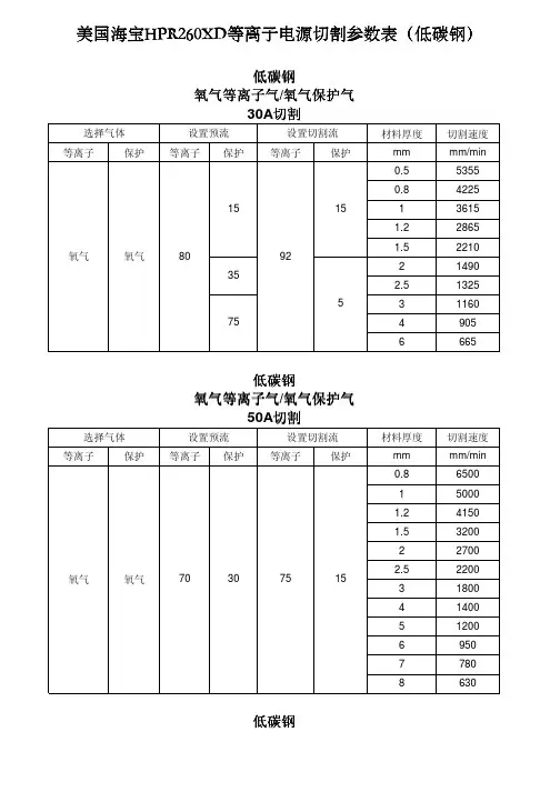
海宝HP260讲解
- 格式:ppt
- 大小:4.44 MB
- 文档页数:43

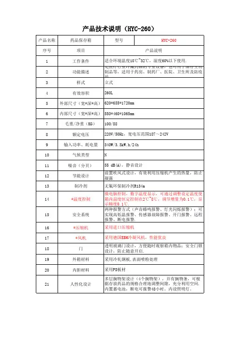
产品名称药品保存箱型号HYC-260序号项目1工作条件2功能描述3样式4有效容积5外部尺寸(宽*深*高)6内部尺寸(宽*深*高)7毛重/净重(KG)8额定电压9输入功率、耗电量10气候类型11噪音(分贝)12节能设计13制冷剂14*温度控制15安全系统16*压缩机17*风机18门19外箱材料20内胆材料21人性化设计采用德国EBM冷凝风机,性能优良透明玻璃门设计,方便随时观察箱内物品;安全门锁设计,防止随意开启.采用冷轧钢板,表面喷粉处理采用PS板材多层搁物架设计(4个搁物架),并有搁物条,可根据存放药品的规格合理地调整间隙,充分利用空间.内置蓄电池,断电可报警48小时。
内设照明灯。
采用进口压缩机丹佛斯 NL7.3MF620*655*1720mm550*460*1065mm100/88220V/50Hz,宽电压范围187~242V340W/3.3kW.h/24hN55 dB(A),静音设计前置吹风式设计,有效利用压缩机产生的热量,防止凝露无氟环保制冷剂R134a微电脑控制,数字温度显示,可通过调整设定温度使箱内温度恒定控制在2℃~8℃,调节增量为0.1℃,显示精度0.1℃.两种报警方式(声音蜂鸣报警、灯光闪烁报警);可实现高低温报警、传感器故障报警、开门报警、远程报警、断电报警.260L产品技术说明(HYC-260)产品说明适合环境温度10℃~32℃,湿度60%以下使用.是医疗行业冷藏药品的专业设备,也可用于储存生物制品等,适用于药房、制药厂、医院、卫生所及防疫站.立式。
User ManualUSM-260Intelegient Box PCCopyrightThe documentation and the software included with this product are copyrighted 2016 by Advantech Co., Ltd. All rights are reserved. Advantech Co., Ltd. reserves the right to improve the products described in this manual at any time without notice. No part of this manual may be reproduced, copied, translated, or transmitted in any form or by any means without the prior written permission of Advantech Co., Ltd. The infor-mation provided in this manual is intended to be accurate and reliable. However, Advantech Co., Ltd. assumes no responsibility for its use, nor for any infringements of the rights of third parties that may result from its use. AcknowledgementsIntel and Pentium are trademarks of Intel Corporation.Microsoft Windows is registered trademark of Microsoft Corp.All other product names or trademarks are properties of their respective owners. Product Warranty (2 years)Advantech warrants the original purchaser that all of its products will be free from defects in materials and workmanship for two years from the date of purchase.This warranty does not apply to any products that have been repaired or altered by persons other than repair personnel authorized by Advantech, or products that have been subject to misuse, abuse, accident, or improper installation. Under the terms of this warranty, Advantech assumes no liability as a consequence of such events.Because of Advantech’s high quality-control standards and rigorous testing, most customers never need to use our repair service. If an Advantech product is defective, it will be repaired or replaced free of charge during the warranty period. For out-of-warranty repairs, customers will be billed the cost of replacement materials, service time, and freight. Please consult your dealer for more details.If you suspect your product is defective, follow the steps outlined below.1.Collect all the information about the problem encountered. (For example, CPUspeed, Advantech products used, other hardware and software used, etc.) Noteanything abnormal and list any onscreen messages that are displayed when theproblem occurs.2.Call your dealer and describe the problem. Please have your manual, product,and any relevant information to hand.3.If your product is diagnosed as defective, obtain a return merchandize authori-zation (RMA) number from your dealer. This allows us to process your returnmore quickly.4.Carefully pack the defective product, a completed Repair and ReplacementOrder Card, and a proof of purchase date (such as a photocopy of your salesreceipt) into a shippable container. Products returned without a proof of pur-chase date are not eligible for warranty service.5.Write the RMA number clearly on the outside and ship the package prepaid toyour dealer.Part No. 200K310F10Edition 1Printed in China May 2016Warnings, Cautions, and NotesDocument FeedbackTo assist us in improving this manual, we welcome any comments and constructive****************************************************************Technical Support and Assistance1.Visit the Advantech website at to obtain the latestproduct information.2.Contact your distributor, sales representative, or Advantech's customer servicecenter for technical support if you need additional assistance. Please have thefollowing information ready before calling:–Product name and serial number–Description of your peripheral attachments–Description of your software (operating system, version, application software,etc.)–Comprehensive description of the problem–The exact wording of any error messagesPacking ListBefore setting up the system, check that the items listed below are included in theshipment and in good condition.USM-260–Warranty card–Adaptor–User manualIf any of these items are missing or damaged, please contact your distributor or salesrepresentative immediately.Warning!Warnings indicate conditions that if not observed, can cause personalinjury!Caution!Cautions are included to help prevent hardware damage or data losses.For example,“New batteries are at risk of exploding if incorrectly installed. Do notattempt to recharge, force open, or heat the battery. Replace the batteryonly with the same or equivalent type recommended by the manufac-turer. Discard used batteries according to the manufacturer's instruc-tions.”Note!Notes provide additional optional information.Safety Instructions1.Read these safety instructions carefully.2.Retain this user manual for future reference.3.Disconnect this equipment from all AC outlets before cleaning. Use only a damp cloth to clean. Do not use liquid or spray detergents.4.For pluggable equipment, the power outlet socket must be located near the equipment and easily accessible.5.Protect this equipment from humidity.6.Place this equipment on a reliable surface during installation. Dropping or letting the device fall may cause damage.7.The openings on the enclosure are for air convection. Protect the equipment from overheating. Do not cover the openings.8.Ensure the voltage is correct before connecting the equipment to a power outlet.9.Position the power cord away from high-traffic areas. Do not place anything over the power cord.10.All cautions and warnings on the equipment should be noted.11.If unused for a long time, disconnect the equipment from the power source to avoid damage from transient overvoltage.12.Never pour liquid into an opening. This may cause fire or electrical shock.13.Never open the equipment. For safety reasons, the equipment should be opened only by qualified service personnel.14.If one of the following situations occurs, have the equipment checked by servicepersonnel:⏹ The power cord or plug is damaged.⏹ Liquid has penetrated the equipment.⏹ The equipment has been exposed to moisture.⏹ The equipment is malfunctioning, or does not operate according to the usermanual.⏹ The equipment has been dropped and damaged.⏹ The equipment has obvious signs of breakage.15.Do not store this equipment in an environment where the temperature fluctuatesbelow -20 °C (-4 °F) or above 60 °C (140 °F) as this may cause damage. Theequipment should be stored in a controlled environment.16.Batteries are at risk of exploding if incorrectly installed. Replace only with thesame or equivalent type recommended by the manufacturer. Discard used bat-teries according to the manufacturer’s instructions.The sound pressure level at the operator position does not exceed 70 dB (A) inaccordance with IEC 704-1:1982.DISCLAIMER: These instructions are provided according to IEC 704-1. Advantechdisclaims all responsibility for the accuracy of any statements contained herein.17. If protective is used as a safeguard, the instructions shall require connection of the equipment protective earthing conductor to the installation protective earthing conductor(for example,by means of a power cord connected to a socket-outlet with earthing connection).Safety Precaution - Static ElectricityFollow these simple precautions to protect yourself from harm and the products from damage.⏹To avoid electrical shock, always disconnect the power from your PC chassisbefore you work on it. Don't touch any components on the CPU card or othercards while the PC is on.⏹Disconnect power before making any configuration changes. The sudden rushof power as you connect a jumper or install a card may damage sensitive elec-tronic components.ContentsChapter1General Information (1)1.1Introduction (2)1.2Specifications (2)1.2.1General Specifications (2)1.2.2Environmental Specifications (2)1.3Dimensions (3)Chapter2System Setup (5)2.1Quick Tour of the Device (6)Figure 2.1Front view of UBX-310F (6)Figure 2.2Rear view of UBX-310F (6)2.2Installation Procedures (6)2.2.1Connecting the Power Cord (6)2.2.2Connecting the Mouse and Keyboard (6)2.2.3Activating the Power Source (6)2.3Running the BIOS Setup Program (7)2.4Installing System Software (7)Chapter11.1Introduction1.2Specifications1.2.1General Specifications⏹Dimensions (W x H x D):⏹Weight:2.3 kg ⏹Power supply: +19 VDC @ 90 W (Maximum)⏹Storage: Supports 2 x internal Mini SATA slot ⏹RAM: ⏹Serial ports:2 x COM ports ⏹USB: Supports up to 8 x USB interfaces,4xUSB3.0,4xUSB2.0 optional ⏹Battery: 3 V @ 195 mA lithium battery1.2.2Environmental Specifications⏹Operating Temperature: 0 ~ 40 °C (32 ~ 104 °F)⏹Storage Temperature: -20 ~ 60 °C ⏹Relative humidity: 10 ~ 95% @ 40 °C (non-condensing)⏹Shock: 10 G peak acceleration (11 ms duration)⏹Vibration: 5 ~ 500 Hz 0.5 Grms, random ⏹Certification: CCC/FCC/CE/BSMI/UL/CBDDR4-2133 MHz SO-DIMM memory Up to 32GB USM-260 is an intelligent multi-functional box PC equipped with the 6th generation Intel desktop processor. The system’s compact design and multiple IO interface support to integrate in diverse peripherals and various application solutions that targeted at a wide range of applications (eg. Self-service system, POS system, Digital Signage Player, Edge Computing, AI and so on)in semi-industrial, retail and hospital markets.240 x 57 x 210mm 2xSATA3.0CPU :I nt el ® Celeron G3900TE/Pentium G4400TE/i3-6100TE/i5-6500TE/i7-6700TE ⏹(Optional up to 4xCOM)Chapter 1General Information1.3DimensionsChapter22.1Quick Tour of the DeviceBefore setting up the device, take a moment to familiarize yourself with the functions of the controls, drivers, connectors, and ports located on the front panel, as illustrated in Figure 2.1.Figure 2.1 Front viewTurn the computer to view the I/O, as shown in Figure 2.2.(The I/O interfaces include serial ports, USB slots, audio-in jack, etc.)Figure 2.2 Rear view2.2Installation Procedures2.2.1Connecting the Power CordThis product only supports DC power (19 VDC, max. 90 W). Be sure to hold the plug end when plugging or unplugging the power cord.2.2.2Connecting the Mouse and KeyboardConnect the mouse and keyboard via the USB ports located in the I/O section at the rear of the computer.2.2.3Activating the Power SourceVerify that the power cord is connected to the power input port of the device. Then connect the plug end of the power cord to the wall power outlet.Chapter 2System Setup2.3Running the BIOS Setup ProgramIn most cases, the computer will have been setup and configured by the dealer or SI prior to delivery. However, some of the computer's BIOS (Basic Input-Output System)setup programs may need adjustment to set the system configuration data, such as the current date and time, or type of hard drive installed. The setup program is stored in read-only memory (ROM) and can be accessed when activating or resetting the computer, or by pressing “Delete” immediately after powering up the computer. 2.4Installing System SoftwareRecent releases of operating systems by major vendors include setup programs that load automatically and guide users through the entire installation process. The steps necessary to install an operating system on the computer hard drive are explained below.If necessary, insert the OS CD into the diskette until the release button pops up.The system BIOS supports bootup directly from the USB-CDROM drive. Users can insert the OS CD directly into the USB-CDROM drive.Power on the computer, or reset the system by pressing “Ctrl” + “Alt” + “Del” simulta-neously.Select Boot ->Boot Configuration ->Operation System Select to install the correct OS.After clicking “Save & Exit”, the computer will automatically load the operating systemfrom the diskette or USB-CDROM drive.Note!Some distributors and system integrators may have preinstalled systemsoftware before shipping the computer.When presented with the opening screen of a setup/installation program, simply fol-low the onscreen instructions. The setup program guides users through configuring and installing the hard drive and operating system.Note!notice. If in doubt, check Advantech’s website or contact our applicationThe drivers and unilities of USM-260 are subject to change withoutChapter 2 System Setup。

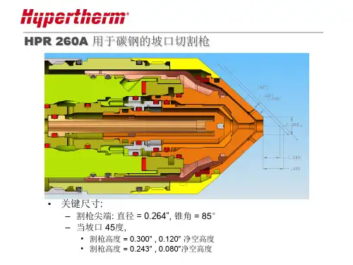
Superior cut quality on mild steel and stainless steelHyPerformance ®Plasma HPR260XD®The HPR260XD delivers superiorHyPerformance cutting across a broad range of application needs, from very thin to heavier thicknesses.Dross free* 32 mm (1-1/4")Production pierce 38 mm (1-1/2")Maximum cutting capacity64 mm (2-1/2")Production pierce 32 mm (1-1/4")Maximum cutting capacity50 mm (2")Production pierce 25 mm (1")Maximum cutting capacity50 mm (2")* Feature and material type can influence dross free performance.Superior cut quality and consistencyHyPerformance Plasma cuts fine-feature parts with superior quality and consistency, eliminating the cost of secondary operations.• H yDefinition ® technology aligns and focuses the plasma arc for more powerful precision cutting up to 64 mm (2-1⁄2") on mild steel.• N ew HDi™ technology delivers HyDefinition cut quality on thin stainless steel from 3 to 6 mm (12 ga. to 1/4").• P atented system technologies deliver more consistent cut quality over a longer period of time than other systems available on the market.Maximized productivityHyPerformance Plasma combines fast cutting speeds, rapid process cycling, quick changeovers and high reliability to maximize productivity.Minimized operating costHyPerformance Plasma lowers operating cost and improves profitability.• L ongLife ® technology significantly increases consumable life and enables consistent HyDefinition cut quality over the longest period of time.Unmatched reliabilityExtensive testing, backed by more than four decades of experience, guarantees the Hypertherm quality you can count on.2** H35 = 35% H, 65% ArsCut with confidence• Hypertherm is ISO 9001: 2000 registered.• Hypertherm’s full-system warranty provides complete coverage for one year on the torch and leads and two years on all other system components.• Hypertherm’s plasma power supplies are engineered to deliver industry leading energy efficiency and productivity with power efficiency ratings of 90% or greater and power factors up to 0.98. Extreme energy efficiency, long consumable life, and lean manufacturing lead to the use of fewer natural resources and a reduced environmental impact.Hypertherm, HyPerformance, HPR, HyDefinition, HDi and LongLife are trademarks of Hypertherm Inc. and may be registered in the United States and/or other countries. All other trademarks are the properties of their respective owners.© 8/2016 Hypertherm Inc. Revision 6 870800One of Hypertherm’s long-standing core values is a focus on minimizing our impact on the environment. Doing so is critical to our, and our customers’, success. We are always striving to become better environmental stewards; it is a process we care deeply about.* H35 and N 2 mixed plasma gas requires the use of an autogas console. T he operating data chart does not list all processes available for the HPR260XD. Please contact Hypertherm for more information.。

Samsung POWERbot ™ R7260 Pet Plus Robot Vacuum VR2AR7260WC Powerful Robot VacuumFeatures• Self-Clean Soft Action Brush • 40x More Powerful Suction 1• V isionary Mapping ™ Plus and FullView Sensor ™ 2.0• Wi-Fi Connectivity • Edge Clean Master • DC Motor •C ycloneForce ™ Technology • EasyPass ™ Wheels • Intelligent Power Control • Coverage Map Report • Multiday Schedule • Point Cleaning ™• Multi-Surface Cleaning • C leaning Time: Up to 90 Minutes • 1-Year Warranty • 10 15/16" Cleaning Path Signature FeaturesSelf-Clean Soft Action Brush• A utomatically detangles and removes pet hair that collects around the brush while picking up fine dust and improved crevice cleaning.40x More Suction Power• D elivers 40x more powerful cleaning on all floor types when compared to a conventional robot vacuum with a circular design.11 Tested internally on Samsung POWERbot VR7000 and Samsung conventional VR10F71UCAC.Visionary Mapping ™ Plus and FullView Sensor ™ 2.0• O nboard camera and improved sensors create the ideal cleaning path for extensive multi-room cleaning while cutting down on cleaning time. Coverage map shows you where POWERbot has cleaned.Visionary Mapping ™ Plus and FullView Sensor ™ 2.0Self-Clean Soft Action Brush Available ColorPure Silver• 32 cm/sec Cleaning Speed • 160-Minute Recharging Time • 78 dBA • 20W Suction Power (SPOT)• 8W Suction Power (Turbo)• 4W Suction Power (Normal)• 2.5W Suction Power (Quiet)• 0.3-Liter Dustbin Capacity • Auto Docking • Recharge and Resume • Voice Guide • Remote • Touch Button Control • C leaning Modes: Auto, Repeat, Manual, Spot • S uction Control Modes: Turbo, Normal, Quiet Accessories • M agnetic Tape • E xtra Filter • C ombo BrushActual color may vary. Design, specifications, and color availability are subject to change without notice. Non-metric weights and measurements are approximate.©2019 Samsung Electronics America, Inc. 85 Challenger Road, Ridgefi eld Park, NJ 07660. Tel: 800-SAMSUNG. . Samsung is a registered trademark of Samsung Electronics Co., Ltd.Samsung POWERbot ™ R7260 Pet Plus Robot Vacuum VR2AR7260WCPowerful Robot VacuumWarranty 1-Year Warranty Product Dimensions & Weight (WxHxD)Dimensions: 137/16" X 313/16" X 133/4"Weight: 9.5 lbs Shipping Dimensions & Weight (WxHxD)Dimensions: 1815/16" X 195/8" X 67/16"Weight: 15.7 lbs Color Model Code UPC Code Pure Silver VR2AR7260WC/AA 8872763207791 Tested internally on Samsung POWERbot VR7000 and Samsung conventional VR10F71UCAC.2Through SmartThings Application.3Amazon Alexa devices, Bixby devices and the Google Assistant devices sold separately.4Than our previous models.FeaturesSelf-Clean Soft Action Brush – Automatically detangles and removes pet hair that collects around the brush while picking up fi ne dust and improved crevice cleaning.40x More Powerful Suction – Delivers 40x more powerful cleaning on all fl oor types when compared with a conventional robot vacuum with a circular design.1Visionary Mapping ™ Plus and FullView Sensor ™ 2.0 – Creates optimal cleaning path and avoids obstacles.Wi-Fi Connectivity –Allows you to remotely control your robot vacuum on your smartphone 2 or through voice-enabled devices such as Bixby, Amazon Alexa or the Google Assistant.3Edge Clean Master – Thoroughly cleans corners and edges of the wall.CycloneForce ™ Technology – Long-lasting suction power with less clogging.4EasyPass ™ Wheels – Large wheels move smoothly over obstacles.Intelligent Power Control – Automatically detects surface types to select the ideal suction power.Coverage Map Report – Remotely check cleaning history with your smartphone to see where it has vacuumed.Multiday Schedule – Program cleaning time.Point Cleaning ™ – Lets you simply point for on-demand vacuum cleaning of pet hair and dander.Multi-Surface Cleaning – Cleans all floor surfaces (carpet, hardwood, tile).Cleaning Time – Up to 90 minutes.Wide Motorized Brush – With a 1015/16" cleaning path, covers a wide area with every pass for efficient cleaning.Cleaning Speed – Moves at 12.6 inches per second (32 cm/sec).Sound Level – 78 dBA.20W Suction – Powerful and reliable DC motor.Easy-to-Clean, See-Through Dust Canister – 0.3-liter capacity.Auto Docking – Ensures the vacuum is charged (160-minute recharging time).Recharge and Resume – Automatically returns to docking stations to recharge then resumes cleaning until the job is complete.Voice Guide – POWERbot gives you spoken updates about its status, cleaning modes and any errors.Cleaning Modes – Auto, Repeat, Manual, Spot.Suction Control Modes – Three control modes (Turbo, Normal, Quiet) operated by soft-touch buttons.Li-ion Battery – Provides long battery life and consistent power.。
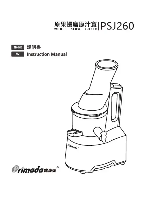
原果慢磨原汁寶W H O L E S L O WJ U I C E R PSJ26021說明書2感謝您選購寶康達產品 —— 原果慢磨原汁寶!希望您使⽤愉快,我們相信這款全新原果慢磨原汁寶幫助您烹調更快速⽅便,讓您重新感受到烹飪的樂趣及擁有不⼀樣的美食滋味。
使⽤中如果遇到任何問題,請聯絡我們的售後服務中⼼,將有專業⼈員為您解答問題。
如欲了解更多產品資訊,請瀏覽:本資料產品以實物為準,本公司保留產品更新的權利,如有變動,恕不另⾏通知。
感謝您的選擇!...................................................................................................................................Instruction ManualZH-HK1. 安全注意事項2. 產品組成 2.1包裝隨附物件 2.2技術參數目錄5. 疑難排解 (2) (3)...................................................................................................3..........................................................................................................4 (5)......................................................................................................5..........................................................................................................5....................................................................................................8.........................................................................................................10 (15) (19)組件名稱 2.3 3. 產品使用4. 清洗與保養 (4)3.1安裝前須知 3.2安裝方法 3.3使用前須知 3.4操作說明2使用電器產品前請仔細閱讀此說明書。

PHBJ-260型便携式pH计使用说明书上海精密科学仪器有限公司PHBJ-260型便携式pH计使用说明书目录1 概述 (1)2 仪器主要技术性能 (3)3 仪器结构 (5)4 仪器使用 (12)5 仪器缺省设置 (25)6 仪器的维护与维修 (25)7 仪器的成套性 (26)8 附录 (27)1 概述欢迎您选用PHBJ-260型便携式pH 计,请您在初次使用或长时间未使用本仪器前先详细阅读使用说明书,它将帮助您更好的使用本仪器。
1.1 适用范围PHBJ-260型便携式pH 计是一台智能型的分析仪器,它适用于石油、化工、医药、电厂、环保、高等院校和科研机构等单位。
既可测量水溶液中pH值,也可测量各种离子选择电极的电极电位和溶液温度。
仪器外形新颖、携带方便,适用于现场和野外操作。
仪器电池连续工作寿命长,亦可作为实验室的常规分析设备。
1.2 仪器特点●仪器采用微处理器技术,具有全自动校准和断电保护等功能。
●仪器采用低功耗设计,具有欠压显示、自动关机等电源管理功能。
●仪器可配E-301-C型三复合电极,亦可配E-201-C-9型复合pH电极和T-818-B-6型温度电极。
●可选择五种pH缓冲溶液对仪器进行一点或二点标定。
●仪器具有自动温度补偿和手动温度补偿两种方式。
●用户通过调节等电位点,可以测量纯水、超纯水和锅炉水的pH值。
●仪器对测量结果可以贮存、删除、查阅。
最多可贮存各250套pH或mV测量的实验数据。
●仪器带有RS-232接口,可接TP-16型打印机打印当前测量结果或贮存的数据;亦可接计算机通讯,传递当前测量数据或贮存数据。
1 ●仪器采用宽屏幕液晶显示,数字清晰,同时具有操作提示功能,使用简单方便。
采用新型材料PC面板,可靠性好。
●仪器机箱防护等级为IP65,防水防尘,适用于野外作业。
1.3 仪器功能仪器具有两种工作状态,测量状态和模式状态,在不同的状态下具有22 仪器主要技术性能2.1 测量范围pH:(0.00~14.00)pHmV:(-1800~1800)mV温度:(0.0~60.0)℃2.2 分辨率pH:0.01pHmV:1mV温度:0.1℃2.3 电子单元基本误差pH:±0.01pHmV:±0.1%(FS)温度:±0.3℃2.4 仪器基本误差pH: ±0.02pH±1个字温度:±0.5℃±1个字2.5 电子单元输入阻抗≥1×10¹²Ω2.6 仪器重复性误差≤0.01pH2.7自动温度补偿范围(0.0~60.0)℃3 2.8 标定方式一点或二点自动标定2.9 仪器正常工作条件环境温度:(5~35)℃环境防护等级:IP65供电电源:4节AA碱性电池除地磁场外,周围无电磁场干扰2.10 外形尺寸(mm)210×100×45 (长×宽×高)2.1 重量(kg)约0.543 仪器结构3.1 仪器组成(1)显示屏(2)键盘(3)电极图1仪器整机图仪器由电子单元和电极系统组成,既可以配用E-301-C型三复合电极,亦可配用E-201-C-9型复合电极和T-818-B-6型温度电极,方便用户的使用和维护。
03User Guide04ESC programming and Data checking05 Programmable parameters and instructions06Speed Governor Function07Warning Tones and ProtectionWiring diagram1Normal boot process2Explanation for the ESC Speed-governing1“*” in the form below indicate factory defaults.20230719Turn on the transmitter and push the throttle stick to the lowest pointThe ESC is connected to the battery, the motor will sound off with " 123", indicating that power turned on is normalA "beep" tone is sounded off to indicate the number of lithium batteries.Finally, a long "beep" toneindicates that the ESC self-check is complete and the motor can be driven at any time• Before using this product, read the instruction manual carefully. Ensure that the equipment is used appropriately to avoid damaging the ESC. The wrong usage will overheat the motor and may damage the electronics.• It is important to ensure that all wires soldered are properly secured to avoid short circuits from happening. A good soldering station is recommended to do such a job to avoid overheating the circuit board as well as to ensure connectors • Even though the product has relevant protective measures, always use it in a safe manner in accordance with the operating environment noted in the manual (e.g, voltage, current, temperature etc).• Always remember to disconnect the battery each time after using it. Failure to do so will cause the battery to be completely discharged, resulting in an unpredictable danger.1. Flight mode1.1. Fixed-wing mode: Suitable for fixed-wing aircrafts. In this mode, the throttle has to be more than 5% (including 5%) to start the motor and the throttle response is rapid.1.2. Helicopter External Governor mode: Suitable for helicopters without any governor or helicopters using external governors. The throttle has to be higher than 5% (including 5%) before starting the motor. After the slow start is completed, the motor will start off with a smoother manner, followed by a faster throttle response accelerated to the current throttle value;1.3. Helicopter Express Governor mode: Suitable for helicopters flying at a fixed headspeed. The throttle has to be higher than 40% (including 40%) before starting the motor. In the soft start process, the motor starts in an ultra-smooth acceleration to complete the speed calibration.1.4. Helicopter Store Governor mode: Suitable for helicopters flying at a fixed headspeed. The throttle in this mode has to be more than 40% (including 40%) before starting the motor. The motor starts in an ultra-smooth manner. After the soft start, the governor will be activated.*Note that speed calibration must be done each time when other modes are switched to this mode.2. LiPo cellsThe number of battery cells can be detected automatically, or set manually. Select Auto-calculation to calculate the number of battery cells automatically. Errors on battery cells will be detectable during self-test and can be adjusted accordingly.3. Low-Voltage Cutoff TypeSoft Cutoff: The output power will be gradually reduced to 50% of the total power output after low voltage protection is triggered. Hard Cutoff: Disconnect the power output immediately after low voltage protection is triggered.4. Cutoff Voltage2.8V-3.8V per cell with 0.1V step adjustability. For example, When using 6S lithium batteries, the protection voltage should be set by ×6. 5. BEC VoltageThe ESC is built-in with a BEC of 5-12V and has the capability to adjust 0.1v per step.6. Response timeAdjust the response speed of the throttle in “helicopter Express Governor” or “store Governor”. The higher the value, the slower the throttle response speed. 4-25 fully adjustable.7. Governor parameter PThis parameter is for controlling the ESC to compensate the amount of the motor speed during the process of maintaining the speed-governing effect; the higher the value, the bigger the amount; and vice versa. This function functions together with the Governor Parameter I. 8. Governor parameter IWhen the speed falls below, or exceeds the value set, the speed is compensated by the ESC. This parameter is used to resize the degree of rotation. Too large parameters will cause excessive make-up, and too small parameters will cause insufficient replacement.9. Auto Restart TimeThis feature is only available in helicopter Express or Store Governor modes. It is the time set to push the throttle from more than 40% to 25% to 40% throttle range, and then push back more than 40%. The parameter will not takeeffect when the throttle range is below 25% or between 25%-40% beyond the set time. The ESC will execute the "helicopter Express / storage fixed speed" modes of the default start-up process only if the throttle range is above 40%. 10. Restart acceleration time1-3 seconds, with 0.5 seconds step adjustability . This parameter controls the time required for the motor to accelerate from zero to full speed during a quick restart. (This is an auxiliary function and is only valid if the “time to turn off and land” function is valid)11. Brake typesNormal brake: This function will stop the motor from braking during operating according to the value set on the braking force.12. Brake ForceThe greater the value, the shorter the time taken for the motor to come to a standstill. 0-100%, with 1% step adjustability. This function is only valid in normal brake mode.13. TimingThis item is for adjusting the ESC timing. It’s adjustable between 0 and 30° with the step of 1°. 14. Motor directionThis item is for setting the rotation direction of the motor, and it’s “CW” by default. After connecting the motor to the ESC, (if the motor rotates clockwise); when setting this item to “CCW”, the motor will rotate counterclockwise; (if the motor rotates counterclockwise), when setting this item to “CCW”, the motor will rotate clockwise. 15. Active FreewheelingThis item can be enabled or disabled when the “Flight Mode” is set to the “Fixed-wing” or “Helicopter (External Governor) mode; it’s fixed at “Enabled” when the “Flight Mode” is set to the “Helicopter (Elf Governor)” or“Helicopter (Store Governor)” mode. With this item enabled, the throttle linearity will be great. 16. Start-up forceThis item is for adjusting the start-up force of the motor (during the start-up process). The higher the value, the larger the start-up force. It’s adjustable between 1 and 7.Establish the “Motor RPM-Throttle Amount Curve” via the speed standardization, and then set the throttle amount to some fixed value on the transmitter, in that condition, the motor will output the RPM corresponds to the throttle amount and keep rotating at that speed.• In the “Helicopter (Express Governor)” mode, the ESC won’t save the “Motor RPM-Throttle” curve after it’s disconnected from the battery, so every time when the ESC is connected to the battery, it will standardize the speed, otherwise you cannot use the speed-governing function normally. In this mode, due to the differences like batteries’ discharge capacities, the standardized RPM is a little different every time. In consequence, at the same throttle amount, the RPM may be a bit different when using different batteries, but this won’t affect the speed-governing effect.• In the “Helicopter (Store Governor)” mode, the ESC will save the “Motor RPM-Throttle” curve after the speed standardization. So after adjusting to this mode from any other mode, you need to standardize the speed when the ESC is connected to the battery for the first time and you needn’t standardize the speed again after disconnecting the ESC from the battery first and then connecting it to the battery again. If adjusting to any other mode from this mode and saving the “Motor RPM-Throttle” curve, and then adjusting back to this mode, the “Motor RPM-Throttle” curve saved by the ESC will be cleared, and you need to standardize the speed once again. If your ESC remains in this mode in future, then it will always carry out its operation as per the saved “Motor RPM-Throttle” curve. When standardizing the speed for the first time, we recommend using a battery in good condition. After the RPM standardization, change another battery with the same number of cells to fly your aircraft. At the same throttle amount, the RPM should be consistent with the RPM of the first flight.1) The principle of RPM StandardizationDuring the RPM standardization, the ESC will establish a “Motor RPM-Throttle” curve by itself based on the actual battery voltage and the actual KV rating of the motor. Therefore , you need to standardize the speed with a fully charged battery, and ensure the main blade pitch is 0° (in order to make the helicopter not take off). In general, people use the default “Throttle Curve & Pitch Curve” of the transmitter (as shown below) when they standardize the speed.Attention! Please ensure the main blade pitch is 0° and the throttle amount is above 40% (we recommend using 50%) when standardizing the speed.2) Procedures of RPM Standardization• We recommend using the default “Throttle Curve & Pitch Curve”. ( If you don’t want to use the default setting, then please ensure the throttle amount is 50% and the main blade pitch is 0° when the motor rotates.• Turn on the transmitter, move the throttle stick to the bottom position and then wait for the ESC completing the self detection.• If you’ve set the “throttle cut” function, please lock the “throttle cut”, and then move the throttle stick to the 50% position and then unlock the “throttle cut”. If there is no “throttle cut”, then you can move the throttle stick to the 50% position directly.• The ESC drives the motor to rotate, the main blades start to accelerate slowly (because the main blade pitch is 0°, so the helicopter won’t take off, but you still needs to be careful), you need to wait for the acceleration completing and the speed getting stable, and then lock the “throttle cut” or move the throttle stick to the bottom position.• The ESC will stop driving the motor, the main blades start to slow down and then stop rotating. • The RPM standardization completes.Attention! Please calibrate the throttle range before the RPM standardization. There will be no need if you’ve carried out the ESC/Radio Calibration when the first time you used this the ESC or you didn’t restore the settings to factory defaults after the calibration (changing the transmitter & receiver is an exception).Formula: Main Blades’ RPM (at the 100% throttle)=Max. RPM÷ (Motor Poles ÷2)÷Drive Gear RatioThe Main Blades’ RPM (at the 100% throttle) in the example is: 157*1000÷(10÷2)÷(120÷13)≈3400 RPM If the Main Blades’ RPM needs to remain at 2700RPM during the 3D flight process, then you need to set the throttle amount (set in the Helicopter “Store Governor” mode) to 2700÷3400≈ 0.8, that is you need to set the throttle amount to 80%. At this time, you need to set the value of the 3D throttle curve (i.e. IDLE1) to 80% (as shown below):So next time, when you fly your helicopter, let it take off in the “Normal” mode first and then switch to the “IDLE1” mode directly, then your helicopter can start the 3D flight with 80% throttle amount (that’s the standardized speed of 2700 RPM).Notes: in general, you can set and save 2/3 sets of throttle curve IDLE settings on a high quality transmitter (and you need to adjust the main blade pitch of each set of IDLE setting as per the actual demand), and switch betweenthese settings during the flight and have the different throttle amount (set in the Helicopter “Store Governor” mode) to meet the different RPM demands (i.e. when setting IDLE1 to 70%, IDLE2 to 80%, IDLE3 to 90% in the way as explained earlier, then you will have three different throttle amounts (set in the Helicopter “Store Governor” mode) to meet different flight demands.2. In the “Helicopter (Express Governor)” mode, you are not allowed to check the Max. RPM, so you need to set the transmitter in advance and check the main blades’ RPM with the help of some external device (like RPM viewer) and then decide the throttle amount that you need to set. Here you can calculate the throttle amount roughly. For example, if the KV rating of the motor is 480KV, the battery is a 12S LiPo, the motor drive gear is 13T and the main drive gear is 110T, then the main blades’ RPM is: KV Rating × Battery Voltage ÷Drive Gear Ratio (480*12*4.2*13÷110≈2850). So if you want your motor to rotate at the speed of 2150RPM, then the throttle mount is: 2150÷2850≈0.75 (that is 75%), and then you adjust it accordingly as per your preference or the data you read on the RPM viewer.• In “Helicopter (Store Governor)” mode, connect the ESC to the LCD program box or WIFI Express module when the RPM standardization completes, and then find the record (as shown below) as per the instruction about the “ data checking” process.The value shown in the image is just an example, pleas take the value actually displayed on your LCD program box as standard. This value is the max. electrical RPM and the motor can reach at the 100% throttle.• Take a helicopter with single reduction gear unit as an example, the motor poles is 10, the motor drive gear is 13T and the main drive gear is 120T (that the drive gear ratio is 9.3), and then you can get the main blades’ RPM at the 100% throttle.1. In “Helicopter (Store Governor)” mode, you can check the standardized speed (Max. RPM) and needn’t standardize the speed every time when the ESC is connected to the battery as in the “Helicopter (Express Governor)” mode, so it’s more convenient. We recommend using this mode in the condition that you’re using fixed motor, drive gear ratio and battery (with same cell count). In this mode, only if the drive gear ratio is accurate, the main blades’ RPM corresponds to the throttle amount (set in the Helicopter “Store Governor” mode) that you will get will be accurate as well. About how to “set the speed-governing function” in this mode, let’s take an example .1.2. Protection function description• Abnormal power-on voltage protectionThe ESC enters a protective state once the input voltage detected is not in the operating range. Prompting LED light to flash. • Start-up protectionThe start-up protection will be able to detect the motor speed from when the speed stops rising or the rising speed is unstable. If the throttle input is less than 15%, the ESC will try to restart automatically; (This may occur due to; Poor contact between the ESC and motor connections, individual output wires, faulty motor, propellers blocked by other objects, Binding gears, etc.) • Temperature protectionWhen the operating temperature of the ESC has exceeded 110 degrees Celsius, power will be gradually reduced for safety, but will not be turned off. There will still be up to 50% of power, to ensure that the motor has the power to land. After the temperature drops, the ESC will gradually be restored back to maximum power. The ESC temperature must not exceed 70 degrees or it will not work. Prompting LED light to flash (above is the soft-off protection mode, if you choose hard-off, cut off the power directly) • Throttle signal loss protectionWhen the throttle signal is lost for more than 0.25 seconds, the output is immediately switched off to avoid further damage due to the propeller rotating at a high speed. Once the signal has been restored, the power output will be restored.• Overloading protectionWhen there is a sudden surge of current, power will be cut off and will be restarted. If the load is still abnormal after the restart, the power will be completely cut off. • Low voltage cutoff protectionWhen the operating voltage of the ESC has exceeded the protection voltage set, power will be gradually reduced for safety, but will not be turned off. There will still be up to 50% of power, to ensure that the motor has the power to land.• Over-current protectionThe current will be cut off immediately once the set value has been breached.RPM Standardization2How to Set the Governor3700-800 class electric helicopters (main rotor length 700-880mm), or fixed-wing aircraftsPLATINUM 260A HV SBEC V5Switched-Mode BEC; output voltage 5-12V adjustable (adjusted 0.1V); output current cont. 10A, Peak 30A89 x 50 x 34mm / 297g (With wires)① BEC output wire (red, brown): The additional BEC output wire is plugged into the receiver battery dedicated channel or any available channel. (For better BEC power output, it is recommended to insert the BEC cable into a battery-specific channel or any available channel)② RPM signal wire (yellow): electrical RPM output line of the motor needs to be connected to the RPM in of an external device (such as a Flybarless system gyro).③ Throttle signal wire (white, red, black): Insert into the receiver throttle channel. Depending on the receiver type, the whitewire is to transmit the throttle signal, whereas the red and black lines are parallel to the output of the internal BEC (e.g. the BEC voltage output wire and ground wire)Throttle stick calibration operation method3Use Multifunction LCD program box to program ESC parameters (need to purchase separately)1Use OTA Module to program the ESC parameters (need to purchase separately)2Turn on thetransmitter and push the throttle to the 100% TH pointESC connect battery, motor will sound " 123", indicating that power turned on is normalThen motor will sound off with a “beep-beep, indicating calibration for the highest point is successful.Next, push the throttle stick to the minimum with in 5 seconds, and wait 1 second for the throttle lowest point to be calibrated successfully..A "beep" tone is then sounded off to indicate the number of lithium batteries.Finally, a "beep" tone indicates that the system is ready to take off at any time2. Setting methods• Connect the ESC to LCD program box as shown above, and then connect the battery to the ESC.• The current firmware version will be displayed once the power is turned on.• Press "ITEM" to browse through the parameters, and press "VALUE" to change the settings;• Press OK to save the settings;• Repeat step 3) and step 4) to modify the settings of other parameters.• Once completed, disconnect the ESC from the battery and unplug the wire between theESC and LCD program box. Power up again and you are ready to run the new settings. Note: Any parameter changes will require the ESC to be re-powered to take effect.3. Check the ESC running data• Do not disconnect the ESC after the flight, then connect the ESC and LCD program box asshown above;• The version of the current firmware will be displayed once you have connected the LCD program box to the ESC.• Press "ITEM" key continuously, and after browsing the parameters of the ESC, the status data (minimum voltage, maximum temperature, maximum speed, etc.) of the ESC will appear.2. Setting methods• Connect the ESC and OTA module as shown above, then connect the battery to the ESC.• Turn on your phone's Bluetooth and connect to the OTA module 。
Micro Hi-Fi System MC260 user manualmanuel d'utilisationmanual del usarioUse of controls or adjustments or performance of procedures other than herein may result in hazardousradiation exposure or other unsafe operation.liilIndex English------------------------------------------------6Français--------------------------------------------22Español---------------------------------------------3854目錄一般事項環保資訊 (55)隨機供給配件 (55)安全須知 (55)準備工作背面的連接...........................................................56–57連接其他附屬音響器材 (57)裝入遙控器電池 (57)控制鍵本機和遙控器上的控制鍵 (58)基本功能開啟本機 (59)自動切換至省電待機模式 (59)調節音量和音效 (59)光碟機操作播放光碟 (60)選擇不同曲目 (60)在一首曲目中找尋某個段落 (60)不同的播放模式:Shuffle (亂序播放)和 Repeat (重複播放) (61)編輯曲目播放清單 (61)檢查曲目播放清單 (61)抹除曲目播放清單 (61)電台接收調諧選台 (62)編輯預設電台 (62)選擇預設電台 (63)改變調諧頻階 (63)磁帶機操作 / 錄音磁帶播放 (64)磁帶翻面 (64)翻面模式選項 (64)錄音一般說明 (64)CD 同步錄音 (65)從收音機錄音 (65)從輔助設備 (Aux) 錄音 (65)設定計時器錄音 (65)時鐘 / 計時器設定時鐘 (66)設定計時器 (66)開啟及關閉計時器 (66)開啟及關閉睡眠計時器 (66)技術規格 (67)維護保養 (67)故障排除....................................................68–69一般事項環保資訊本產品無任何不需要的包裝材料。