Causes for the formation of titania nanotubes during anodization
- 格式:pdf
- 大小:755.89 KB
- 文档页数:5
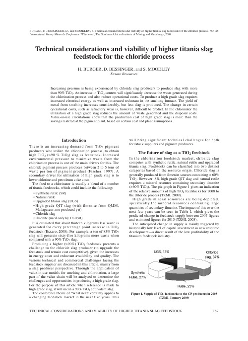
IntroductionThere is an increasing demand from TiO2pigment producers who utilize the chlorination process, to obtain high TiO2(>90 % TiO2) slag as feedstock. Increased environmental pressure to minimize waste from the chlorination process is one of the main drivers for this. The chloride pigment process produces between 2 to 5 tons of waste per ton of pigment product (Fischer, 1997). A secondary driver for utilization of high grade slag is to lower chlorine and petroleum coke costs.The feed to a chlorinator is usually a blend of a number of titania feedstocks, which could include the following: •Synthetic rutile (SR)•Natural rutile•Upgraded titania slag (UGS)•H igh grade QIT slag (with ilmenite from QMM, Madagascar, not produced yet)•Chloride slag•Ilmenite (used only by DuPont).It is estimated that about thirteen kilograms less waste is generated for every percentage point increase in TiO2 feedstock (Exxaro, 2008). For example, a ton of 85% TiO2 slag will generate sixty-five kilograms more waste when compared with a 90% TiO2slag.Producing a higher (>90%) TiO2feedstock presents a challenge to the chloride slag producer (to upgrade the feedstock and remain cost competitive), given the increases in energy costs and reductant availability and quality. The various technical and commercial challenges facing the feedstock supplier are discussed in this article, mainly from a slag producer perspective. Through the application of value-in-use models for smelting and chlorination, a large part of the value chain will be analysed to determine the challenges and opportunities in producing a high grade slag. For the purpose of this article when reference is made to high grade slag, it will mean a 90% TiO2equivalent slag. The conference theme of ‘What next’ certainly applies to a changing feedstock market in the next five years. This will bring significant technical challenges for both feedstock suppliers and pigment producers.The future of slag as a TiO2feedstockIn the chlorination feedstock market, chloride slag competes with synthetic rutile, natural rutile and upgraded titania slag. Feedstocks can be classified into two distinct categories based on the resource origin. Chloride slag is generally produced from ilmenite sources containing < 60% TiO2. However, SR, high grade QIT slag and natural rutile requires a mineral resource containing secondary ilmenite (>60% TiO2). The pie graph in Figure 1 gives an indication of the relative amounts of high TiO2feedstocks for 2008 to the chloride process (TZMI, 2009).H igh grade mineral resources are being depleted, specifically the mineral resources containing large quantities of secondary ilmenite. The impact of this over the next few years can be seen in Table I, which gives the predicted change in feedstock supply between 2007 figures and estimated figures for 2015 (TZMI, 2008).The anticipated change in supply is mainly triggered by historically low level of capital investment in new resource development—a direct result of the low profitability of the titanium feedstock industry.BURGER, H., BESSINGER, D., and MOODLEY, S. Technical considerations and viability of higher titania slag feedstock for the chloride process. The 7th International Heavy Minerals Conference ‘What next’,The Southern African Institute of Mining and Metallurgy, 2009.Technical considerations and viability of higher titania slagfeedstock for the chloride processH. BURGER, D. BESSINGER, and S. MOODLEYExxaro ResourcesIncreasing pressure is being experienced by chloride slag producers to produce slag with morethan 90% TiO2. An increase in TiO2content will significantly decrease the waste generated duringthe chlorination process and also reduce operational costs. To produce a high grade slag requiresincreased electrical energy as well as increased reductant in the smelting furnace. The yield ofmetal from smelting increases considerably, but less slag is produced. The change in certainoperational costs, such as refractory wear is, however, difficult to predict. In the chlorinator theutilization of a high grade slag reduces the amount of waste generated and the disposal costs.Value-in-use calculations show that the production cost of high grade slag is more than thesavings realized at the pigment plant, based on certain cost and plant assumptions.Figure 1. Supply of TiO2feedstocks to the CP producers in 2008(TZMI, January 2009)Experimental data on the production of high titania slag Smelting test work carried out on the 500 kW and 1.5 MW pilot furnaces at Exxaro R&D over the last decade or so has demonstrated that 92 % TiO2slags can be produced. These slag compositions have, however, only been produced for relatively short periods, as the focus previously has been on the production of 86 % TiO2slags.Figure 3 shows the relationship between the total equivalent TiO2and FeO content of titania slags (Bessinger, 2000) from data obtained from the 1.5 MW pilot furnace test work.Figure 4 shows the relationship between FeO and Ti2O3 content of slags (Bessinger, 2000). For 86% TiO2slags the Ti2O3content is in the order of 25–30%. This increases to 35–40% Ti2O3for 92% TiO2slags. Chlorinators that use slag as feedstock usually have an upper limit on the Ti2O3 content of the slag, usually 35%.Figure 5 shows the relationship between tapping temperature and the FeO content of the slags (Bessinger, 2000). Typical 86% TiO2slags can have an FeO content of approximately 11%, with tapping temperatures in the order of 1675˚C. Tapping temperatures of approximately 1725˚C is expected for 92% TiO2slags (FeO content in the order of 5%).Operational issuesThe theory does not always describe the operational issues that are experienced by the plant operators with a change in operational philosophy. An influence diagram (Figure 6) is used to describe the possible impact of changes in the furnace operations. The diagram should be read from the top where reducing conditions are a function of ilmenite feed, electricity and reductant feed. The possible operational issues that will be observed and might have a monetary impact are shown at the bottom of the diagram. The operational issues are, however, difficult to quantify, but are shown to indicate the full impact of producing high grade slag.Considerations for the chlorination of highgrade slagsThe impact of chlorinating a high grade slag must be understood to fully address the value-in-use of the proposed feedstock. Chlorination technologies as well as operating philosophies between producers differ, which may have an impact. There are, for example, at least three different plant configurations utilized for the condensation systems to handle waste oxides as discussed by Fischer (1997). ThereFigure 3. Relationship between FeO and the total equivalent TiO2content of titania slagsFigure 4. Relationship between the FeO and Ti2O3content oftitania slags Figure 5. Tap temperatures of titania slag as a function of the FeOcontent of the slagFigure 6. Influence diagram describing the impact of increasingelectric energy and reductantI ncreased slag viscosity(if less superheat)More tapholewearare also differences between the behaviour of the different feedstocks in the chlorinator. Rutile, chloride slag and synthetic rutile differ in physical properties, mineralogy and morphology, even though the TiO2content might be similar. This section will highlight some of the differences between feedstocks with particular emphasis on how high grade slag will react.Fluidization propertiesFluidization characteristics of a feedstock are determined by its physical properties such as shape, density and particle size distribution. It is not expected that these physical properties will change significantly with an increase in TiO2content of the slag. A higher TiO2content of the slag particle will slightly increase the density, but it is not considered significant enough to quantify at this stage. It can be assumed that higher TiO2levels in slag will not affect its fluidization properties.Reaction mechanisms and rates for different feedstocks The different feedstock materials react slightly differentduring chlorination, but in general they all follow the same reaction mechanism:•All products are in the gaseous phase (no diffusion control through the product layer).•The rate of chlorination is proportional to the exposed surface of the particle and this controls the rate of reaction.The morphology of the particles has an impact on the reaction rate. At the onset of chlorination, slag is denser than rutile or SR, but through the rapid chlorination of FeO in the first 10 minutes of the reaction, the slag becomes more porous. This particle then has a greater surface area on which the chlorination reaction can occur. This is in contrast to rutile where the particle shrinks as the reaction takes place only on the outside surface. This effect of FeO in slag can be seen in Figure 7 where slag (83% TiO2) chlorinates faster than rutile (Den Hoed and Nell, 2003). Increasing the TiO2content of slag will decrease the extent of FeO chlorination thereby decreasing the area available for subsequent TiO2chlorination. The rate of chlorination of high grade slag should approach that of rutile. This however needs to be confirmed.Impact of higher Ti2O3Slag has significant amounts of Ti2O3(20–30%) due to the reducing condition it has been subjected to (Reaction C). As mentioned the upper limit is usually specified as 35% Ti2O3for the chlorination process and the motivation behind this is due to management of the energy balance in the chlorinators. During the chlorination process Ti3+is oxidized to Ti4+, which is a highly exothermic reaction. In extreme cases, high levels of Ti2O3could lead to sintering of the bed material. From Figure 4, it seems that the 35% Ti2O3limit is reached at slags of > 91–92% TiO2.Impact on waste generationDecreasing the waste generated during chlorination is one of the main reasons in the quest for high grade slag. For feedstocks with TiO2contents of 10–15%, a cyclone separator (after chlorination) is used to remove condensed low vapour pressure metal chlorides and entrained coke and ore before condensation (Fischer, 1997). Waste treatment is mostly dependant on the FeO content of the feedstocks. The amount of entrainment of the feedstocks however differs and slag is more likely to be entrained due to its relative finer fraction.Methodology for value-in-use modelling of the production of high grade slagsIn order to determine the impact of changes on the furnace and how the resulting slag will affect the chlorinators, value-in-use (ViU) models were developed for each of the two processes. In the model a comparative product value (CPV) is determined for an alternative feedstock, which can be compared with a reference or base feedstock.This concept has been successfully used by Exxaro Resources since the mid 1990s (then as Iscor) specifically for the use of iron ore in the blast furnace. Value-in-use models combine technical know-how as well as financial information to provide a decision-making tool for product development and customer interaction. The ViU models were applied in this study to evaluate the production of high grade slag.Smelter value in use modelThe Smelter ViU model was used to calculate the required furnace operating parameters for the production of 85% and 90% TiO2slags. The model uses thermodynamic data for Figure 7. Rates of carbochlorination. Oxides mixed with coke (27% of the charge) reacted in a gas stream of Cl2+CO+N2at1000°C. (Den Hoed and Nell, 2003)Figure 8. Schematic presentation of the value-in-use concept(Theron, 2001)Duration of chlorination (minutes)Degreeofchlorination(%)Figure 9. Breakdown of smelting costs and income to producehigh grade slags1This cost element was included under operational costs in Figure 9•Electrode consumption1—due to the higher energy input, the electrode consumption increases.•Refractory wear 1—the impact of the higher slag temperature on refractory wear is unknown and the figure might be over- or understated. A 10% reduction in campaign life was assumed, mainly attributed to decreased tap hole life.•Pig iron revenue —The cost element is very sensitive to changes in the pig iron price assumptions. The pig iron quality and subsequent price is determined by the impurities (such as Mn, Cr, V, P) in the metal. With the increased reducing condition in the furnace, more metal is produced (7.2%), but also more impurities are transferred to the metal, decreasing the price.Although value-in-use modelling provides a quantitative tool to access the changes in products, the risk associated with production remains high. The risk of operating at elevated temperatures for extended periods of time cannot be quantified. It has been attempted through the refractory cost element quantification, but it needs to be verified. Chlorination of slagFigure 10 shows the cost elements that will change on a generic chlorination plant for a high grade slag. The impact is significant on the waste treatment cost. As mentioned earlier, this cost element is highly site specific and the cost assumptions made probably implies the worst case scenario.The comparative product value for high grade slag in a chlorinator is 10.1% per ton higher compared with the 85%TiO 2slag.The changes in operating parameters changed due to the following:•Coke consumption —higher TiO 2in feedstock requires more energy.•Chlorine consumption —more chlorine is recycled and not lost in the waste to FeCl 3, decreasing the need for make-up chlorine.•Lime usag e —less FeCl 3in the waste requires less neutralization.Not taken into account in the calculations was the increase in pigment production from the increase in TiO 2units per ton feedstock. This could make a significant contribution and could increase the slag price by as much as 18%, compared with the 85% TiO 2slag. This should,however, only be included in the calculation if the capacity constraint on the pigment plant is the chlorinator. It seems that the capacity constraint is in most cases downstream, i.e.the oxidizing plant or grinding and finishing.DiscussionThe CPV in percentage for smelting is 13.5% and for chlorination it is 10.1%, which means that the additional cost of producing high grade slag is more than the savings on the chlorinator. It does not make economic sense to produce high grade slag with the current assumptions. It should, however, be noted that these costs assumptions are very sensitive to changes in the slag and pig iron prices, as well as the waste treatment costs on the chlorination side.The pig iron prices are relatively volatile, following the steel market trends. The waste treatment and disposal costs assumed were very high, which means that for most pigment producers the CPV would actually be lower. In this respect geographical location of the pigment plant has a large effect on the chlorination CPV as waste disposal costs differ from region to region, with Europe having the highest average disposal cost.Upgrading through smelting is not the only technical option. There are other processing routes to decrease the cost of producing high grade slags:•Combination of smelting ilmenite and then leaching the impurities from the resulting slag (similar to the UGS process route)•Pre-reduction of the ilmenite, followed by smelting which would reduce the electrical energy and reductant required•Pre-heating of the ilmenite followed by smelting which would reduce the electrical energy and reductant required, but not to the same extent as pre-reduction •Partial chlorination of the ilmenite of slag to remove only the FeO•Utilizing a higher TiO 2ilmenite (>60%) as a feed to the smelting furnace which is the approach QIT is following.All these technical options address the need that a significant amount of energy needs to be introduced and also that the FeO needs to be either reduced (smelting or direct reduction) or chemically removed (leaching or chlorination). The capital outlay for these processes to basically upgrade the slag remains in disproportion to the benefit received for the incremental increase in TiO 2units.The direct smelting of ilmenite to produce a high grade slag as discussed in this article seems to be the most viable option, although not economical given current price and cost assumptions. It remains something that should be investigated and addressed in the medium term.ConclusionsAlthough the calculations show that the smelting of a 90%slag is not viable, based on the assumptions used, there are specific cases where it will be viable. It also shows that a decision on high grade slag production is very sensitive to changes in prices of specific elements. The value-in-use principles are best applied for a specific plant and conditions.Figure 10. Breakdown of cost elements for the chlorination of ahigh grade slagThe value-in-use principles are a good tool for quantifying and evaluating changes to products in complex processes. It is especially valuable in understanding customer requirements. The process technology that is being modelled, must, however, be well understood.It is clear that slag as a feedstock will play a bigger role in the industry. Synthetic rutile as a high TiO2feedstock will become less available and slag will have to fill some of the void, which will increase the pressure to produce high grade slags. Pigment producers might be prepared to pay higher prices for slag based on savings on the waste material, but it is not enough to compensate the feedstock producers. Ilmenite smelters will, however, have to do development work to address the high cost elements to produce high grade slags.ReferencesBESSINGER, D. Cooling characteristics of high titania slags, MSc thesis, University of Pretoria, 2000.DEN HOED, P. and NELL, J. The behaviour of individual species in the carbochlorination of titaniferous oxides.Heavy Minerals 2003. Johannesburg, South AfricanInstitute of Mining and Metallurgy, pp. 43–56. EXXARO, Chlorinator Value-in-Use Model (2008). FISHER, J.R. Developments in the TiO2pigments industry which will drive demand for TiO2mineral feedstocks.Heavy Minerals 1997. Johannesburg, South AfricanInstitute of Mining and Metallurgy, 1997.pp. 207–218.GELDENH UIS, J.M.A. and PISTORIUS, P.C. The use of commercial oxygen probes during the production ofhigh titania slags, Journal of the South AfricanInstitute of Mining and Metallurg y, vol. 99, no. 1,1999, pp. 41–47.PISTORIUS, P.C.Limits on energy and reductant inputs in the control of ilmenite smelters, Heavy Minerals1999, Johannesburg, South African Institute ofMining and Metallurgy, 1999. pp. 183–88.THERON, J.A.Value-in-use modeling of the conventional oxygen steelmaking process route. Internalpresentation, Iscor, 2001.TZ MINERALS INTERNATIONAL PTY LTD, Global TiO2Pigment Producers—Comparative Cost &Profitability Study, 2007.TZ MINERALS INTERNATIONAL PTY LTD, Titanium Feedstock Market Dynamics—Outlook to 2015. 2008.TZ MINERALS INTERNATIONAL PTY LTD, Mineral Sands Report, Issue 159, January 2009.TZ Minerals International Pty Ltd, Mineral Sands Report, Issue 159, March 2009.ZH OU, L., SOH N, H.Y., WH ITING, G.K., and LEARY, K.J. Microstructural changes in several titaniferousmaterials during chlorination reaction, IndustrialEng ineering Chemical Research, vol. 35, 1996.pp. 954–962.。

硫氨钛联产法生产钛白粉工艺流程Titanium dioxide is a widely used white pigment in various industries. It is commonly produced through the sulfate process, which involves the co-production of sulfuric acid and titanium dioxide. This processis known as the sulfate-ammonium titania route or the sulfur-ammonium titania process.硫酸-氨钛法是一种常用的生产钛白粉的工艺流程,该方法可以同时生产硫酸和钛白粉。
这个过程也被称为硫酸铵钛法或硫铵钛法。
In this process, titanium-containing raw materials such as ilmenite or rutile are reacted with sulfuric acid to form a solution of titanium sulfate. Ammonium hydroxide is then added to the solution to precipitate titanium dioxide, which is filtered and washed to obtain the final product. The co-production of sulfuric acid is essential inthis process, as it not only helps in the formation of titanium sulfate but also ensures the sustainability of the production.在这个工艺流程中,含钛原料如钛铁矿或金红石被硫酸反应形成钛硫酸溶液。

氧原子在α钛晶体中扩散的第一性原理研究杨亮;王才壮;林仕伟;曹阳【摘要】在材料领域杂质原子的迁移是一个基础而永恒的主题.采用基于密度泛函理论的第一性原理方法,研究了氧原子在α钛(α-Ti)晶体中的间隙占位情况,并计算了氧原子稳定占位点间隙能、电子态密度、电荷差分密度及其邻近钛原子的位移情况.采用基于过渡态搜索理论的CI-NEB (climbing image nudged elastic band)方法预测了稳定态氧原子在α-Ti晶体中的扩散路径、扩散势垒及相应的跳转频率,并由此推算出氧原子在不同位点之间跳转的扩散系数.研究结果表明,间隙氧原子在六角密排钛晶体结构中共有七种占位,但仅存在三个可稳定占据的间隙位点:八面体中心位点、六面体中心位点及0.28 nm钛一钛键中心位点.各稳定间隙位点之间的扩散具有不对称性,因此可确定三种稳定间隙氧原子位点间存在七条独立扩散路径.获取计算不同路径扩散系数所需要的微观参数,包括扩散势垒、扩散长度、不同扩散路径上鞍点氧原子的跳转频率,最终预测了不同间隙位点之间氧原子的扩散系数值,其中八面体中心扩散到邻近键位的扩散系数与实验值相符合.通过对间隙氧原子扩散行为的深入了解,希望能对控制钛合金中氧的扩散、提高钛金属中氧的含量及相关研究提供基础理论支持.%How impurity atoms move through a crystal is a fundamental and renewed issue in condensed matter physics and materials science.Diffusion of oxygen (O) in titanium (Ti) affects the formation of titanium-oxides and the design of Tibasedalloys.Moreover,the kinetics of initial growth of titania-nanotubes via anodization of a titanium metal substrate also involves the diffusion of oxygen.Therefore,the understanding of the migration mechanism of oxygen atoms in α-Ti is extremely important for controlling oxygendiffusion in Ti alloys.In this work,we show how the diffusion coefficient can be predicted directly from first-principles studies without any empirical fitting parameters.By performing the first-principles calculations based on the density functional theory (DFT) through using the Vienna ab initio Simulation Package (VASP),we obtain three locally stable interstitial oxygen sites in the hexagonal closed-packed (hcp) lattice of titanium.These sites are octahedral center (OC) site,hexahedral center (HE) site,and Ti Ti bond center crowdion (CR) site with interstitial energies of-2.83,-1.61,and-1.48 eV,respectively.From the interstitial energies it follows that oxygen atom prefers to occupy the octahedral site.From electronic structure analysis,it is found that the Ti O bonds possess some covalent characteristics and are strong and ing the three stable O sites from our calculations,we propose seven migration pathways for oxygen diffusion in hcp Ti and quantitatively determine the transition state and diffusion barrier with the saddle point along the minimum energy diffusion path by the climbing image nudged elastic band (CI-NEB) method.The microscopic diffusion barriers (△E) from the first-principles calculations are important for quantitatively describing the temperature dependentdiffusioncoefficientsDfromArrheniusformulaD=L2v*exp(-△EkBT),where v* is the jumping frequency and L is the atomic displacement of each jump.The jumping frequency v* is determined from3NΠviv*=i=1/3N-1,Πvjj=1where vi and vj are the vibration frequency of oxygen atom at the initial state and the transition state respectively.This analysis leads to the formula for calculating the temperature dependentdiffusion coefficient by using the microscopic parameters (vi and △E) from first-principles calculations 3NΠviD=L2 i=1/3N-1×exp(-△E/kBT)Πvjj=1 without any fitting ing the above formula and the vibration frequencies and diffusion barriers from first-principles calculations,we calculate the diffusion coefficients among different interstitial sites.It is found that the diffusion coefficient from the octahedral center site to the available site nearby is in good agreement with the experimental result,i.e.,the diffusion rate D is 1.0465 × 10⁻⁶ m2.s-1 with △E of 0.5310 eV.The jump from the crowdion site to the octahedral interstitial site prevails over all the other jumps,as a result of its low energy barrier and thus leading to markedly higher diffusivity values.The diffusion of oxygen atoms is mainly controlled by the jump occurring between OC and CR sites,resulting in high diffusion anisotropy.This finding of oxygen diffusion behavior in Ti provides a useful insight into the kinetics at initial stage of oxidation in Ti which is very relevant to many technological applications of Ti-based materials.【期刊名称】《物理学报》【年(卷),期】2017(066)011【总页数】10页(P251-260)【关键词】第一性原理;钛;扩散【作者】杨亮;王才壮;林仕伟;曹阳【作者单位】南京理工大学化工学院,南京 210094;海南大学材料与化工学院,海口570228;Division of Materials Sciences and Engineering, Ames Laboratory, Ames 50011, USA;海南大学材料与化工学院,海口 570228;海南大学材料与化工学院,海口 570228【正文语种】中文在材料领域杂质原子的迁移是一个基础而永恒的主题.采用基于密度泛函理论的第一性原理方法,研究了氧原子在α钛(α-Ti)晶体中的间隙占位情况,并计算了氧原子稳定占位点间隙能、电子态密度、电荷差分密度及其邻近钛原子的位移情况.采用基于过渡态搜索理论的CI-NEB(climbing image nudged elastic band)方法预测了稳定态氧原子在α-Ti晶体中的扩散路径、扩散势垒及相应的跳转频率,并由此推算出氧原子在不同位点之间跳转的扩散系数.研究结果表明,间隙氧原子在六角密排钛晶体结构中共有七种占位,但仅存在三个可稳定占据的间隙位点:八面体中心位点、六面体中心位点及0.28 nm钛—钛键中心位点.各稳定间隙位点之间的扩散具有不对称性,因此可确定三种稳定间隙氧原子位点间存在七条独立扩散路径.获取计算不同路径扩散系数所需要的微观参数,包括扩散势垒、扩散长度、不同扩散路径上鞍点氧原子的跳转频率,最终预测了不同间隙位点之间氧原子的扩散系数值,其中八面体中心扩散到邻近键位的扩散系数与实验值相符合.通过对间隙氧原子扩散行为的深入了解,希望能对控制钛合金中氧的扩散、提高钛金属中氧的含量及相关研究提供基础理论支持.近年来,钛及其合金已经成为十分重要的临床植入体材料[1],主要是由于其重量轻、力学性能优秀且与人骨力学性能相仿,尤其是其优良的生物相容性、植入后无金属离子溶出等优点大大拓展了钛及其合金材料的医学应用前景[2].纯钛植入体并无生物活性,但纯钛表面经过处理后形成的氧化物膜层具有一定的生物活性,因此科研人员利用各种方法对钛进行表面氧化改性以提高其生物相容性[3,4].目前常用的钛表面处理方法主要有热处理法[5]、微弧氧化法[6]、阳极氧化法[7]、激光热处理等[8],通过以上方法对钛金属表面进行氧化处理可以改善其生物相容性及抗腐蚀性.钛表面氧化处理过程也会引入微量的氧原子扩散进入钛基底原子间隙内并以间隙氧原子形式存在,已有研究证明氧原子很容易溶于钛金属并形成钛氧固溶体[9,10],更深入的研究发现[11−13]钛金属及其合金溶入间隙氧原子可改变钛合金的塑性[14]、疲劳、断裂性能、表面摩擦性能[15]及硬度等[16]力学性能,同时也会引起扭曲和滑移变形等一系列潜在问题.目前,钛表面改性研究领域十分活跃,但对钛氧固溶体形成过程、内在机理和影响因素的研究相对较少且不够深入.虽然钛氧固溶体研究可追溯到20世纪60年代,但由于当时实验手段的限制,研究者们获得的结果相对较为宽泛.随着检测手段的不断进步,尤其是同位素技术及核共振技术的成熟及应用,到20世纪80年代中期,实验结果已有所改善,但是由于间隙氧在钛金属中的扩散系数一般小于10−17m2·s−1,目前的实验手段所测实验结果误差较大,且扩散微观机理尚不清楚.随着计算科学的快速发展,计算机性能的提升、超级计算机计算能力的不断突破以及专业软件的进化成熟为理论研究材料微观结构及形成机理提供了条件.基于密度泛函理论的第一性原理为设计材料及预测材料性质提供了可靠方法,借此可深入研究间隙氧原子与钛晶体的结合能、扩散路径、扩散势垒,并预测扩散系数等.本文基于第一性原理,确定了间隙氧原子在α钛(α-Ti)晶体中的三个稳定间隙位及相应的结合能量,并利用CI-NEB(climbing image nudged elastic band)方法预测了间隙氧原子7种扩散路径及相应扩散势垒,并由此计算了鞍点氧原子的有效频率及跳转频率,最终预测了不同扩散路径及不同温度下间隙氧原子的扩散系数.这对控制钛合金中氧的扩散、提高钛金属中氧的含量及相关研究具有重要指导意义.目前已发现纯钛金属主要有α-Ti和β-Ti两种同素异型体,在温度低于1155 K时,钛金属主要以α-Ti形式存在.医用钛植入体服役环境温度接近体温,在300 K附近,因此主要研究α-Ti晶体与间隙氧的相互作用.α-Ti晶体结构为密排六方晶体(hcp)结构,所属空间群为194,P63/mmc,晶格常数a=b=0.2933 nm,c=0.4638nm,α=β=90◦,γ=120◦.钛原子占据的位置为(1/3,2/3,1/4)和(2/3,1/3,3/4).计算过程中为使间隙氧原子之间不产生相互作用,采用包涵54个钛原子的3×3×3钛超胞模型作为计算初始模型,在内嵌间隙氧原子之前,先对该超胞结构进行结构弛豫,使其达到能量最稳定状态.采用基于第一性原理密度泛函理论的VASP(Vienna ab initio Simulation Package)软件包[17,18].计算模型使用平面波基函数和周期性边界条件,离子和电子的相互作用采用投影缀加波方法计算,电子交换关联能采用广义梯度近似(GGA)处理,电子波函数以平面波函数处理,平面波截断能取350 eV,保证对所有元素均有足够精度.计算布里渊区积分时,选取5×5×5的中点抽样网格点,采用Γ点为中心的Monkhorst-Pack方法产生K点,离子和电子终止迭代标准分别设为能量差小于10−4和10−4eV.最小扩散能量路径采用CI-NEB方法[19]结合VASP方法确定,获取间隙氧原子在不同位置之间的迁移行为,并利用计算所得的能量势垒结合扩散位移和鞍点原子的跳转频率预测不同位点之间的扩散系数.4.1 结构优化为了更好地比较第一性原理计算采用GGA方法优化后晶格常数与真实晶格常数之间的差异,首先对α-Ti晶格进行结构优化处理,获得最稳定的晶格结构.由表1数据可以发现,计算得出的α-Ti晶格常数和实验值十分接近,误差值约为1%,表明计算所采用的势函数比较适合,截断能及迭代终止能量设置值相对合理,为后续计算的准确性提供了保障.4.2 确定氧原子的占位α-Ti晶体为密排六方晶体结构,按晶体学理论可知其存在七种间隙位置可供氧原子占据[20]:两种键间隙位(CR)、八面体位(OC)、四面体位(TE)、六面体位(HE)及两种面间隙位(BS)(四面体与八面体共面间隙位和八面体之间共面的面间隙位),具体占位如图1(b)所示.为计算氧原子占据不同间隙位时的能量,定义间隙能计算公式为式中EI为氧原子溶入钛晶体形成的间隙能;ETi+O,EO和ETi分别为存在间隙氧原子时总原子数为N+1的钛氧固溶体的能量、孤立氧原子的能量和N个钛原子晶体的能量.采用(1)式定义了间隙氧原子占据不同间隙位置时的间隙能大小并可由此判断其结构稳定性.由结合能计算结果可知,在图1所示的七种间隙位中,间隙氧原子仅能存在一个键间隙位(键长0.28 nm)、一个八面体中心位和一个六面体中心位共三个稳定占据位,其他间隙位均不稳定,在计算过程中氧原子会迁移到这三个稳定位.氧原子间隙能量计算结果如表2所示,不同间隙位的能量分布规律与相关文献一致,氧原子占据八面体中心位时能量最低,达到2.8339 eV,意味着该位置是间隙氧存在的最稳定占位点;氧原子在键位可以稳定存在,但能量较八面体位和六面体位分别高1.35和0.12 eV,为亚稳态占位点,在外界能量扰动下容易迁移到其他稳定位置.为了从晶体结构形变角度分析间隙氧原子存在对其周围钛原子的影响,计算间隙氧原子存在时最邻近的钛原子受到影响而产生的位移畸变,如图2所示.当间隙氧原子稳定在六面体占位时,由于六面体位中心空间较八面体小,与氧原子在同一平面的三个钛原子均向背离氧原子方向有较大的位移,位移量达到0.024 nm,但与氧原子共线的另外两个钛原子受到中心氧原子的吸引面向氧原子方向有较小的位移,以填充其他三个钛原子远离产生的空隙.当间隙氧原子占据两个钛原子(键长为0.28 nm)的键位时,由于钛—钛键键长较短,氧原子的插入使每个钛原子均向背离氧原子的方向产生较大位移,每个钛原子的位移量均达到0.062 nm.两个钛原子移动较大,与键长方向垂直的两个钛原子均面向氧原子方向有较大的位移.当氧原子位于八面体中心时,由于八面体中间空间较大,氧原子占据体积小,氧原子的引入对其周围六个钛原子的影响不大,每个钛原子均向背离氧原子的方向有较小的位移,位移量仅为0.0062 nm,为氧占据键位时周围钛原子移动距离的1/10左右.间隙氧原子在α-Ti中与近邻钛原子的分波态密度(PDOS)分布如图3所示,图中显示出与轨道相对应的态密度峰.在接近费米能级的能量附近,电子态密度主要由Ti-p 轨道电子和Ti-d轨道电子贡献,氧原子O-s轨道电子和O-p轨道电子贡献很小,不能有效成键.在−6—−7.5 eV能量区间内,O-p轨道电子与Ti-d轨道电子的态密度分布一致,强度分布相差不大,表现为较强的O-p与Ti-d轨道杂化,钛原子与氧原子形成共价键,电子由Ti原子转到O原子.在−20 eV附近O-s轨道电子与Ti-p电子有较弱的相互作用,但由于峰高与Ti-p和O-p作用相差悬殊,对钛氧共价键的形成几乎没有贡献.为了更直观地分析间隙氧原子固溶后对α-Ti晶体中氧原子周围钛原子电子分布的影响,考察了间隙氧原子稳定占位点差分电荷密度分布,如图4所示,二维差分电荷密度分布选取中心氧原子与最邻近钛原子形成的平面,其中红色区域代表该区域得电子,蓝色区域代表该区域缺电子.由图4可看出,氧原子所在区域呈红色而近邻钛原子区域呈蓝色或近似蓝色,说明间隙氧原子从近邻钛原子得到电子;八面体间隙氧原子的差分电荷图呈圆形(图4(a)),六面体中心氧原子差分电荷近似呈三角形,而键位氧原子差分电荷呈哑铃状,说明由于间隙氧原子与周围钛原子距离不同,氧原子与近邻钛原子的键合作用差异较大.4.3 氧原子扩散路径α-Ti晶体中氧原子可稳定存在的间隙占位点主要有三种,即八面体位、六面体位和键位.每个八面体位在Z轴方向有两个八面体位与之相邻,同时每个八面体位被六个六面体位和六个键位包围,因此每个八面体中心氧原子有三种扩散路径:OC→OC,OC→HE和OC→CR.每个六面体位被六个八面体位和六个键位包围,所以六面体中心氧原子有两种扩散路径:HE→OC和HE→CR.键位是两个八面体和两个六面体共用边,位于所在钛—钛键中心的氧原子可以扩散到所在的八面体和六面体中,故有两种扩散路径:CR→OC和CR→HE.氧原子不同位置之间的扩散具有不对称性,同为OC位和HE位之间的扩散,由OC位到HE位的扩散势垒与HE位到OC位的扩散势垒并不相同,且势垒相差比较大,因此需要计算三种稳定位点之间的七条独立扩散路径.利用第一性原理结合CI-NEB过渡态搜索方法计算间隙氧原子在不同稳定位点之间的扩散过程,选取一个稳定位点为初态,另一位点为终态,为提高计算效率,中间插入五个过渡态位点.由计算结果可以看出,由OC位向其他位点的扩散均较难发生,扩散势垒均大于1.9581 eV(188.9181 kJ/mol),如此大的扩散势垒使扩散在室温或实验室温度下很难发生,换言之,如果氧原子扩散到OC位后就很难在自然条件下进行再扩散,会成为固定间隙原子锚在该位置而阻止其他间隙氧原子的扩散.CR位向OC位及HE位的扩散势垒较小,但扩散势垒等价温度也高达6000 K以上,常温下的扩散概率较低.比较七条扩散路径的势垒能量可知,在自然状态下氧原子自发扩散到钛晶格内部的概率很低,因此完美的钛晶体可以长期稳定存在.比较扩散方向相反的两相同位点之间的扩散路径,可以看出氧原子在钛晶体中的扩散具有方向性,同为CR位与HE位之间的扩散,由CR位到HE位的扩散需要克服0.5795 eV的扩散势垒,而由HE位向CR位的扩散需要克服0.7089 eV的扩散势垒,两者之间的能量差为0.13 eV.其他相同位点之间的扩散也存在类似方向性情况.4.4 不同路径扩散系数的计算由原子跃迁概率可将扩散系数近似表达为式中D为扩散系数;L为原子扩散位移,测量原子扩散始末位置得到;ω为原子跳转概率.基于过渡态理论,原子的跳转概率可写为[21]式中∆E为扩散势垒,kB为玻尔兹曼常数,kB=1.3806×10⁻²³J/K,T为系统温度,v∗为具有N个自由度的系统有效频率[22],可近似由Vineyard定义得到:式中vi为初始态原子第i个自由度的简正频率;vj为鞍点位置原子第j个自由度的简正频率;N为计算原子的自由度.因此,氧原子在钛晶体中的扩散系数可写为由(5)式可知,氧原子在钛晶体中的扩散不仅取决于扩散势垒大小和温度高低,还与扩散路径长度及原子所经历环境的振动频率直接相关.因此,扩散系数大小仅由温度及扩散势垒决定的Arrhenius经验公式推算不够准确[23],没有考虑扩散长度及振动频率的重要影响.扩散路径由过渡态搜索方法确定后,利用第一性原理计算获得势垒能量及鞍点位置氧原子的有效频率(如表3所列),计算结果与文献[24]利用第一性原理方法得到的结果差别不大,由此利用(5)式估算的扩散系数与文献[24]中利用核共振技术测量得到的结果基本一致,扩散系数实验结果D=2.01×10−6m2·s−1.将此计算结果代入(5)式可得体系温度为300—1000 K时氧原子在α-Ti中扩散系数的对数与温度倒数的Arrhenius图.由图6(a)可见,随着温度升高,扩散系数呈不同程度的增长趋势.由于OC起点位的扩散势垒能量高,有效频率高,扩散系数随温度的升高提高很快;其他扩散起点位的扩散势垒能较低,有效频率不大,扩散系数变化不大;HE→CR扩散路径扩散势垒低(0.7089 eV),有效频率低,在整个温度区间内扩散系数均较低,在450 K 附近扩散系数被OC→OC扩散路径反超.图6(b)为OC→CR扩散路径的密度泛函理论计算结果预测的扩散系数与文献[23]中实验测量扩散系数的对比,发现理论计算值比实验测量值低,但是随温度变化的趋势一致.本文采用密度泛函理论的第一性原理结合过渡态搜索方法(CI-NEB算法)对间隙氧原子在α-Ti晶体中的扩散行为进行研究.采用GGA对晶体参数进行优化,晶体结构常数与实验值相差1%左右.对间隙氧原子在钛晶格中的七种可能占位点进行计算,结果仅存在三种位点供氧原子稳定存在,且以八面体中心位点能量最低,结构变形小,最为稳定.利用CI-NEB算法结合第一性原理对三种稳定位点间的七种不同扩散路径进行预测,结果以最稳定的八面体位为起始点的扩散势垒最大,扩散最难发生.通过计算扩散路径鞍点位置氧原子有效频率及扩散距离等参数预测了不同路径的扩散系数随温度的变化趋势,以最稳定的八面体位为起始点的扩散对温度最敏感,相同两稳定位点之间的扩散具有方向性,仅一个方向的扩散更容易发生.希望本文能为其他类氧非金属元素(碳、氮等)在钛内部的扩散提供一种研究思路,同时可为研究其他具有六角密排结构类钛金属(镁、锆等)存在间隙氧的扩散行为提供理论方法.此外,通过深入理解间隙氧原子在钛晶体中的扩散路径和扩散行为,还可为合理控制氧在钛金属中的扩散过程或改变间隙氧在钛合金中的含量及其他相关研究提供理论支持.[1]Leea T C,Koshyb P,Abdullaha P H Z,Idrisa M I 2016 Surf.Coat.Technol.301 20[2]Chen S H,Ho S C,Chang C H,Chen C C 2016 Surf.Coat.Technol.302 215[3]Li N B,Xiao G Y,Liu B,Wang Z,Zhu R F 2016 Surf.Coat.Technol.301 121[4]Hung W C,Chang F M,Yang T S,Ou K L 2016 Mater.Sci.Eng.C 68 523[5]Anioek K,Kupka M,Barylski A 2016 Wear 356–357 23[6]Shokouhfar M,Allahkaram S R 2016 Surf.Coat.Technol.291 396[7]Li X,Chen T,Hu J,Li S J,Zou Q,Li Y F,Jiang N,Li H,Li J H 2016 Colloids Surf.B 144 265[8]Zhou Y,Wen F,Song B,Zhou X,Teng Q,Wei Q S,Shi Y S 2016 Mater.Des.89 1199[9]Kang D S,Lee K J,Kwon E P,Tsuchiyama T 2015 Mater.Sci.Eng.A 623 120[10]Hang W,Chen W Z,Sun J Y,Jiang Z Y 2013 Chin.Phys.B 22 016601[11]Satko D P,Sha ff er B J,Tiley S J,Semiatin S L 2016 Acta Mater.107 377[12]Oh J M,Lee B G,Cho S,Lee S W,Choi G,Lim J W 2011 Met.Mater.Int.17 733[13]Santhanam A T,Reedhill R E 1971 Metall.Trans.B 2 2619[14]Shang S L,Zhou B C,Wang W Y,Ross A J,Liu X L,Hu Y J,Fang H Z,Wang Y,Liu Z K 2016 Acta Mater.109 128[15]Qu J,Blau P J,Howe J Y 2009 Scripta Mater.60 10[16]Bailey R,Sun Y 2015 Surf.Coat.Technol.28 34[17]Kresse G,Furthmueller J 1996 Phys.Rev.B Condens.Matter.54 11169[18]Joubert D P 1999 Phys.Rev.B Condens.Matter.1758 1775[19]Henkelman G,Jónsson H 2000 J.Chem.Phys.113 9901]Bailey R,Sun Y 2015 Surf.Coat.Technol.28 34[20]Scotti L,Mottura A 2016 J.Chem.Phys.144 084701[21]Mantina M,Wang Y,Chen L Q 2009 Acta Mater.57 4102[22]Vineyard G H 1957 J.Phys.Chem.Solids 3 121[23]Wu H H,Trinkle D R 2011 Phys.Rev.Lett.107 4[24]Scotti L,Mottura A 2016 J.Chem.Phys.144 8[25]Bregolin F L,Behar M,Dyment F 2007 Appl.Phys.A 83 37PACS:66.30.–h,73.20.At,74.62.DhDOI:10.7498/aps.66.116601How impurity atoms move through a crystal is a fundamental and renewed issue in condensed matter physics and materials science.Di ff usion of oxygen(O)in titanium(Ti)a ff ects the formation of titanium-oxides and the design of Tibased alloys.Moreover,the kinetics of initial growth of titania-nanotubes via anodization of a titanium metal substrate also involves thedi ff usion of oxygen.Therefore,the understanding of the migration mechanism of oxygen atoms in α-Ti is extremely important for controlling oxygen di ff usion in Ti alloys.In this work,we show how the di ff usion coefficient can be predicted directly from fi rst-principles studies without any empirical fi tting parameters.By performing the fi rst-principles calculations based on the density functional theory(DFT)through using the Vienna ab initio Simulation Package(VASP),we obtain three locally stable interstitial oxygen sites in the hexagonal closed-packed(hcp)lattice of titanium.These sites are octahedral center(OC)site,hexahedral center(HE)site,and Ti—Ti bond center crowdion(CR)site with interstitial energies of−2.83,−1.61,and−1.48eV,respectively.From the interstitial energies it follows that oxygen atom prefers to occupy the octahedral site.From electronic structure analysis,it is found that the Ti—O bonds possess some covalent characteristics and are strong and ing the three stable O sites from our calculations,we propose seven migration pathways for oxygen di ff usion in hcp Ti and quantitatively determine the transition state and di ff usion barrier with the saddle point along the minimum energy di ff usion path by the climbing image nudged elastic band(CI-NEB)method.The microscopic di ff usion barriers(∆E)from the fi rst-principles calculations are important( for quan)titatively describing the temperature dependent di ff usion coefficients D from Arrhenius formulais the jumping frequency and L is the atomic displacement of each jump.The jumping frequency vis determined fromwhere viand vjare the vibration frequency of oxygen atom at the initial state and the transition state respectively.This analysis leads to the formula for calculating the temperature dependent di ff usion coefficient by using the microscopic parameters(viand∆E)from fi rst-principles calculationswithout any fi tting parameters.Using the above formula and the vibration frequencies and di ff usion barriers from fi rst-principles calculations,we calculate the di ff usion coefficients among di ff erent interstitial sites.It is found that the di ff usion coefficient from the octahedral center site to the available site nearby is in good agreement with the experimental result,i.e.,the di ff usion rate D is 1.0465×10⁻⁶m2·s−1with∆E of 0.5310 eV.The jump from the crowdion site to the octahedral interstitial site prevails over all the other jumps,as a result of its low energy barrier and thus leading to markedly higher di ff usivity values.The di ff usion of oxygen atoms is mainly controlled by the jump occurring between OC and CR sites,resulting in high di ff usion anisotropy.This fi nding of oxygen di ff usion behavior in Ti provides a useful insight into the kinetics at initial stage of oxidation in Ti which is very relevant to many technological applications of Ti-based materials.。

摘要一维二氧化钛纳米管由于其特殊的结构和优异的性能,在很多领域有重要的应用前景。
二氧化钛纳米管的制备方法主要包括阳极氧化法、模板合成法以及水热合成等方法,其中阳极氧化法是一种简单制备高度有序二氧化钛纳米管阵列的重要方法。
本文在含氟的乙二醇电解液中采用恒压阳极氧化法在钛箔表面直接生成一层结构高度有序的高密度TiO2纳米管阵列。
主要研究了阳极氧化条件(阳极氧化电压、反应时间、电解液组成)对制备TiO2纳米管阵列尺寸和形貌的影响, 探讨了多次氧化对纳米管形貌的改善。
利用扫描电子显微镜(SEM)和X射线衍射(XRD)对所得TiO2纳米管阵列的性能进行了测试分析。
结果表明,TiO2纳米管为非晶态,在空气中经400℃退火处理转变为锐钛矿型,550℃退火开始出现金红石相态;TiO2纳米管的孔径主要由氧化电压决定,随阳极氧化电压的升高纳米管的孔径变大, 纳米管的长度随反应时间延长而增长;多次氧化可明显改善纳米管尺寸规整性, 孔径大小更均一。
最后,根据测试结果对TiO2纳米管阵列的形成机理进行了简单分析。
关键词:二氧化钛纳米管阳极氧化稳压有机电解质AbstractOne-dimensional titania nanotubes have special structures and excellent performances, which have important application in many fields.Nanotubes of titania have been fabricated by many different methods such as hydrothermal treatment, template-assistant deposition, anodic oxidation etc. Anodic oxidization is one of the most important methods to fabricate titania nanotubes.Here,High density, well ordered and uniform titania oxide nanotube arrays were fabricated through an anodization process in glycol electrolytes containing F on a pure titanium sheet. The influences of several synthesis parameters for the preparation of titania oxide nanotube such as anodizing potential, anodizing time and composition of the electrolyte on the micrograph of the material have been investigated. Multi-step anodization preparation procedure was also discussed.The microstructures and morphologies of the TiO2 nanotubes were studied by scanning electron microscopy (SEM) and X-ray diffraction (XRD) and the formation mechanism was also suggested. The results showed that the TiO2 nanotubes were amorphous.The titania nanotubes annealed at400℃in air shows anatase phase.After 550℃, the anatase phase transformed to rutile phase gradually. The average tubes diameter increases with anodizing voltage.The average tubes length increases with time extension.The deviation of the tubes diameter reduced after multi-step anodizing.Key words: TiO2nanotubes Anodic oxidation Regulators Organic electrolytes目录第一章绪论 (1)1.1 引言 (1)1.2 二氧化钛纳米管的结构、性能 (1)1.2.1纳米材料的概述 (1)1.2.2一维纳米材料 (2)1.2.3一维二氧化钛纳米管的结构、性能 (2)1.3 二氧化钛纳米管形成机理 (2)1.4 二氧化钛纳米管的制备 (3)1.4.1模板法 (3)1.4.2水热法 (4)1.4.2阳极氧化法 (5)1.5 二氧化钛纳米管的应用前景 (8)1.5.1传感器 (8)1.5.2光催化剂 (8)1.5.3电池 (8)1.5.4光催化剂载体 (9)1.6 本章小结 (9)第二章阳极氧化法制备二氧化钛纳米管阵列 (11)2.1 样品制备 (11)2.2 样品制备过程中的现象 (12)2.3 样品表征 (12)第三章实验结果与讨论 (13)3.1 二氧化钛纳米管阵列膜形貌表征 (13)3.2 多次氧化对二氧化钛纳米管形貌的影响 (15)3.3 阳极氧化电压对二氧化钛纳米管形貌的影响 (16)3.4 反应时间对二氧化钛纳米管形貌的影响 (16)3.5 有机电解液对二氧化钛纳米管形貌的影响 (18)3.6 二氧化钛纳米管晶型分析 (19)3.7 二氧化钛纳米管生成机理 (20)3.8 本章小结 (22)第四章结束语 (23)致谢 (25)参考文献 (26)第一章绪论1.1 引言二氧化钛(TiO2 )作为一种重要的无机功能材料,具有光敏、湿敏、气敏、光电等优越的性能,一直以来都是各领域研究的热点。

介孔材料(Mesoporous material)classificationAccording to the classification of chemical composition, mesoporous materials can generally be divided into two major categories: silicon and non silicon.1. silicon based mesoporous materials have narrow pore size distribution, regular pore structure and mature technology. Silicon materials are available for catalysis, separation and purification, drug encapsulation, slow release, gas sensing and other fields. Silicon based materials can be divided into two groups according to pure silicon and other elements. The classification can be carried out according to the kinds of doped elements and the number of different elements. Heteroatom doping can be regarded as heteroatom instead of silicon atoms, introducing different heteroatoms will bring many new properties to the material, such as stability, changes of hydrophilic hydrophobic properties and the change of catalytic activity change and so on.2. non silicon mesoporous materials mainly include transition metal oxides, phosphates and sulfides. Because of their existence of variable valence states, it is possible to open new application fields for mesoporous materials and demonstrate the potential applications of silicon-based mesoporous materials. For example: aluminum phosphate molecular sieve P materials have been replaced by Si after the formation of silicon aluminium phosphate(silicon-aluminophosphate, SAPOs), aluminum phosphate introduced two valent metal in the architecture(metal-substituted AIPOs MAPOs) has been widely used in adsorption, catalyst, acid catalysis, oxidation catalysts (such as methanol Olefination of hydrocarbons oxidation) etc.. Activated carbon with large surface area and high pore volume has become the main industrial adsorbent because of its high adsorption capacity and the adsorption of different types of compounds from the gas and liquid. In addition, the charge storage capacity of the double layer capacitor material made of mesoporous carbon is higher than that of the metal oxide particle, and the capacitance is much higher than that of the commercial metal oxide double layer capacitor. Titania based mesoporous materials have many advantages such as high photocatalytic activity and high catalytic capacity. Many studies have been done on their structure, properties and characterization.synthetic methodIn general, mesoporous molecular sieves are inorganic materials that constitute the framework of the molecular sieve. In the solvent phase, a series of ordered porous materials are formed by supramolecular self-assembly under the action of surfactant templates. The most commonly used synthetic methods are hydrothermal synthesis, and others have been reported, such as room temperature synthesis, microwave synthesis, wet gum calcination, phase inversion, and synthesis in nonaqueous systems. The main theoretical basis for the selection of inorganic species is sol-gel chemistry, that is, the rate of hydrolysis and condensation of raw materials is equal, and the degree of polycondensation is improved by hydrothermal process. According to the skeleton composition of the target mesoporousmaterial, the inorganic species can be directly added inorganic salts, or organic metal oxides which can produce inorganic oligomers after hydrolysis, such as Si (OEt) 4, Al (i-OPr) 3, etc..Used for surface active synthesis of mesoporous molecular sieve material agent has many kinds, but according to the different electrical properties of hydrophilic groups, can be broadly divided into the following four categories: anionic, polar gene negatively charged; the cationic, with positive polarity genes; the non ionic, polar groups not charged; the amphoteric, with two hydrophilic groups, a positive and a negative charge, such as three CAPB (ethylene methyl amine in vinegar end is four yuan, the positively charged amine and the other end is negatively charged carboxyl) etc.. The interfacial force between the polar head of the surfactant and the inorganic species is one of the common points in the formation of mesoporous molecular sieves in different synthetic systems. Various synthetic routes can by changing the type of phase interface forces (such as electrostatic interaction, hydrogen bonding or coordination effect) or variable size (such as charge density modulation can adjust a two-phase micellar surface electrostatic attraction size; adjusting reaction temperature can be adjusted to achieve the size of the hydrogen bond force). Different inorganic species and surfactants can form specific synthetic systems under different assembly conditions and assemble into mesoporous molecular sieves with different structures, morphologies and pore sizes.Several important research stagesThe synthesis of mesoporous materials began in 1990, and Yanagisawa and other layered silicate materials Kanemite and long chain Wan Jisan amines (ATMA) were mixed under alkaline conditions,Three dimensional mesoporous silica materials with narrow pore size distribution were obtained by ion exchange. It was the earliest discovered mesoporous silica material, but it did not attract the attention of scientists at that time because of its unsatisfactory structure. Until 1992, Mobil's Kresge and Beck reported the successful use of cationic surfactant, synthesis of the new M41S series of silicon oxide with adjustable pore size in the range of 1.5-l0nm as template (aluminum) based ordered mesoporous materials, for the study of ordered mesoporous materials sounded the horn ring.Contains a series of cage mesoporous materials synthesized by Stucky in 1994, compared with the synthesis of M41S mesoporous materials, he is using the surface active agent double chain structure under acidic conditions at room temperature or short time low temperature synthesis.In 1995, chemical modification of mesoporous materials occurred successively, Es1. The chemical modification of mesoporous materials includes the doping of the backbone and the modification and functionalization of the pore surface. The doping of the framework mainly refers to the introduction of Al3+, Ti4 +, B3 + and other atoms in the framework of pure silicon mesoporous materials to give them the acid, alkali center or catalytic activity point. Functionalization of mesoporous pore surfaces is the most widespread and effectivemethod for preparing mesoporous host guest composite materials. For example, for modification can improve the hydrothermal stability of the materials by using hydrophobic substances, improve the adsorption performance of gas; modified catalyst performance developed for specific chemical reactions using with catalytic materials; mesoporous materials modified by thiol and thioether groups of Hg 2 + Pb 20 the adsorption of heavy metal ions such as sichuan.The successful synthesis of ordered mesoporous thin films was first reported by Brinker et al in 1997. The use of acid alcohol solution as reaction medium and evaporation inducedself-assembly (EISA) synthesis of high quality silicon oxide mesoporous films can process, which opened up broad prospects for the application of mesoporous materials in the field of membrane separation and catalysis, microelectronics, sensors and photoelectric devices etc..It was first reported in 1998 by Zhao non-ionic SBA-15 mesoporous materials with large aperture synthesis of three block copolymers, due to its large pore wall thickness (5-30nm) and (3.1-6.4nm) the thermal and hydrothermal stability has been significantly improved, so as to broaden the scope of application of mesoporous materials. At present, the research reports based on SBA-15 mesoporous materials are the most widely used in the field of mesoporous materials.In 1999, Ryoo successfully replicated other mesoporous materials with mesoporous materials as hard templates. He has to MCM-48, SBA-1, SBA-15 as template to replicate the CMK-1, CMK-2, CMK-3 mesoporous carbon molecular sieve materials, andprovides a feasible route and then the successful synthesis of precious metals, metal oxides, sulfides and other non silica based mesoporous materials.In 2003, Zhao et al proposed a "acid base" concept, using a pair of inorganic precursors of acid-base pairing to synthesize a series of non porous mesoporous materials in non-aqueous systems by self regulating acidity. This method has solved the problem of finding the precursor of metal sol to a certain extent and is a general method for synthesizing porous materials with multiple oxides.In 2004, Che reported the use of anionic chiral surfactants as templates to synthesize chiral mesoporous materials with helical channels. This mesoporous material with unique pore structure is expected to play a role in chiral molecular recognition, separation and catalysis.applicationChemical and chemical fieldsOrdered mesoporous materials have large specific surface area, relatively large pore size and regular pore structure, and can handle larger molecules or groups. They are very good shape selective catalysts. The ordered mesoporous materials show better catalytic activity than zeolite molecular sieves, especially in the reactions catalyzed by bulky molecules. Therefore, the use of ordered mesoporous materials opens up a new world for catalytic cracking of heavy oil and residuum. When ordered mesoporous materials are directly used as acid-basecatalysts, the carbon content of the solid acid catalyst can be improved, and the diffusion rate of the product can be improved. The conversion rate can reach 90%, and the selectivity of the product is up to 100%. In addition to direct acid catalysis,Graft materials can also be prepared by mixing transition elements in the framework of ordered mesoporous materials with redox power, rare earth elements, or supported redox catalysts. The graft material has higher catalytic activity and shape selectivity, which is the most active field for the development of mesoporous molecular sieve catalysts at present.Ordered mesoporous materials can also be used in the field of polymer synthesis, especially polymerization reactors, because of their large pore size. Because the hole reduces the chance of polymerization termination to a certain extent, prolong the life of free radicals, and molecular ordered mesoporous materials synthesized by weight distribution of the polymer was better than the corresponding condition of the free radical polymerization of narrow, by changing the molecular monomer and initiator amount can control the quantity of polymer. In addition, the active center can be typed or introduced into the framework of the polymerization reactor to accelerate the reaction process and increase the yield.In the environmental control and protection, it is used to degrade organic waste, and is used for water purification and the conversion treatment of automobile exhaust. In the field of high technology and advanced materials for energy storage materials for the assembly of functional nano object inmesoporous materials, such as assembly of guest molecules, luminescence properties for the light emitting assembly, photochemical active substances, allowed to use the advantages of mesoporous materials with large surface area of the prepared mesoporous structure of optical materials than conventional optical more excellent materials, such as the Chinese Academy of Sciences Shanghai Institute of ceramics Shi pan Jianlin with mesoporous composite film ultrafast nonlinear optics corresponding group preparation. The optical applications of mesoporous materials, Stucky, G, D and so on, have been discussed in 2000. In the uniform pore through the polymer mediated polymerization, then chemically removed pore, can form conductive polymer materials with regular mesoporous structure, the use of structured mesoporous materials as pore micro reactor and its carrier function to synthesize heterogeneous nanoparticles or quantum wire composite assembly system has a special advantage. The small size effect and quantum effect due to limited pore size and regular action, has observed this kind of composites can exhibit optical properties and electric and magnetic special, such as modified mesoporous zirconia materials after the show special room temperature photoluminescence. These can be used for the research and development of mesoporous and composite materials in optical devices, micro sensors and other fields.Ordered mesoporous materials are the branches of porous materials, and their rapid development also comes from the practical application of industrial (such as petroleum, chemical, fine chemical). At the same time, we should also see that the ordered mesoporous materials, the pore size in the range of 2~50nm, which provides a "reaction vessel" for thepreparation of new nano materials and nano composite materials, or "tools". In 1992 M41S, the rapid development of nano science and technology coincided with the period during which they prepared many new materials nanometer size, nano structure, such as the typical study of carbon nanotubes. I think, on the other hand, in the late twentieth Century, the development of nanotechnology led to the development of ordered mesoporous materials.Biomedical fieldIn general, biological macromolecules such as proteins, enzymes, nucleic acids and so on, when their molecular mass of about 1~100, between the size of less than 10nm, the relative molecular mass of about 10 million of the virus, its size is about 30nm. The pore size of ordered mesoporous materials can be adjusted continuously in the range of 2 - 50nm and has no physiological toxicity, which makes it suitable for the immobilization and separation of enzymes and proteins. It is found that ordered mesoporous materials such as glucose and maltose can successfully solidify the enzyme and inhibit the leakage of enzymes, and the enzyme immobilization method can keep the enzyme activity very well.The appearance of biochip is a very important progress in the field of high and new technology in recent years. It is a new technology that combines physics, microelectronics and molecular biology. The advent of ordered mesoporous materials has led to a breakthrough in this technique, and the formation of successive, firmly bound membrane materials on different ordered mesoporous material substrates,These membranes can be directly separated from cell /DNA for use in building microchip labs.Direct encapsulation and controlled release of drugs are also good applications of ordered mesoporous materials. With ordered mesoporous materials, large specific surface area and pore volume, pore in the material can be set on porphyrin, pyridine, or immobilized protein and other biological drugs, through the modification of controlled-release drugs, improve the efficacy of persistence. Biological targeting can effectively and accurately hit targets, such as cancer cells and lesions, and give full play to the efficacy of drugs.Environment and energyThe application of ordered mesoporous materials as photocatalyst for the treatment of environmental pollutants is one of the focuses in recent years. For example, the mesoporous TiO2 ratio of nano TiO2 (P25) has a higher photocatalytic activity, because mesoporous structure with high surface area in contact with organic molecules increased, increasing the surface adsorbed water and hydroxyl reaction, hole water and hydroxyl with the catalyst surface excitation produces hydroxyl radical, and hydroxyl radical is the strong oxidant degradation of organic matter, can put a lot of refractory organic matter oxidation to CO2 and inorganic water etc.. In addition, selective doping in ordered mesoporous materials can improve the photocatalytic activity and increase the efficiency of photocatalytic degradation of organic wastes.Chlorine disinfection process is currently widely used in domestic water while killing all bacteria, but also produce chloroform and carbon tetrachloride and chloroacetic acid and a series of toxic organic compounds, the serious "three letter" effect (carcinogenic, teratogenic, mutagenic) has caused widespread concern in the international science and medicine. The school received gamma 3-chloropropyltriethoxysilane in the inner wall of mesoporous materials, obtained mesoporous molecular sieve CPS function of HMS, the functional mesoporous molecular sieve to remove the effect of trace chloroform water significantly, the removal rate is up to 97%. The concentration of chloroform in the treated water is lower than that of the national standard, even lower than the standard of drinking water.Ordered mesoporous materials also have unique applications in the field of separation and adsorption. In the range of 20% - 80%, ordered mesoporous materials have the characteristics of rapid desorption, and the range of controlling humidity can be controlled by the size of pore size. Compared with traditional microporous adsorbents, ordered mesoporous materials have higher adsorption capacity for argon, nitrogen, volatile hydrocarbons and low concentration heavy metal ions. Ordered mesoporous materials do not require special adsorbent activation devices to recover heavy metals such as lead and mercury in various volatile organic pollutants and waste liquids. Moreover, ordered mesoporous materials can be rapidly desorbed and reused so that they have good environmental and economic benefits.Ordered mesoporous materials with large pore, the pore can bein situ produced carbon or Pd storage material, increase the energy storage material tractability and surface area, so that energy is released slowly to transfer storage effect.At present, many research institutes and institutions, including Beijing University of Chemical Technology, Fudan University, Jilin University, Chinese Academy of Sciences and so on, have been engaged in the research and development of ordered mesoporous materials. It can be believed that with the further development of the research work, ordered mesoporous materials, such as zeolite molecular sieves, are widely used as an ordinary porous material in industry。
二氧化钛纳米管的制备及应用综述段秀全盖利刚周国伟(山东轻工业学院化学工程学院,山东济南250353)摘要:TiO2纳米管具有较大的直径和较高的比表面积等特点,在微电子、光催化和光电转换等领域展现出良好的应用前景。
本文对TiO2纳米管材料的合成方法、形成机理及应用研究进行了综述。
关键词:TiO2纳米管;制备;应用中图分类号: O632.6 文献标识码: APreparation and Application of TiO2 nanotubesDUAN Xiu-quan, GAI Li-gang, ZHOU Guo-wei(School of Chemical Engineering, Shandong Polytechnic University, Jinan, 250353, China) Abstract: TiO2nanotubes have wide applications in microelectronics, photocatalysis, and photoelectric conversions, due to their relatively larger diameters and higher specific surface areas. In this paper, current research progress relevant to TiO2nanotubes has been reviewed including synthetic methods, formation mechanisms, and potential applications.Keywords: TiO2 nanotubes; preparation; application自1991年日本NEC公司Iijima[1]发现碳纳米管以来,管状结构纳米材料因其独特的物理化学性能,及其在微电子、应用催化和光电转换等领域展现出的良好的应用前景,而受到广泛的关注。
二氧化钛高温不同的产生的晶像英文版Titanium Dioxide: The Formation of Crystalline Structures at Elevated TemperaturesTitanium dioxide, commonly known as titania, is a widely studied material due to its unique physical and chemical properties. Its behavior at high temperatures is particularly intriguing, as it undergoes structural transformations that lead to the formation of different crystalline structures.At room temperature, titanium dioxide exists primarily in the anatase form, which is a tetragonal crystal structure. However, when exposed to high temperatures, anatase transforms into a different crystal structure known as rutile. Rutile is a tetragonal structure that is more thermally stable than anatase.The transformation from anatase to rutile occurs gradually as the temperature increases. The rate of transformation depends on various factors such as the purity of the titania, thepresence of impurities, and the rate of heating. During the transformation, the lattice parameters and atomic arrangements within the crystal change, resulting in distinct physical and chemical properties.The formation of these different crystalline structures at high temperatures has important implications in various applications of titanium dioxide. For instance, the anatase-to-rutile transformation is exploited in photocatalysis, where titania is used as a photocatalyst to split water into hydrogen and oxygen. The transformation enhances the photocatalytic activity of titania by promoting charge separation and enhancing the formation of reactive oxygen species.In addition, the high-temperature stability of rutile makes it suitable for use in high-temperature applications such as ceramic coatings and solar cells. The ability of rutile to maintain its structure at elevated temperatures ensures durability and long-term stability in these applications.In summary, the behavior of titanium dioxide at high temperatures is fascinating, as it undergoes structural transformations that lead to the formation of different crystalline structures. These transformations have significant implications in the applications of titania, ranging from photocatalysis to high-temperature materials.中文版二氧化钛:高温下产生的晶像变化二氧化钛,通常被称为二氧化钛,是一种因其独特的物理和化学性质而广受研究的材料。
NANO EXPRESSMicrowave-Assisted Synthesis of Titania Nanocubes,Nanospheres and Nanorods for Photocatalytic Dye DegradationT.Suprabha ÆHaizel G.Roy ÆJesty Thomas ÆK.Praveen Kumar ÆSuresh MathewReceived:4September 2008/Accepted:11November 2008/Published online:26November 2008Óto the authors 2008Abstract TiO 2nanostructures with fascinating morphol-ogies like cubes,spheres,and rods were synthesized by a simple microwave irradiation technique.Tuning of different morphologies was achieved by changing the pH and the nature of the medium or the precipitating agent.As-synthe-sized titania nanostructures were characterized by X-ray diffraction (XRD),UV–visible spectroscopy,infrared spectroscopy (IR),BET surface area,photoluminescence (PL),scanning electron microscopy (SEM)and transmission electron microscopy (TEM),and atomic force microscopy (AFM)techniques.Photocatalytic dye degradation studies were conducted using methylene blue under ultraviolet light irradiation.Dye degradation ability for nanocubes was found to be superior to the spheres and the rods and can be attrib-uted to the observed high surface area of nanocubes.As-synthesized titania nanostructures have shown higher pho-tocatalytic activity than the commercial photocatalyst Degussa P25TiO 2.Keywords Nanocubes ÁNanorods ÁNanospheres ÁPhotocatalytic activity ÁMicrowave irradiation ÁDye degradation IntroductionNanomaterials of transition metal oxides have attracted a great deal of attention from researchers in various fields due to their numerous technological applications [1–4].Among them,nanocrystalline titania has been attracting increasingattention due to its fascinating properties and potential applications.Titanium dioxide is a versatile material which is being investigated extensively due to its unique opto-electronic and photochemical properties such as high refractive index,high dielectric constant,excellent optical transmittance in the visible and near IR regions as well as its high performance as a photocatalyst for water splitting and degradation of organics [5].With a band gap of 3.0–3.3eV,titanium dioxide has been photocatalytically active only under ultraviolet light (wavelength k \400nm)[6].Tita-nium dioxide mainly exists in three crystalline phases:anatase,rutile,and brookite [7].Among the three crystalline forms,anatase titanium dioxide is attracting more attention for its vital use as pigments [8],gas sensors [9],catalysts [10,11],photocatalysts [12–14]in response to its application in environmentally related problems of pollution control and photovoltaics [15].The properties and catalytic activities of titania strongly depend upon the crystallinity,surface mor-phology,particle size,and preparation methods.The increased surface area of nanosized TiO 2particles may prove beneficial for the decomposition of dyes in aqueous media.Ohtani et al .[16]proposed that high photocatalytic activity of titania can be achieved by imparting large surface area to adsorb substrates and by making high crystallinity to minimize the photoexcited electron-hole recombination rate.In general anatase titania is observed to be more active compared to its rutile phase.This difference in activity can be due to the high electron-hole recombination rate observed in rutile titania.Many synthetic methods have been reported for the preparation of nanotitania,including sol–gel reac-tions [17–19],hydrothermal reactions [20,21],non-hydrolytic sol–gel reactions [22,23],template methods [24–26],reactions in reverse micelles [27],and microwave irradiation.Nanotitania with various morphologies and shapes such as nanorods [28],nanotubes [29,30],nanowiresT.Suprabha ÁH.G.Roy ÁJ.Thomas ÁK.Praveen Kumar ÁS.Mathew (&)School of Chemical Sciences,Mahatma Gandhi University,Kottayam 686560,Kerala,Indiae-mail:sureshmathews@sancharnet.in Nanoscale Res Lett (2009)4:144–152DOI 10.1007/s11671-008-9214-5[31,32],and nanospheres[33,34]can be produced depending upon the synthetic method used.These different morphologies have different photocatalytic activities.In the present work,we report a simple microwave method to synthesize phase pure anatase and rutile nanotitania with different morphologies viz.,cubes,spheres,and rods. Photocatalytic activity studies of the synthesized samples were carried out using the dye,methylene blue in aqueous solution under ultraviolet light irradiation.The photo-luminescence(PL)features of the synthesized titania nanostructures were also compared in the present study. ExperimentalMaterialsAll reagents were purchased from Merck,Germany.Tita-nium trichloride(15wt%TiCl3,10wt%HC1)was used as the titanium precursor.NH4OH(1.5M),NaCl(5.0M),and NH4Cl(5.0M)were employed for the synthesis.A typical microwave oven(Whirlpool,1200W)operating at a fre-quency of2,450MHz was used for the synthesis. Synthesis of TiO2NanostructuresA general synthetic strategy adopted for the synthesis of titania nanostructures was using TiCl3as Ti precursor by varying the precipitating agents under different pH condi-tions.The precipitated sol was irradiated in a microwave oven in on and off mode for different durations depending upon the precipitation rate in each case.The completion of the reaction is checked by noting the color change(blue to colorless)of the reaction mixture.The white precipitate formed in each case was aged for24h and washed thor-oughly with distilled water.The precipitated titania was then dried in an air oven at100°C and further calcined in a muffle furnace at400°C for4h.In the case of sample1(S1)TiCl3(20.0mL)was added drop by drop to200mL of1.5M NH3(pH=11)solution [35]and the irradiation was done for20min for complete precipitation.In sample2(S2),TiCl3(5.0mL)was added dropwise with continuous stirring to200mL of 5.0M NaCl solution(pH=7)[36]and the reaction mixture was irradiated for60min for complete precipitation.In sample 3(S3),TiCl3(5.0mL)was added dropwise to200mL of 5.0M NH4Cl solution(pH=5.9)and irradiated in a similar manner as in the previous case for60min. Characterization of Titania NanostructuresThe X-ray diffraction(XRD)patterns of the titania were recorded on a Brucker D8advance diffractometer with Cu K a radiation.The crystallite size of TiO2was calculated using Debye Scherrer equation,L=k k/(b cos h),where L is the average crystallite size,k is the wavelength of the radiation,h is the Bragg’s angle of diffraction,b is the full width at half maximum intensity of the peak and k is a constant usually applied as*0.89.Scanning electron microscopic images were taken on a JEOL JSM-5600SEM equipped with energy dispersive X-ray analysis(EDX). High resolution transmission electron micrographs and electron diffraction patterns were recorded using a JEOL JEM-3010HRTEM microscope at an accelerating voltage of300kV.The TEM specimens were prepared by drop casting the sample on the surface of the carbon coated copper grid.The tapping mode AFM images of the samples deposited on a mica sheet were taken using Nanoscope-IV scanning probe microscope.The BET surface area,pore size distribution,and pore volume of the samples were measured on a Micromeritics ASAP2010analyzer based on N2adsorption at77K in the pressure range from0.1to 760mmHg.The pore size distribution was calculated by the Barrett Joyner Halenda(BJH)method.IR spectra was recorded using Shimadzu8400S FTIR spectrophotometer in the range of400–4,000cm-1.The ultraviolet–visible absorption(UV–vis)spectra were recorded using a UV-2450Shimadzu UV–visible spectrophotometer.The pho-toluminescence(PL)spectral measurements were made using Perkin Elmer LS-55luminescence spectrometer at an excitation wavelength of325nm.Photocatalytic Activity MeasurementsPhotocatalytic activity of TiO2was evaluated by the deg-radation of the dye,methylene blue(MB)in aqueous solution under ultraviolet light irradiation in the presence of as-synthesized TiO2and the commercial Degussa P25 TiO2.The changes in the concentrations of methylene blue in the aqueous solution were examined by absorption spectra measured on a UV-2450Shimadzu UV–visible spectrophotometer.Before examining the photocatalytic activity for degradation of aqueous methylene blue,TiO2 sol was prepared.About100mg of the synthesized TiO2 was dispersed ultrasonically in50mL of deionized water. For photodegradation experiments,50mL of4910-5M methylene blue solution was added to the as-synthesized titania sol in a quartz reactor.To maximize the adsorption of the dye onto the TiO2surface,the resulting mixture was kept in the dark for30min under stirring conditions[37]. The solution was then irradiated for180min using a mercury lamp(100W,Toshiba SHLS-1002A).The deg-radation of the dye was monitored by measuring the absorption maximum of methylene blue at661nm at 30min intervals of reaction.Results and DiscussionX-ray Diffraction StudiesThe X-ray diffraction(XRD)patterns(Fig.1)of the TiO2 particles show that anatase phase is formed when NH4OH (S1)is used whereas the formation of rutile phase is observed when the medium is NaCl(S2)and NH4Cl(S3). The average crystallite size of the S1,S2,and S3are12, 10,and21nm,respectively.XRD powder pattern of S1 corresponds to anatase phase with lattice constants, a=3.777A˚and c=9.501A˚as reported in JCPDSfile no.89-4921.All the peaks in S2and S3can be readily indexed to rutile phase with lattice constants a=4.608A˚, c=2.973A˚and a=4.548A˚,c=2.946A˚,respectively, as reported in JCPDSfiles,no.76-0319and88-1173.The d-spacing from HRTEM is consistent with the d-spacing from XRD results.The absence of any other peak indicates the phase purity of the synthesized titania.BET Surface Area AnalysisFigure2shows the N2adsorption and desorption isotherms of the three titania samples with their corresponding pore size distribution(BJH method)(inset).Type IV isotherm observed with a clear hysteresis at relatively low pressure indicates the mesoporous nature of the sample S1[38]. Pore size distribution also confirms the mesoporous nature indicating an average pore size around4nm.For samples S2and S3the hysteresis moves to relatively high pressure indicating a still narrower pore size and is around2.5and 2nm,respectively,as observed from pore size distribution.The crystallite size,BET surface area,pore size,and pore volume values are summarized in Table 1.The surface area of S1,S2,and S3are 372,77,and 34m 2g -1,respectively.Electron Microscopic AnalysisSEM images of titania samples are given in Fig.3.S1(a),S2(b),and S3(c)show a cube-like morphology,spherical morphology,and rod-like morphology,respectively.Agglomerated particles are observed in the SEM images [39].The high resolution TEM images of the TiO 2nano-particles synthesized under various reaction conditions are shown in Fig.4.TEM image of S1(a)shows the formation of nanocubes with particle size around 25nm.The HRTEM image (b)shows lattice fringes of the anatase phase.The fringes with d =0.34nm match with that of the (101)crystallographic plane of anatase titania.The selected area electron diffraction pattern in the inset of the A confirms that the sample S1is a single crystalline anatase phase.The high surface area observed for the sample S1may be due to the highly porous nature of the cubes.Since the sample S1is not an ordered mesoporous system,mesopores cannot be viewed clearly from HRTEM images.Sample S2(c)shows the formation of nanospheres of average crystallite size around 8nm.Corresponding selected area electron diffraction pattern is shown in the inset.The pattern indicates the polycrystalline nature of the ttice image (d)of these nanospheres shows lattice fringes of the rutile phase with d =0.32nm,which matches well with that of (110)plane of rutile titania.Sample S3(e)shows the formation of nanorods with an average aspect ratio of around 4nm.Corresponding SAED pattern indicates a polycrystalline nature,which may be due to the diffraction in a bunch of nanorods.The HRTEMimage (f)of the rutile nanorods show clear lattice fringes of the rutile phase with d =0.32nm,which matches with that of the (110)plane of rutile titania.The TEM results reveal that nano TiO 2with different morphologies like cubes,spheres,and rods can be effectively synthesized by varying the pH in an appropriate media.Figure 5shows the tapping mode AFM images of the titania cubes (S1),spheres (S2),and rods (S3)which is in good agreement with that of the TEM results [40].Spectroscopic AnalysisThe FTIR spectra of S1,S2,and S3are shown in Fig.6.The FTIR spectra shows a broadband around 3,400cm -1,which is attributed to the O–H stretching mode of the surface adsorbed water molecule.Another band of around 1,600cm -1is attributed to the O–H bending mode.The bands around 400–900cm -1are due to the Ti–O bond stretching mode of the titania [41–45].Optical PropertiesUV–Visible Absorption StudiesFigure 7shows the UV-vis absorption spectra of titania nanostructures S1,S2,and S3.The onset of absorption for the three samples is 382,405,and 415nm for S1,S2,and S3,respectively.To determine the nature of the band gap,either an indirect or a direct transition,the following power expression for the variation of the absorption coefficient (a )with energy was examined [46,47].a h t ðÞn ¼k id h t ÀE gÀÁwhere k id is the absorption constant for an indirect (sub-script i)or direct (subscript d)transition,n is two for an indirect transition and for a direct transition,h t is the absorption energy,and E g is the band gap energy.The absorption coefficient (a )was determined from the equa-tion a =(2.3039103)(A)/l by using the measured absorbance (A)and optical path length (l)(1cm).The band gap (E g )of a semiconductor can be estimated from the plot of (a h m )2versus photon energy (h m ).The band gap energy is determined by extrapolating the curve to the x-axis,as shown in the Fig.8[48].Variation of (a h m )2withTable 1Textural analysis of mesoporous TiO 2Nanostructures Sample code Crystallite size from XRD (nm)BET surface area (m 2g -1)Poresize (nm)Pore volume (cm 3g -1)S1*******.37S21077 2.50.18S3213420.10Fig.3SEM images of samples S1(a ),S2(b )and S3(c )absorption energy (h m )for nanocubes (Fig.8)gives the extrapolated intercept corresponding to the band gap energy at 3.2eV,which is in agreement to the onset energy observed in the absorption spectrum,confirming that the band gap is attributed to the indirect transition.The band gap energy of nanocubes (S1)is significantly higher as compared to that of nanospheres (S2,3.17eV)and nano-rods (S3, 3.15eV).For pure anatase,the significant increase in the absorption wavelength (k )(lower than 380nm)can be assigned to the intrinsic band gap absorption [49].The band gap (E g )is estimated to be 3.2eV,which is in good agreement with the reported value for anatase (3.2–3.3eV).The absorption spectrum of rutile shows a lower absorption and the calculated band gap is around 3.17and 3.15eV,respectively,for the samples S2and S3.However,rutile nanostructures show a slightly higher band gap than the reported value (3.0–3.1eV).The higher band gap may be due to the smaller particle size.The band gap (E g )and absorption onset (k max)values are summarized in Table 2.Fig.4HRTEM images of:a S1(nanocubes)and b corresponding lattice;d S2(nanospheres)and ecorresponding lattice;g S3(nanorods)and h corresponding lattice image.The inset of the figure a ,d and g represents the selected area electrondiffraction pattern of the titaniananostructuresFig.5Tapping AFMmicrographs of S1(a ),S2(b ),and S3(c )Photoluminescence StudiesFigure 9shows the photoluminescence (PL)emission spectra of titania nanostructures measured at roomtemperature.The PL emission spectra are observed with an excitation wavelength around 325nm,exhibiting a strong structural emission band around 360nm with broad shoulders beyond 380nm.At a higher wavelength around 500nm emission due to the trapped or excess surface states is observed.The excited state of TiO 2can be considered as Ti 3?…O -and the subsequent emission may be due to the transfer of electron from the excited state (Ti 3?)to (O -)leading to the formation of Ti 4?O 22-.Therefore the strong emission in the region of 360–363nm is assigned to the exciton emission originating from the recombination of a hole with an electron,whereas the weak and broad emis-sion peaks in the region of 400–500nm is just a surface state emission originating from the trapped or excess sur-face states [50–52].Table 2Summary of band gap and absorption onset of the synthe-sized nanotitaniaSample code Band gap (E g )eV Absorption onset(k max )S13.20382S2 3.17405S33.15415Mechanistic AspectsThree different morphologies obtained under Microwave (MW)irradiation can be understood in different ways.It may be due to the fast nucleation of Ti(OH)2under three different pH(basic,neutral and acidic)and its subsequent condensation during reaction,dehydration and calcination. Morphology difference can be attributed to the ion assisted growth of the crystallites which may be different for OH-assisted growth in the case of S1and Cl-assisted growth in S2and Cl-and NH4?assisted growth in S3.The shape evolution originates from the different adsorption capabil-ities of theses ions in various planes during the growth of the particle[53].A schematic of shape tuning achieved during the synthesis under three different pH is shown in Scheme1.Photocatalytic Activity StudiesPhotocatalytic processes involve irradiation of a semicon-ductor such as TiO2with energy greater than or equal to the band gap of the semiconductor.This promotes electrons from the valence band to the conduction band,generating photoexcited electrons(e-)and holes(h?).The photoex-cited electrons and holes may diffuse to the surface of the semiconductor,followed by interfacial electron transfer to and from the adsorbed acceptor and donor molecules.The holes are involved in the oxidation reactions,typically the mineralization of organic substances present in the solution [54].In the present work,photocatalytic activity tests were conducted by the degradation of the dye,methylene blue in aqueous solution under ultraviolet light irradiation.Meth-ylene blue(MB)shows a maximum absorption at661nm. The absorption peak gradually diminishes upon the ultra-violet light irradiation,illustrating the methylene blue degradation.The concentrations of methylene blue with irradiation time for the three titania nanostructures, Degussa P25and methylene blue are shown in Fig.10.It is clear that the anatase titania nanocubes(S1)shows higher photocatalytic activity than the other two rutile nano-structures(S2and S3).From the degradation studies,it is observed that the photocatalytic activity varies in the order S1[S2[S3[Degussa P25.The three nanostructures synthesized in different media have different phase struc-ture,particle size,and surface area.It is reported that among the three crystalline phases of TiO2,the anatase phase has higher photocatalytic activity[55].The differ-ence in activity of the synthesized samples is related to their surface area,particle size,and phase.Small crystallite size and mesoporous texture produces high surface area TiO2and hence can provide more active sites and adsorb more reactive species.Since S1is purely anatase phase and has the highest surface area among the three samples,it exhibits the highest photocatalytic activity.The apprecia-ble activity observed for the nanorods(34m2/g)compared to Degussa P25(50m2/g)may be due to the preferentially grown110planes in the nanorodmorphology. Scheme1A schematic of shape tuning achieved by ion assistedgrowth for titania nanostructures in different pHConclusionsNanotitania with fascinating morphologies,particle size, and surface area can be effectively synthesized by a simple microwave irradiation technique.The morphology of the samples was effectively controlled by changing the pH of the media.The synthesized nano TiO2was structurally and physicochemically characterized.Structural and physico-chemical characterization revealed the dependence of photocatalytic activity of nanotitania on different mor-phologies.The TEM images clearly reveal that the samples have cubical,spherical and rod shaped morphologies.The surface area and porosity of the three titania nanostructures were determined by BET and BJH methods.Anatase nanocubes(S1)exhibit a much higher BET specific surface area than rutile nanospheres(S2)and nanorods(S3).The band gap energy for anatase nanocubes is blue shifted (3.2eV)compared to that of the rutile nanospheres(S2) and nanorods(S3).The UV–vis absorption and the pho-toluminescence emission spectral data demonstrated that the indirect transition is the exclusive route for the charge carrier recombination,indicating the strong coupling of wave functions of the trapped exciton pair with lattice phonons.The synthesized mesoporous anatase nanotitania with cubical morphology exhibit higher photocatalytic activity than spherical and rod shaped rutile titania nano-structures.Moreover,the synthesized mesoporous anatase TiO2with BET surface area372m2g-1exhibit much higher photocatalytic activity than the commercial Degussa P25TiO2photocatalyst in the degradation of the dye, methylene blue in aqueous solution under UV light irra-diation.The higher photocatalytic activity of the anatase nanocubes may be due to the higher surface area and the lesser electron-hole recombination rate compared to the rutile nanostructures.Acknowledgments We are grateful to Dr.K.George Thomas of Regional Research Laboratory,Trivandrum and Prof.T.Pradeep of Indian Institute of Technology,Chennai for the AFM and HRTEM imaging.References1.G.Schmid,Nanoparticles:From Theory to Application(Wiley-VCH,Weinheim,2004)2.K.J.Klabunde,Nanoscale Materials in Chemistry(Wiley Inter-science,New York,2001)3.J.Joo,T.Yu,Y.W.Kim,H.M.Park,F.Wu,J.Z.Zhang,T.Hyeon,J.Am.Chem.Soc.125,6553(2003).doi:10.1021/ja034 258b4.T.Hyeon,S.S.Lee,J.Park,Y.Chung,H.B.Na,J.Am.Chem.Soc.123,12798(2001).doi:10.1021/ja016812s5.U.Diebold,Surf.Sci.Rep.48,53(2003).doi:10.1016/S0167-5729(02)00100-06.H.Luo,T.Takata,Y.Lee,J.Zhao,K.Domen,Y.Yan,Chem.Mater.16,846(2004).doi:10.1021/cm035090w7.F.Sayilkan,M.Asilturk,S.Erdemoglu,M.Akarsu,H.Sayilkan,M.Erdemoglu, E.Arpac,Mater.Lett.60,230(2006).doi:10.1016/j.matlet.2005.08.0238.J.G.Balfour,Technological Applications of Dispersions(MarcelDekker,New York,1994)9.Y.C.Yeh,T.Y.Tseng,D.A.Chang,J.Am.Ceram.Soc.72,1472(1989).doi:10.1111/j.1151-2916.1989.tb07679.x10.G.C.Bond,S.F.Tahir,Appl.Catal.71,1(1991).doi:10.1016/0166-9834(91)85002-D11.P.S.Awati,S.V.Awate,P.P.Shah,V.Ramaswamy,Catal.Commun.4,393(2003).doi:10.1016/S1566-7367(03)00092-X 12.A.Hagfeldt,M.Gratzel,Chem.Rev.95,49(1995).doi:10.1021/cr00033a00313.Y.H.Hsien,C.F.Chang,Y.H.Chen,S.Cheng,Appl.Catal.BEnviron.31,241(2001).doi:10.1016/S0926-3373(00)00283-6 14.C.Lizama,J.Freer,J.Baeza,H.D.Mansilla,Catal.Today76,235(2002).doi:10.1016/S0920-5861(02)00222-515.N.Serpone,I.Texier, A.V.Emeline,P.Pichat,H.Hidaka,J.Zhao,J.Photochem.Photobiol.A Chem.136,145(2000) 16.B.Ohtani,M.Kakimoto,S.Nishimoto,T.Kagiya,J.Photochem.Photobiol.A Chem.70,265(1993).doi:10.1016/1010-6030(93) 85052-A17.H.J.Nam,T.Amemiya,M.Murabayashi,K.Itoh,J.Phys.Chem.B108,8254(2004).doi:10.1021/jp037170t18.S.Z.Chu,S.Inoue,K.Wada,D.Li,H.Haneda,S.Awatsu,J.Phys.Chem.B107,6586(2003).doi:10.1021/jp0349684 19.F.Bosc,A.Ayral,P.Albouy,C.Guizard,Chem.Mater.15,2463(2003).doi:10.1021/cm031025a20.Q.Zhang,L.Gao,Langmuir19,967(2003).doi:10.1021/la020310q21.M.Wu,G.Lin,D.Chen,G.Wang,D.He,S.Feng,R.Xu,Chem.Mater.14,1974(2002).doi:10.1021/cm010273922.M.Niederberger,M.H.Bartel,G.D.Stucky,Chem.Mater.14,4364(2002).doi:10.1021/cm021203k23.J.Polleux,N.Pinna,M.Antonietti,M.Niederberger,Adv.Mater.16,436(2004).doi:10.1002/adma.20030625124.P.Yang,D.Zhao,D.I.Margolese,B.F.Chmelka,G.D.Stucky,Nature396,152(1998).doi:10.1038/2413225.D.P.Serrano,G.Calleja,R.Sanz,P.Pizarro,mun.8,1000(2004)26.T.A.Ostomel,G.D.Stucky,mun.(Camb)8,1016(2004).doi:10.1039/b313609d27.D.Zhang,L.Qi,J.Ma,H.Cheng,J.Mater.Chem.12,3677(2002).doi:10.1039/b206996b28.J.J.Wu, C.C.Yu,J.Phys.Chem.B108,3377(2004).doi:10.1021/jp036193529.T.Kasuga,M.Hiramatsu,A.Hoson,T.Sekino,K.Niihara,Adv.Mater.11,1307(1999).doi:10.1002/(SICI)1521-4095(199910) 11:15\1307::AID-ADMA1307[3.0.CO;2-H30.Z.R.Tian,J.A.Voigt,J.Liu,B.Mckenzie,H.Xu,J.Am.Chem.Soc.125,12384(2003).doi:10.1021/ja036946131.Z.Miao,D.Xu,J.Ouyang,G.Guo,X.Zhao,Y.Tang,Nano.Lett.2,717(2002).doi:10.1021/nl025541w32.D.K.Yi,S.J.Yoo, D.Y.Kim,Nano.Lett.2,1101(2002).doi:10.1021/nl025711533.Y.Zhou,M.Antonietti,J.Am.Chem.Soc.125,14960(2003).doi:10.1021/ja038099834.C.Kormann,D.W.Bahnemann,M.R.Hoffmann,J.Phys.Chem.92,5196(1988).doi:10.1021/j100329a02735.J.Ovenstone,K.Yanagisawa,Chem.Mater.11,2770(1999).doi:10.1021/cm990172z36.E.Hosono,S.Fujihara,K.Kakiuchi,H.Imai,J.Am.Chem.Soc.126,7790(2004).doi:10.1021/ja048820p37.D.Zhang,D.Yang,H.Zhang,C.Lu,L.Qi,Chem.Mater.18,3477(2006).doi:10.1021/cm060503p38.S.Han,S.H.Choi,S.S.Kim,M.Cho,B.Jang,D.Y.Kim,J.Yoon,T.Hyeon,Small1,812(2005).doi:10.1002/smll.20040 014239.H.Parala,A.Devi,R.Bhakta,R.A.Fischer,J.Mater.Chem.12,1625(2002).doi:10.1039/b202767d40.W.A.Daoud,J.H.Xin,mun.(Camb)16,2110(2005).doi:10.1039/b418821g41.L.Wu,J.C.Yu,X.Wang,L.Zhang,J.Yu,J.Solid State Chem.178,321(2005).doi:10.1016/j.jssc.2004.11.00942.J.Sun,L.Gao,Q.Zhang,J.Am.Ceram.Soc.86,1677(2003)43.M.Yan,F.Chen,J.Zhang,M.Anpo,J.Phys.Chem.B109,8673(2005).doi:10.1021/jp046087i44.Y.Tanaka,M.Suganuma,Sol–Gel Sci.Technol.22,83(2001)45.X.Jiang,Y.Wang,T.Herricks,Y.Xia,J.Mater.Chem.14,695(2004).doi:10.1039/b313938g46.X.K.Zhao,J.H.Fendler,J.Phys.Chem.95,3716(1991).doi:10.1021/j100162a05147.S.Monticone,R.Tufeu,A.V.Kanaev,E.Scolan,C.Sanchez,Appl.Surf.Sci.162,565(2000).doi:10.1016/S0169-4332(00) 00251-848.T.Sreethawong,Y.Suzuki,S.Yoshikawa,J.Solid State Chem.178,329(2005).doi:10.1016/j.jssc.2004.11.01449.H.Luo, C.Wang,Y.Yan,Chem.Mater.15,3841(2003).doi:10.1021/cm030288250.M.Yoon,M.Seo,C.Jeong,J.H.Jang,K.S.Jeon,Chem.Mater.17,6069(2005).doi:10.1021/cm051585551.Y.Wang,N.Herron,J.Phys.Chem.95,525(1991).doi:10.1021/j100155a00952.N.Daude,C.Gout,C.Jouanin,Phys.Rev.B15,3229(1977).doi:10.1103/PhysRevB.15.322953.H.Zhu,K.Yao,Y.Wo,N.Wang,L.Wang,Semicond.Sci.Technol.19,1020(2004).doi:10.1088/0268-1242/19/8/012 54.V.N.H.Nguyen,R.Amal,D.Beydoun,J.Photochem.Photobiol.A:Chem.179,57(2006).doi:10.1016/j.jphotochem.2005.07.012 55.K.Kato,A.Tsuzuki,H.Taoda,Y.Torii,T.Kato,Y.Butsugan,J.Mater.Sci.29,5911(1994).doi:10.1007/BF00366875。
ReviewA review on the formation of titania nanotube photocatalysts by hydrothermal treatmentChung Leng Wong,Yong Nian Tan,Abdul Rahman Mohamed *School of Chemical Engineering,Engineering Campus,Universiti Sains Malaysia,14300Nibong Tebal,Pulau Pinang,Malaysiaa r t i c l e i n f oArticle history:Received 14August 2010Received in revised form 15January 2011Accepted 6March 2011Available online 29March 2011Keywords:Titania nanotubesHydrothermal method MechanismStarting materialSonication pretreatment Hydrothermal temperaturea b s t r a c tTitania nanotubes are gaining prominence in photocatalysis,owing to their excellent physical and chemical properties such as high surface area,excellent photocatalytic activity,and widespread avail-ability.They are easily produced by a simple and effective hydrothermal method under mild temperature and pressure conditions.This paper reviews and analyzes the mechanism of titania nanotube formation by hydrothermal treatment.It further examines the parameters that affect the formation of titania nanotubes,such as starting material,sonication pretreatment,hydrothermal temperature,washing process,and calcination process.Finally,the effects of the presence of dopants on the formation of titania nanotubes are analyzed.Ó2011Elsevier Ltd.All rights reserved.1.IntroductionIn the environmental technology sector,industrial wastewater treatment is gaining importance for the removal of organic pollut-ants (Neves et al.,2009).Large amounts of organic pollutants consumed in the industries are being released into the eco-system over the past few decades and they constitute a serious threat to the environment (Mahmoodi and Arami,2009).As chemical and agri-cultural wastes,these contaminants are frequently carcinogenic and toxic to the aquatic system because of their aromatic ring structure,optical stability and resistance to biodegradation (Mahmoodi and Arami,2009).Catalytic technologies are gaining recognition in the field of environmental protection (Yu et al.,2007b ).In past decades,the traditional physical techniques for the removal of organic pollut-ants from wastewaters have included adsorption,biological treat-ment,coagulation,ultra filtration and ion exchange on synthetic resins (Mahmoodi and Arami,2009and Sayilkan et al.,2006).Those methods have not always been effective and they may not actually break down the pollutants in wastewater.For example,adsorption technology does not degrade the contaminants,but essentially transfers the contaminants from one medium to another,hence,contributing to secondary pollution (Mahmoodi and Arami,2009and Sayilkan et al.,2006).Moreover,such operations are expen-sive because the pollutants are treated before the adsorption process while the adsorbent medium has to be regenerated for re-use (Mahmoodi and Arami,2009).Traditional biological treatments are often ineffective in removing and degrading pollutants because the molecules,being mostly aromatic,are chemically and physically stable (Xu et al.,2009).Hence,biodegradation of organic pollutants is usually incomplete and selective (Xu et al.,2009).In fact,some of the degradation intermediates may be even more toxic and carci-nogenic than the original pollutants (Xu et al.,2009).Chlorination and ozonation have also been used in contaminant removal,but their operating costs are high compared with other methods (Sayilkan et al.,2006).Finally,although coagulation treatments using alums,ferric salts,or limes are inexpensive,they often pose waste disposal problems of their own (Mahmoodi and Arami,2009).With the discovery of photocatalytic splitting on TiO 2electrodes by Fujishima and Honda in 1972,heterogeneous photocatalysis has attracted much attention as a new puri fication technique for air and water (Fujishima and Honda,1972;Yu et al.,2006,Yu et al.,2007a and Yu et al.,2007b ).Heterogeneous photocatalysis has been successfully used in the oxidation,decontamination or minerali-zation of organic and inorganic contaminants in wastewater without generating harmful byproducts (Thiruvenkatachari et al.,2008).This approach has attracted much attention for its ease of*Corresponding author.Tel.:þ60045996410;fax:þ60045941013.E-mail address:chrahman@m.my (A.R.Mohamed).Contents lists available at ScienceDirectJournal of Environmental Managementjournal homepage:www.elsev /locat e/jenvman0301-4797/$e see front matter Ó2011Elsevier Ltd.All rights reserved.doi:10.1016/j.jenvman.2011.03.006Journal of Environmental Management 92(2011)1669e 1680application in oxidizing and degrading organic pollutants at rela-tively lower costs(Sayilkan et al.,2006).Currently,many semiconductors have been applied in hetero-geneous photocatalysis(Costa and Prado,2009).Semiconductor photocatalysts such as CdS,SnO2,WO3,TiO2,ZrTiO4,and ZnO (Nawin et al.,2008;Seo et al.,2001and Seo et al.,2009),titania (TiO2)semiconductor photocatalysts have demonstrated advan-tages that include transparency(Nawin et al.,2008),wide band gap (Wang et al.,2008),biological and chemical inertness(Lee et al., 2007;Mahmoodi and Arami,2009;Yu et al.,2006,Yu et al., 2007a,Yu et al.,2007b and Zhang et al.,2010),strong oxidizing power(Lee et al.,2007;Yu et al.,2006and Yu et al.,2007a)and non-toxicity(Lee et al.,2007;Mahmoodi and Arami,2009;Neves et al., 2009;Yu et al.,2006,2007a and Zhang et al.,2010).Considerable effort has been made to develop TiO2semi-conductor photocatalysts for environmental protection procedures such as air and water purification(Lee et al.,2007;Nawin et al., 2008;Yu et al.,2006and Yu et al.,2007b),antibacterial protec-tion(Vuong et al.,2009),water disinfection(Yu et al.,2006and Yu et al.,2007b),treatment of harmful gas emission(Nawin et al., 2008)and hazardous water remediation(Yu et al.,2006and Yu et al.,2007b).TiO2has been used in many areas such as in photo-catalysis,in the generation of hydrogen from water(photocatalytic water splitting),in photocatalytic oxidation of organic or inorganic compounds,and in solar cells.Despite the enormous potential of TiO2semiconductor photocatalysts,its low efficiency limits its role in present day photooxidation technology(Lee et al.,2007;Yu et al., 2006and Yu et al.,2007a).Thus,significant improvements and optimizations to TiO2semiconductor photocatalysts are needed before their many promising applications can be realized(Yu et al., 2006and Yu et al.,2007a).With appropriate modification and optimization,TiO2semiconductor photocatalysts can be develop to generate active charge carriers to degrade organic pollutants into the harmless products(Yu et al.,2006).The performance of TiO2semiconductor photocatalysts is strongly influenced by the physical and chemical properties that determine its morphology,dimension and crystallite phase(Vuong et al.,2009).From research carried with TiO2nanocrystals,it has been shown that the smaller particle size(giving rise to larger surface area-to-volume ratio)of TiO2nanocrystals increases pho-tocatalytic efficiency(Wang et al.,2008and Yu et al.,2007a).The disadvantages of TiO2semiconductor photocatalysts include the requirement of large amounts of TiO2semiconductor photo-catalysts,difficulty in re-cycling TiO2semiconductor photocatalysts, problems encountered in its recovery byfiltration or centrifugation, and the problematic agglomeration of TiO2nanocrystals into large particles(Costa and Prado,2009;Gupta et al.,2006and Ribbens et al.,2008).The separation processes required to recover the TiO2 semiconductor photocatalysts at the end of the photocatalytic treatment are difficult to perform because of the small size of the TiO2semiconductor photocatalysts and the high stability of the TiO2 semiconductor photocatalyst hydrocolloid(Costa and Prado,2009). TiO2semiconductor photocatalysts also have the tendency to lose efficiency when they agglomerate into larger particles(Ribbens et al.,2008).This also adds to the complications in their disposal. While immobilized TiO2nanocrystals are an option for large scale application,the overall photocatalytic efficiency is compromised due to the reduction in surface area and the limitation in mass transfer(Yu et al.,2007a).To overcome these difficulties,different titanate nanostructure preparations are being investigated with the aim of increasing photocatalytic efficiency(Costa and Prado,2009 and Okour et al.,2009).Nanostructured materials such as nanofibers,nanoparticles, nanorods,nanospheres,nanotubes and nanowires present new features and opportunities for enhanced performance in many promising applications(Costa and Prado,2009;Seo et al.,2009; Wang et al.,2007and Wang et al.,2008).Nanostructured mate-rials are of special significance owing to their excellent physi-cochemical properties that are catalytic,electronic,magnetic, mechanical and optical in nature(Poudel et al.,2005).They are widely applied in air and water purification technologies,photo-catalysis,gas sensors,high effect solar cells and microelectronic devices(Nakahira et al.,2004and Yu and Yu,2006).For example, O’Regan et al.stated that titania nanotubes have been used in high quality,efficient solar cells(Nakahira et al.,2004).Nanostructured materials with different morphologies have varying specific prop-erties and,hence,the new applications of such materials are related to the shape and size of the nanostructured materials(Wang et al., 2007).The synthesis of nanostructured materials with specific shape and size,as well as the understanding of their formation mechanism are two important research aspects in material science and technology(Wang et al.,2007).Nanowires,nanotubes and nanofibres of TiO2have been successfully prepared by electro-chemical synthesis,template based synthesis and a chemical based route although the effectiveness and practicality of some of these materials as photocatalysts are still being evaluated(Okour et al., 2009and Yu and Yu,2006).The discovery of the carbon nanotubes in the1990s by Iijima opened newfields in the material science sector(Costa and Prado, 2009).Nanotubular materials are considered important in photo-catalysis owing to their special electronic and mechanical properties, high photocatalytic activity,large specific surface area and high pore volume(Idakiev et al.,2005and Yu and Yu,2006).Several studies have shown that titania nanotubes have better physical and chemical properties in photocatalysis compared with other forms of titanium dioxide.For example,titania nanotubes have a relatively higher interfacial charge transfer rate and surface area compared with the spherical TiO2particles(Colmenares et al.,2009).The transfer of the charge carriers along the length of titania nanotubes can reduce the recombination of positive hole and electron(Colmenares et al., 2009).Li et al.(2009)found that hollow titania nanotubes were highly efficient in the photocatalytic decomposition of methyl orange compared with rutile phase TiO2nanopowders.Xu et al.(2006)stated that titania nanotubes were excellent photocatalysts,which were more reactive than TiO2nanopowder(anatase P25)in long cycles. Thus,titania nanotubes have raised expectations in what nanotech-nology can achieve because of their interesting microstructure and potential photoelectrochemical applications in dye-sensitized solar cells,gas sensors,organic light-emitting diodes and photocatalysts (Yu et al.,2007a).Considerable effort is now being devoted to the production of well-structured TiO2nanotubes with novel properties such as high surface area and pore volume(Idakiev et al.,2005).The approaches in developing TiO2nanotubes include chemical vapor deposition(CVD),anodic oxidation,seeded growth,the wet chemical(hydrothermal method and the sol gel method)(Guo et al., 2008;Morgan et al.,2008and Wang et al.,2007).Among these, hydrothermal method is often the method of choice because of its many advantages like cost-effectiveness,low energy consumption, mild reaction condition and simple equipment requirement(Guo et al.,2008).This method also allows for the manipulation of a large number of variable factors by which the morphology of TiO2 nanotubes that are produced is controlled.Photocatalysis is a“green”technology with promising applica-tions in a wide assortment of chemical and environmental tech-nologies(Colmenares et al.,2009).It has been singled out as a particularly attractive means by which to oxidize and remove toxic compounds,including carcinogenic chemicals,from industrial effluent.The pollutants are chemically transformed and completely mineralized to harmless compounds such as carbon dioxide,water and salts(Gupta et al.,2006).C.L.Wong et al./Journal of Environmental Management92(2011)1669e1680 1670This process is an example of an advanced oxidation process (AOP),which is defined as the chemical treatment process designed to produce strong hydroxyl radicals to oxidize and remove the organic and inorganic materials in the wastewater(Thiruvenkatachari et al., 2008).Photocatalysis is a chemical process that uses light to acti-vate a catalyst that alters the reaction rate without being involved itself.In heterogeneous photocatalysis,three main components are essential for photocatalytic reaction to take place:catalyst,light source and reactant(Thiruvenkatachari et al.,2008).Heterogeneous photocatalysis using titania nanotubes as pho-tocatalysts has recently gained importance in wastewater treat-ment.It has several advantages compared with other processes:(a) no mass transfer limitations,(b)complete mineralization of organic compounds to carbon dioxide,salts and water,(c)no addition of chemicals(d)no waste-solids disposal problems,(e)utilization of sunlight or near-UV light for irradiation and(f)only mild temper-ature and pressure conditions(atmospheric oxygen is used as oxidant)are necessary(Gogate and Pandit,2004;Konstantinou and Albanis,2004and Mahmoodi and Arami,2009).TiO2nanotubes have high cation-exchange ability that allows for large active catalyst loadings with high and uniform spreading. In the photocatalytic reaction,access to active sites is optimized by three main characteristics:high specific surface area,unavailability of micropores of reactants and open mesoporous morphology of TiO2nanotubes.The high performance of TiO2nanotubes in pho-tocatalysis is due to the semiconducting behavior of titania that produces a powerful electronic interaction between titania nano-tubes and their supports to increase the catalytic activity.As titania nanotubes are very resilient during heat treatment,their applica-tion as catalysts in photocatalysis is attractive.2.Fabrication of titania nanotubesThe fabrication of titania nanotubes is achieved by one of several methods:the surfactant-directed method,alumina templating synthesis,microwave irradiation,electrochemical synthesis and the hydrothermal method.Alumina templating synthesis has been a popular method to produce TiO2nanotubes over the last decades(Bavykin et al.,2006). TiO2nanotubes produced by template replication are uniform and well-aligned(Bavykin et al.,2006).However,this method is not suitable for the preparation of smaller nanotubes because of the limitation of the pore size of the mold prepared from porous alumina(Ma et al.,2006).TiO2nanotubes produced by the alumina templating method normally have large diameters(greater than 50nm)and the walls of TiO2nanotubes are composed of nano-particles(Costa and Prado,2009and Nawin et al.,2008).They are difficult to split from their template components that are then destroyed and discarded,thus adding to operating cost(Bavykin et al.,2006and Nawin et al.,2008).TiO2nanotubes produced by the surfactant-directed method have smaller diameters and thinner walls as compared with products fabricated using the other methods(Ma et al.,2006).In addition, there are two main disadvantages of the surfactant-directed method: it is elaborate and time consuming to undertake(Ma et al.,2006).With the direct anodizaiton method,titania nanotubes are not split in an organized manner and the tubes do not have well-developed gaps in between(Bavykin et al.,2006).Besides,during the preparation of titania nanotubes,they have been immobilized on the surface of titanium effectively(Bavykin et al.,2006).Thus, they can be applied in different applications such as photocatalysis, hydrogen sensors,photoanodes for water splitting,and so on (Bavykin et al.,2006).The microwave irradiation method is another means by which TiO2nanotubes are synthesized.Wu et al.(Zhao et al.,2009)synthesized TiO2nanotubes by treating TiO2(anatase or rutile) with8e10M sodium hydroxide(NaOH)aqueous solution.On applying195W microwave power,TiO2nanotubes(8e12nm in diameter and100e1000nm in length,with multi-wall and open-ended structure)were produced.Notwithstanding the methods mentioned above,high quality of TiO2nanotubes with small diameters of about10nm are normally produced via a simple hydrothermal treatment of crystalline tita-nium dioxide nanoparticles with highly concentrated sodium hydroxide(Bavykin et al.,2006;Costa and Prado,2009and Nawin et al.,2008).Alkali titanate nanotubes are generated in hydro-thermal treatment where alkali ions are exchanged with photons to form the H-titanates.In order to produce TiO2nanotubes with different crystallographic phases such as anatase,rutile and broo-kite,thermal dehydration reactions in air are carried out at high temperatures.Kasuga et al.reported thefirst evidence for the production of small sized titania nanotubes through the hydrothermal process in the absence of molds for template and replication(Idakiev et al., 2005and Kasuga et al.,1998).The hydrothermal synthesis method is widely regarded as a convenient and inexpensive method to produce high quality TiO2nanotubes(Yu et al.,2006).In general,TiO2nanotubes show vast pore structure and high aspect ratio owing to their unique nanotubular structure(Yu et al.,2006). This renders the nanotubes attractive candidates for photocatalytic and photoelectrochemical systems.3.Hydrothermal method:formation mechanism of titania nanotubesThe fabrication of titania nanotubes by hydrothermal synthesis is performed by reacting titania nanopowders with an alkaline aqueous solution.While the hydrothermal method of titania nan-otube production has been comprehensively investigated in the past decade,the formation mechanisms,compositions,crystalline structures,thermal stabilities and post-treatment functions still remain areas of debate(Guo et al.,2007and Qamar et al.,2008).As a low temperature technology,hydrothermal synthesis is environmentally friendly in that the reaction takes place in aqueous solutions within a closed system,using water as the reaction medium(Sayilkan et al.,2006;Wang et al.,2008and Yu et al., 2007b).This technique is usually carried out in an autoclave (a steel pressure vessel)under controlled temperature and/or pressure.The operating temperature is held above the water boiling point to self-generate saturated vapor pressure(Chen and Mao,2007and Wang et al.,2008).The internal pressure gener-ated in the autoclave is governed by the operating temperature and the presence of aqueous solutions in the autoclave(Chen and Mao, 2007).TiO2nanotubes are obtained when TiO2powders are mixed with2.5e20M sodium hydroxide aqueous solution maintained at 20e110 C for20h in the autoclave(Chen and Mao,2007).The hydrothermal method is widely applied in titania nanotubes production because of its many advantages,such as high reactivity, low energy requirement,relatively non-polluting set-up and simple control of the aqueous solution(Lee et al.,2007).The reaction pathway is very sensitive to the experimental conditions,such as pH, temperature and hydrothermal treatment time,but the technique achieves a high yield of tinania nanotubes cheaply and in a relatively simpler manner under optimized conditions.There are three main reaction steps in hydrothermal method:(a)generation of the alka-line titanate nanotubes;(b)substitution of alkali ions with protons; and(c)heat dehydration reactions in air(Hafez,2009and Wang et al.,2008).The hydrothermal method is amenable to the prepa-ration of TiO2nanotubes with different crystallite phases such as the anatase,brookite,monoclinic and rutile phases(Wang et al.,2008).C.L.Wong et al./Journal of Environmental Management92(2011)1669e16801671Kasuga et al.(1998)carried out preliminary studies on titania nanotube formation using crystalline TiO 2nanoparticles as pre-cursors.The crystalline TiO 2nanoparticles were reacted with highly concentrated NaOH solution to form titania nanotubes by the hydrothermal ing this simple technique,titania nano-tubes were produced with uniform diameter (8e 10nm),speci fic surface area (380e 400m 2/g)and length (50e 200nm)(Okour et al.,2009;Yu et al.,2007a ).Titania nanotubes produced in this manner were initially considered anatase phase products.When some of the Ti e O e Ti bonds were interrupted by the addition of NaOH solutions,some Ti þions were exchanged with Na þions to form Ti e O e Na bonds (Chen and Mao,2007).In this situation,the anatase phase existed in a metastable condition that had resulted from the “soft-chemical reaction ”at low temperature.The presence of Na þions in fluenced the subsequent photocatalytic activity of the titania nanotubes (Sreekantan and Lai,2010).Kasuga and his workers subsequently introduced an acid washing treatment step following the hydrothermal process to form tri-titanate nanotubes (Kasuga et al.,1999).The purpose of the acid treatment was toremove the Na þions from the samples and to form new Ti e O e Ti bonds that would improve photocatalytic activity of the titania nanotubes (Kasuga et al.,1999).When the samples were treated with hydrochloric acid,the electrostatic repulsions disappeared immediately (Kasuga et al.,1999).The charged components were only gradually removed upon further washing with deionized water (Kasuga et al.,1999).The Na þions were displaced by H þions to form Ti e OH bonds in the washing process (Chen and Mao,2007).Next,the dehydration of Ti e OH bonds produced Ti e O e Ti bonds or Ti e O .H e O e Ti hydrogen bonds (Chen and Mao,2007and Kasuga et al.,1999).The bond distance between one Ti and another on the photocatalyst surface conse-quently decreased,facilitating the sheet folding process (Chen and Mao,2007and Kasuga et al.,1999).The electrostatic repulsion from Ti e O e Na bonds enabled a joint at the ends of the sheets to form the tube structure (Chen and Mao,2007and Kasuga et al.,1999).Kasuga et al.concluded that washing with acid and with deionized water were two principal crucial steps to produce high activity of titania nanotubes (Chen et al.,2002).The simple formation mechanism for titania nanotubes is shown in Fig.1.Yuan and Su (2004)proposed a mechanism for the fabrication of titanate nanotubes that was roughly similar to Kasuga ’s.They postulated that the crystalline structure of TiO 2was represented as TiO 6octahedral and that the crystalline structure of TiO 2shared vertices and edges to form in the three-dimensional structure.Ti e O e Ti bonds were broken by a cauterization process to produce the layered titanates.The titanate sheets were then peeled off intonanosheets and subsequently folded into nanotubes.The Na þions were exchanged and eliminated after washing with acid and then with deionized water.The major difference between Yuan and Su ’s titanate nanotubes and Kasuga ’s nanotubes was the dif ficulty in rolling up the former product completely.There were several tri-titanate layers produced simultaneously in the hydrothermal process to form three-dimensional nanosheets,resulting in the nanosheet edges being bent at the end of the hydrothermal process.Some researchers contend that the hydrothermal treatment is signi ficantly the more important step as compared with the washing process in the mechanism of nanotubes formation.For eters and lengths of a few hundred nanometers by the hydro-thermal process using NaOH (10M)at 130 C,but without HCl washings.Wang et al.(Poudel et al.,2005)reported that the acid washing procedure was not necessary for the formation of titania nanotubes,essentially contradicting the assumptions of Kasuga et al.The foregoing notwithstanding,there are other researchers who are of the view that the acid washing practice is requisite for the titanate precursor sheets rolling into nanotubes (Liu et al.,2009).For instance,in 2007,Li and his workers (Liu et al.,2009)found that some partially curled nanofoils were formed after brie fly washing with nitric acid and water.The nanofoils were transformed to nanotubes only after a more thorough washing with a large quantity of nitric acid and water (Liu et al.,2009).Yao et al.(Poudel et al.,2005)observed the formation of titania nanotubes after acid washing.Sun and Li (Poudel et al.,2005)observed that the washing step was the main step to the formation of both titania and sodium titanate nanotubes.There are also researchers who think that regardless of whether the titanate nanotubes are washed or unwashed,they are capable of removing organic or inorganic pollutants ef ficiently.Thus,Nawin et al.(2009)stated that the presence of Na had little bearing on the ef ficiency of the rate at which the pollutants decomposed,as this was in fluenced more by the rate of nanotube sedimentation,available surface area and tubular structure.Wang et al.(2002)carried out an in-depth probe of the titania nanotube formation mechanism.They observed that the three-dimensional titanium dioxide structures (anatase phase),whichFig.1.Formation mechanism of TiO 2nanotubes using hydrothermal method (Chen and Mao,2007and Kasuga et al.,1999).C.L.Wong et al./Journal of Environmental Management 92(2011)1669e 16801672werefirst reacted with sodium hydroxide aqueous solution,were transformed into2-dimensional layered structures.These lamellar structures then scrolled or wrapped to form titania nanotubes.In their opinion,the two-dimensional lamellar structure was essential in the formation of titania nanotubes.A formation of titania nanotubes was proposed by Wang et al. (Chen and Mao,2007).During the hydrothermal reaction with NaOH,the Ti e O e Ti bonds were broken.The free octahedral shapes shared edges between the Ti ions to form hydroxyl bridges,then, a zigzag structure was formed.Thus,the crystalline sheets rolled up in order to saturate these dangling bonds from the surface.This lowered the total energy and hence TiO2nanotubes were formed.There have been recent debates over the crystal structures of TiO2e based nanotubes,possible forms of which can be summa-rized as follows:(a)anatase/rutile/brookite TiO2,(b)lepidocro-cite H x Ti2Àx/4[]x/4O4(x w0.7,[]:vacancy),(c)H2Ti3O7/Na2Ti3O7/ Na x H2Àx Ti3O7and(d)H2Ti4O9(Guo et al.,2008;Ou and Lo,2007 and Qamar et al.,2008).Some researchers were of the opinion that anatase TiO2powder formed nanotubes more readily as compared with the rutile TiO2powder due to better surface energy of the former.In this connection,Wang et al.(Poudel et al.,2005) reported that the crystallinity of nanotubes was slightly better using the anatase TiO2phase as precursor.On the other hand,Chen et al.showed that nanotubes were obtained regardless of the size and the structure of the precursor or the starting materials(Papa et al.,2009).Ma et al.(Idakiev et al.,2005)contended that the nanotubes were formed from lepidocrocite H x Ti2Àx/4[]x/4O4(x w0.7,[]:vacancy) sheets rather than the other structures.When the duration of sonication was increased,the reactants formed rolled structures that transformed to rod-like structures.The growth of the length of rod-like structures was increased during the hydrothermal treatment. The sodium ions could then be washed off by the hydrochloric acid solution.Yoshikazu et al.(Poudel et al.,2005)reported that the nanotubes were hydrated hydrogen titanate(H2Ti3O7∙n H2O(n<3)).Du et al. (Poudel et al.,2005)found that the nanotube crystalline phase was not TiO2anatase but H2Ti3O7(a monoclinic system)and that the tubes had multi-wall morphology with interlayer spacing of 0.75e0.78nm.Kukovecz et al.(2005)tried to roll the tri-titanate nanosheets directly from the assumed Na2Ti3O7intermediate in their experiment.However,since sodium tri-titanate was quite stable under the reaction conditions(10M NaOH,130 C),it was not destroyed by NaOH,and nanotube formation did not occur.With the same alkaline hydrothermal treatment,the researchers then used the assumed Na2Ti3O7intermediates as seeding materials to convert anatase TiO2into titania nanotubes.In this instance,the yield of titania nanotubes was almost100%.Fluctuation in the local concentrations of the intermediates might have initiated the formation of nanoloops from the anatase starting materials,and these served as the seeds for titania nanotube formation.Peng et al.(Idakiev et al.,2005and Ou and Lo,2007)were of the view that H2Ti3O7was produced in the hydrothermal treatment. They proposed the two most likely mechanisms in tri-titanate nanotubes formation.In the initial stage of the hydrothermal process,the reaction between titanium dioxide and concentrated sodium hydroxide solution produced a highly disordered inter-mediate,which contained Ti,O and Na.In thefirst proposed mechanism,single sheets of the tri-titanate(Ti3O7)2Àstarted to grow at a slow rate within the disordered intermediate phase.The slow growth was mainly due to the high concentration of NaOH that was present.As the tri-titanite sheets grew two-dimensionally, they rolled up into nanotubes.In the process,however,some H2Ti3O7plates failed to wrap up successfully,resulting in the edges of H2Ti3O7plates having a tendency to twist.In the second proposed mechanism,the lepidocrocite Na2Ti3O7was postulated to assume the form of disorder-phase nanocrystals that was not stable in the boiling water.With the excessive of Naþcations intercalating in the interlayer spaces,single layers of tri-titanate were either flaked off to form nanocrystals or they were curled like wood shavings into nanotubes.Yang et al.(Idakiev et al.,2005and Ou and Lo,2007)stated that titanium dioxide particle swelling was indicative of Na2Ti2O4(OH)2 formation.After the addition of concentrated NaOH solution,the shorter Ti e O bonds split and swelled.The linear portions(one-dimensional)connected to each other in the presence of OÀe Naþe OÀbonds to produce planar fragments(two-dimensional).Titania nanotubes would then be formed by the formation of covalent bonds within the end groups.Seo et al.(2009)studied the formation mechanism of titania nanotubes by the hydrothermal process at a higher temperature of 230 C TiO2wasfirstly reacted with NaOH solution to form Na2Ti2O5$H2O.Next,the hydrochloric acid washing step was carried out to remove Naþions and to form the exfoliated sheets that then curled up to produce more uniform nanotube structures.At the present time,the formation mechanism is still ambiguous despite efforts that have been made to come up with an acceptable and verifiable explanation(Bavykin et al.,2006and Ribbens et al., 2008).Even though a complete understanding has yet to be ach-ieved,it is generally accepted that titanium dioxide(amorphous, anatase,brookite and rutile)under alkaline circumstances are converted to intermediates(single layer and multi-layered titanate nanosheets)that roll or curl into nanotubular structure(Bavykin et al.,2006).The putative driving force that is responsible for the rolling or curving nanotubular structure has been suggested by some groups(Bavykin et al.,2006).Table1shows the major steps of titania nanotube formation proposed by various researchers.4.Factors influencing the formation of titania nanotubesThere are several considerations affecting the formation of titania nanotubes(Fig.2).These include(a)the starting materials (commercial,self-prepared,amorphous,crystalline,anatase,rutile and brookite),(b)sonication pretreatment,(c)hydrothermal temperature,(d)treatment time and(e)post-treatments(washing, calcinations)(Morgan et al.,2008and Wang et al.,2008).The characteristics and morphology of titania nanotubes such as the specific surface area,crystal structure and others are dependent on the hydrothermal conditions selected.4.1.Effect of the starting materialsThe hydrothermal synthesis of titania nanotubes can start with different titania powders such as rutile or anatase TiO2,Degussa TiO2(P25)nanoparticles,layered titanate Na2Ti3O7,Ti metal, TiOSO4,molecular Ti IV alkoxide,doped anatase TiO2,or SiO2e TiO2 mixture(Wang et al.,2008).Alternatively,titania sol can also be utilized as the starting reactant in the hydrothermal process.It has been observed that the structural properties of the nanostructured TiO2products are markedly dependent on different starting TiO2 materials.Basically,nanotubes with outer diameters between10 and20nm can be obtained by the hydrothermal method when starting with titania powder of relative large particle size,such as rutile TiO2,Degussa TiO2(P25),and SiO2e TiO2mixture(Wang et al., 2008).Saponjic et al.(2005)used different starting materials to produce titania nanotubes using hydrothermal method,which are Degussa TiO2P25nanoparticles,TiO2colloids,and molecular Ti IV alkoxide.Titania nanotubes obtained from those starting materialsC.L.Wong et al./Journal of Environmental Management92(2011)1669e16801673。
Causes for the Formation of Titania NanotubesDuring AnodizationXixin Wang,Jianling Zhao,Xiaohui Wang,and Ji ZhouAbstract—Titania nanotube arrays were prepared in the electrolyte containing dimethyl sulphoxide and HF through anodization method and the morphology and composition of the nanotube arrays were characterized through scanning electron microscopy,X-ray photoelectron spectroscopy,and Auger electron spectroscopy.The causes for the formation of nanotubes have been discussed according to the experimental results.Nanopores are formedfirstly at the early stage of anodization,O2−ion needed to oxidize the titanium metal below the pore wall must diffuse inward from both sides of the pore wall.Because of the different diffusion resistances,O2−concentrations are different at different positions of the interface between titanium metal and pore wall, leading to different oxide compositions.As a result,the surface of pore wall is mainly composed of high valence oxide TiO2, while the middle of pore wall is mainly composed of suboxides, such as Ti2O3and TiO.The pore wall would crack easily at the middle low strength suboxides due to temperature changes during anodization,which results in the conversion of nanopores into nanotubes.The selective dissolution of suboxides in the electrolyte leads to the formation of gaps between nanotubes.Index Terms—Electrochemical processes,self-organizing con-trol,semiconductor materials.I.I NTRODUCTIONT ITANIA nanotube arrays have been successfully fabricated by anodization method in recent years[1]–[5].The nan-otube array structure may improve and enhance the performance of titania and has vast application prospects.For example,tita-nia nanotube arrays have outstanding properties in solar energy cell[6],[7],water decomposition[8],gas sensitivity[9],[10], photocatalysis[11],[12],drug delivery[13]and so forth. Compared with the large amount of literatures focusing on the preparation and properties of titania nanotube arrays,there are relatively fewer literatures on the formation mechanism of titania nanotube arrays and the traditionalfield-assistant disso-Manuscript received September5,2013and February11,2014;accepted November7,2014.Date of publication November12,2014;date of current version January6,2015.This work was supported by National Natural Sci-ence Foundation of China(51272064),Key Basic Research Program of Hebei Province of China(No.12965135D),Natural Science Foundation of Hebei Province of China(E2013202032),the Talent Training Project of Hebei Province (2013),and the Program for Changjiang Scholars and Innovative Research Team in University.The review of this paper was arranged by Associate Editor L. Dong.(Corresponding author:J.Zhao)X.Wang and J.Zhao(corresponding author)is with the Key Lab for Micro-and Nano-Scale Boron Nitride Materials,School of Material Science and En-gineering,Hebei University of Technology,Tianjin300130,China(e-mail: xinxinwang@;zhaojl02@).X.Wang and J.Zhou is with the Department of Materials Science and En-gineering,Tsinghua University,Beijing100084,China(e-mail:wxh@mail. ;zhouji@).Color versions of one or more of thefigures in this paper are available online at .Digital Object Identifier10.1109/TNANO.2014.2370041Fig.1.TiO2nanotube arrays prepared in Ref.[20].lution(FAD)theory is usually used to explain the formation of nanotubes[14]–[16].However,the existing mechanisms cannot give a comprehensive and detailed explanation to some of the experimental results.For example,the common structure char-acteristics of titania nanotube arrays prepared by anodization method include:1.nanotubes even in different tube diameters and different shapes have similar tube wall thickness;2.gaps with irregular size and shape are often formed among neigh-bouring tubes(see Fig.1)[17]–[20].All these structures cannot be explained satisfactorily only through FAD mechanism.In Fig.2,the top view of TiO2nanostructure prepared through three-step anodization[21]is of nanopore morphology and its cross-sectional view is of nanotube array structure.The gaps among the nanotubes are obviously not caused only by dissolu-tion and the true causes for the formation of nanotubes below the nanopores needs further study.In this paper,titania nanotube arrays were prepared in the electrolyte containing dimethyl sulfoxide(DMSO)and HF.The causes for formation of titania nanotubes are discussed in de-tail according to the experimental results.This work would be helpful for the understanding of the formation process of titania nanotubes during anodization and can be used for reference to the related metal oxide nanotubes.II.E XPERIMENTAL P ROCEDURESThe titanium foils(purityࣙ99.6%,15×10×0.5mm3)used in this study were obtained from General Research Institute for Nonferrous Metals(Beijing,China).The foils were mechani-1536-125X©2014IEEE.Personal use is permitted,but republication/redistribution requires IEEE permission.See /publications standards/publications/rights/index.html for more information.Fig.2.TiO 2nanostructure prepared in Ref.[21].Fig.3.SEM images of titania layer after anodization for 7h (a)and 37h (b).cally polished to a mirror image and washed in an ultrasonic bath of twice-distilled water and acetone before use.Electro-chemical experiments were carried out using a direct current (DC)voltage source (DH1722,Dahua Coop.,Beijing,China).Titanium foils were used as anodic electrode while platinum (20×20×0.1mm 3)was used as cathodic electrode.The dis-tance between anodic and cathodic electrodes was 20mm.The electrolyte was prepared from analytical grade chemicals and deionized water.Anodization experiments were carried out at room temperature.During the experiments,the solutions were stirred using a magnetic stirrer.After the anodization,the sam-ples were rinsed in deionized water,dried in air and char-acterized through scanning electron microscopy (SEM,JSM-6301,JEOL,Japan),X-ray photoelectron spectroscopy (XPS,AEM PHI5300,USA)and Auger electron spectroscopy (AES,PHI610,Perkin-Elmer,USA)with a 3KeV Ar ionic beam in a diameter of 1mm.The binding energy for each component is calibrated by referring to C1s (285.0eV).III.R ESULTS AND D ISCUSSIONFig.3shows typical SEM images of the samples anodized at 40V in DMSO containing 2wt%HF for 7and 37h.When anodization was conducted for 7h,nanopores were formed at the surface of oxide layer [see Fig.3(a)]and the insert cross-sectional image in Fig.3(a)reveals that the aligned nanotubes adhered to each other.Fig.3(b)shows that nanotubearraysFig.4.The wide-scan X-ray photoelectron spectrum of as-preparedfilm.Fig.5.The narrow-scan X-ray photoelectron spectrum of Ti 2p (a)and O 1s(b).were fabricated when anodization was conducted for 37h.The experimental results show that nanopores formed initially at the surface and then converted into nanotubes during anodization.As shown in Fig.3(b),the nanotubes adhere to each other at the bottom part from point A to B;the tube diameter decreases gradually (the outer diameter is 350nm at point B and 260nm at point C as shown by the arrows)and the coarse pore wall becomes more smooth from point B to C;from point C to D,the tube wall is smooth and have no obvious change in diameter with small gaps between tubes.Similar experimental results were reported in Ref.[17].Morphological changes from point B to C may be attributed to the dissolution of the outer tube wall in electrolyte,while the unchanged tube diameter from point C to D indicates that the dissolution of tube wall at this part is very weak,otherwise,different tube diameters are unavoidable.Therefore,as concluded from the above mentioned phenomena,the initially formed tube wall must be dissolved selectively in the electrolyte.Fig.4shows the XPS spectra of the as-prepared film,in-dicating the nanotube arrays are mainly composed of Ti and O.The elements of C and F were probably introduced during anodization.Fig.5gives the narrow-scan X-ray photoelectron spectra of Ti 2p and O 1s .The asymmetric peak shape indicates that it can be divided into more than two fitting peaks.For ex-ample,through curve fitting,XPS spectra of Ti 2p which consist of peaks of Ti 2p 1/2and Ti 2p 3/2can be divided into three peak groups at 464.26and 458.77eV ,461.70and 457.96eV ,460.78and 457.18eV ,corresponding to TiO 2[22]–[24],Ti 2O 3[25],W ANG et al.:CAUSES FOR THE FORMATION OF TITANIA NANOTUBES DURING ANODIZATION115Fig.6.AES surface analyses at the top,middle and bottom of thenanotubesFig.7.AES depth profiles of the sample (a)and in Ref.[34](b).[26],TiO [27],[28]respectively [see Fig.5(a)].The O 1s peak in Fig.5(b)can be divided into four peaks at 529.92,530.70,531.60and 352.06eV ,corresponding to TiO 2[29]–[31],Ti 2O 3[32],TiO [32]and Ti-OH [27],respectively.Therefore,there maybe exist multiple titanium oxides in the nanotubes,where TiO 2is the main oxide and suboxides such as Ti 2O 3and TiO are in relatively lower percentage.Studies from Petukhov et al .also verified the existence of the suboxides Ti 2O 3and TiO in titania nanotubes [33].In order to investigate the distribution of Ti and O in the oxide layer,analyses of AES were conducted and results are given in Figs.6and 7.AES results at different positions of the outer tube wall show that the relative content of O increases,the relative content of Ti decreases,and the atomic ratio of O/Ti increases correspondingly in the order of bottom,middle and top of the nanotube [see Fig.6].Know from the above discussion,the initially formed tube outer wall would be dissolved in the electrolytes and more oxides were dissolved at the top outer wall than that at the middle.Therefore,the results in Fig.6indicate that the initially formed outer tube wall possesses lower atomic ratio of O/Ti (bottom in Fig.6)and the ratio increases as the outer tube wall dissolves in the electrolytes (middle and top in Fig.6),meaning that the O/Ti atomic ratio increases from the outer to the inner for the initially formed tube wall.The AES depth profiles results in Fig.7(a)indicate that with the prolongation of etching time,atomic concentration of oxy-gen decreases a bit and atomic concentration of titanium in-creases slightly and the atomic ratio of O/Ti decreases gradually,which is consistent with the AES results in Fig.6.Similar result in Fig.7(b)was also reported in our earlier work [34].Obviously,the O/Ti atomic ratio of suboxides is lower than that of high valence oxide,hence,according to the aboveex-Fig.8.Formation process of titania nanotubes.(a)Initially formed nanopores.(b)Structures of the pore wall.(c)Temperature distribution of the oxide layer.(d)Formation of the gaps between nanotubes.perimental and analytical results,the initially formed outer tube wall was mainly composed of suboxides (e.g.,Ti 2O 3and TiO)and the inner tube wall was mainly composed of high valence oxides (TiO 2).The selective dissolution in the electrolyte of initially formed tube wall [see Fig.3(b)]might be attributed to the different compositions of inner and outer tube wall.The formation process of titania nanotubes can be depicted as Fig.8.During anodization,nanopores are formed initially at the sur-face of titanium metal.The initially formed nanopore wall is composed of high valence oxide (TiO 2)because Ti is directly contacted with the electrolyte which provides sufficient O 2−.Af-ter that,the O 2−needed to oxidize the Ti metal below the pore wall must be diffused inward through both sides of the pore wall [see Fig.8(a)].As shown in Fig.8(b),due to the influences of diffusion resistance,the O 2−concentrations are different at dif-ferent positions of the interface between the Ti metal and pore wall.Higher O 2−concentration at interface from A to B results in the formation of high valence oxide (TiO 2)(equation (1))and lower O 2−concentrations at interface B-C and C-D result in the formation of suboxides (e.g.,Ti 2O 3and TiO)(equations (2)and (3)).Along with the extension of anodization time,the reaction interface move downward and these oxides constitute the newly formed pore wall,with high valence oxide constituting the sur-face layer and suboxides constituting middle part of the newly formed pore wall.Ti +2O 2−(sufficient )=TiO 2+4e −(1)2Ti +3O 2−(insufficient )=Ti 2O 3+6e −(2)Ti +O 2−(insufficient)=TiO +2e −.(3)In high valence oxide,Ti 4+ions bond with four O ions;in low valence oxide,Ti ions bond with fewer O ions (two,for exam-ple).Therefore,high valence oxide would form a higher strength crosslinking network structure which is hard to be dissolved in the electrolyte and suboxides would form a lower strength struc-ture which is easy to be dissolved in the electrolyte.Therefore,the pore wall structure characteristics in Fig.8(b)might very well lead to crack in the middle suboxides part and result in the formation of the morphology in Fig.3.When titanium is anodized,the evolution of considerable heat (ΔH =−944kJ ·mol −1[35])causes the rising temperature at116IEEE TRANSACTIONS ON NANOTECHNOLOGY,VOL.14,NO.1,JANUARY2015the reaction interface[see Fig.8(c)].Along with the extension of anodization,the reaction interface moves downward and the temperature of pore wall formed at higher temperature decreases and the pore wall contracts accordingly.As discussed above,the middle part of pore wall is mainly composed of suboxides which is in low structural strength,therefore the contraction of adjacent pore wall would lead to cracking of suboxides at the middle part of pore wall.In addition,the interface reaction rates on both sides of point D in Fig.8(b)would not be identical entirely and different reaction rates would result in the non-uniform longitudinal expansion and the formation of cracks in the middle part of pore wall.When the pore wall cracks at the middle part, nanopores would convert into nanotubes accordingly[36]. During anodization,the initially formed pore wall(i.e.,initial pore wall in Fig.8(b))can be dissolved slowly in the electrolyte. And then,the suboxides at the middle part of pore wall[see Fig.8(b),B-D]would be dissolved selectively in the electrolyte and lead to the formation of the nanotube structure as shown in Fig.8(d)because suboxides are easier to be dissolved than high valence oxide[35].TiO2nanostructure as shown in Fig.2would be obtained when the initially formed TiO2pore wall cannot crack due to contraction and cannot be dissolved in the electrolyte either. The thickness of surface TiO2layer of pore wall[see Fig.8(b), A-B]is affected by the transfer speed O2−ions.Under definite reaction conditions,there are similar transfer speed of O2−and similar TiO2thickness at the surface of pore wall,therefore,the formed nanotubes are all in similar wall thickness.The irregular gaps between nanotubes in Fig.1are formed after dissolution of suboxides.IV.C ONCLUSIONAt the beginning of anodization,nanopores are formed at the surface of titanium metal and the initially formed pore wall are composed of high valence oxide(TiO2).After the formation of nanopores,the O2−needed to oxidize the Ti metal below the pore wall must be diffused inward through both sides of the pore wall. Due to the influences of diffusion resistance,O2−concentrations are different at different interface positions between Ti metal and pore wall,leading to different oxide compositions.Higher O2−concentration results in the formation of high valence oxide and lower O2-concentrations result in the formation of suboxides (e.g.,Ti2O3and TiO).Along with the extension of anodization time,the reaction interface moves downward and these oxides constitute the newly formed pore wall,with high valence oxide constituting the surface layer and suboxides constituting middle part of the newly formed pore wall.When titanium is anodized,the temperature is higher at the reaction interface.Along with the extension of anodization, the reaction interface moves downward and the temperature of pore wall formed at higher temperature decreases and the pore wall contracts accordingly.The contraction of adjacent pore wall would lead to cracking of suboxides at the middle part of pore wall and result in the conversion of nanopores into nanotubes. The high valence oxide with crosslinking network are diffi-cult to be dissolved in the electrolyte while suboxides without crosslinking network are easy to be dissolved.Therefore,dur-ing anodization,the suboxides at the middle pore wall(or outer tube wall)would be dissolved selectively in the electrolyte and lead to the formation of gaps between nanotubes.Under defi-nite reaction conditions,there are similar transfer speed of O2−and similar thickness of the high valence oxide at the surface of pore wall,therefore,the formed nanotubes are all in similar wall thickness.R EFERENCES[1]W.Chanmanee,A.Watcharenwong,C.R.Chenthamarakshan,P.Ka-jitvichyanukul,N.R.Tacconi,and K.Rajeshwar,“Titania nanotubes from pulse anodization of titanium foils,”mun.,vol.9,pp.2145–2149,2007.[2]S.Yoriya,“Effect of inter-electrode spacing on electrolyte properties andmorphologies of anodic TiO2nanotube arrayfilms,”Int.J.Electrochem.Sci.,vol.7,pp.9454–9464,2012.[3]J.M.Macak,H.Tsuchiya,L.Taveira,S.Aldabergerova,and P.Schmuki,“Smooth anodic TiO2nanotubes,”Angewandte Chemie Int.Edition,vol.44,pp.7463–7465,2005.[4]J.Zhao,X.Wang,T.Sun,and L.Li,“In situ templated synthesis of anatasesingle-crystal nanotube arrays,”Nanotechnology,vol.16,pp.2450–2454, 2005.[5]H.Li,J.Wang,K.Huang,G.Sun,and M.Zhou,“In-situ preparation ofmulti-layer TiO2nanotube array thinfilms by anodic oxidation method,”Mater.Lett.,vol.65,pp.1188–1190,2011.[6]G.K.Mor,K.Shankar,M.Paulose,O.K.Varghese,and C.A.Grimes,“Useof highly-ordered TiO2nanotube arrays in dye-sensitized solar cells,”Nano Lett.,vol.6,pp.215–218,2006.[7]J.Zhao,X.Wang,Y.Kang,X.Xu,and Y.Li,“Photoelectrochemicalactivities of W-doped titania nanotube arrays fabricated by anodization,”Photon.Technol.Lett.,vol.20,pp.1213–1215,2008.[8]J.H.Park,S.Kim,and A.J.Bard,“Novel carbon-doped TiO2nanotubearrays with high aspect ratios for efficient solar water splitting,”Nano Lett.,vol.6,pp.24–28,2006.[9]S.Lin,D.Li,J.Wu,X.Li,and S.Akbar,“A selective room temperatureformaldehyde gas sensor using TiO2nanotube arrays,”Sensors Actuators B:Chemical,vol.156,pp.505–509,2011.[10]H.F.Lu,F.Li,G.Liu,A.G.Chen,D.W.Wang,H.T.Fang,G.Q.Lu,Z.H.Jiang,and H.M.Cheng,“Amorphous TiO2nanotube arrays for low-temperature oxygen sensors,”Nanotechnology,vol.19,Article ID: 405504,pp.1–7,2008.[11]P.Roy,S.Berger,and P.Schmuki,“TiO2nanotubes:Synthesis and appli-cations,”Angewandte Chemie Int.Edition,vol.50,pp.2904–2939,2011.[12] C.Ruan,M.Paulose,O.K.Varghese,and C.A.Grimes,“Enhancedphotoelectrochemical-response in highly ordered TiO2nanotube-arrays anodized in boric acid containing electrolyte,”Sol.Energy Mater.Sol.Cells,vol.90,pp.1283–1295,2006.[13]M.S.Aw et al.,“A multi-drug delivery system with sequential releaseusing titania nanotube arrays,”mun.,vol.48,pp.3348–3350, 2012.[14]G.K.Mor,O.K.Varghese,M.Paulose,K.Shankar,and C.A.Grimes,“Areview on highly ordered,vertically oriented TiO2nanotube arrays:Fab-rication,material properties,and solar energy applications,”Sol.Energy Mater.Sol.Cells,vol.90,pp.2011–2075,2006.[15]S.V.Kuchibhatla,A.Karakoti,D.Bera D,and S.Seal,“One dimensionalnanostructured materials,”Progress Mater.Sci.,vol.52,pp.699–913, 2007.[16]H.Li,M.Liu,H.Wang,J.Wu,P.Su,D.Li,and J.Wang,“Formationprocess of tio2nanotube arrays prepared by anodic oxidation method,”J.Nanosci.Nanotechnol.,vol.13,pp.4110–4116,2013.[17]M.Paulose,K.Shankar,S.Yoriya,H.E.Prakasam,O.K.Varghese,G.K.Mor,tempa,A.Fitzgerald,and C.A.Grimes,“Anodic growth of highly ordered TiO2nanotube arrays to134μm in length,”The J.Phys.Chem.B,vol.110,pp.16179–16184,2006.[18]S.Mohapatra,M.Misra,V.Mahajan,and K.Raja,“A novel method forthe synthesis of titania nanotubes using sonoelectrochemical method and its application for photoelectrochemical splitting of water,”J.Catalysis, vol.246,pp.362–369,2007.[19]V.Prida,E.Manova,V.Vega,M.Hernandez-Velez,P.Aranda,K.Pirota,M.V´a zquez,and E.Ruiz-Hitzky,“Temperature influence on the anodic growth of self-aligned Titanium dioxide nanotube arrays,”J.Magn.Magn.Mater.,vol.316,pp.110–113,2007.W ANG et al.:CAUSES FOR THE FORMATION OF TITANIA NANOTUBES DURING ANODIZATION117[20]N.Wang,X.Li,Y.Wang,X.Quan,and G.Chen,“Evaluation of bias po-tential enhanced photocatalytic degradation of4-chlorophenol with TiO2 nanotube fabricated by anodic oxidation method,”Chem.Eng.J.,vol.146, pp.30–35,2009.[21]G.Zhang,H.Huang,Y.Zhang,H.L.Chan,and L.Zhou,“Highly or-dered nanoporous TiO2and its photocatalytic properties,”Electrochem.Commun.,vol.9,pp.2854–2858,2007.[22]W.E.Slink and P.B.DeGroot,“Vanadium-titanium oxide catalysts foroxidation of butene to acetic acid,”J.Catalysis,vol.68,pp.423–432, 1981.[23]J.Fierro,L.Arrua,N.J.Lopez,and G.Kremenic,“Surface properties ofCo-precipitated VTiO catalysts and their relation to the selectiveoxidation of isobutene,”Appl.Catalysis,vol.37,pp.323–338,1988.[24]I.Georgiadou,N.Spanos,C.Papadopoulou,H.Matralis,C.Kordulis,and A.Lycourghiotis,“Preparation and characterization of various ti-tanias(anatase)used as supports for vanadia-supported catalysts,”Col-loids Surfaces A:Physicochem.Eng.Aspects,vol.98,pp.155–165, 1995.[25] F.Werfel and O.Br¨u mmer,“Corundum structure oxides studied by XPS,”Physica Scripta,vol.28,pp.92–96,1983.[26] D.Gonbeau,C.Guimon,G.Pfister-Guillouzo,A.Levasseur,G.Meunier,and R.Dormoy,“XPS study of thinfilms of titanium oxysulfides,”Surface Sci.,vol.254,pp.81–89,1991.[27] E.McCafferty and J.Wightman,“An X-ray photoelectron spectroscopysputter profile study of the native air-formed oxidefilm on titanium,”Appl.Surface Sci.,vol.143,pp.92–100,1999.[28]T.Tan,S.Wang,S.Bian,X.Li,Y.An,and Z.Liu,“Novel synthesis andelectrophoretic response of low density TiO–TiO2–carbon black compos-ite,”Appl Surface Sci.,vol.256,pp.6932–6935,2010.[29]terfield,P.Martin,C.Pacey,W.Sainty,D.McKenzie,and G.Auchterlonie,“Ion-assisted deposition of mixed TiO2-SiO2films,”J.Appl.Phys.,vol.66,pp.1805–1809,1989.[30]R.Sanjines,H.Tang,H.Berger,F.Gozzo,G.Margaritondo,and F.Levy,“Electronic structure of anatase TiO2oxide,”J.Appl.Phys.,vol.75,pp.2945–2951,1994.[31] C.Sleigh,A.Pijpers,A.Jaspers,B.Coussens,and R.J.Meier,“Onthe determination of atomic charge via ESCA including application to organometallics,”J.Electron Spectroscopy Related Phenomena,vol.77, pp.41–57,1996.[32]J.Yao,J.Shao,H.He,and Z.Fan,“Optical and electrical properties ofTiOx thinfilms deposited by electron beam evaporation,”Vacuum,vol.81,pp.1023–1028,2007.[33] D.I.Petukhov,A.A.Eliseev,I.V.Kolesnik,K.S.Napolskii,A.V.Lukashin,Y.D.Tretyakov,S.V.Grigoriev,N.V.Grigorieva,and H.Eckerlebe,“Formation mechanism and packing options in tubular anodic titaniafilms,”Microporous Mesoporous Mater.,vol.114,pp.440–447, 2008.[34]J.Zhao,X.Wang,and L.Li,“Electrochemical fabrication of well-orderedtitania nanotubes in H3PO4/HF electrolytes,“Electron.Lett.,vol.41,pp.771–772,2005[35]J.Speight,16th ed.,Lange’s Handbook of Chemistry,Laramie,Wyoming,USA:CD&W Inc,2004.[36]X.Wang,J.Zhao,X.Wang,and J.Zhou,“Influence of mass and heattransfer on morphologies of metal oxide nanochannel arrays prepared by anodization method,”ISRN Nanotechnol.,vol.2011,Article ID:480970, pp.1–5,2011.Authors’photographs and biographies not available at the time of publication.。