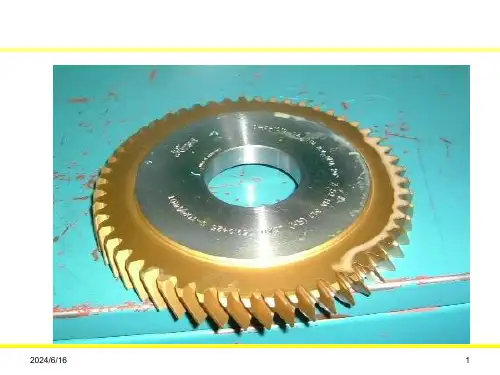
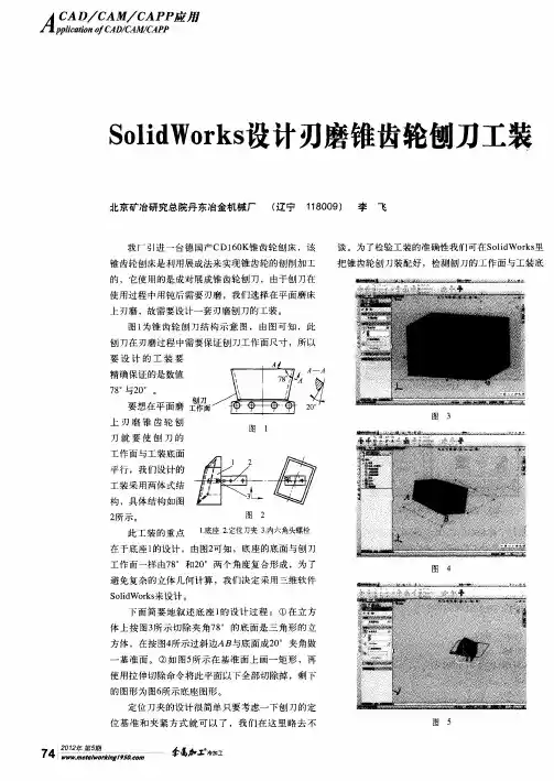
斜齿插齿刀刃磨胎具的设计
- 格式:pdf
- 大小:164.00 KB
- 文档页数:2

毕业论文<设计)题目齿轮内孔磨削夹具的设计系部机械工程系专业机械设计制造及自动化年级 08数控学生姓名曹喻学号 080683038指导教师牟柳晨齿轮内孔磨削夹具的设计机械设计制造及自动化专业学生:曹喻指导教师:牟柳晨【摘要】由于齿轮在飞速发展的现代机械工业中得到了广泛的应用,齿轮传动是重要的传动形式之一,其制造精度,强度,耐磨性等直接影响机器的整体精度和生产使用寿命。
所以在这个工业加工精度不断提高的时代,齿轮加工在机械生产中便成为很重要的一项工作。
但由于齿轮本身形状的特殊性,在加工齿轮时若使用一般的机床夹具则无法满足夹紧要求,使齿轮无法达到精度高,强度大,耐磨性好的制造加工要求。
在齿轮加工中过程中都要进行热处理,齿轮齿面经热处理后不经过热加工会存在一定放的热处理变形,这就导致了基准孔也跟着变形,以致热处理前所做的基准孔在热处理后失去了应有的作用,以齿轮齿面为基准磨削齿轮内孔,是经常用到的加工方法,在此道工序中必须有专用的磨削夹具。
机床夹具设计的主要任务是根据设计任务要求,结合被加工件、金切设备及其切削方式和参数,合理选择定位方式,设计合理的定位支承元件、夹紧装置、对刀元件、夹具体等装置或元件。
夹具设计必须满足一些要求:要保证工件加工的各项技术要求;具有生产效率高和生产成本低廉的特点;尽量选用标准件;具有良好的结构工艺性;同时应该便于操作人员掌握和操作。
而齿轮夹具比较常见的固定式为节圆定位方式。
本次设计旨在设计一种结构简单、操作方便、精度高的节圆固定磨削齿轮内孔的专用夹具。
其设计思路为用分度圆中径定位,中径测量三根滚柱,装入专用的夹紧套中,再装入机床的卡盘中进行加工。
【关键词】齿轮夹具磨削内孔Gear products within hole grinding fixture design【abstract】Because the gear obtained the widespread application in swift development’s modern machinery, the gear drive is one of important transmission forms, its manufacture precision, intensity, wear resistant and so on immediate influence machine's overall precision and production service life. Therefore enhances unceasingly in this industry working accuracy the time, the gear cutting then becomes a very important work in the machinery production. But, if as a result of the gear itself shape's particularity, in processes time the gear uses the common engine bed jig to be unable to satisfy the clamp request, causes the gear to be unable to achieve the precision to be high, the intensity is big, wear resistant good manufacture processing request. In the process must carry on the heat treatment in the gear cutting, the gear tooth face after the heat treatment will not have the heat treatment distortion which after the hot-working will certainly put, this caused the datum hole also with to distort, so that before the heat treatment, did datum hole after the heat treatment has lost the proper function, take the gear tooth face as the datum grinding gear in the hole, was the processing method which used frequently, must have the special-purpose grinding jig in this field of endeavor working procedure. The machine tool's fixture design is the main task of the request, unifies according to the design task by mechanical parts and metal-cutting equipment and its cutting way and parameters and rational selection of localization way, to design the reasonable positioning supporting components, clamping device, the knife components, clip specific devices or components. Fixture design must meet some requirements: to guarantee the technical requirements of the workpiece machining。
编号本科生毕业设计硬质合金插齿刀设计及有限元分析The Design and FEA Of Carbide Cutter学生姓名专业学号指导教师学院二〇一一年六月摘要传统插齿刀的前刀面为锥面或平面,而采用硬质合金材料的插齿刀存在构形精度和抗崩刃能力之间相互制约的弊端。
在加工一定数量的工件后,插齿刀会出现微崩刃和侧刃顶部的急剧磨损现象。
因此,有必要分析插齿加工时插齿刀的应力、应变以及危险点的分布。
本文根据插齿刀的构形方法,在CATIA环境下建立插齿刀参数化实体模型,重点完成了对复杂曲面的建模。
并将实体模型导入CATIA有限元分析模块对侧刃进行插齿主切削力静态分析。
从而得知插齿切削力对硬齿面硬质合金插齿刀的磨损和崩刃影响较小,在主切削力作用下刀尖部位为危险点,齿根部位为次危险点。
分析结果为继续研究硬质合金插齿刀奠定了理论基础。
同时,为了加工应用,利用AutoCAD软件绘制了二维工程图纸。
关键词:硬质合金插齿刀 CATIA实体建模有限元分析AbstractThe traditional shaper cutter’s rake face is taper surface or flat. The use of carbide material leads a drawback that the shaper cutter’s configuration accuracy and ability of anti-chipping restricts each other. After machined a certain number of jobs, micro chipping will appears and the top of side edge will wear rapidly. Therefore, it is necessary to analyze the distribution of shaper cutter’s stress, strain and dangerous point.This article according to the shaper cutter’s configurati on method, established its parametric solid models in the CATIA environment, focus on the completion of the modeling of complex surface. And import solid models into CATIA finite element analysis module for the static analysis of the main cutting force. At last we got the result that the main cutting force has little effect on carbide shaper cutter’s wear and chipping. Under the action of main cutting force the corner is dangerous point, the tooth roots part is the minor dangerous point. The analysis results laid a theoretical foundation of further study of carbide shaper cutter. Meanwhile, for practical application, used AutoCAD software to draw two-dimensional engineering drawings.Keywords: Carbide material; Shaper cutter; CATIA solid modeling; Finite element analysis目录摘要 (1)Abstract (2)目录 (3)第1章绪论 (1)1.1 硬齿面插齿技术概述 (1)1.1.1 插齿技术在齿轮加工中的地位 (1)1.1.2 硬齿面插齿技术的国内外发展现状 (1)1.2 插齿刀技术的发展 (3)1.2.1 涂层技术的开发应用 (3)1.3插齿刀变位系数的限制因素 (3)1.3.1内插齿刀的最大变位系数(X0)max的限制因素 (4)1.3.2内插齿刀的最小变位系数(X0)min 的限制因素 (4)1.4 本课题研究的主要内容 (4)第2章硬质合金插齿刀的建模 (6)2.1 硬质面插齿刀的构形理论 (6)2.2 插齿刀的具体设计参数 (6)第3章 CATIA环境下的插齿刀实体建模 (16)3.1 CATIA软件简介 (16)3.2 曲面造型技术 (17)3.3 凸曲面插齿刀实体建模 (18)3.4 插齿刀实体造型的作用 (23)第4章插齿刀有限元分析 (24)4.1 关于有限元分析法的有关问题 (24)4.2 有限元分析原理及步骤 (26)4.3 插齿刀有限元具体分析过程 (28)4.4 刀齿插齿主切削力受载分析 (32)4.4 总结 (36)结论 (37)参考文献 (38)致谢 (39)第1章绪论1.1硬齿面插齿技术概述随着机械工业的发展,硬齿面齿轮的应用越来越广泛。
内斜齿插齿加工工艺导言:内斜齿插齿加工工艺是一种常用的齿轮加工方法,广泛应用于机械制造领域。
本文将介绍内斜齿插齿加工的原理、工艺流程以及注意事项。
一、内斜齿插齿加工原理内斜齿插齿加工是利用插齿刀在齿轮内孔表面上切削出齿槽的加工方法。
具体原理如下:1. 刀具选择:根据齿轮的模数、压力角和齿轮材料等因素选择合适的插齿刀。
2. 切削速度:根据齿轮材料的硬度和刀具的材质,确定合适的切削速度。
3. 进给量:根据齿轮的齿数、模数和切削速度等因素,确定合适的进给量。
4. 切削力控制:通过控制切削速度、进给量和刀具的刀具几何参数,来控制切削力的大小。
二、内斜齿插齿加工工艺流程内斜齿插齿加工的工艺流程一般包括以下几个步骤:1. 工件准备:选择合适的齿轮材料,按照设计要求进行加工准备工作,如锯切、热处理等。
2. 设计插齿刀:根据齿轮的模数、齿数和压力角等参数,设计出合适的插齿刀。
3. 装夹工件:将齿轮装夹在加工设备上,并进行合适的定位和夹紧。
4. 粗加工:使用插齿刀进行粗加工,切削出齿槽的初步形状。
5. 精加工:使用插齿刀进行精加工,修整齿槽的尺寸和形状,提高齿轮的精度。
6. 清洗和检验:清洗齿轮,去除加工时产生的切屑和油污,进行齿轮的质量检验。
7. 表面处理:根据齿轮的使用要求,进行表面处理,如镀铬、热处理等。
8. 组装:将加工好的齿轮组装到相应的机械装置中,完成整个加工过程。
三、内斜齿插齿加工注意事项在进行内斜齿插齿加工时,需要注意以下几点:1. 插齿刀的选择:根据齿轮的参数选择合适的插齿刀,保证切削效果和加工精度。
2. 切削参数的控制:合理控制切削速度、进给量和切削深度,避免切削过程中产生过大的切削力。
3. 加工设备的选择:根据齿轮的尺寸和加工要求选择合适的加工设备,保证加工精度和效率。
4. 定位和夹紧的准确性:保证齿轮在加工过程中的稳定性和精度,避免加工误差。
5. 齿轮的质量检验:在加工完成后进行齿轮的质量检验,确保加工质量符合要求。
费罗型斜齿插齿刀的特殊设计
张端乐
【期刊名称】《机械设计与制造工程》
【年(卷),期】1993(000)004
【摘要】采用费罗型斜齿插齿刀加工螺旋角大、插齿空刀槽狭窄的阶梯齿轮时,两侧刀刃的高度差往往占据空刀槽宽度的绝大部分,锐侧切削刃出刀时,钝侧切削刃可能撞刀,妨碍排屑和正常切削。
文章提出了两种特殊的斜齿插齿刀设计方案,以降低刀刃高度差。
1.双阶梯前面,保持前角γ不变,但使两侧刀刃分别位于两个阶梯形布列的前面上; 2.带刃倾角λ的斜前面,与插齿刀端面夹角(?)小于螺旋角β,不与齿向垂直,与齿向的垂直面之间有夹角λ,有如顶刃的刃倾角,同时具有径向前角γ。
文章论述了这两种插齿刀的结构特点,计标公式和切削性能,并举出了加工实例以证实其可行性。
【总页数】5页(P15-19)
【作者】张端乐
【作者单位】苏州冶金机械厂邮编215004
【正文语种】中文
【中图分类】TH122
【相关文献】
1.斜齿插齿刀的刃形优化 [J], 刘喜平
2.斜齿外插齿刀优化设计 [J], 王中庆;彭永红
3.费罗型斜齿插齿刀的特殊设计 [J], 张端乐
4.剃前修缘斜齿插齿刀的设计 [J], 刘炎琼;周国兴、郭扬
5.插齿工艺加工倒锥齿插齿刀优化设计 [J], 李敏;吕垚;何猛
因版权原因,仅展示原文概要,查看原文内容请购买。
车刀刃磨器的设计
宫笃篪
【期刊名称】《中国机械》
【年(卷),期】2014(000)022
【摘要】车刀是一种应用非常普遍的金属切削刀具,在现代机械加工行业上,车刀应用的频率是非常高的。
车刀和其它刀具一样,切削一段时间后就会变钝,此时必须对其重磨方可使用。
否则,加工精度和生产效率都受到严重的影响。
车刀刃磨机研究的目的就是提高其刃磨质量,降低制造成本,提高生产率;通过对车刀刃磨的控制研究,实现对车刀的位置几何角度自动调整,提高刃磨质量和效率,减少工人的劳动强度,及时满足生产的需求。
【总页数】2页(P94-95)
【作者】宫笃篪
【作者单位】江苏徐州机电工程高等职业学校
【正文语种】中文
【相关文献】
1.圆弧车刀刃磨的专用夹具设计
2.一种新型车刀钻头刃磨器的设计
3.差速器壳内端面反车刀柄设计与制造的解决方案
4.一种简易可调角度平铣刀刃磨器的设计
5.一种用于车削差速器壳内球面的车刀夹具设计
因版权原因,仅展示原文概要,查看原文内容请购买。