Visio-IN_SIGHT_操作说明
- 格式:pdf
- 大小:14.80 MB
- 文档页数:26

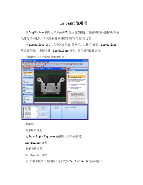
In-Sight说明书该EasyBuilder图形用户界面(GUI)是围绕着图像。
窗格和控制周围的形象被设计为指导建设一个机器视觉应用程序(称为作业)的过程。
该EasyBuilder GUI由六个部分组成:菜单栏,工具栏(标准,EasyBuilder,资源管理器),申请步骤,EasyBuilder查看,调色板和设置窗格。
详情请点击红色的有界的地区之一:菜单栏图形用户界面的In - Sight Explorer的图形用户界面参考EasyBuilder查看电子表格视图EasyBuilder查看注:在菜单栏的下面的例子选项仅当EasyBuilder观是活动窗口。
菜单栏包括以下分支:文件菜单:开始新的就业机会,打开和保存工作或图像。
在打印前预览工作的结果表,打印结果表并退出EasyBuilder硬拷贝。
编辑菜单:撤消和重做操作,请执行选定的工具的图形编辑操作和最大化的地区。
查看菜单:显示或隐藏自定义的图形用户界面后EasyBuilder:在视距网络设置面板,在视线文件窗格中,调色板,工具栏和电影一样。
此外导航到任何可用的EasyBuilder应用步骤或切换到电子表格视图。
图像菜单:购买一个新的形象,显示现场视频图像,记录和回放图像,调整当前图像放大系数,旋转图像,使能/禁用图像中的像素饱和突出。
传感器菜单:拨动了积极的In - Sight传感器联机状态。
配置设置为活动的In - Sight传感器,包括网络设置,日期和时间设置,主机表设置,FTP设置,用户访问和显示的图像设置。
系统菜单:登录(或开来)EasyBuilder。
在一个或更多的视线传感器执行文件操作,包括报表生成,文件备份,文件恢复,克隆和固件更新。
配置新的或现有的In - Sight传感器或设备上进行通信的TCP / IP网络或直接到PC使用添加传感器/设备到网络对话框。
设置安全级别,与其他设备通信子网,保存当前工作的布局和设置EasyBuilder图形用户界面选项。


Installation InstructionsOriginal InstructionsVisiSight Photoelectric Background Suppression Sensors with IO-LinkBulletin Number 42JTDefault SettingsThe factory default settings are as follows:•Sensing Range: Maximum setting •Output Mode: Light operate (Output ON when target detected)•Output Type: Auto PNP/NPN or IO-Link. In Auto PNP/NPN mode, the sensorcontinuously monitors the load connection and automatically configures the output to PNP or NPN.Sensor User InterfaceStatus IndicatorsThe following table provides the state of the status indicators in the RUN mode, during operation. The sensor is always in RUN mode, except when being taught.SpecificationsIMPORTANTSave these instructions for future use.ColorState Description Auto PNP/NPN OperationGreenOFFPower is OFF ON Power is ONFlashing (6 Hz)Unstable light level (0.5 < margin < 2)Flashing (1.5 Hz)Output short circuit protection activeYellow OFF Output de-energized ONOutput energizedIO-Link Operation Green OFF Power is OFF Flashing (1 Hz)Power is ON YellowOFF Output de-energized ONOutput energizedYellow Status IndicatorPush ButtonGreen Status IndicatorAttribute Visible Red (1)42JT-B2LAT1-x 42JT-B2LAT2-x(1)Replace the x with a connection type suffix code from Table 1.Class 1 Laser (1)42JT-B8LAT1-xEnvironmental Certifications cULus Listed, CE Marked for all applicable directives, andUKCA Marked for all applicable regulationsOperating environment IP67, IP69K, ECOLAB (2)(2)ECOLAB on P4 and A2 models only Vibration 10…55 Hz, 1 mm amplitude (meets or exceeds IEC 60947-5-2)Shock30 g with 1 ms pulse duration (meets or exceeds IEC 60947-5-2)Operating temperature -20…+60 °C (-4…+140 °F) (3)(3)UL: -20…+50 °C (-4…+122 °F)Storage temperature -20…+80 °C (-4…+176 °F)OpticalLight sourceRed 660 nm Class 1 650 nmSensing distance (90% reflectivity white) [mm (in.)]1…180 (0.04…7.09) (4)(4)For 42JT-B2LAT1 (180 mm) models 4…150 (0.16…5.91)3…400 (0.12…15.8) (5)(5)For 42JT-B2LAT2 (400 mm) models Sensing distance adjustability [mm (in.)]10…180 (0.4…7.09)12…150 (0.5…5.91)30…400 (1.2…15.8)Sensing distance (18% reflectivity gray) [mm (in.)]2…160 (0.08…6.3) (4)5…150 (0.2…5.91)6…260 (0.24…10.24) (5)Sensing distance (6% reflectivity black) [mm (in.)]4…120 (0.16…4.72) (4)8…120 (0.31…4.72)12…200 (0.5…7.9) (5)Adjustments Push button Electrical Voltage10…30V DC (6)(6)UL: Class 2 sourceCurrent consumption, max 30 mASensor protection Reverse polarity, short circuit overload protectionOutputs Response time 0.5 ms max Output type Auto PNP/NPN or IO-Link Output function Selectable light or dark operateOutput current, max 100 mA Output leakage current, max 10 µA Mechanical Housing material ABS Lens material PMMA Cover material PMMAOptional accessories Mounting brackets, cordsetsTable 1 - Connection TypesSuffix CodeDescription A2 2 m (6.6 ft) cable P4Integral 4-pin pico (M8) QDF44-pin DC micro (M12) QD on 150 mm (6 in.) pigtail Y44-pin pico (M8) QD on 150 mm (6 in.) pigtailVisiSight Photoelectric Background Suppression Sensors with IO-Link Installation InstructionsVisiSight ConfigurationThe 42JT VisiSight™ sensor is configured with the push button, Remote Teach, or via IO-Link and the status indicators on the sensor.Four features can be configured:•Standard or precision teach for sensitivity/sensing range•Light operate (L.O.) or dark operate (D.O.) output•Auto PNP/NPN, dedicated NPN, or dedicated PNP•Push button lock/unlockThe sensor output is disabled during Teach.Teach Sensitivity/Sensing RangeThe default setting is the maximum sensitivity/range.Teaching the sensitivity/sensing range is a two-step process. Teach the background (first condition) and teach target (second condition). Switching threshold for output ON vs. OFF is set in between the two conditions.Standard Teach1.To teach the background (first condition):Align the sensor to the background. Press andhold the button for 3 seconds until yellowstatus indicator starts to flash. Release thebutton. The first condition has now beentaught.2.Teach target (second condition):Insert the target between the sensor and thebackground. Press and release the button.The teach process is complete.If the button is not pressed within30seconds, the sensor exits teach mode andreturns to RUN mode without learning thenew setting.If there is no background surface in the field of viewin step 1, the switching threshold is set between the distance to the target and the maximum sensing range. The sensor can also be taught by teaching the target as the first condition and background as the second condition.Precision TeachFor a more precise setting with a smaller hysteresis, teach the sensor to the target in step 1 and keep the target present in step 2).Restore to Factory Default Setting of Maximum RangePerform step 1 and step 2 with no target in the field of view of the sensor and nothing in the background.Teach Light Operate (L.O.) or Dark Operate (D.O.)The default setting of the output is light operate (L.O.).L.O. setting means that output turns ON when the target is detected. If the application requires the output to turn OFF when the target is detected, the setting may be changed to dark operate (D.O.).1.To access the teach output mode setting:Press and hold button for 6 seconds until thegreen status indicator starts to flash. Releasethe button. The yellow status indicatorindicates the current setting:-L.O.: Yellow status indicator ON- D.O.: Yellow status indicator OFF2.To change the sensor output mode setting:Press and release the push button within tenseconds to toggle from L.O. to D.O., theselection indicated by the yellow statusindicator.The sensor retains the setting per the lastpress of the push button and returns to theRUN mode ten seconds after the last press ofthe push button.Output Type Selection: Auto PNP/NPN, Dedicated NPN, Dedicated PNPThe default setting is Auto PNP/NPN. The sensor monitors the load connection and automatically configures for proper operation (that is, PNP or NPN). If no load is connected, the sensor defaults to PNP. The following applications are covered with dedicated PNP or dedicated NPN selection:•Parallel wiring of multiple sensor outputs: select dedicated PNP or dedicated NPN setting, as needed.•If the load is connected for NPN configuration but to a power supply other than that to the sensor or via a load enabling contact (for example, a relaycontact in series with the load), select dedicated NPN.Selection can be made as follows:•To access output type: Press and hold the push button for 12 seconds (untilboth status indicators start to flash synchronously). When the push buttonis released, the slow flash of the status indicators indicates the currentsetting of output type as follows:-Auto PNP/NPN: Both status indicators flashing-Dedicated NPN: Green status indicator flashing-Dedicated PNP: Yellow status indicator flashing•To change output type: Press and release the push button within10seconds to select desired type. Each button activation cycles to thenext output setting. The status indicators indicate the type that isselected. The sensor retains the setting per the last press of the buttonand returns to the RUN mode 10 seconds after the last press of the button.Push Button Lock/UnlockThe push button or remote teach (RT) can be used to help prevent unauthorizedusers from changing teach settings.horizontally to the optics of the sensor are detected.Targets that travel vertically may not be accuratelydetected. For reliable background suppression, aminimum separation distance is recommendedbetween the target and the background. However, thisdistance can vary depending on the application. SeeTypical Response Curves on page3.IMPORTANT With multiple reflectivity targets, choose the darkest/least reflective target and place it in its farthestposition for setup.Lock/Unlock DescriptionLock the push buttonPress and release the button three times within 3 seconds.Both status indicators flash synchronously for 3 seconds,which indicates that the push button is now locked.Unlock the push buttonPress and release the button three times within 3 seconds.Both status indicators flash asynchronously for 3 seconds,which indicates that the push button is now unlocked.Permanent lock The push button may be permanently locked by connecting thewhite wire (pin 2) to -V.2Rockwell Automation Publication 42JT-IN004B-EN-P - May 2023Rockwell Automation Publication 42JT-IN004B-EN-P - May 20233VisiSight Photoelectric Background Suppression Sensors with IO-Link Installation InstructionsRemote Teach (RT)The sensor can be taught remotely via the white wire (pin 2).Connection to +V acts the same as the button being pressed and no connection is the same as the button not being pressed. The sensor can be taught by following the same teach/timing sequence as used in the push button teach (for example, connect to the +V for more than 3 seconds to teach the target, disconnect from the +V; remove the target and connect to the +V for less than 1 second to teach the No Target condition). All push button functions can also be carried out via RT.IO-LinkSee publication 42JT-UM001 for IO-Link instructions. Remote Teach (pin 2) is disabled in IO-Link operation. If output is selected as dedicated NPN, IO-Link communication is unavailable.Wiring DiagramsThe quick-disconnect connector is shown in Figure 1. The pin numbers correspond to male connectors on the sensor.Figure 1 - Micro (M12) Male QD Pigtail/Integral Pico (M8) Male QDOutput Wiring(1)Normal operation: No connection (disabled in IO-Link operation.)Remote Teach: See Remote Teach (RT) on page 3.Push Button Lock: Connect to -V. See Push Button Lock/Unlock on page 2.Approximate Dimensions [mm (in.)]AccessoriesTypical Response CurvesFigure 2 - Background Suppression (180 mm)Figure 3 - Background Suppression (180 mm Spot Size)(1)The spot is square in shape with one side dimension per graph.2M8 MaleOutput: Auto PNP/NPN or IO-Link Remote Teach/Lock (1)+V-VBrown (1)White (2)Black (4)Blue (3)2.8Table 2 - Stainless Steel Mounting Brackets5101520321200(7.87)150(5.91)100(3.94)50(1.96)Distance [m (ft)]% o f d i s t a n c e1Black/white shift 6/90%2Gray/white shift 18/90%3Hysteresis 90/90%51015200(7.87)150(5.91)100(3.94)50(1.96)Distance [mm (in.)]S i z e [m m ] (1)Publication 42JT-IN004B-EN-P - May 2023 | Supersedes Publication 42JT-IN004A-EN-P - May 2014Copyright © 2023 Rockwell Automation, Inc. All rights reserved. Printed in the U.S.A.Rockwell Otomasyon Ticaret A.Ş. Kar Plaza İş Merkezi E Blok Kat:6 34752, İçerenköy, İstanbul, Tel: +90 (216) 5698400 EEE Yönetmeliğine UygundurAllen-Bradley, expanding human possibility, Rockwell Automation, and VisiSight are trademarks of Rockwell Automation, Inc.Trademarks not belonging to Rockwell Automation are property of their respective companies.068-1454810000212180 Ver 04Waste Electrical and Electronic Equipment (WEEE)Rockwell Automation maintains current product environmental compliance information on its website at rok.auto/pec .At the end of life, this equipment should be collected separately from any unsorted municipal waste.Your comments help us serve your documentation needs better. If you have any suggestions on how to improve our content, complete the form at rok.auto/docfeedback .For technical support, visit rok.auto/support .Figure 4 - Background Suppression (400 mm)Figure 5 - Background Suppression (400 mm Spot Size)(1)The spot is square in shape with one side dimension per graph.Figure 6 - Laser Background Suppression (150 mm)Figure 7 - Laser Background Suppression (120 mm Spot Size)The minimum distance that is required between the target and the background depends upon the taught sensing range and the reflectivity of the target and background. The curves can be used as a guide in a given application.Example (for 400 mm model): at around 230 mm taught sensing range, an 18%reflectivity gray target must be at least 5%, that is, 12 mm away from a 90%reflective white background.5101520321200(7.87)400(15.7)100(3.94)300(11.8)Distance [mm (in.)]% o f d i s t a n c e1Black/white shift 6/90%2Gray/white shift 18/90%3Hysteresis 90/90%0510152025300200(7.87)400(15.7)100(3.94)300(11.8)Distance [mm (in.)]S i z e [m m ] (1)Distance [mm (in.)]% o f d i s t a n c e1Black/white shift 6/90%2Gray/white shift 18/90%3Hysteresis 90/90%(1.18)(2.36)(3.54)(4.72)(5.91)10.0.1.1.2.2.3.(1.18)(2.36)(3.54)(4.72)(5.91)Distance [mm (in.)]S i z e [m m ] (1)。
福建工程学院软件人才培养基地参考资料Visio使用手册福建宏天信息产业有限公司福建工程学院软件人才培养基地2006年3月文档信息下表汇总了Visio使用手册的版本、撰写人及审阅人。
目录1.1M ICROSOFT V ISIO简介 (1)1.2M ICROSOFT V ISIO P ROFESSIONAL 2002中文版基本使用 (1)1.2.1 主界面介绍 (1)1.2.2 基本使用 (2)1.2.3 常用绘图类型 (4)1.1Microsoft Visio简介Microsoft Visio 是独立的图表解决方案,它可以帮助用户交流创意、信息和系统并将其可视化。
使用Visio 可以定义和记录日常工作生活的复杂信息,并与其他人有效地共享创意和信息。
另外,如果将Visio 图表合并到Office 文档中,将使信息变得更简洁、让别人更容易记住要点、更容易克服文化和技术上的障碍。
Visio 有三个主要作用:补充Microsoft Office 业务。
专业人员可以创建信息丰富的图表,以便补充和扩展他们用Office 程序所做的工作。
简化技术设计、部署和维护。
技术专业人员可以用图表记录创意、信息和系统,以便简化IT 部署、扩展开发工具的使用,甚至记录设备布局和工程计划。
支持开发自定义的可视解决方案。
Visio 使用户能够创建自定义的形状和模具来支持组织标准,还可以用来创建范围广泛的自定义可视解决方案。
Visio 家族包括能够满足特定用户组需要的三种产品:Microsoft Visio Standard 提供了图表解决方案,帮助业务专业人员(例如项目经理、销售和市场专业人员、HR 人员、管理人员和其他人)共享日常接触的人员、项目和进程等方面的信息并对其进行可视化Microsoft Visio Professional 帮助技术专业人员(IT、开发人员和工程专业人员)对现有的创意、信息和系统进行可视化,并建立新创意、信息和系统的原型。
visio使用手册---网络拓扑图的利器2008-10-29 11:44:41标签:visio拓扑图前言全球化、并购和管理制度的重建显然是现今商业界的主要潮流。
若要在其中取得一席之地、站稳自己脚步,企业组织便不能再像过去一样只是守成而已。
更重要的是必须能迅速地跟上市场的变化、满足其多样化的需求,并要求员工随时存取即时的资讯,也难怪越来越多的企业都觉得现有的通讯架构已不能完全负荷它们的业务需求了。
当企业组织企图寻找一种既无法掌握又充满理想的通讯工具时,常常会忽略其中一个最有效分享资讯的方法:视觉化。
现在,我们都会直觉地认为以有效的绘图表现讯息,会比任何书面文件更能清楚地传递想法、过程或程序。
人类往往会本能地视觉化问题的解答,您是否曾注意到,「我看到 (I see)」和「我了解(I understand)」是相同的意思呢?此外,正确的视觉化表现方式还能跨越部门、语言、文化与地理界线通讯等限制。
就现今的商业交易速度而言,视觉化通讯的重要性是无可比拟的,成功的企业组织需要一个好用的工具以接收及沟通企业里的资讯。
就视觉通讯的软体而言,Microsoft Visio 2000就是这种工具,它能提供清楚的认知,让我们迅速地达成共识。
认识Visio它是一种把流程视觉化的软体,目的在使我们能轻易地把资料转换成图形Visio从1990年开始发展,至今全球已经有叁百多万位使用者了。
产品线分成四个版本:标准版、工程版、专业版以及企业版。
Microsoft Visio 2000提供了弹性的解决方案—从後端办公室到角落办公室,它的操作介面相容於Windows作业系统,能让每个人快速地上手,此外,可延伸的架构更提供了十分完善的自订化功能给特定的工作者。
让每个人都获得好处的易用工具企业组织需要建置适合初学者使用的工具,但同时又要能符合进阶使用者的需求。
Visio 2000的拖曳技术能帮助初学者立即上手,不必担心没有能力达到老板的要求,或要花很多时间在制作图形上,而分级制的进阶功能则可以让进阶使用者的才能发挥得淋漓尽致。
In-Sight操作说明一、语言转换介绍:点击菜单栏->System->Options,请看以下弹出以下对话框点击User Interface,将以上下拉框的English改为Chinese,点击OK,弹出以下对话框点击OK ,然后退出In-Sight 软件,再重新启动In-Sight 软件,显示以下中文界面:二、界面整体介绍:1:菜单栏2:In-Sight 网络:主要显示网络上的相机3413:电子表格:用来写程序的4:选择板:显示视觉工具,编程时,可以拖拉此选项板的工具进行写程序In-Sight网络和选择板可以在菜单栏->查看选择In-Sight网络或选择板显示或不显示这2个显示板二、视觉工具介绍:点击电子表格中的A2,如下所示A2ExtractBlobsa.选择板->视觉工具->斑点->双击弹出以下对话框属性设置固定:定位用的,可引用定位工具结果,点开“+”号,双击行,在电子表格选择你要引用的行定位结果,双击列,在电子表格选择你要引用的列定位结果,双击角度,在电子表格选择你要引用的角度定位结果;区域:可以自己定义,也可以引用其他工具结果,若引用其他工具结果,与固定引用方法一样设置,双击每一个要引用的参数,再进入电子表格选择你要引用的结果;若自己定义,可以双击区域,然后拖拉搜索框的大小,再在搜索框内双击进入到设置属性界面;所有参数设置外后按确定即可。
b.点击电子表格其他单元,选择板->视觉工具->边->双击FindLine弹出以下对话框属性设置例c. 点击电子表格某单元格,选择板->视觉工具->图案匹配->双击FindPatterns弹出以下对话框属性设置。
In_Sight操作步骤1.打开软件,查看—添加In_Sight网络,在左侧出现In_Sight 传感器栏,如图1.1:图1.1右击In_Sight传感器—添加传感器---弹出添加网络窗口(图1.2),此时会自动弹出相机型号---点击右侧使用下列网络设置可以设置相机IP地址---点击应用即可。
图1.2连接完成后,出现如图1.3界面:图1.32. 设置程序文件:如图2.1图2.12.1.点击图2.1中的设置图像---左下角出现采集/加载图像窗口,如图2.1.1图2.1.1编辑采集设置:触发器:触发采集照片的信号来源曝光:可适当调大或调小其他参数不要动,都采用默认点击实况视频---在图像界面可以看到实时图像---将相机和产品位置调整好---双击实时图像即可拍一张照片—如图2.1.2:图2.1.22.2 点击图2.1中的检查部件---左下角出现添加工具窗口,如图2.2.1:图2.2.1点击产品识别工具----颜色,如图2.2.2:图2.2.2点击添加—在右侧窗口出现区域类型选项,如图2.2.3,同时在刚拍的照片上出现一个紫色小方框,如图2.2.4:图2.2.3图2.2.4区域类型后的下拉菜单可以选择区域类型,此处选择矩形,则在2.2.4中出现方框符号,如果区域类型选择圆,则在2.2.4中出现的就是一个圆形的粉红色符号。
将2.2.4中粉红色方框移动到要检测的区域内,如图2.2.5:图2.2.5点击图2.2.3中的OK按钮此时在右侧选择板出现如图2.2.6图2.2.6同时在窗口下侧出现常规设置窗口:如图2.2.7:图2.2.7点击训练颜色—弹出窗口2.2.8:图2.2.8点击加上新颜色上方的方框按钮,点击加上新颜色—在图像中拖动刚才选择的粉色小方框到检测区域----双击鼠标左键,弹出窗口2.2.9---点击确定,在窗口下册即添加成功,如图2.2.10图2.2.9图2.2.10在图2.2.10中,Color_1前打钩,此时图像中的选择小方框变为绿色,如图2.2.11:图2.2.11拖动小方框到别的区域,小方框即变为红色,说明设置成功。