PV10-Large BIPV System-A
- 格式:pdf
- 大小:235.73 KB
- 文档页数:2

学士学位论文PV-Trombe墙系统的实验研究Experimental Study on PV-Trombe Wall System2022年4月26日目录摘要 (2)Abstract (3)第1章绪论 (4)第1节太阳能光伏与光热技术 (4)第2节太阳能光伏建筑一体化与光热建筑一体化 (7)第3节太阳能光伏光热建筑一体化 (9)第2章PV-Trombe墙系统 (13)第1节PV-Trombe墙系统的工作原理 (13)第2节PV-Trombe墙系统的数学模型 (17)第3章PV-Trombe墙的实验设计与性能探究 (23)第1节试验设计与试验安排 (23)第2节实验综合分析 (25)全文小结 (35)参考文献 (35)摘要在能源紧缺,资源告急,环境污染日益严重的今天,充分利用太阳能是解决当今社会一系列不和谐问题的十分有效的途径之一。
最近几年,在新能源利用领域,光伏技术迅速发展,无论在光电转换效率、市场占有率还是在价格定位等方面都有新的突破,但是该技术距离达到广泛而普遍的运用以及与其他技术的结合还有相当长的一段路要走,比如光伏光热相结合技术、光伏光热建筑一体化技术等等。
然而,至于BIPV技术,现有的研究主要集中于提高光伏模块本身的光电效率,并没有在意其副产品的有效利用,如热水或热空气等系统冷却流体。
另外,经济性也是BIPV 系统的应用中应该考虑的问题。
因而作为科研工作者我们务必在提高BIPV系统的功能性的同时还要进一步降低产品的实际成本。
对此,本文对“光伏光热建筑一体化(BIPV/T)系统”这种应用太阳能同时发电供热的新系统进行一番详细介绍,并着重对其中的PV-Trombe墙进行具体而全面的研究。
BIPV/T 系统实质上是在建筑围护结构外表面铺设光伏模块或直接取代外围结构,并在模块背面采取水冷或风冷模式,且对流体带走的热量加以利用,同时产生电、热俩种能量收益,提高了系统的太阳能综合利用效率。
而组成BIPV/T系统的重要组成部分之一——新型PV-Trombe墙,我们结合在光伏电池模块的背面铺设流道、通过流体带走热量的思想,提出一种新的太阳能光伏光热建筑一体化方案:在Trombe墙的玻璃盖板背面贴上光伏电池就构成了新型的带有光伏电池的Trombe墙,即PV-Trombe墙。

bipv案例BIPV (Building Integrated Photovoltaics) is a technology that integrates solar panels into building materials, such as windows, roofs, and facades, to generate electricity. Here are a few BIPV case studies:1. King Abdullah University of Science and Technology (KAUST) Solar Village, Saudi Arabia:Located in Thuwal, Saudi Arabia, the solar village at KAUST is equipped with BIPV technologies. The project includes solar panels integrated into canopies, facades, and roofs of various buildings within the village. The BIPV installations reduce the reliance on fossil fuels and provide a sustainable energy source for the community.2. SinBerBEST (Sustainable and Integrated Buildings for Energy Systems and Technologies) Project, Singapore:The SinBerBEST project in Singapore is dedicated to developing and implementing sustainable building technologies. One of the focus areas is BIPV integration into building facades. The project aims to optimize solar energy generation while maintaining building aesthetics and functionality.3. The Edge, Amsterdam, Netherlands:The Edge, an office building in Amsterdam, is considered one of the world's greenest buildings. The building's facade incorporates thousands of BIPV solar panels, making it nearly energy-neutral. The BIPV system enables the building to generate its electricity and also provides shading to reduce the need for air conditioning.4. Masdar City, Abu Dhabi, UAE:Masdar City is a sustainable urban development in Abu Dhabi. It incorporates various renewable energy technologies, including BIPV. The city features buildings with integrated solar panels that generate clean energy for the community. The BIPV systems help reduce the overall carbon footprint and contribute to a more sustainable city.5. Sistine Solar Project, Boston, USA:The Sistine Solar project focuses on developing customized solar panels with designs that blend visually into the building facades. The project aims to improve the architectural integration of solar panels and promote wider adoption of BIPV technologies. By integrating solar panels that resemble traditional building materials, such as shingles or tiles, the project enhances the aesthetics of solar installations.These are just a few examples of BIPV installations around the world. With the constant advancements in solar technology and increased emphasis on sustainable construction, BIPV is expected to become more prevalent in the future.。
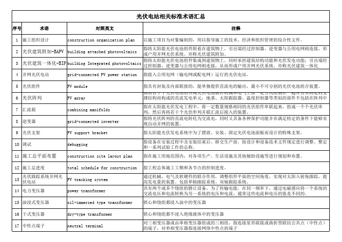
序号术语对照英文注释1施工组织设计construction organization plan以施工项目为对象编制的,用以指导施工的技术、经济和组织管理的综合性文件。
2光伏建筑附加-BAPV building attached photovoltaics 指将太阳能光伏电池组件附着在建筑物上,引出端经过控制器、逆变器与公用电网相连接,形成户用并网光伏系统。
亦称光伏建筑附加。
3光伏建筑一体化-BIPV building Integrated photovoltaics 指将太阳能光伏电池组件集成到建筑物上,同时承担建筑结构功能和光伏发电功能;引出端经过控制器、逆变器与公用电网相连接,从而形成户用并网光伏系统。
亦称光伏建筑一体化4并网光伏电站grid-connected PV power station指接入公用电网(输电网或配电网)运行的光伏电站。
5光伏组件PV module指具有封装及内部联接的,能单独提供直流电的输出,最小不可分割的光伏电池组合装置。
6光伏阵列PV array 指由若干个光伏电池组件或光伏电池板在机械和电气上按一定方式组装在一起并且有固定的支撑结构而构成的直流发电单元,地基、太阳跟踪器、温度控制器等类似的部件不包括在阵列中7汇流箱combining manifolds 指在太阳能光伏发电工程中,将一定数量规格相同的光伏组件串联起来,组成一个个光伏串列,然后再将若干个光伏串列并联汇流后接入的装置。
8逆变器grid-connected inverter 指将光伏阵列的直流电转化为交流电,同时又具备各种保护功能并在满足特定的条件下能够实现自动并网的装置。
9光伏支架PV support bracket指太阳能光伏发电系统中为了摆放、安装、固定光伏电池面板而设计的特殊支架。
10调试debugging 指设备在安装过程中及安装结束后、移交生产前,按设计和设备技术文件规定进行调整、整定和一系列试验工作的总称。

Building Integrated Photovoltaics (BIPV)IntroductionBIPV is the integration of photovoltaics (PV) into the building envelope. The PV modules serve the dual function of building skin—replacing conventional building envelope materials—and power generator. By avoiding the cost of conventional materials, the incremental cost of photovoltaics is reduced and its life-cycle cost is improved. That is, BIPV systems often have lower overall costs than PV systems requiring separate, dedicated, mounting systems.A complete BIPV system includes:a. the PV modules (which might be thin-film or crystalline, transparent, semi-transparent, or opaque);b. a charge controller, to regulate the power into and out of the battery storage bank (in stand-alone systems);c. a power storage system, generally comprised of the utility grid in utility-interactive systems or, a number of batteries in stand-alone systems;d. power conversion equipment including an inverter to convert the PV modules' DC output to AC compatible with the utility grid;e. backup power supplies such as diesel generators (optional-typically employed in stand-alone systems); andf. appropriate support and mounting hardware, wiring, and safety disconnects.BIPV systems can either be interfaced with the available utility grid or they may be designed as stand-alone, off-grid systems.Design of a BIPV SystemBIPV systems should be approached to where energy conscious design techniques have been employed, and equipment and systems have been carefully selected and specified. They should be viewed in terms of life-cycle cost, and not just initial, first-cost because the overall cost may be reduced by the avoided costs of the building materials and labor they replace. Design considerations for BIPV systems must include the building's use and electrical loads, its location and orientation, the appropriate building and safety codes, and the relevant utility issues and costs.Steps in designing a BIPV system include:1. Carefully consider the application of energy-conscious design practices and/or energy-efficiency measures to reduce the energy requirements of the building.2. Choose Between a Utility-Interactive PV System and a Stand-alone PV System.3. Shift the Peak: If the peak building loads do not match the peak power output of the PV array, it may be economically appropriate to incorporate batteries into certain grid-tied systems to offsetthe most expensive power demand periods. This system could also act as an uninterruptible power system (UPS).4. Provide Adequate Ventilation: PV conversion efficiencies are reduced by elevated operating temperatures. This is truer with crystalline silicon PV cells than amorphous silicon thin-films. To improve conversion efficiency, allow appropriate ventilation behind the modules to dissipate heat.5. Evaluate Using Hybrid PV-Solar Thermal Systems: As an option to optimize system efficiency, a designer may choose to capture and utilize the solar thermal resource developed through the heating of the modules. This can be attractive in cold climates for the pre-heating of incoming ventilation make-up air.6. Consider Integrating Daylighting and Photovoltaic Collection: Using semi-transparent thin-film modules, or crystalline modules with custom-spaced cells between two layers of glass, designers may use PV to create unique daylighting features in façade, roofing, or skylight PV systems.7. Incorporate PV Modules into Shading Devices: PV arrays conceived as "eyebrows" or awnings over view glass areas of a building can provide appropriate passive solar shading. When sunshades are considered as part of an integrated design approach, chiller capacity can often be smaller and perimeter cooling distribution reduced or even eliminated.8. Design for the Local Climate and Environment: Designers should understand the impacts of the climate and environment on the array output. Cold, clear days will increase power production, while hot, overcast days will reduce array output.9. Address Site Planning and Orientation Issues: Early in the design phase, ensure that your solar array will receive maximum exposure to the sun and will not be shaded by site obstructions such as nearby buildings or trees. The impact of shading on a PV array has a much greater influence on the electrical harvest than the footprint of the shadow.10. Consider Array Orientation: Different array orientation can have a significant impact on the annual energy output of a system, with tilted arrays generating 50%-70% more electricity than a vertical façade.11. Reduce Building Envelope and Other On-site Loads: Minimize the loads experienced by the BIPV system. Employ daylighting, energy-efficient motors, and other peak reduction strategies whenever possible.12. Professionals: The use of BIPV is relatively new. Ensure that the design, installation, and maintenance professionals involved with the project are properly trained, licensed, certified, and experienced in PV systems work.In addition, BIPV systems can be designed to blend with traditional building materials and designs, or they may be used to create a high-technology, future-oriented appearance. Semi-transparent arrays of spaced crystalline cells can provide diffuse, interior natural lighting. High profile systems can also signal a desire on the part of the owner to provide an environmentally conscious work environment.。

太阳能光伏系统专业词汇中英太阳电池solar cell将太阳辐射能直接转换成电能的器件单晶硅太阳电池single crystalline silicon solar cell以单晶硅为基体材料的太阳电池多晶硅太阳电池so multi crystalline silicon solar cell以多晶硅为基体材料的太阳电池非晶硅太阳电池amorphous silicon solar cell用非晶硅材料及其合金制造的太阳电池。
薄膜太能能电池Thin-film solar cell用硅、硫化镉、砷化镓等薄膜为基体材料的太阳电池。
这些薄膜通常用辉光放电、溅射、真空蒸镀等方法制得。
多结太阳电池multijunction solar cell由多个p-n结形成的太阳电池。
化合物半导体太阳电池compound semiconductor solar cell| 用化合物半导体材料制成的太阳电池带硅太阳电池silicon ribbon solar cell用带状硅制造的太阳电池光电子photo-electron由光电效应产生的电子。
太阳电池的伏安特性曲线I-V characteristic curve of solar cell受光照的太阳电池,在一定的辐照度和温度以及不同的外电路负载下,流入的电流压V的关系曲线。
短路电流short-circuit current (Isc)在一定的温度和辐照度条件下,光伏发电器在端电压为零时的输岀电流。
开路电压open-circuit voltage (Voc)在一定的温度和辐照度条件下,光伏发电器在空载(开路)情况下的端电压。
最大功率maximum power (Pm)| 在太阳电池的伏安特性曲线上,电流电压乘积的最大值。
最大功率点maximum power point| 在太阳电池的伏安特性曲线上对应最大功率的点,亦称最佳工作点。
最佳工作点电压optimum operating voltage (Vn)太阳电池伏安特性曲线上最大功率点所对应的电压。
第52卷第11期2023年11月人㊀工㊀晶㊀体㊀学㊀报JOURNAL OF SYNTHETIC CRYSTALS Vol.52㊀No.11November,2023Li 原子和Ca 原子修饰VO 2单层储氢性能的第一性原理研究侯茵茵,马良财(宁夏大学物理学院,银川㊀750021)摘要:具有高储氢容量和可逆储氢性能的新材料的开发对氢能的大规模利用至关重要㊂基于第一性原理计算,研究了Li 原子和Ca 原子单独修饰和共修饰VO 2单层体系的H 2分子存储性能㊂结果表明Li 原子和Ca 原子均能稳定结合在VO 2单层表面而不产生金属团簇㊂单个Li 原子和Ca 原子分别最多可稳定吸附3个和6个H 2分子,且H 2分子平均吸附能均大于0.20eV /H 2㊂吸附体系差分电荷和态密度分析结果表明,氢分子的极化机制以及氢分子与金属原子间的轨道杂化作用是H 2分子在金属原子周围稳定吸附的主要原因㊂Li 原子修饰体系的储氢质量密度随着Li 原子覆盖度的增加而逐渐增加,而Ca 原子修饰体系的储氢质量密度在低金属覆盖度时较高;Li /Ca 共修饰体系的储氢质量密度有所增加,其储氢质量密度为5.00%(质量分数)㊂此外,考虑了不同温度和压强条件下储氢体系的稳定性㊂关键词:VO 2单层;储氢;第一性原理计算;锂原子;钙原子;修饰中图分类号:O469㊀㊀文献标志码:A ㊀㊀文章编号:1000-985X (2023)11-2014-10First-Principles Study on Hydrogen Storage Performance of Li-and Ca-Decorated VO 2MonolayerHOU Yinyin ,MA Liangcai(College of Physics,Ningxia University,Yinchuan 750021,China)Abstract :The exploitation of new hydrogen storage materials with high-capacity and reversible performance could play a very important role in the large-scale utilization of hydrogen as an energy source.The hydrogen storage performances of Li and Ca atoms decorated as well as Li /Ca co-decorated VO 2monolayer system were comprehensively investigated based on first-principles calculations.The metal atoms are stably adsorbed on the surface of the VO 2monolayer without forming metal clusters.Three and six hydrogen molecules can be absorbed by a Li atom and Ca atom,respectively,and its average adsorption energy is larger than 0.20eV /H 2.Charge density differences and density of states of H 2adsorbed systems were analyzed,and the results reveal that both the polarization mechanism and orbital hybridization are responsible for the adsorption of hydrogen molecules.The hydrogen storage capacity of the Li-decorated system increases with the increase of Li coverage,while that of Ca-decorated system is high only in lower Ca coverage.Moreover,Li /Ca co-decoration can effectively increase the hydrogen storage capacity of the system,its hydrogen storage mass density is 5.00%(mass fraction).Finally,the influence of temperature and pressure on the stability of hydrogen adsorption system is studied.Key words :VO 2monolayer;hydrogen storage;first-principle calculation;lithium atom;calcium atom;decoration㊀㊀收稿日期:2023-05-11㊀㊀基金项目:宁夏自然科学基金(2022AAC03003)㊀㊀作者简介:侯茵茵(1998 ),女,广西壮族自治区人,硕士研究生㊂E-mail:houyinyin2021@ ㊀㊀通信作者:马良财,博士,教授㊂E-mail:maliangcai@0㊀引㊀㊀言随着社会的不断发展,人们所面临的能源危机和环境污染问题日益严重㊂为此,开发和利用清洁㊁高效的新能源并研究其转化与存储技术迫在眉睫[1]㊂氢能具有质量轻㊁储量丰富㊁能量密度大和清洁无污染等㊀第11期侯茵茵等:Li 原子和Ca 原子修饰VO 2单层储氢性能的第一性原理研究2015㊀优点[2],是化石燃料的理想替代能源㊂然而,传统的低温液化或高压压缩等储氢方式存在高成本㊁低密度和低安全性等缺点,使得氢能的大规模应用受到限制(如氢能源汽车)㊂因此,开发利用高效㊁安全㊁经济的储氢新材料成为氢能源发展的关键[3-4]㊂二维纳米材料具有较大的表面积,被认为是一种潜在的高效储氢材料[5],然而,早期的研究发现,氢气在本征二维纳米材料表面的吸附能较低(小于0.10eV/H 2),难以达到理想储氢吸附能范围(0.20~0.40eV/H 2)[6]㊂进一步的研究发现,利用金属原子修饰二维纳米材料表面后,H 2分子的吸附能和体系的储氢密度均得到了大幅提升[7-13]㊂二维石墨烯在储氢领域得到了广泛的研究[8],且金属原子修饰石墨烯体系可实现室温条件下的可逆储氢[8-11]㊂然而,石墨烯与金属原子间的相互作用较弱,当金属原子在石墨烯单层两侧同时吸附时,石墨烯的单层平面构型使得金属原子的结合能进一步降低,易于导致金属团簇的形成,而金属团簇的形成将使得体系储氢密度大幅减小㊂石墨烯在储氢方面的优势和存在的不足,激励科研工作者寻找其他合适的二维储氢材料㊂由于具有良好的光学和电子学特性,以及表面积大和质量轻等优点,二维过渡金属氧化物和硫化物单层材料成为潜在的储氢材料㊂二维过渡金属氧化物和硫化物单层为三层原子构成的三明治结构,中间为过渡金属单原子层,两侧为S 或O 单原子层,因此,当外来金属原子吸附在其两侧表面时,金属原子仅与其同侧的S 或O 原子发生相互作用,金属修饰体系的结合能将大幅增强,有效降低金属团簇形成的可能性,从而提高储氢量㊂Putungan 等[12]研究了金属Li 原子修饰二硫化钼(MoS 2)单层体系的储氢性能,结果表明Li 原子在MoS 2单层表面的结合能大幅增强,体系储氢质量密度为4.40%(质量分数)㊂Song 等[13]对Ca 原子修饰MoS 2单层体系储氢性能进行了研究,发现Ca 原子覆盖度较低时体系具有较好的储氢性能㊂二维二氧化钒(VO 2)纳米单层作为一种新型过渡金属氧化物材料,其优异的热稳定性㊁磁性和光学特性得到了广泛的研究[14-16],在Li㊁Na 和Mg 离子电池负极材料方面具有潜在的应用前景[17]㊂然而,VO 2纳米单层在储氢方面的研究尚未有相关报道,本文通过第一性原理计算方法,探讨了Li 和Ca 原子单独修饰和共修饰VO 2单层体系的储氢性能和储氢机理㊂1㊀计算方法本文的第一性原理计算采用基于平面波基组和投影缀加波(PAW)方法的VASP 软件包[18-19],平面波截断能为500eV,采用PBE 泛函来描述电子间的交换关联势[20]㊂选用DFT-D2方法对H 2分子吸附体系中的范德瓦耳斯作用进行修正[21]㊂基于周期性边界条件,垂直VO 2纳米单层表面方向填充厚度为0.16nm 的真空层,以消除相邻单层间的相互作用㊂布里渊区积分k 点取为8ˑ8ˑ1㊂结构优化时,体系能量和原子受力收敛值分别为1ˑ10-5eV 和0.20eV /nm㊂金属原子与VO 2单层的结合能E b 定义为E b =(E VO 2+mE M -E m M /VO 2)/m (1)式中:E m M /VO 2和E VO 2分别为金属原子M(M =Li,Ca)修饰VO 2单层体系和本征VO 2单层体系的总能量,E M 为单个金属原子的能量,m 为金属原子的数目㊂H 2分子的吸附性能可通过连续吸附能E con 和平均吸附能E ave 来描述,计算公式为E con =E ((n -1)H 2+m M /VO 2)+E H 2-E (n H 2+m M /VO 2)(2)E ave =(E m M /VO 2+nE H 2-E (n H 2+m M /VO 2))/n (3)式中:E ((n -1)H 2+m M /VO 2)和E (n H 2+m M /VO 2)分别为(n -1)个H 2分子吸附体系和n 个H 2分子吸附体系的总能量,n为吸附H 2分子数目,E H 2为自由H 2分子的能量㊂2㊀结果与讨论2.1㊀VO 2单层的电子特性和稳定性结构优化后VO 2单层单胞的平衡态晶格常数为0.274nm,对应的V O 键长为0.195nm,上㊁下两O 原子层的间距为0.228nm,与前人的计算结果一致[14-17]㊂为了明确计算体系的大小对计算结果的影响,以单2016㊀研究论文人工晶体学报㊀㊀㊀㊀㊀㊀第52卷个Li原子修饰尺寸不同的(2ˑ2)㊁(3ˑ3)和(4ˑ4)VO2单层超胞为例,计算了Li原子与VO2单层间的结合能和后续单个H2分子的吸附能,计算结果见表1㊂相对于更大尺寸的(4ˑ4)超胞体系,当采用包含9个V原子和18个O原子的(3ˑ3)超胞体系时,Li原子的结合能和H2分子的吸附能变化不大,而当采用较小尺寸的(2ˑ2)超胞体系(包含4个V原子和8个O原子)时,Li原子结合能和H2分子吸附能均有明显的减小,这是由于超胞尺寸较小时,相邻Li原子间相互作用明显增强㊂因此本文采用(3ˑ3)VO2超胞体系作为计算模型,其几何结构如图1(a)所示㊂VO2单层的能带结构如图1(b)所示,自旋向上与向下能带分布中均有能带穿过费米能级,表明VO2单层具有金属性,且自旋向上和向下能带分布具有不对称性,表明VO2单层具有磁性,计算得到VO2单层单胞体系的磁矩为0.66μB,与前人计算结果一致[17]㊂VO2单层在常温条件下的稳定性是其进行储氢应用的先决条件,为此计算了VO2单层的声子谱,结果如图1(c)所示,其声子谱中没有出现明显的虚频,因此VO2单层具有良好的动力学稳定性[16]㊂进一步采用从头算分子动力学(AIMD)模拟了VO2单层在500K下的热力学稳定性,模拟时间步长为1fs,模拟总时长为5ps,体系总能量随时间的变化趋势如图1(d)所示,在整个模拟时间内,VO2单层的总能量仅在很小的范围内发生波动,没有发生大幅度涨落,且VO2单层的末态结构几乎没有明显的变形,进一步表明VO2单层在高温条件下具有优异的结构稳定性㊂表1㊀不同大小VO2单层超胞的晶格常数㊁Li原子结合能和H2分子吸附能Table1㊀Lattice constant of VO2supercell with different dimensions,the binding energy(E b)of Li atom and theadsorption energy(E ave)of single H2moleculeSupercell Lattice constant/nm E b/eV E ave/eV2ˑ20.548 5.080.2223ˑ30.822 5.360.2554ˑ4 1.096 5.380.260图1㊀VO2单层的优化几何结构㊁能带结构和声子谱,以及AIMD模拟中总能量随时间的变化趋势(T=500K)Fig.1㊀Optimized geometry structure,band structure,phonon spectrum of VO2monolayer,and the variations of totalenergy versus time for the VO2monolayer in AIMD simulation at500K2.2㊀Li原子和Ca原子修饰VO2单层金属原子修饰VO2单层时,考虑了4个不同的金属原子吸附位点,如图1(a)所示,分别为六原子环中心位(H)㊁V O键桥位(B)㊁V原子顶位(T V)和O原子顶位(T O)㊂结构优化后发现Li原子和Ca原子的最稳定吸附位点均为H位,结合能分别为5.36和5.78eV,远大于其相应金属原子的体相内聚能(Li:1.63eV, Ca:1.84eV),修饰体系中Li原子和Ca原子与单层表面的距离分别为0.118和0.151nm,为了便于表述,将金属原子修饰VO2单层体系标记为M/VO2(M=Li㊁Ca)㊂进一步考虑了金属原子在单层表面的动力学稳定性,利用微动弹性带方法(CI-NEB)模拟计算了金属原子从最稳定吸附位点(H位)开始,途经T O位扩散到邻近的次稳定吸附位(T V位)的扩散势垒,如图2所示,在金属原子扩散过程中,Li/VO2体系中存在约为0.70eV的势垒,而Ca/VO2体系中存在约为1.18eV的势垒㊂当金属原子覆盖度增加时,较大的扩散势垒表㊀第11期侯茵茵等:Li 原子和Ca 原子修饰VO 2单层储氢性能的第一性原理研究2017㊀图2㊀Li 原子和Ca 原子在VO 2单层表面的扩散路径和扩散势垒Fig.2㊀Diffusion pathway and energy barrier profile for Li and Ca atom migrate on the surface of VO 2monolayer明稳定吸附于VO 2单层表面的金属原子不易发生扩散,从而可有效避免金属团簇的形成,有利于吸附更多氢分子㊂为了分析金属原子与VO 2单层间的相互作用机制,计算了Li /VO 2和Ca /VO 2体系的分波态密度(PDOS)和差分电荷密度分布,如图3所示㊂从PDOS 图中可以看出,当金属吸附在VO 2单层上后,Li 原子的s 和p 轨道,以及Ca 原子的s 和d 轨道均与邻近O 原子的p 轨道在较大的能量范围内出现共振峰,表明金属原子与VO 2单层间具有较强的轨道耦合㊂从差分电荷密度图中可以发现,金属原子和近邻O 原子周围分别存在电子的缺失和聚集,这表明金属原子向VO 2单层转移了部分电荷㊂Bader 电荷计算表明Li 原子和Ca原子分别带有0.89|e |和1.51|e |的正电荷㊂金属原子与VO 2单层间的电荷转移以及强烈的轨道耦合导致了金属原子修饰体系的高稳定性㊂带负电荷的VO 2单层与带正电荷的金属离子之间形成了一个局域静电场,该静电场的存在将有利于H 2分子的吸附㊂图3㊀Li /VO 2和Ca /VO 2体系的PDOS 和差分电荷密度分布Fig.3㊀PDOS and charge density difference plots of Li /VO 2and Ca /VO 2systems 2.3㊀M /VO 2体系的储氢性能2.3.1㊀氢分子的吸附作为对比,首先研究了H 2分子在未经金属原子修饰的本征VO 2单层表面的吸附情况,结果表明H 2分子垂直吸附在H 位时最为稳定,但H 2分子的吸附能仅为0.08eV,过低的吸附能使得H 2分子在低于室温条件下已经自发脱附[22]㊂因此,本征VO 2单层不适于常温条件下的储氢应用㊂对于金属原子修饰VO 2单层体系,首先对单侧修饰体系的H 2分子吸附情况进行了研究㊂通过依次在金属原子周围添加H 2分子来确定单个金属原子所能吸附的最大H 2分子数目㊂吸附能计算结果和相应的结构参数如表2所示㊂对于Li /VO 2体系,第一个H 2分子的吸附能为0.255eV,远大于本征VO 2单层表面的H 2分子吸附能,因此,通过金属原子的修饰可大幅提升H 2分子的吸附能力,此时,吸附H 2分子的键长为0.0755nm,相比于自由H 2分子的键长(0.075nm [23])略有增加㊂当H 2分子吸附数目n 逐渐增加时,H 2分2018㊀研究论文人工晶体学报㊀㊀㊀㊀㊀㊀第52卷子间的空间排斥作用,H2分子与Li原子间的距离缓慢增大,导致H2分子的平均吸附能逐渐减小,3个H2分子在Li原子周围吸附时的平均吸附能为0.203eV/H2,处于理想储氢吸附能范围内(0.20~0.40eV/H2),其优化几何结构如图4(a)所示㊂在Li原子周围继续添加第4个H2分子,由于H2分子间的空间排斥作用,结构优化后第4个H2分子远离Li原子(d Li-H2>0.36nm),其连续吸附能仅为0.048eV,表明Li/VO2体系无法稳定地吸附第4个H2分子㊂因此,Li/VO2体系中每个Li原子最多可吸附3个H2分子㊂利用同样的方法,得到了Ca/VO2体系中Ca原子吸附H2分子的情况(见表2),Ca/VO2体系中每个Ca原子周围最多可吸附6个H2分子,平均吸附能为0.232eV/H2,6H2+Ca/VO2吸附体系的优化几何结构如图4(b)所示㊂表2㊀Li/VO2和Ca/VO2体系中H2分子的计算吸附能(E ave和E con)㊁金属原子与H2分子间的距离(d M-H2)和H2分子键长(d H-H) Table2㊀Calculated adsorption energies(E ave and E con)of H2molecules,distances between metal atom and center of H2(d M-H2)and the H H bond lengths(d H-H)in Li/VO2and Ca/VO2systemsSystem n E ave/(eV㊃H-12)E con/(eV㊃H-12)d M-H2/nm d H-H/nmMin Max Min Maxn H2+Li/VO210.2550.2550.2010.2010.07550.0755 20.2430.2300.2020.2200.07550.0755 30.2030.1220.2080.2100.07540.0755 4 0.0480.2070.3640.07510.0755n H2+Ca/VO210.2040.2040.2670.2670.07590.0759 20.2460.2870.2670.2670.07600.0760 30.2430.2370.2640.2650.07590.0760 40.2560.2960.2630.2670.07590.0763 50.2450.2010.2630.2710.07580.0762 60.2320.1680.2620.2730.07540.0763 7 0.0470.2610.4350.07510.0763图4㊀3H2+Li/VO2和6H2+Ca/VO2吸附体系的优化几何结构Fig.4㊀Optimized structures of3H2+Li/VO2and6H2+Ca/VO2systems为了深入了解H2分子的吸附机制,图5中给出了n H2+Li/VO2(n=1,3,4)和n H2+Ca/VO2(n=1, 6,7)吸附体系的差分电荷密度分布㊂所吸附的H2分子中靠近金属原子一侧的H原子周围出现电荷聚集,而另一个H原子周围出现电荷缺失㊂以1H2+Li/VO2(1H2+Ca/VO2)吸附体系为例,Bader电荷计算结果表明,吸附的H2分子中两个H原子分别带有0.032|e|(0.022|e|)的正电荷和-0.057|e|(-0.055|e|)的负电荷,表明所吸附的H2分子发生了极化㊂金属离子与VO2单层间所建立的局域静电场是H2分子发生极化的主要原因[24],H2分子的极化也使得吸附H2分子的H H键长有所伸长㊂在3H2+Li/VO2和6H2+Ca/VO2体系中的H2分子也具有类似的极化现象(见图5(b)㊁(e))㊂而在4H2+Li/VO2和7H2+Ca/VO2吸附体系中,如图5(c)和5(f)所示,第4和7个H2分子没有发生极化,因此无法稳定吸附在金属原子周围,进一步表明Li/VO2和Ca/VO2体系中每个金属原子最多可吸附3个和6个H2分子,这与前文吸附能的计算结果一致㊂图6中以3H2+Li/VO2和6H2+Ca/VO2吸附体系为例给出了体系的PDOS分布,可以发现,在-8.5~-4.0eV能量区域内,H-σ轨道与Li-s/p(Ca-s/d)轨道发生明显的轨道杂化,这种通过轨道杂化作用来实现H2分子的吸附即为Kubas相互作用,通常为过渡金属修饰二维材料储氢时H2分子的主要吸附机㊀第11期侯茵茵等:Li 原子和Ca 原子修饰VO 2单层储氢性能的第一性原理研究2019㊀制[25],类似的轨道杂化作用在Ca 原子修饰石墨烯储氢体系中也被观测到[10]㊂综上所述,H 2分子在Li /VO 2和Ca /VO 2基底上的吸附机制主要源于所吸附H 2分子的极化和H 2分子与金属原子间的轨道杂化的共同作用㊂图5㊀H 2分子吸附体系的差分电荷密度图Fig.5㊀Charge density difference plots of H 2adsorbedsystems 图6㊀3H 2+Li /VO 2和6H 2+Ca /VO 2吸附体系的分波态密度分布Fig.6㊀PDOS of 3H 2+Li /VO 2and 6H 2+Ca /VO 2systems图7㊀M /VO 2体系中金属原子平均结合能随金属原子覆盖度的变化趋势Fig.7㊀Variations of binding energy versus metal atom coverage for the M /VO 2system 为了增加体系的储氢量,进一步研究了金属原子双面修饰体系的储氢性能㊂首先考虑了金属原子覆盖度对修饰体系稳定性的影响,在此,覆盖度定义为VO 2单层单面吸附金属原子的数量与表面六原子环中心吸附位点(H 位)数量的比值㊂当原子覆盖度较高时(大于0.22),通过减小超胞体系的大小来增加金属原子覆盖度,即在(2ˑ2)VO 2超胞体系上吸附不同数目的金属原子来实现㊂如图7所示,对于Li 原子修饰体系而言,Li 原子的平均结合能随着Li 原子覆盖度的增加而缓慢减小,当覆盖度为1.00时(满覆盖),Li 原子平均结合能为3.59eV,仍远大于其体相内聚能(1.63eV),因此当覆盖度较大时,Li 原子在VO 2单层表面不会发生团簇现象㊂而对于Ca 原子修饰体系,Ca 原子的平均结合2020㊀研究论文人工晶体学报㊀㊀㊀㊀㊀㊀第52卷能随着覆盖度的增加而快速减小,当Ca 原子覆盖度超过0.5时,Ca 原子平均结合能远低于其体相内聚能(1.84eV),因此,表面覆盖度较高时Ca 原子易于形成团簇,而团簇的形成将大幅降低体系的储氢量,这与Song 等研究Ca /MoS 2体系储氢性能时发现Ca 原子覆盖度较低时体系具有较好储氢性能的结果一致[13]㊂当金属原子覆盖度为0.11时,2Li /VO 2体系最多可稳定吸附6个H 2分子(优化结构见图8(a)),此时,H 2分子的平均吸附能为0.20eV /H 2,理论储氢质量密度为1.60%(质量分数,下同);而2Ca /VO 2体系可稳定吸附12个H 2分子(见图8(b)),H 2分子的平均吸附能为0.24eV /H 2,储氢质量密度为2.80%㊂当金属原子覆盖度增大到0.22时,4Li /VO 2体系最终可吸附12个H 2分子(见图8(c)),H 2分子的平均吸附能为0.22eV /H 2,储氢质量密度为3.00%;而在4Ca /VO 2体系中,可稳定吸附20个H 2分子(见图8(d)),其平均吸附能为0.21eV /H 2,储氢质量密度可达到4.30%,相比于覆盖度为0.11时的吸附情况,每个Ca 原子周围所能吸附的H 2分子数目有所减少,这是由于Ca 原子覆盖度增大时,Ca 原子周围能够提供H 2分子吸附的空间位置有限㊂当进一步增加金属原子的覆盖度时,发现每个金属原子所能吸附的H 2分子数目进一步减少㊂以Li 修饰VO 2体系为例,Li 原子满覆盖时,Li 原子均匀吸附在VO 2单层表面,每个Li 原子上只能稳定吸附1个H 2分子(见图8(e)),H 2分子的平均吸附能为0.24eV /H 2,此时储氢质量密度为4.00%㊂图8㊀n H 2+m M /VO 2体系的优化几何结构Fig.8㊀Optimized structures of n H 2+m M /VO 2system 由于Li 原子和Ca 原子修饰VO 2单层体系良好稳定性和储氢性能,进一步考虑了Li 原子和Ca 原子共修饰体系的稳定性和储氢性能㊂由于低覆盖度时(0.11)Ca 原子与VO 2单层间较大的结合能(见图7),两个Ca 原子首先吸附在(3ˑ3)VO 2单层上㊁下表面,由于Ca 原子的平均结合能随着覆盖度的增加而快速减小(见图7),因此在2Ca 修饰体系表面继续吸附4个Li 原子,形成了Li /Ca 共修饰体系4Li2Ca /VO 2,其能量最低构型如图9(a)所示,此时金属原子均匀分布在VO 2单层表面,相邻金属原子间距约为0.476nm,金属原子平均结合能为4.0eV /atom㊂进一步采用AIMD 模拟了4Li2Ca /VO 2体系在300K 时的热力学稳定性,模拟时间步长为1fs,模拟总时长3ps㊂体系能量随时间的变化趋势和3ps 后体系的几何结构如图9(a)所示,在整个模拟过程中,体系能量在很小范围内发生振动,没有发生大幅度涨落,且3ps 后体系没有发生明显的变形或断键现象,表明共修饰体系在室温下是稳定的㊂氢分子吸附结果表明,每个Li 原子周围仍然可以吸附3个H 2分子,而每个Ca 原子周围可以吸附5个H 2分子,即4Li2Ca /VO 2体系中最多可稳定吸附22个H 2分子,优化几何结构图见图9(b)㊂H 2分子的平均吸附能为0.23eV /H 2,理论储氢质量密度为5.00%㊂上述结果表明,相对于单金属原子修饰体系,Li /Ca 共修饰VO 2单层体系的储氢性能有了进一步的提升㊂前人有关Li /Ca 共修饰g -CN 单层体系和Li /Na 共修饰石墨炔单层体系的储氢性能研究中也得到了类似的结果[26-27]㊂2.3.2㊀氢分子的脱附上述基于密度泛函理论的第一性原理计算,预测了金属原子修饰VO 2单层体系在理想状态下(绝对零度)的储氢性能,并未考虑环境条件下温度(T )和压强(p )的影响,因此不能准确描述H 2分子的吸附行为㊂下面采用包含了温度和压强的相对能量(E r )来描述H 2分子的吸附稳定性[28-29],其定义为E r =E (n H 2+m M /VO 2)-E m M /VO 2-n (E H 2+μH 2(T ,p ))(4)式中:E (n H 2+m M /VO 2)和E m M /VO 2分别为吸附n 个H 2分子吸附体系和金属修饰体系的总能量,E H 2为自由H 2分子能量,n 为所吸附H 2分子的数目,m 为金属原子数目㊂据此定义,当E r 为负值时吸附体系是稳定的㊂μH 2(T ,p )为H 2分子的化学势,其定义为㊀第11期侯茵茵等:Li原子和Ca原子修饰VO2单层储氢性能的第一性原理研究2021㊀图9㊀AIMD模拟中4Li2Ca/VO2体系能量随时间的变化趋势(T=300K)和3ps末体系几何结构的顶视图和侧视图,以及22H2+4Li2Ca/VO2体系的优化几何结构Fig.9㊀Variations of total energy versus time for the4Li2Ca/VO2system in AIMD simulations at300K,insets represent the top and side views of the structure at the end of AIMD simulations of3ps,and the optimized structure of22H2+4Li2Ca/VO2systemμH2(T,p)=ΔH-TΔS+k B T ln(p/p0)(5)式中:p0=0.1MPa,k B是玻耳兹曼常数,ΔH和ΔS分别为焓变和熵变,可从实验热化学实验表中得到[30]㊂以储氢质量密度较高的8H2+8Li/VO2㊁20H2+4Ca/VO2和22H2+4Li2Ca/VO2吸附体系为例,图10(a)中给出了标准大气压下(p=0.1MPa)吸附体系相对能量随温度的变化趋势㊂相对能量随温度的升高而逐渐增加,当温度较低时(T<200K),相对能量为负值,表明H2分子能够稳定吸附在金属原子周围,而当温度继续上升时,相对能量转变为正值且越来越大,表明吸附体系中H2分子的脱附趋势逐渐增强㊂8H2+8Li/VO2㊁20H2+4Ca/VO2和22H2+4Li2Ca/VO2吸附体系中H2分子完全脱附的临界温度均在210K左右,远低于室温298.15K,因此,三种金属修饰体系均无法实现室温条件下的可逆储氢[31]㊂进一步考虑了室温条件下吸附体系的稳定性随压强的变化趋势(见图10(b)),随着压强的增加,吸附体系的相对能量逐渐减小,且压强超过一定大小时,体系的相对能量重新变为负值,此时,H2分子依然可以稳定吸附在金属原子周围㊂具体来说,当体系压强分别大于1.9㊁6.2和2.8MPa时,8H2+8Li/VO2㊁20H2+4Ca/VO2和22H2+4Li2Ca/VO2体系的相对能量为负值,表明H2分子在室温条件下均可稳定地吸附在相应的基底材料上㊂因此,在室温条件下,可通过适当地增加吸附体系的压强,以增强H2分子的吸附稳定性,从而实现室温条件下的可逆储氢㊂图10㊀储氢体系相对能量随温度和压强的变化趋势Fig.10㊀Relative energy(E r)of H2adsorbed systems as a function of temperature and pressure 低微纳米材料作为高效储氢材料在实验方面也取得了一定的进展,尤其是碳基储氢材料㊂Wang等[32]的实验结果表明,Li掺杂多壁碳纳米管(MWCNTs)在77K和0.1MPa实验条件下的可逆储氢质量密度可以达到3.90%,是无掺杂MWCNTs储氢质量密度的3倍㊂Reyhani等[33]实验研究了环境条件下Ca㊁Co㊁Fe㊁Ni2022㊀研究论文人工晶体学报㊀㊀㊀㊀㊀㊀第52卷和Pd修饰MWCNTs的储氢性能,相对于无金属原子修饰MWCNTs的储氢质量密度(0.30%),Ca/MWCNTs 和Pd/MWCNTs修饰体系的储氢质量密度(分别为1.05%和7.00%)均有大幅度的提升㊂最近,Mehrabi 等[34]实验研究了Pd纳米颗粒修饰MWCNTs体系的储氢性能,其最大储氢质量密度可达到6.00%,Gu 等[35]在实验上成功制备了Ni和Al掺杂石墨烯单层复合材料,其最大储氢质量密度可达到5.70%㊂然而,有关金属原子修饰VO2纳米单层体系储氢性能的实验研究尚未见有相关报道,本文的研究可以为实验上制备高性能的VO2纳米单层储氢材料提供理论参考㊂3㊀结㊀㊀论本文基于第一性原理计算,研究Li原子和Ca原子修饰二维VO2单层体系的储氢性能和储氢机理㊂Li 和Ca原子均能稳定吸附在VO2单层表面,金属原子的结合能均高于相应金属的体相内聚能,且金属原子在VO2单层表面的扩散势垒较大,从而能够有效避免金属团簇的形成㊂在Li原子修饰VO2单层体系中,最多有3个H2分子可以稳定吸附在Li原子周围,而在Ca原子修饰VO2单层体系中,每个Ca原子可以稳定吸附6个H2分子㊂电子结构分析表明H2分子主要通过H2分子的极化机制和H2分子与金属原子间的轨道杂化机制吸附于金属原子周围㊂本文研究了金属原子覆盖度对储氢性能的影响,对于Li原子修饰VO2单层体系,理论储氢质量密度随着金属原子覆盖度的增加而增大,最高理论储氢质量密度为4.00%(质量分数),H2分子平均吸附能为0.24eV/H2㊂而对于Ca原子修饰VO2单层体系,Ca原子的平均结合能随着Ca原子覆盖度的增加而迅速减小,当Ca原子覆盖度为0.22时,Ca原子的平均结合能依然高于体相Ca的内聚能,体系理论储氢质量密度为4.30%(质量分数),H2分子平均吸附能为0.21eV/H2㊂进一步研究了Li/Ca共修饰体系的稳定性和储氢性能,分子动力学模拟结果表明4Li2Ca/VO2共修饰体系在室温下是稳定的,其储氢质量密度可达到5.00%(质量分数)㊂最后,考虑了温度和压强对氢分子吸附稳定性的影响,研究结果表明,通过增加吸附体系的压强可以提高金属原子修饰VO2单层体系对H2分子的吸附稳定性,从而实现室温条件下的可逆储氢㊂参考文献[1]㊀LI J T.Oxygen evolution reaction in energy conversion and storage:design strategies under and beyond the energy scaling relationship[J].Nano-Micro Letters,2022,14(1):112.[2]㊀FAYE O,SZPUNAR J,EDUOK U.A critical review on the current technologies for the generation,storage,and transportation of hydrogen[J].International Journal of Hydrogen Energy,2022,47(29):13771-13802.[3]㊀SAKINTUNA B,LAMARI-DARKRIM F,HIRSCHER M.Metal hydride materials for solid hydrogen storage:a review[J].International Journalof Hydrogen Energy,2007,32(9):1121-1140.[4]㊀闫敏艳,宫长伟,张㊀鹤,等.Ti掺杂对Li-Mg-N-H材料储氢性能影响的第一性原理研究[J].人工晶体学报,2022,51(2):297-303.YAN M Y,GONG C W,ZHANG H,et al.First-principles study on the effect of Ti doping on hydrogen storage performance of Li-Mg-N-H materials[J].Journal of Synthetic Crystals,2022,51(2):297-303(in Chinese).[5]㊀MEDURI S,NANDANAVANAM J.Materials for hydrogen storage at room temperature an overview[J].Materials Today:Proceedings,2023,72:1-8.[6]㊀WANG L F,YANG R T.Hydrogen storage on carbon-based adsorbents and storage at ambient temperature by hydrogen spillover[J].CatalysisReviews,2010,52(4):411-461.[7]㊀YOON M,YANG S Y,HICKE C,et al.Calcium as the superior coating metal in functionalization of carbon fullerenes for high-capacity hydrogenstorage[J].Physical Review Letters,2008,100(20):206806.[8]㊀ZHENG N,YANG S L,XU H X,et al.A DFT study of the enhanced hydrogen storage performance of the Li-decorated graphene nanoribbons[J].Vacuum,2020,171:109011.[9]㊀胡明明,赵高峰.锂改性点缺陷石墨烯储氢性能的第一性原理研究[J].原子与分子物理学报,2019,36(3):443-451.HU M M,ZHAO G F.The hydrogen storage properties of lithium decorated point defect in graphene:a theoretical study[J].Journal of Atomic and Molecular Physics,2019,36(3):443-451(in Chinese).[10]㊀安㊀博.Ca修饰石墨烯储氢性能的第一性原理研究[J].人工晶体学报,2015,44(1):256-261.AN B.First-principles study on hydrogen storage property of calcium-decorated graphene[J].Journal of Synthetic Crystals,2015,44(1):256-261(in Chinese).[11]㊀元丽华,巩纪军,王道斌,等.碱金属修饰的多孔石墨烯的储氢性能[J].物理学报,2020,69(6):068802.。
第 39 卷第 1 期电力科学与技术学报Vol. 39 No. 1 2024 年 1 月JOURNAL OF ELECTRIC POWER SCIENCE AND TECHNOLOGY Jan. 2024引用格式:颜勤,余国翔.光储充建一体站微电网研究综述[J].电力科学与技术学报,2024,39(1):1‑12.Citation:YAN Qin,YU Guoxiang.Research review on microgrid of integrated photovoltaic‑energy storage‑charging station[J].Journal of Electric Power Science and Technology,2024,39(1):1‑12.光储充建一体站微电网研究综述颜勤,余国翔(长沙理工大学电气与信息工程学院,湖南长沙 410114)摘要:为解决电动汽车及新能源大规模接入带来的电力系统运行稳定和新能源高效利用的问题,光储充一体化模式应运而生,其各单元间源荷储协同交互机理及优化调控策略也成为智能电网亟待解决的关键问题。
“光储充放+智能建筑”的光储充建一体站微电网模式因其源荷储一体化、供需互补、灵活调度等特征,成为中国节能减碳、能源转型的发展重点。
考虑到其微电网运行模式所要面对的分布式能源强不确定性、孤岛并网运行状态下交互机理不明等挑战,对光储充建一体站微电网各单元模块、关键技术、运行状态等方面进行综述,并对光储充建的研究现状进行总结,探讨其未来的发展趋势和需要面对的挑战。
研究成果对挖掘经济激励下各类需求响应资源的调控潜力,保障电网供电可靠性,具有重要理论和实际参考意义。
关键词:微电网;需求侧响应;电动汽车;分布式储能;光伏功率预测DOI:10.19781/j.issn.1673‑9140.2024.01.001 中图分类号:TM73 文章编号:1673‑9140(2024)01‑0001‑12 Research review on microgrid of integrated photovoltaic‑energy storage‑charging stationYAN Qin, YU Guoxiang(School of Electrical & Information Engineering,Changsha University of Science & Technology,Changsha 410114,China)Abstract:To address the challenges posed by the large-scale integration of electric vehicles and new energy sources on the stability of power system operations and the efficient utilization of new energy,the integrated photovoltaic-energy storage-charging model emerges. The synergistic interaction mechanisms and optimized control strategies among its individual units have also become key issues urgently needing resolution in smart grid development. Due to the characteristics of integrated generation, load, and storage, mutual complementarity of supply and demand, and flexible dispatch,the photovoltaic-energy storage-charging (PV-ESS-EV)integrated station micro-grid (ISM)mode,incorporating "PV- PV-ESS-EV + intelligent building" features,has become a focal point for energy conservation,carbon reduction,and energy transition in China. In consideration of the challenges faced by the operational mode of microgrids, such as the strong uncertainty of distributed energy sources and the unclear interaction mechanisms during islanded and grid-connected operation,various aspects of the PV-ESS-EV ISM are reviewed,including its unit modules,key technologies,and operational states. Additionally,the current research status of PV-ESS-EV is summarized while future development trends are discussed, and the challenges that need to be addressed are examined.The research findings have important theoretical and practical implications for exploring the regulatory potential of various demand-response resources under economic incentives,ensuring the reliability of power grid supply,and serving as valuable references for both theory and practice.Key words:micro grid; demand response; electric vehicle; distributed energy storage; photovoltaic power forecasting收稿日期:2022‑06‑25;修回日期:2022‑08‑29基金项目:国家自然科学基金青年基金(52307080);湖南省教育厅优秀青年项目(22B0318);长沙市自然科学基金(kq2208230)通信作者:颜勤(1988—),女,博士,讲师,主要从事电动汽车及新能源接入电力系统运行优化等方面的研究;E‑mail:*****************.cn电力科学与技术学报2024年1月随着中国“碳达峰、碳中和”节能减排战略的逐步实施,高渗透率新能源并网将成为电力系统的基本特征及发展形态。
Introductions of Photovoltaic (PV) Electric SystemsRecently, renewable energy resources have been becoming popular due to the decrease of fuel sources and their damages to the environment. As a result of the negative effects of global warming and climate changes, the interest of renewable resources has been increased gradually.Solar energy is one of these alternative energy resources.Photovoltaic systems use solar cells to capture the sun rays and convert that energy into electricity. Such systems allow homeowners to generate electricity in a clean, reliable, and quiet way that can offset the cost of future electricity costs and decrease their dependence on the energy grid. Photovoltaic cells are generally made from modified silicon, or other semi conductive materials, that absorb and convert sunlight into electricity.Photovoltaic cells are long lasting (the first PV system ever installed in the USA – in 1954 – is still operating today). Most manufacturers warranty their products power output for a minimum of 20 years. But most solar professionals agree that a system should last at least 25 – 30 years.Types of Solar Cells and ModulesThere are three basic types of PV modules based on different cells: monocrystalline, polycrystalline, and thin-film. All modules work well though monocrystalline cells often yield the greatest efficiencies. Thin-film technology typically costs less and its efficiency is ever improving as demand for solar panels grow. A growing variety of manufacturers and models are available in the market place today.A photovoltaic module is composed of individual PV cells. This crystalline-silicon module has an aluminium frame and glass on the front.In the field of photovoltaics, a photovoltaic module or photovoltaic panel is a packaged interconnected assembly of photovoltaic cells, also known as solar cells. An installation of photovoltaic modules or panels is known as a photovoltaic array. Photovoltaic cells typically require protection from the environment. For cost and practicality reasons a number of cells are connected electrically and packaged in a photovoltaic module, while a collection of these modulesthat are mechanically fastened together, wired, and designed to be a field-installable unit, sometimes with a glass covering and a frame and backing made of metal, plastic or fiberglass, are known as a photovoltaic panel or simply solar panel. A photovoltaic installation typically includes an array of photovoltaic modules or panels, an inverter, batteries (for off grid) and interconnection wiring.Most modules are rigid, but there are some flexible modules available, based on thin-film cells.How solar electric systems workPhotovoltaic panels are often mounted on a roof and wired into a building via an inverter. The inverter converts the direct current (DC) energy generated through the solar panels into alternating current (AC), which is the most common type of current used.Orienting solar panels to the south maximizes the effectiveness of energy collection, and most roofs – from flat to 60-degrees – can accommodate photovoltaic cells.Applications:Photovoltaic power generationsThere are two applications methods for grid-connected photovoltaic power generation. One method is to build on the building roof in the town and open space, and parallel with low distribution network. The power energy produced by the photovoltaic power station is sent directly to consumer and the excess energy is transported to the grid. Independent PV power station, including the villages in remote areas the power supply system, solar household power system, communications, signal power, cathodic protection, such as solar street lamps with batteries can run independently of the photovoltaic power generation system.The other method is to construct in the desert and parallel with high voltage power grid, and then transmit through the network, step-down voltage and supply power to load.Grid PV system is connected with the power grid to feed electricity grid PV power system. Currently technically achievable grid PV power system in the way: housing fixed-grid system and power plant system of the desert. Use of the existing roof system is the effective area of the roof construction, installation and network of photovoltaic power generation system, the size of a few kWp generally ranging from several MWp. Desert power plant is uninhabited desert area in the development and construction of large-scale photovoltaic power generation systems and networks, the size of several GWp from the 10MWp size.Building Integrated Photovoltaic Products (BIPV)Combination of photovoltaic systems and building (BIPV) is an advanced, energy-saving potential of high-tech green building power systems. BIPV system is a key market using photovoltaic technology in the world's large-scale power generation. Some developed countries are actively promoting it as key project.In recent years, PV systems have been installed on buildings roof of the electricity-intensive foreign cities and towns, and connected with the public power grid, which greatly promoted the development of photovoltaic systems, building integrated photovoltaic has accounted for the entire the proportion of the world's largest solar power.Solar panels are flat panels of photovoltaic arrays mounted on a roof or a pole to capture the sun's rays. They are the traditional arrays used to catch energy from the sun. Because of their standalone design, solar panels are well suited for home retrofits or remodels.Solar photovoltaic cells, however, are increasingly incorporated into building components such as windows, walls, or roof tiles. The effect provides a seamless integration into a building's design since the BIPV components essentially disappear into the skin of your home. BIPV products work particularly well for new home construction or a significant remodel. And because BIPV panels are made for both photovoltaic and thermal collection systems, designers often place both technologies side-by-side to further maximize efficiencies.The current situation and forecastChina has made great progress in using solar energy and photovoltaic technology. The production capacity of crystalline silicon solar cells is in the lead of the world, and research and development of thin film solar cells has reached the international advanced level. At present, China is the largest producer of photovoltaic cells and modules in the world.Market development is slow in China due to restrictions on electricity prices and raw materials.B ut there will be a big growth upon our photovoltaic industry development policy In the next decades.To achieve the sustainable development of energy and environment, many countries make solar PV as a new and renewable energy in development of energy industry all over the world. Many countries have large solar resources, numerous building roofs and desert resources, for small and large scale development of photovoltaic power generation.PV will play an important role in world's future electricity supply.。
ICS77.080.01CCSH04团体标准T/SSEAXXXX—XXXXT/CSTAXXXX—XXXX钢铁行业建筑光伏一体化建设指南Guide1inesforbui1dingintegratedphotovo1taicconstructionxxxx∙xx∙xx发布xxxx∙xx∙xx实施中国特钢企业协会中关村不锈及特种合金新材料发布产业技术创新联盟版权保护文件版权所有归属于该标准的发布机构。
除非有其他规定,否则未经许可,此发行物及其章节不得以其他形式或任何手段进行复制、再版或使用,包括电子版,影印件,或发布在互联网及内部网络等。
使用许可可于发布机构获取。
目次...................................................................................... I I引言 (III)前言 (IV)钢铁行业建筑光伏一体化建设指南 (1)1范围 (1)2规范性引用文件 (1)3术语和定义 (1)4 BIPV建设基本要求 (2)5 B1PV功能单元基本组成 (2)6 BIPV系统性能要求 (5)7设计施工和运行维护 (7)8检查和验收 (9)引言钢铁行业建筑光伏一体化建设采用光伏组件作为建筑构件,将太阳能光伏产品集成到建筑上,与建筑物同时设计、同时施工、同时安装。
整体抗风性能卓越,具有较强的承载力和抗冲击性能,耐久性能达到25年以上。
具有良好的保温隔热性能,夏季室内温度比未安装时降低。
钢铁行业建筑光伏一体化建设具有更高的发电效率,同样屋面面积的装机容量比传统光伏提高50%,光伏组件采用无边框、自散热设计,发电量比传统光伏分别提高20%左右。
钢铁行业采用建筑光伏一体化建设后,每发1度(千瓦时)绿电,相当于节约标准煤0.36千克,减排二氧化碳0.997千克、碳粉尘0.272千克、二氧化硫0.03千克,氮氧化物0.015千克。
当前,建筑光伏市场乱象丛生,大量承接屋顶分布式光伏电站的企业宣称自己是“建筑光伏一体化”,实际缺乏相关资质,不了解建筑工程,也不具备相应的设计能力、施工组织能力和电站运维能力,埋下严重的安全隐患。
ASSIGNMENT PHOTOVOLTAIC PROJECT
10 LARGE BIPV SYSTEM / NORDRHEIN-WESTFALEN, GERMANY
DESCRIPTION OF ASSIGNMENT
Your engineering firm has been hired to advise the municipality of Herne in Germany
on the financial feasibility of installing a large Building Integrated Photovoltaic (BIPV)
system in a proposed new educational centre. The design for this facility has been
selected via an international competition and incorporates many innovative architectural
and environmental concepts.
SITE INFORMATION
The town of Herne is in the state of Nordrhein-Westfalen in western Germany, some
60 km northeast of Düsseldorf and about 170 km west of Kassel.
The new training centre will pioneer a “micro-climatic envelope” design: an exterior
shell of glass and semi-transparent PV modules will enclose some 12,000 m2 of floor
area. The enclosed volume will hold the buildings and structures that comprise the
centre’s lecture halls, meeting rooms, civic hall, library, gymnasium and other facilities.
The objective of the glass envelope is to simulate a mild Mediterranean climate in
northern Germany. It will shelter, but not completely seal off, the interior space from the
outside. Natural airflow and breezes will be maintained via numerous motorized
openings in the shell. A sophisticated shading system based on the strategic placement
of PV cells in rooftop panels will help keep the interior from overheating. The glass
envelope will thus moderate interior temperatures to reduce both the heating and cooling
loads of the enclosed buildings while still allowing for the sensation of being in an
outdoor environment.
Most of the roof surface will be made up of 925 kW p semi-transparent PV modules. The
rooftop modules will be tilted 5º from the horizontal and oriented to the south. Another
75 kW p of PV modules will be installed vertically on the west-facing façade of the
structure. A large number of small inverters will feed the solar generated electricity to
the loads within the structure and any excess to the grid.
For the greenhouse gas analysis, you can assume that the conventional electricity
generation fuel mix that the project will displace is approximately as follows: 31% coal,
7% natural gas, 28% #6 oil, 30% nuclear, and 4% wind and other renewables.
ASSIGNMENT PHOTOVOLTAIC PROJECT
10 LARGE BIPV SYSTEM / NORDRHEIN-WESTFALEN, GERMANY
FINANCIAL INFORMATION
Some initial cost estimates have been obtained for the project and show that on average, the selected polycrystalline PV modules will cost about €5,670 per kW p while the total cost of inverters will be approximately €600,000. Installation of all BIPV system components will cost about €860,000. Planning and engineering tasks, including the feasibility analysis and all project development costs, are expected to cost about €560,000. Overall annualized maintenance costs are estimated at about €15,300 per year.
The use of PV modules as roofing material will replace the need for conventional glazing and shading systems that would have otherwise been required for such a design. These avoided costs amount to approximately €2.5 million.
To promote PV installations, the German government guarantees a premium purchase price for PV-generated electricity. The training centre BIPV system will thus receive €0.457/kWh for at least 20 years. Also, since it is a prominent demonstration project, about 50% of the total initial cost of the BIPV system will be subsidized by the state and federal governments. The municipality will provide the balance of the capital and will own and operate the project. It will also receive all income from electricity sales.
You may assume typical financial figures for the analysis: energy cost escalation of 3%, inflation rate of 2% and a discount rate of 8%. The project life is estimated at 30 years.
Prepare a RETScreen study, documenting any assumptions that you are required to make, and report on the significant conclusions from this analysis.。