(Model Base Design)基于模型的设计
- 格式:docx
- 大小:25.81 KB
- 文档页数:7
美国大学CS专业十三大研究方向美国大学CS专业的研究分支也超级多,不同分支对学生的要求也会不同,因此,学生们要依照自己的条件选择适合自己的研究方向。
一、体系结构、编译器和并行计算 Architecture, Compilers and Parallel Computing 体系结构和编译器的研究要紧集中在硬件设计,编程语言和下一代编译器。
并行计算研究的包括范围很广,包括并行计算的计算模型,并行算法,并行编译器设计等。
二、系统与网络 Systems and Networking可细分为:(1)网络与散布式系统(Networking and distributed systems):移动通信系统,无线网络协议(wireless protocols),Ad-hoc网络,效劳质量治理(Quality of Service management,QoS),多媒体网络,运算机对等联网(peer-to-peer networking, P2P),路由,网络模拟,主动队列治理(active queue management, AQM)和传感器网络(sensor networks)。
(2)操作系统(Operating system):散布式资源治理,普适计算(ubiquitous computing/pervasive computing)环境治理,反射中间件(reflective middleware),中间件元级操作系统(middleware “meta-operating systems”),面向对象操作系统设计,许诺单个用户与多运算机、对等操作系统效劳交互的用户设计,上下文灵敏的散布式文件系统,数据中心的电源治理,文件/存储系统,自主计算(autonomic computing),软件健壮性的系统支持和数据库的系统支持。
(3)平安(Security): 隐私,普适计算,无线传感器(wireless sensors),移动式和嵌入式运算机,标准,认证,验证策略,QoS保证和拒绝效劳爱惜,下一代通信,操作系统虚拟化和认证,关键基础设施系统,例如SCADA操纵系统和医疗,消息系统,平安网关,可用性平安。
基于模型的设计基于模型的设计 (Model-Based Design, MBD) 是一种软件开发方法,通过使用模型来设计、构建和验证系统。
这些模型可以是数学模型、物理模型或计算机模型,用于描述和预测系统的行为。
基于模型的设计可以应用于各种领域,包括航天、汽车、医疗设备和工业自动化等。
基于模型的设计方法的核心思想是使用模型来代替传统的手动编程方法。
通过使用模型,工程师可以更容易地描述系统的功能和行为,并可以通过仿真和验证来检查设计的正确性。
这减少了错误,加快了开发周期,并提高了系统的可靠性。
2.模型验证:一旦模型创建完成,就可以使用仿真来验证模型的正确性。
通过在模型中输入不同的输入和参数,可以模拟系统的行为,并观察系统的响应。
这允许工程师在实际系统构建之前检查模型的正确性和性能。
3.代码生成:一旦模型验证通过,就可以通过代码生成工具将模型转换成可执行的代码。
这些代码可以是C、C++或其他编程语言。
这些代码可以直接用于系统的实现和部署,减少了手动编程的工作量和错误。
4.部署和测试:生成的代码可以在目标硬件上进行部署和测试。
这包括将代码编译和链接到目标硬件上,然后在硬件上进行测试。
通过在系统的实际硬件上进行测试,可以验证系统的功能和性能,并及时发现和修复问题。
1.提高开发效率:通过使用模型,开发人员可以更快地设计、构建和验证系统。
模型的可视化表示方式使得系统的开发更直观和易于理解。
此外,模型的重复使用性使得开发人员可以更快地修改和更新系统。
2.提高系统可靠性:通过使用模型进行验证和测试,可以减少系统中的错误和缺陷。
模型的仿真和验证功能可以帮助工程师在实际系统构建之前发现和解决问题。
这减少了开发过程中的返工和修复工作。
3.简化系统维护:基于模型的设计方法使得系统的维护更加简单。
通过模型的重复使用性,开发人员可以更容易地理解和修改系统。
此外,生成的代码是自动生成的,减少了手动编程的错误和困难。
基于模型的设计方法在多个领域得到了广泛应用。
mbd的名词解释MBD,即Model-Based Design(基于模型的设计),是一种在工程领域广泛应用的设计方法论。
它以模型为中心,通过建立和分析系统的数学模型,实现复杂系统的设计、开发和验证。
MBD集成了建模、仿真、代码生成和自动化测试等环节,帮助工程师在系统设计过程中提高生产力和质量。
本文将对MBD的定义、特点以及应用领域进行解释和分析。
一、MBD的定义MBD可被描述为一种综合利用计算机模型来进行设计和开发的方法。
传统的设计方法往往需要用户手动编写代码,并在实际系统中进行验证。
而MBD则通过使用数学模型来描述系统,代替了繁琐的手写代码过程,从而提高了设计效率和准确性。
MBD常常在各种工程领域中使用,如电子、汽车、航空航天等,以及工业自动化和控制系统等领域。
二、MBD的特点1. 模型驱动:MBD建立在数学模型的基础上,通过建模和仿真来实现系统设计的目标。
用户可以使用各种建模工具,如Simulink等,来构建系统的数学模型,然后进行仿真和验证。
这种模型驱动的设计方法使得工程师能够更加直观地理解系统的行为。
2. 自动化代码生成:MBD不仅可以用于系统设计和仿真,还可以通过自动化代码生成实现系统的实际部署。
通过将数学模型转换为可执行代码,MBD能够大大减少手动编写代码的工作量,确保代码的正确性和一致性。
此外,MBD还可以生成可嵌入式系统使用的代码,如控制器、传感器等,进一步简化系统开发和集成。
3. 紧密集成的工具链:MBD包含了建模、仿真、代码生成和测试等环节,这些环节在一个统一的开发环境中紧密集成。
工程师可以在同一个界面下完成整个设计过程,无需在不同工具之间频繁切换,从而提高了工作效率和可行性。
此外,MBD还支持多人协同工作,使得团队成员之间能够更好地进行沟通和合作。
三、MBD的应用领域1. 汽车工程:MBD在汽车工程领域的应用非常广泛。
通过建立车辆动力学模型,设计师可以对整车性能进行分析和优化,如加速度、转向和刹车等。
依据MBD技术的船舶数据集定义与标注方法MBD技术(Model-Based Design,基于模型的设计)是一种通过使用实时仿真模型进行系统设计、开发和验证的方法。
在船舶领域,MBD技术可以用于船舶数据集的定义和标注方法。
船舶数据集的定义是指确定需要收集和记录的船舶相关数据的过程。
在MBD技术中,船舶数据集的定义是基于船舶设计和性能要求的。
这些数据可以包括船舶的尺寸、重量、稳性参数、推进系统特性、船舶航行性能等。
通过定义船舶数据集,可以为船舶设计和仿真提供必要的输入和验证。
船舶数据集的标注方法是指对收集到的船舶数据进行注释和标记的过程。
在MBD技术中,船舶数据集的标注方法可以包括以下几个方面:1.标注船舶性能参数:船舶性能参数是船舶数据集中最关键的部分之一、这包括标注船舶的速度、加速度、舵角、推力等信息。
通过标注这些参数,可以准确地模拟船舶在不同情况下的性能。
2.标注船舶航行状态:船舶航行状态包括船舶的位置、航向和姿态等信息。
这些信息是进行船舶运动模拟和控制的基础。
通过标注船舶航行状态,可以为仿真模型提供准确的输入和实时的反馈。
3.标注船舶传感器数据:船舶传感器数据是指通过安装在船舶上的传感器收集到的物理量数据,如温度、压力、湿度等。
通过标注船舶传感器数据,可以为船舶的监测和控制提供实时的信息。
4.标注船舶环境数据:船舶环境数据是指船舶所处环境的相关数据,如海洋环境参数、风速、海浪等。
通过标注船舶环境数据,可以为船舶的设计和运行提供参考和验证。
5.标注船舶系统数据:船舶系统数据是指与船舶相关的系统数据,如推进系统的功率、燃料消耗等。
通过标注船舶系统数据,可以对船舶的性能和效率进行评估和优化。
在使用MBD技术进行船舶数据集的定义和标注时,需要注意以下几个方面:1.数据质量:确保数据的准确性和可靠性,避免数据的误差和偏差对模型和仿真结果的影响。
2.数据一致性:保持数据的一致性,确保各种数据的衔接和关联,以提高模型的准确性和可靠性。
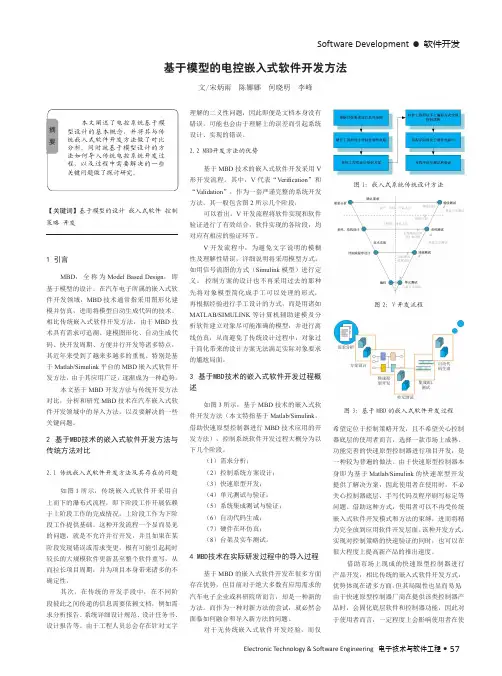
Software Development •软件开发Electronic Technology & Software Engineering 电子技术与软件工程• 57【关键词】基于模型的设计 嵌入式软件 控制策略 开发1 引言MBD ,全称为Model Based Design ,即基于模型的设计。
在汽车电子所属的嵌入式软件开发领域,MBD 技术通常指采用图形化建模并仿真,进而将模型自动生成代码的技术。
相比传统嵌入式软件开发方法,由于MBD 技术具有需求可追溯、建模图形化、自动生成代码、快开发周期、方便并行开发等诸多特点,其近年来受到了越来多越多的重视。
特别是基于Matlab/Simulink 平台的MBD 嵌入式软件开发方法,由于其应用广泛,逐渐成为一种趋势。
本文基于MBD 开发方法与传统开发方法对比,分析和研究MBD 技术在汽车嵌入式软件开发领域中的导入方法,以及要解决的一些关键问题。
2 基于MBD技术的嵌入式软件开发方法与传统方法对比2.1 传统嵌入式软件开发方法及其存在的问题如图1所示,传统嵌入式软件开采用自上而下的瀑布式流程,即下阶段工作开展依赖于上阶段工作的完成情况,上阶段工作为下阶段工作提供基础。
这种开发流程一个显而易见的问题,就是不允许并行开发,并且如果在某阶段发现错误或需求变更,极有可能引起耗时较长的大规模软件更新甚至整个软件重写,从而拉长项目周期,并为项目本身带来诸多的不确定性。
其次,在传统的开发手段中,在不同阶段彼此之间传递的信息需要依赖文档,例如需求分析报告、系统详细设计规范、设计任务书、设计报告等。
由于工程人员总会存在针对文字基于模型的电控嵌入式软件开发方法文/宋炳雨 陈娜娜 何晓明 李峰理解的二义性问题,因此即便是文档本身没有错误,可能也会由于理解上的误差而引起系统设计、实现的错误。
2.2 MBD开发方法的优势基于MBD 技术的嵌入式软件开发采用V 形开发流程。
mbd测试验证流程下载温馨提示:该文档是我店铺精心编制而成,希望大家下载以后,能够帮助大家解决实际的问题。
文档下载后可定制随意修改,请根据实际需要进行相应的调整和使用,谢谢!并且,本店铺为大家提供各种各样类型的实用资料,如教育随笔、日记赏析、句子摘抄、古诗大全、经典美文、话题作文、工作总结、词语解析、文案摘录、其他资料等等,如想了解不同资料格式和写法,敬请关注!Download tips: This document is carefully compiled by theeditor. I hope that after you download them,they can help yousolve practical problems. The document can be customized andmodified after downloading,please adjust and use it according toactual needs, thank you!In addition, our shop provides you with various types ofpractical materials,such as educational essays, diaryappreciation,sentence excerpts,ancient poems,classic articles,topic composition,work summary,word parsing,copy excerpts,other materials and so on,want to know different data formats andwriting methods,please pay attention!MBD(Model-Based Design,基于模型的设计)测试验证流程是一种基于模型的软件开发方法,它将系统设计和测试验证紧密结合,通过对模型的验证和测试来确保系统的正确性和可靠性。
2008-01-0085Model-Based Design for Hybrid Electric Vehicle SystemsSaurabh Mahapatra, Tom Egel, Raahul Hassan, Rohit Shenoy, Michael Carone Copyright © 2008 The MathWorks, Inc.ABSTRACTIn this paper, we show how Model-Based Design can be applied in the development of a hybrid electric vehicle system. The paper explains how Model-Based Design begins with defining the design requirements that can be traced throughout the development process. This leads to the development of component models of the physical system, such as the power distribution system and mechanical driveline. We also show the development of an energy management strategy for several modes of operation including the full electric, hybrid, and combustion engine modes. Finally, we show how an integrated environment facilitates the combination of various subsystems and enables engineers to verify that overall performance meets the desired requirements. 1. INTRODUCTIONIn recent years, research in hybrid electric vehicle (HEV) development has focused on various aspects of design, such as component architecture, engine efficiency, reduced fuel emissions, materials for lighter components, power electronics, efficient motors, and high-power density batteries. Increasing fuel economy and minimizing the harmful effects of the automobile on the environment have been the primary motivations driving innovation in these areas.Governmental regulation around the world has become more stringent, requiring lower emissions for automobiles (particularly U.S. EPA Tier 2 Bin 5, followed by Euro 5). Engineers now must create designs that meet those requirements without incurring significant increases in cost. According to the 2007 SAE’s DuPont Engineering survey, automotive engineers feel that cost reduction and fuel efficiency pressures dominate their work life [1] and will continue to play an important role in their future development work.In this paper, we explore key aspects of hybrid electric vehicle design and outline how Model-Based Design can offer an efficient solution to some of the key issues. Due to the limited scope of the paper, we do not expect to solve the problem in totality or offer an optimal design solution. Instead, we offer examples that will illustrateThe MathWorks, Inc.the potential benefits of using Model-Based Design in the engineering workflow. Traditionally, Model-Based Design has been used primarily for controller development.One of the goals of this paper is to show how Model-Based Design can be used throughout the entire system design process.In section 2, we offer a short primer on HEVs and the various aspects of the design. Section 3 is devoted to Model-Based Design and the applicability of the approach to HEV development. Sections 4, 5, and 6 will focus on examples of using Model-Based Design in a typical HEV design.2. HYBRID ELECTRIC VEHICLE DESIGNCONCEPTA block diagram of one possible hybrid electric vehicle architecture is shown in Figure1. The arrows represent possible power flows. Designs can also include a generator that is placed between the power splitter and the battery allowing excess energy to flow back into thebattery.Figure 1: The main components of a hybrid electric vehicle.Conceptually, the hybrid electric vehicle has characteristics of both the electric vehicle and the ICE (Internal Combustion Engine) vehicle. At low speeds, it operates as an electric vehicle with the battery supplying the drive power. At higher speeds, the engine and the battery work together to meet the drive power demand. The sharing and the distribution of power between thesetwo sources are key determinants of fuel efficiency. Note that there are many other possible designs given the many ways that power sources can work together to meet total demand.DESIGN CONSIDERATIONSThe key issues in HEV design [2] are typical of classical engineering problems that involve multilayer, multidomain complexity with tradeoffs. Here, we discuss briefly the key aspects of the component design: very similar to those of a traditional ICE. Engines used in an HEV are typically smaller than that of a conventional vehicle of the same size and the size selected will depend on the total power needs of the vehicle.design are capacity, discharge characteristics and safety. Traditionally, a higher capacity is associated with increase in size and weight. Discharge characteristics determine the dynamic response of electrical components to extract or supply energy to the battery. motors, AC induction motors, or Permanent Magnet Synchronous Motors (PMSM). Each motor has advantages and disadvantages that determine its suitability for a particular application. In this list, the PMSM has the highest power density and the DC motor has the lowest. [3].splitter that allows power flows from the two power sources to the driveshaft. The engine is typically connected to the sun gear while the motor is connected to the ring gear.aerodynamic drag interactions with weight and gradability factors accounted for in the equations.process of the hybrid powertrain is to study the maximum torque demand of the vehicle as a function of the vehicle speed. A typical graph is shown in Figure 2. Ratings of the motor and the engine are determined iteratively to satisfy performance criteria and constraints. The acceleration capabilities are determined by the peak power output of the motor while the engine delivers the power for cruising at rated velocity, assuming that the battery energy is limited. Power sources are coupled to supply power by the power-splitter, and the gear ratio of the power-splitter is determined in tandem. The next steps include developing efficient management strategies for these power sources to optimize fuel economy and designing the controllers. The final steps focus on optimizing the performance of this system under a variety of operating conditions.Figure 2: Maximum torque demand as a function of vehicle tire speed.3. MODEL-BASED DESIGN OF AN HEVMOTIVATIONIn this section, we outline some of the challenges associated with HEV design and explain the motivation for using Model-Based Design as a viable approach for solving this problem.of an HEV design problem is reflected in the large number of variables involved and the complex nonlinear relationships between them. Analytical solutions to this problem require advanced modeling capabilities and robust computational methods.set of requirements to meet the vehicle performance and functionality goals. Requirements refinement proceeds iteratively and depends on implementation costs and equipment availability.conceptualize the operation of the system’s various components and understand the complex interactions between them. This often requires experimentation with various system topologies. For example, studies may include comparing a series configuration with a parallel configuration. Because the goal is a better understanding of the overallsystem behavior, the models must include the appropriate level of detail. system level to a more detailed implementation, engineers elaborate the subsystem models to realize the complete detailed system model. This can be accomplished by replacing each initial model of a component with the detailed model and observing the effects on performance. Completing this process andrealizing a detailed model of the system requires robust algorithms for solving complex mathematics in a timely fashion.and mechanical components. Typically these components are designed by domain specialists. To speed development, these engineers need to effectively communicate and exchange design ideas with a minimum of ambiguity.typical HEV design is to increase the fuel efficiency of the vehicle while maintaining performance demands. Intuitively, one can look at this problem as finding the optimal use of the power sources as a function of the vehicle internal states, inputs, and outputs satisfying various constraints. This translates to the requirement for switching between various operational “power modes” of the vehicle as a func tion of the states, inputs, and measured outputs [4]. In a true environment for Model-Based Design the power management algorithms co-exist with the physical system models.complexity of the various subsystems, HEV controller design is typically a complex task. A variety of control algorithms specific to each subsystem may be required. For example, the controller that manages the frequency of the input voltage to the synchronous motor will be different from the simple control used for torque control of the same motor. Typically, this will manifest itself as a multistage, multiloop control problem. Successful implementation of the controllers requires deployment of these algorithms on processors that are integrated while interfacing with the physical plant. testing ensures that it continues to meet requirements. Detection of errors early in the process helps reduce costs associated with faulty designs. As design errors trickle down the various workflow stages the costs associated with correcting them increase rapidly[5]. The ability to continually verify and validate that requirements are being satisfied isa key aspect of Model-Based Design.A software development environment for Model-Based Design must be able to address the aforementioned challenges. Additionally, a single integrated environment facilitates model sharing between team members. The ability to create models at various levels of abstraction is needed to optimize the simulation time. A mechanism for accelerating the simulation as the complexity increases will also be important. PROCESS OF MODEL-BASED DESIGNModel-Based Design can be thought of as a process of continually elaborating simulation models in order to verify the system performance. The overall goal is to ensure first pass success when building the physicalprototype. Figure 3 shows the key elements of Model-Based Design.The system model forms the “executable specification” that is used to communicate the desired system performance. This model is handed over to the various specialists who use simulation to design and further elaborate the subsystem models. These specialists refine the requirements further by adding details or modifying them. The detailed models are then integrated back into the system level realization piece by piece and verified through simulation. This goes on iteratively until a convergence to an optimal design that best meets the requirements results. During Model-Based Design, C-code generation becomes an essential tool for verifying the system model. The control algorithm model can be automatically converted to code and quickly deployed to the target processor for immediate testing. Code can also be generated for the physical system to accelerate the simulation and/or to test the controller with Hardwarein the Loop simulation.Figure 3: The key elements of Model-Based Design.4. SYSTEM LEVEL MODELING OF AN HEVIn the first stage of the HEV design, the system-level description of the system is realized. Experimentation enables the system designer to explore innovative solutions in the design space resulting in optimal architectures. Our approach has been inspired by an earlier SAE paper [6]. REQUIREMENTSIn the initial stages of the project, it is not uncommon for the specifications of subsystem components to shift. The requirements are in a preliminary form, and are based on previous designs, if available, or best engineering judgment. Requirements are refined when each of the component models is delivered to component designers for additional refinement. There are, however, certain requirements that the system architect understands fully, and can lock down. As the project moves from requirements gathering to specification, the concepts of the system architects can be included in the model. Collaboration between architects and designers leads to a much better and more complete specification. The system can be expressed as a series of separate models that are to be aggregated into an overall system model for testing. Breaking down the model into components facilitates component-based development and allows several teams to work on individual components in parallel. This kind of concurrent development was facilitated by the parallel configuration we chose for our example, in which the electrical and mechanical power sources supply power in parallel. The broad design goals were:Improve fuel efficiency to consume less than 6.5liters per 100 km (L/100 km) for the driver input profile shown in Figure 4.Cover a quarter mile in 25 seconds from rest. Attain a top speed of 193 kph.Figure 4: Driver input profile as outlined in the requirements document.These and other such requirements are typically captured in a requirements document that engineers can associate with the design models. This provides the ability to trace the requirements throughout the model, a key component of Model-Based Design. VEHICLE DYNAMICSModeling the vehicle dynamics can be a challenging task. When creating any simulation model it is important to consider only the effects that are needed to solve the problem at hand. Superfluous details in a model will only slow down the simulation while providing little or noadditional benefit. Because we are primarily interested in the drive cycle performance, we will limit our vehicle model to longitudinal dynamics only. For example, the vehicle was initially modeled as a simple inertial load on a rotating shaft connected to the drive train. ENGINEA complete engine model with a full combustion cycle is also too detailed for this application. Instead, we need a simpler model that provides the torque output for a given throttle command. Using Simulink® and SimDriveLine™, we modeled a 57kW engine with maximum power delivery at 523 radians per second, as shown in Figure5.Figure 5: Engine modeled using blocks from the SimDriveline™ library. SYNCHRONOUS MOTOR/GENERATORThe synchronous motor and generator present an interesting example of electromechanical system modeling. Standard techniques for modeling synchronous machines typically require complex analysis of equations involving electrical and mechanical domains. Because the input source to this machine drive is a DC battery and the output is AC, this would require the creation of complex machine drive and controller designs – often a significant challenge at this stage.An averaged model that mathematically relates the control voltage input with the output torque and resulting speed is a useful alternative. This simplification allows us to focus on the overall behavior of this subsystem without having to worry about the inner workings. Furthermore, we can eliminate the machine drive by simply feeding the DC voltage directly to this subsystem. With this averaged model, we only need a simple Proportional-Integral (PI) controller to ensure effective torque control. TheMotor/Generator subsystem design will be explored in more detail in the next section. POWER-SPLITTERThe power-splitter component is modeled as a simple planetary gear, as shown in Figure 6. With these building blocks, more complex gear topologies can easily be constructed and tested within the overall system model.Figure 6: Power-splitter modeled as a planetary gear with connections.POWER MANAGEMENTThe power management subsystem plays a critical role in fuel efficiency.The subsystem has three main components:• Mode logic that manages the various operatingmodes of the vehicle.• An energy computation block that computes theenergy required to be delivered by the engine, the motor, or both in response to gas pedal input at any given speed.• An engine controller that ensures the engine is theprimary source of power and provides most of the torque. The motor and generator controllers provide torque and speed control.MODE LOGICFor efficient power management, an understanding of the economics of managing the power flow in the system is required. For example, during deceleration, the kinetic energy of the wheels can be partially converted to electrical energy and stored in the batteries. This implies that the system must be able to operate in different modes to allow the most efficient use of the power sources.We used the conceptual framework shown in Figure 7 to visualize the various power management modes.Algorithm design starts with a broad understanding of the various possible operating modes of the system. In our example, we identified four modes—low speed/start, acceleration, cruising, and braking modes. For each of these modes, we determined which of the power sources should be on and which should be off.The conceptual framework of the mode logic is easily implemented as statechart. Statecharts enable the algorithm designer to communicate the logic in an intuitive, readable form.Figure 7: Mode logic conceptualized for the hybrid vehicle.The Stateflow® chart shown in Figure 8 is a realization of the conceptual framework shown in Figure 7. While very similar to the conceptual framework, the Stateflow chart has two notable differences. The “acceleration” and “cruise” states have been grouped to form the “normal” superstate, and the “low speed/start” and “normal” states have been grouped together to form the “motion” superstate. This grou ping helps organize the mode logic into a hierarchical structure that is simpler to visualize and debug.Figure 8: Mode logic modeled with Stateflow®. SYSTEM REALIZATIONAfter the HEV components have been designed, they can be assembled to form the parallel hybrid system shown in Figure9.Figure 9: System-level model of the parallel HEV.This system model can then be simulated to determine if the vehicle meets the desired performance criteria over different drive cycles. As an example, for the input to the system shown in Figure 4, the corresponding speed and the liters per 100 km (L/100 km) outputs are shown in Figure 10. Once the baseline system performance has been evaluated using the system model, we begin the process of model elaboration. In this process, we add more details to the subsystems models to make them more closely represent the actual implementation. During this process, design alternatives can be explored and decisions made based on the analysis results. This is a highly iterative process that is accelerated using Model-Based Design.5. MODEL ELABORATIONIn the model elaboration stage, the subsystem components undergo elaboration in parallel with requirements refinement.A subsystem block is an executable specification because it can be used to verify that the detailed model meets the original set of requirements.As an example, we show how the generator machine drive undergoes requirements refinement and model elaboration. We assume that the engineer responsible for themachine drive design will carry out the model elaboration of the plant and the associated controller.REQUIREMENTS REFINEMENTThe machine drive is an aggregated model of the machine and the power electronics drive. In the system level modeling phase, the key specification is the torque-speed relationship and the power loss. This information was sufficient to define an abstract model to meet the high-level conceptual requirements.Figure 10: Output speed and L/100 km metric for the averaged model.As additional design details are specified, the model must become more detailed to satisfy the subsystem requirements. For example, the generator model will need parameters such as the machine circuit equivalent values for resistance and inductance. Engineers can use this specification as the starting point towards the construction of an electric machine customized for this HEV application.In the case of the generator drive, as the machine model is elaborated from an averaged model to a full three phase synchronous machine implementation, the controller must also be elaborated. PLANT ELABORATIONThe machine model for the synchronous generator is elaborated using SimPowerSystems™ blocks that represent detailed models of power system components and drives. For this model, the electrical and mechanical parts of the machine are each represented by a second-order state-space model. Additionally, the internal flux distribution can be either sinusoidal or trapezoidal. This level of modeling detail is needed to make design decisions as the elaboration process progresses.Figure 11: Detailed PMSM model parameters.The details of this model are captured in the model parameters shown in Figure 11, which specify the effects of internal electrical and magnetic structures.CONTROL ELABORATIONThe controller used in the averaged model of the AC machine drive is a simple PI controller. In model elaboration of the synchronous machine plant, a DC battery source supplies energy to the AC synchronous machine via an inverter circuit that converts DC to AC. These changes in plant model structure and detail require appropriate changes to the controller model to handle different control inputs and implement a new strategy. For example, the power flow to the synchronous machine is controlled by the switching control of the three phase inverter circuit. This added complexity was not present in the initial model of the machine drive because we focused on its behavior rather than its structure. We implemented a sophisticated control strategy, shown in Figure 12, that included cascaded speed and vector controllers [7]. The controllers were developed using Simulink® Control Design™ to satisfy stability and performance requirements.VERIFICATION AND VALIDATIONAt every step of the model elaboration process, the model is verified and validated. Figure 13 shows the averaged and detailed models as they are tested in parallel.Figure 12: Controller elaboration as we move from averaged (top) to detailed (below) model.The test case is a 110 radians per second step input to the machine. The response, shown in Figure 14, reveals comparable performance of both models. This serves as a visual validation that the detailed model is performing as desired. More elaborate testing schemes and formal methods can be devised with test case generation and error detection using assertion blocks from Simulink® Verification and Validation™ [8].Figure 13: Testing of the averaged and the detailed models for speed control with a 1000 rpm step input.SYSTEM INTEGRATIONAfter the component model elaboration and testing is complete, the subsystem containing the averaged model is replaced with the detailed model and the overall system is simulated again.Figure 14: Comparison between the averaged andthe detailed models of the machine drive. This integration will proceed, one component at a time, until the overall system level model contains all the detailed models for each component. This ensures each component is tested and verified in the system model. A single modeling environment for multidomain modeling facilitates the integration. In our example, we used Simulink for this purpose. In Figure 15, we compare the results of the averaged and the detailed models for the driver input profile shown in Figure 4. The detailed model shows deterioration in the speed and L/100 km performance metrics, which can be attributed to the additional detail incorporated into the model.4. CONTROLLER DEPLOYMENTThe electronic control unit (ECU) layout, deployment, and implementation are challenging problems that require innovative thinking. Typically, this requires exploration of the design space to optimize various criteria.Once the design of the system controllers is complete, ECU layout strategy must be considered. In a typical vehicle, we would likely keep some of the controllers inside a centralized ECU, while distributing the others throughout the car.One potential layout would implement the controller for the synchronous motor on a dedicated floating point microcontroller situated closer to the machine, instead of incorporating the controller as part of the centralized ECU. Such a strategy would allow for faster response times from the motor controller for efficient control. If a mix of centralized and distributed controller architecture is under consideration, then the extra layer of complexity introduced by the communication networkshould be accounted for in the modeling.Figure 15: Speed and L/100 km metric comparisons for averaged and detailed models for the HEV. Cost and performance considerations will drive design decisions regarding the selection of floating point or fixed point implementation of each controller. For example, one may consider implementing the controller for the synchronous generator on a fixed-point processor to lower the cost of the overall architecture.6. SIMULATION PERFORMANCEThe final system-level model of the HEV will contain detailed lower-level models of the various components. As model complexity increases, it will take longer to simulate the model in the software environment. This behavior is expected because the model contains more variables, equations, and added components which incur an additional computational cost. Intuitively, this can be visualized as an inverse relationship between simulation performance and complexity of the model as shown in Figure 16.Running the simulations in a high-performance computing environment can offset the increase in simulation times that comes with increased complexity. . With the advent of faster, multicore processors, it is possible to run large simulations without having to investin supercomputer technology.Figure 16: Simulation performance deteriorates with increasing model complexity. We used Simulink simulation modes that employ code generation technology [9] to accelerate the simulation of our model. The improvements in the simulation performance are shown in Figure 17.Figure 17: Comparison of Simulink® simulation modes for the detailed HEV model.CONCLUSIONIn this paper, we first described a typical HEV design and gave an overview of the key challenges. We discussed how the multidomain complications arise from the complex interaction between various mechanical and electrical components—engine, battery, electric machines, controllers, and vehicle mechanics. This complexity, combined with the large number of subsystem parameters, makes HEV design a formidable engineering problem.We chose Model-Based Design as a viable approach for solving the problem because of its numerous advantages, including the use of a single environment for managing multidomain complexity, the facilitation of iterative modeling, and design elaboration. Continuous validation and verification of requirements throughout the design process reduced errors and development time.Our first step in the development process was the realization of a system-level model of the entire HEV. The subsystem components were averaged models, which underwent model elaboration with requirements refinement and modifications in parallel. We showed how statecharts can be used to visualize the operating modes of the vehicle. After each component model was elaborated, we integrated it into the system-level model, compared simulation results of the averaged and detailed models, and noted the effect of model elaboration on the outputs. When simulation times grew long as we moved towards a fully detailed model, we introduced techniques to alleviate this issue. ACKNOWLEDGMENTSThe authors would like to acknowledge the following fellow MathWorks staff who contributed towards the development of the HEV models used in this paper and the writing of this paper. In alphabetical order—Bill Chou, Craig Buhr, Jason Ghidella, Jeff Wendlandt, Jon Friedman, Rebecca Porter, Rick Hyde, and Steve Miller. REFERENCES1. L. Brooke, “Cost remains the boss”, AutomotiveEngineering International, April 2007, SAE International.2. Iqbal Husain, “Electric and Hybrid Vehicles—DesignFundamentals”, 1st E dition, © 2003 CRC Press.3. S J. Chapman, “Electric Machinery Fundamentals”,4th Edition, © 2004 McGraw-Hill Inc.4. Han, Zhang, Yuan, Zhu, Guangyu, Tian andQuanshi, Chen, “Optimal energy management strategy for hybrid electric vehicles”, SAE Paper 2004-01-0576. 5. P. F. Smith, S. Prabhu, and J. Friedman, “Best。

基于NX软件和MBD技术的圈椅数字化模型构建基于NX软件和MBD技术的圈椅数字化模型构建概述数字化技术的发展使得产品设计与制造的过程更加高效和精确,其中,基于MBD(Model Based Definition,基于模型定义)的数字化建模技术在产品设计中具有重要的作用。
本文将以基于NX软件和MBD技术的圈椅数字化模型构建为例,介绍该技术在产品设计和制造中的应用。
一、MBD技术简介MBD技术是一种基于三维数字化模型的设计方法,它将产品的几何、尺寸、材料、工艺等信息嵌入到数字化模型中,实现了从纸质图纸到数字化设计的转变。
MBD技术的主要特点包括:减少了纸质图纸的使用,提高了设计效率;准确性高,避免了因传统图纸解读不明确而产生的错误;便于产品设计和制造的数字化协同。
二、圈椅数字化模型构建的需求座椅作为常见的产品之一,在设计和制造过程中也面临着一系列的问题。
传统的座椅设计需要依靠纸质图纸,设计师需要通过手绘图纸来表达他们的设计意图,这不仅浪费时间和资源,还容易出现误差。
此外,座椅模型设计过程中的信息传递不畅也是一个问题。
因此,基于NX软件和MBD技术的数字化模型构建成为解决这些问题的有效方法。
三、基于NX软件的数字化模型构建NX软件是一种功能强大的CAD(Computer-Aided Design,计算机辅助设计)软件,提供了丰富的工具和功能,可用于实现数字化模型的构建。
在圈椅数字化模型构建过程中,可以通过以下步骤来进行:1.模型建立:在NX软件中,设计师可以通过绘制几何实体、创建曲面等功能来建立座椅的数字化模型。
在这一步骤中,需要根据设计要求和产品功能进行模型的构建,在尺寸、形状、曲面等方面进行精确的设计。
2.参数化设计:NX软件提供了参数化设计功能,设计师可以通过设定参数来控制数字化模型的形状和尺寸,实现设计的灵活性和可编辑性。
通过参数化设计,可以方便地进行编辑和修改,提高了设计效率。
3.材料和工艺信息嵌入:MBD技术的核心是将产品的材料和工艺等信息嵌入到数字化模型中。
带你了解Model based testing(MBT)基于模型的测试Bad programmers worry about the code.Good programmers worry about data structures and their relationships.在Agile Testing领域比较知名的一位专家Elisabeth Hendrickson 也从测试的角度对数据的重要性做过一些阐述,她列举了常见的测试设计技术:Test Design Technique等价类边界值Data Type AttacksCRUDDifferent configurationsCount (user count, resource count)然后做出了归纳,Its all about the variables.所以我们可以看到,如果能建立系统的数据模型,无论对于(开发)和测试都是很有帮助的。
以计算机行业常见的和磁盘相关的测试,来说明如何用数据模型对测试(需求)建模:然后我们把它翻译成框架可以识别的格式,用了一些非常简单的python语法来描述。
然后可以通过框架生成自动化用例:另外一种常见的模型是状态机模型,主要是针对用户的行为建模:比如Bug管理系统的工作流模型或者SIP 协议的呼叫模型:SIP协议呼叫相关的测试:首先我们还是把它描述成框架可以识别的格式:我们看到,可能的测试路径是很多的,那怎么才可以以最小的测试代价达到我们的覆盖率的目标呢?假设我们的覆盖率目标定义成以最小的成本覆盖所有状态之间的迁移,那我们面临的其实是一个数学问题,那就是在一个有向图上,如何找到最短的路径覆盖。
这其实是一个著名图论问题。
邮递员从邮局出发送信,要求对辖区内每条街,都至少通过一次,再回邮局。
在此条件下,怎样选择一条最短路线?此问题由中国数学家管梅谷于1960年首先研究并给出算法,故名。
通过邮递员算法,我们看到我们一共需要28个步骤才能覆盖所有图中的变化:然后我们也可以把它变成可执行的Robot Case。
汇报人:日期:contents •MBD技术概述•MBD技术的关键技术•MBD技术的发展趋势•MBD技术的挑战与解决方案•MBD技术的实际应用案例•MBD技术的未来展望目录MBD技术概述01•MBD技术的定义:MBD(Model-Based Design)技术是一种基于模型的设计方法,它使用计算机模型来描述产品、过程和系统的行为和性能。
MBD技术广泛应用于航空、汽车、船舶、电子、工业设备等领域,是一种现代化的设计方法。
MBD技术的定义•MBD技术的应用范围:MBD技术被广泛应用于各种领域,如航空航天、汽车、船舶、电子设备、工业设备等。
它可以帮助设计师在早期阶段发现和解决潜在的设计问题,提高设计的可靠性和效率。
MBD技术的应用范围•MBD技术的发展历程:MBD技术自20世纪90年代初期开始发展,最初主要用于机械工程领域。
随着计算机技术和数值模拟技术的发展,MBD技术的应用范围逐渐扩大,涉及更多的领域和复杂的设计问题。
如今,MBD技术已经成为一种成熟的设计方法,被广泛应用于各种行业。
MBD技术的发展历程MBD技术的概念开始出现,最初主要用于机械工程领域。
20世纪90年代初期随着计算机技术和数值模拟技术的发展,MBD技术的应用范围逐渐扩大,涉及更多的领域和复杂的设计问题。
20世纪90年代中期MBD技术逐渐成熟,成为一种广泛使用的现代化设计方法。
21世纪初随着数字化设计和智能制造的快速发展,MBD技术的应用前景更加广阔,被广泛应用于各种行业。
近年来MBD技术的关键技02术基于物理原理和实际数据建立模型,涵盖系统各个组成部分及其相互关系。
模型建立模型验证模型确认通过实验和实际运行数据验证模型的准确性和可靠性。
确认模型是否能够正确地描述和预测系统的行为。
030201采用各种优化算法,如梯度下降法、遗传算法等,寻找最优解。
优化算法基于模型的控制算法能够实现高效、稳定、鲁棒的控制。
控制算法通过实时数据反馈,实现实时调整和优化控制策略。
mbd技术概念MBD技术概念MBD(Model-Based Design)技术是一种基于模型的设计方法,它将系统的设计、开发和验证过程建立在数学模型之上。
该技术是一种全新的软件开发方法,它能够使开发人员更加高效地进行系统设计和开发。
一、MBD技术的背景1.1 传统软件开发方法的问题传统软件开发方法主要是基于文档编写的方式,这种方式存在以下问题:(1)文档编写需要大量时间和精力,而且容易出现错误。
(2)文档编写不利于代码重用和维护。
(3)文档编写无法满足对系统性能、可靠性等方面的要求。
1.2 MBD技术的优势与传统软件开发方法相比,MBD技术具有以下优势:(1)基于模型的设计可以更加直观地描述系统结构和行为。
(2)模型可以自动生成代码,提高代码质量和效率。
(3)模型可以方便地进行验证和测试,并且可以提前检测出潜在问题。
二、MBD技术的基本原理2.1 模型驱动设计MBD技术采用模型驱动设计(MDD)思想,即以模型为中心进行系统设计和开发。
在MDD中,模型是系统的核心,所有的设计、开发和测试都是基于模型进行的。
2.2 模型的构建MBD技术中的模型通常是基于数学模型构建的,包括状态机、数据流图、控制流图等。
这些模型可以直观地描述系统结构和行为,并且可以方便地进行验证和测试。
2.3 模型自动生成代码在MBD技术中,模型可以自动生成代码,这样可以提高代码质量和效率。
同时,代码生成器还可以根据不同平台生成相应的代码,使得软件能够在不同平台上运行。
三、MBD技术的应用领域MBD技术已经广泛应用于各个领域,包括航空航天、汽车制造、电子设备等。
下面分别介绍一下这些领域中MBD技术的应用情况。
3.1 航空航天在航空航天领域,MBD技术主要用于飞行控制系统和导航系统等方面。
通过采用MBD技术,可以更加准确地描述飞行器的动态特性,并且能够提高飞行器的安全性能。
3.2 汽车制造在汽车制造领域,MBD技术主要用于汽车控制系统和发动机控制系统等方面。
什么叫基于模型的设计?为什么要基于模型的设计?基于模型的设计过程中,需要做什么事情?再问几个小问题:模型验证是否必要?模型验证有哪些工作可以做?模型验证是否一定需要被控对象模型?代码生成效率如何?底层驱动是否要建模?Embedded Coder(以前的RTW Embedded Coder)支持哪些芯片?MIL、SIL、PIL、HIL的目的和实现方式?如何定点化?如何做代码集成?什么叫基于模型的设计?这是一个很大的话题,因为本人能力所限,仅讨论使用Simulink模型开发嵌入式软件的设计过程。
也就是说,我只能聊基于模型的嵌入式软件设计。
我的理解是,通过对算法建模进行软件设计的过程,都可以叫基于模型的设计。
当然,如果仅限于算法建模,把Simulink/Stateflow当做Visio使用,而不去进行其他环节的工作,这样的基于模型设计是不完整的,可能对你的开发效率不会有很大的提升。
如果想通过基于模型的设计提升软件开发团队的开发效率,提高软件品质,我觉得至少有如下几点可以考虑:算法建模算法模型的验证文档自动化代码生成代码和模型的等效性验证。
传统的开发过程中,我们有一个环节,需求捕获,也即,从系统需求分解出软件需求。
在基于模型的设计过程中,我们同样可以通过分析系统需求,获得软件需求。
当然,根据系统需求的详细程度,我们可以考虑是否要写专门的软件需求。
在基于模型的软件设计中,我们主要关心的是系统的功能需求,或者说可以通过软件实现的功能需求。
如果这部分需求在系统需求文档里已经有非常清楚的定义,那么我们可以以系统需求文档作为依据建立模型。
当然,如果系统需求不是足够清楚,那我们有必要编写专门的软件需求文档。
如果不考虑Simulink/Stateflow的应用上的问题,也就是说,如果我们都是熟练的Simulink/Stateflow用户,那么建模过程的主要工作是需求分析,通俗点讲,需求弄清楚了,建模也就是非常简单的事情了。
基于模型设计在机电系统开发中的应用作者:王海滨闫鹏程武涛欧栋杰来源:《硅谷》2014年第05期摘要随着现代控制技术的发展,控制算法越来越复杂,控制算法的自动验证和代码自动生成已经成为趋势。
传统的电机控制算法开发是系统仿真,编写代码,最后测试。
采用传统手工编程的方式去编写复杂的控制算法,对于初学者来说难度非常大。
对于算法设计人员来说,需要一种方法能够解决以上问题。
关键词基于模型的设计;Embedded Coder;磁场定向算法;永磁同步电机;PIL中图分类号:TP309 文献标识码:A 文章编号:1671-7597(2014)05-0053-01Matlab提供的基于模型设计平台(Model Based Design,MBD),可以实现从需求分析到代码验证的整个开发过程,用户可以建立系统级模型的仿真验证,优化系统参数,自动生成高效的目标器件专用代码。
利用Matlab提供的开发环境,用户可以开发和验证控制算法,成功的完成从算法的设计验证到自动生成代码过程。
1 电机控制系统开发流程在开发中,首先是通过文本需求建立可执行文档,在这一部分中,主要是建模,通过建模可以避免传统文本的弊端,通过可视化和可执行化的模型避免文本需求的歧义和冗余。
建模之后,为生成符合相关安全标准的代码,需要对模型进行建模规范检查,使用Simulink V&V工具集可自动完成这一流程。
为验证算法的正确性,模型检查通过后,Matlab提供的System Test(系统测试)与Simulink DesignVerifier(设计验证器)工具可以完成对控制系统的测试。
模型测试后,使用Embedded coder工具生成嵌入式代码,通过编译连接生成目标代码,下载到处理器中做代码的等效性测试,如处理器在环测试(PIL)等。
通过这完整的流程,从文本需求到系统测试提供了一个统一的平台,方便开发人员交流,极大的提高了开发的效率。
2 建模规范检查与测试模型出来并且可以编译之后,首先要做建模标准检查,这个过程使用工具Simulink Verification&Validation工具集提供的model advisor自动化的完成。
什么叫基于模型的设计?为什么要基于模型的设计?基于模型的设计过程中,需要做什么事情?再问几个小问题:模型验证是否必要?模型验证有哪些工作可以做?模型验证是否一定需要被控对象模型?代码生成效率如何?底层驱动是否要建模?Embedded Coder(以前的RTW Embedded Coder)支持哪些芯片?MIL、SIL、PIL、HIL的目的和实现方式?如何定点化?如何做代码集成?什么叫基于模型的设计?这是一个很大的话题,因为本人能力所限,仅讨论使用Simulink模型开发嵌入式软件的设计过程。
也就是说,我只能聊基于模型的嵌入式软件设计。
我的理解是,通过对算法建模进行软件设计的过程,都可以叫基于模型的设计。
当然,如果仅限于算法建模,把Simulink/Stateflow当做Visio使用,而不去进行其他环节的工作,这样的基于模型设计是不完整的,可能对你的开发效率不会有很大的提升。
如果想通过基于模型的设计提升软件开发团队的开发效率,提高软件品质,我觉得至少有如下几点可以考虑:算法建模算法模型的验证文档自动化代码生成代码和模型的等效性验证。
传统的开发过程中,我们有一个环节,需求捕获,也即,从系统需求分解出软件需求。
在基于模型的设计过程中,我们同样可以通过分析系统需求,获得软件需求。
当然,根据系统需求的详细程度,我们可以考虑是否要写专门的软件需求。
在基于模型的软件设计中,我们主要关心的是系统的功能需求,或者说可以通过软件实现的功能需求。
如果这部分需求在系统需求文档里已经有非常清楚的定义,那么我们可以以系统需求文档作为依据建立模型。
当然,如果系统需求不是足够清楚,那我们有必要编写专门的软件需求文档。
如果不考虑Simulink/Stateflow的应用上的问题,也就是说,如果我们都是熟练的Simulink/Stateflow用户,那么建模过程的主要工作是需求分析,通俗点讲,需求弄清楚了,建模也就是非常简单的事情了。
当然,建模的时候,要考虑未来的验证、实现以及后期维护的问题。
我个人的体会,这个阶段,不要着急建模,一定要先弄清需求,另外,建模的时候,模型架构非常重要。
有了模型之后,接下来要做什么事情?代码生成?这是很多比较初级的用户容易犯的错误,犯这个错误的用户,很大程度上是因为没有弄清楚为什么要做基于模型的设计?为什么要做基于模型的设计?我相信很多用户没有仔细考虑这个问题,很多用户做基于模型的设计的理由是:国外的公司都这么做,同行其他公司都这么做......弄清为什么要基于模型的设计,也就是要弄清楚基于模型的设计到底可以给我们带来哪些好处?很多人会非常自然的想到,代码生成,代码生成可以提高软件开发效率。
没错,代码生成是一个很大的好处,但,代码生成不是唯一的,也不是最大的好处。
最大的好处是,算法的早期验证,之前NASA有研究表明,开发初期引入的bug,如果到了晚期才发现出来,那么修复这一的bug,会产生非常大的费用。
所以,我们期望能够尽早的发现开发过程中引入的bug。
如何尽早的发现设计上的错误?传统的开发模式里,我们使用review的方式去发现错误,在质量体系ISO9001里面有定义,任何一份设计,都必须要评审。
评审的目的,也就是为了发现这个阶段的错误,以防错误被带到后续的开发过程中。
而评审的效率,却是非常低下的。
我想凡是参加评审的网友都会有体会。
比如,我在做完一份设计之后,我会邀请我的同事来评审我的工作,而参加评审的这些同事,往往不能有足够的时间了解我的这份工作,而只能在评审会上听我介绍我做的工作,这样的评审,可能会发现一些非常明显的问题,除此之外的,很难发现问题。
评审作为一种非常传统的验证方式,并不能及时发现设计过程中引入的各种错误。
而仿真,从效率上讲,要远高于评审,仿真更容易发现设计中的问题。
仿真是可以运行的,如果我们设定一些输入,运行模型之后,我们会得到相应的输出,我们很容易观测到此时的输出是否是我们期望的输出。
另外还有好处,仿真的结果是确定的,给定输入,就会得到确定的输出,当然,期望输出也是确定的。
而不像评审,同样的文字,对于不同人,可能理解成不同的含义。
代码生成和早期验证之外,基于模型的设计,还可以给我们带来其他好处,比如文档自动化。
我们经常听到这样的说法:我们终于把软件发布出去了,现在可以有时间补文档了...下个月要audit了,所有同事都在补文档....这里我要问:为什么要补文档?补文档,我们可以从中得到两个方面的信息:1.文档很重要,不能没有,至少从质量体系上要求我们必须有文档2.工程师都不愿意写文档,是啊,如果愿意写文档的话,在开发过程中自然会把各类文档写起来的。
好,工程师不愿意写,开发过程中又不能少,如果计算机可以帮我们写,岂不是很美好的事情。
基于模型的设计,可以帮助我们实现文档自动化,至少有相当大的一部分文档可以让计算机替我们写。
其实,基于模型的设计,还有一个天然的优势:图形化设计。
对于工程师来讲,图形化的东西,本身就比文字更容易理解,否则我们在软件开发过程中也不会去画流程图和状态机了。
所以总结一下,基于模型的设计可以从以下方面给我们提供便利:1. 图形化设计2. 早期验证3. 代码生成4. 文档自动化前面我大概论述了为什么要做基于模型的设计,或者说基于模型的设计可以给我们带来哪些好处。
这些好处,最终会大大提高开发效率,并且改善软件品质。
下面,我在说说基于模型的设计里有哪些事情要做,刘博士说的没错,基于模型的设计,自然模型最重要,如何建模,毫无疑问是最为重要的环节。
在软件产品开发中,建模活动里,耗时最多的,就应该是需求分析了,需求分析不仅包括如何正确理解软件需求,而且要考虑如何通过模型实现,真正的画模型的时间,相比之下并不多,如果Simulink/Stateflow用的熟的话,真正打开MATLAB画模型的时间占建模阶段总时间的1/3都不到。
建模之后,接下来就是模型验证,验证,英文单词Verification,英文里面还有另外一个词Validation,确认,很多人不清楚这两个词之间的区别,通俗点讲:Verification是考察你是否正确的做了一件事,而Validation,则是考察你是否做出了正确的东西。
一个强调的是过程,一个在乎的是结果。
闲话少说,咱们继续回到模型验证上来,通常模型验证包含如下活动:建模标准的检查、评审、单元测试、快速原型。
(如果说的不完善,欢迎大家补充)建模标准的检查,可以通过模型检查工具自动完成,建模标准检查的意义,和传统开发模式里C编码标准的意义一致,这里不展开了。
有关评审和单元测试,再专门开贴说吧。
模型验证之后,接下来就可以做代码生成了,有关代码生成,也专门讨论吧。
代码生成之后,需要做代码验证,基于模型的开发过程里面,SIL、PIL都是常用的代码验证方式。
在代码做完SIL或者PIL测试之后,要考虑软件集成了,即应用层软件,也就是通过Simulink 模型生成的软件,和底层驱动软件之间的集成。
软件集成之后,后面的事情,基本上和传统的开发模式差不多了,当然,相对于传统的开发模式,你可以多一个HIL环节出来,不过话又说回来,即便是传统的开发模式,也一样可以有HIL这个环节的。
有关HIL的实现及目的,以后再说。
再说说模型验证的必要性。
我在进入MathWorks之后,接触过很多客户,不少客户在最初引入基于模型设计的时候,根本不在意模型验证工作,他们经常在模型编译通过之后就拿去生成代码,有了代码之后将代码下载到各种快速原型设备上去测试算法,Simulink的仿真功能基本上成了摆设。
并且在这个阶段,不管我如何苦口婆心的给他们介绍模型验证的重要性,在他们那边,却总有各种各样的借口去省略模型验证环节,“项目时间太紧,模型来不及测”,“我们知道规范的开发流程,但是现在人手不够”。
当然,这类用户经常在这样折腾了一段时间之后,还是要回到模型测试上来,他们最终会发现,在HIL设备上测试算法,实在太难,当然,也有坚持的,坚持的结果就是他们所谓的基于模型的设计,开发效率比传统的开发模式高不了多少。
其实,这个问题我们可以这么去看,模型阶段的测试,我们是可以分模块进行的,而HIL上测试,基本上是集成之后的软件。
比如,一个软件有10个模块,在HIL设备上,你很难分离出每个模块的bug,而如果是按模块做单元测试,则就是针对的一个具体的模块。
打一个不算恰当的比方,我们都知道一块2克拉的钻石,价格肯定不是一块1克拉钻石的两倍。
类似的,如果每个软件模块有2个bug,那么你从集成好的软件里去消除这20个bug,耗费的精力肯定不是从每个单元模块里去消除bug所耗精力的总和。
说白了,早期验证是非常重要的,很多软件工程的教材里都有相关的统计数据说明早期验证的重要性,对应到基于模型的开发过程,能在模型级别做的验证,一定不要拖到后续的环节中。
中国有句老话,“心急吃不了热豆腐”,“项目时间紧”或者“人手不够”不能成为我们忽略模型测试的借口。
继续说一下MBD开发过程中都有哪些验证工作要做。
模型出来并且可以编译之后,首先要做建模标准检查,这个过程使用工具(比如MathWorks 公司的Simulink Verification & Validation提供的model advisor)自动化的完成,检查过后,修改模型中不符合公司建模规则的项目。
接下来,就可以进行模型评审了,也就是说,评审的模型有两个前提,一是可以编译的,二是符合公司建模规则的。
这两个前提可以帮助我们消除模型中的一些低级错误,避免在评审过程中有太多的时间花费在这些错误上。
因为评审是建模的工程师和其他同事共同参与的活动,做到上述两个前提,也是对其他同事工作时间的一种尊重。
评审之后,建模的工程师会修改评审中发现的问题,问题多的话,一般会要求修改之后再进行“再评审”,直到在评审中不会发现大量问题。
接下来,我们可以使用Simulink Design Verifier进行模型的结构分析,借助于Simulink Design Verifier自动生成测试用例的功能,去检查结构上是否存在问题,比如是否有不合理的逻辑设计,是否有运行不到的分支等。
再往后,就可以进行模型单元级别的功能测试了。
软件开发过程中,对单元测试的要求是很高的,一般会根据应用的安全性、可靠性要求,给出测试的覆盖率要求。
这个过程中工作量最大的应该是测试用例设计以及测试向量的生成。
测试用例设计,我们一般会根据需求去设计测试用例,当然,也会结合模型结构设计测试用例,这样说来,这里的测试,已经包含了黑盒测试和白盒测试。
有了测试用例,如何把测试用例转换为测试向量,这也是非常重要的环节。
我们知道,在MBD开发过程中,代码都可以自动生成,其他环节,我们要努力做到自动化实现。