SMC系列产品使用说明书
- 格式:doc
- 大小:4.12 MB
- 文档页数:16

Pressure SensorOperation ManualPSE53#/54#/550/56#/57# SeriesThank you for purchasing an SMC PSE53#/54#/550/56#/57# Series Pressure Sensor.Please read this manual carefully before operating the product and make sure you understand its capabilities and limitations.Please keep this manual handy for future reference.To obtain the operation manual about this product, please refer to the SMC website (URL https://) or contact SMC directly.These safety instructions are intended to prevent hazardous situations and/or equipment damage.These instructions indicate the level of potential hazard with the labels of"Caution", "Warning" or "Danger". They are all important notes for safety and must be followed in addition to International standards (ISO/IEC) and other safety regulations.WiringOperatorSafety InstructionsNOTE•The direct current power supply to be used should be UL approved as follows:Circuit (of Class 2) which is of maximum 30 Vrms (42.4 V peak), with UL1310Class 2 power supply unit or UL1585 Class 2 transformer.•The product is a UL approved product only if it has a mark on the body.•Do not drop, hit or apply shock to the Pressure Sensor.•Do not pull the lead wire forcefully, or lift the product by pulling the lead wire.•Do not use in a place where the product could be splashed by oil or chemicals.•Wire correctly.•Do not perform wiring while the power is on.•Do not route wires and cables together with power or high voltage cables.•Be sure to ground terminal FG when using a commercially available switch-mode power supply.•When analogue output is used, install a noise filter (line noise filter, ferrite element, etc.) between the switch-mode power supply and this product.Specifications/Outline with DimensionsRefer to the product catalogue or SMC website (URL https://)for more information about the product specifications and outline dimensions.Note: Specifications are subject to change without prior notice and any obligation on the part of the manufacturer.© 2011-2022 SMC Corporation All Rights Reserved Akihabara UDX 15F, 4-14-1, Sotokanda, Chiyoda-ku, Tokyo 101-0021, JAPAN Phone: +81 3-5207-8249 Fax: +81 3-5298-5362URL https://Attaching the connector to the sensor wire•Strip the sensor wire as shown below.•Do not cut the insulation.•Check that the above preparation has been performed correctly, then part A shown should be pressed in by hand to make temporary connection.•Part A should then be pressed in using a suitable tool, such as pliers.•The e-con connector cannot be re-used once it has been fully crimped.In cases of connection failure such as incorrect order of wires or incomplete insertion, please use a new connector.•When connecting the sensor to the PSE200 or PSE300 series, use connector as listed below.•For information aboutconnectors please consult the manufacturerscatalogue.Controller and applicable sensorsConnecting/Disconnecting•When mounting the connector, insert it straight into the socket, holding thelever and connector body, and push the connector until the lever hooks into the housing, and locks.•When removing the connector, press down the lever to release the hook from the housing and pull the connector straight out.•PSE200A series (PSE5##)•PSE300series (PSE5##)PSE310series (PSE5##-28)•Insert the corresponding wire colour shown in the table into the pin number printed on the sensor connector, to the bottom.•Output specification•PSE5##Voltage output: 1 to 5 VOutput impedance: Approx. 1 kΩ•PSE57#-28Current output: 4 to 20 mAAllowable load impedance: 500 Ω or less (at 24 VDC)100 Ω or less (at 12 VDC)•PSE5#-28Current output: 4 to 20 mAAllowable load impedance: 500 Ω or less (at 24 VDC)100 Ω or less (at 12 VDC)∗: Install the load either on the LINE(+) or LINE(-) side.∗: The PSE53# and PSE54#series are not available with current output.Connecting the sensor cable•Insert the connector into the sensor, paying attention to the connector direction.•The sensor cable includes a connector cover to prevent the connector from falling out.•Install the connector cover to the sensor, rotating clockwise to lock.•To remove the sensor cable, rotate the connector cover anti-clockwise to release the lock, and remove connector cover. After removing the cover, pull out the connector.Piping connections•Cut the tube end perpendicular.•Insert the tubing to the sensor firmly for 8 mm or more from the end of the moulded pipe. The force necessary for piping insertion is approximately 25 N.•Insert the air tube for low pressure to Lo piping and the air tube for high pressure to Hi piping.Air tube (Applicable to I.D. 4)PSE53# seriesPSE550 series PSE54# seriesPSE56# seriesInternal circuit and wiring•When piping, apply a spanner to the piping section of the sensor.•Do not apply unnecessary forces such as twisting, pulling, moment loads, etc.on fittings or tubing.•When a tubing from a company other than SMC is used, ensure that the tubing has an internal diameter and tolerance of ø4±0.3 mm.•Applicable fluid is a fluid that does not corrode SUS316L.•When piping, apply a spanner to the piping section of the sensor.•To protect the sensor from water and dust, install an air tube to a safe area.PS ※※-OMO0006-C•Applicable fluid is a fluid that does not corrode C3604 + nickel plated,AI203 (aluminum oxide) and FKM.•When piping, apply a spanner to the piping section of the sensor.PSE57# series56∗: The pin numbers in the diagram indicate the PSE57#series 4 pin connector.All other series have 3 wires.∗: The pin numbers in the diagram indicate the PSE57#series 4 pin connector.。

Instruction Manual 5 Port Solenoid ValveSeries S0700The intended use of this valve is to control the movement of an actuator.1 Safety InstructionsThese safety instructions are intended to prevent hazardous situationsand/or equipment damage. These instructions indicate the level ofpotential hazard with the labels of “Caution,” “Warning” or “Danger.”They are all important notes for safety and must be followed in additionto International Standards (ISO/IEC) *1), and other safety regulations.*1) ISO 4414: Pneumatic fluid power - General rules relating to systems.ISO 4413: Hydraulic fluid power - General rules relating to systems.IEC 60204-1: Safety of machinery - Electrical equipment of machines.(Part 1: General requirements)ISO 10218-1: Robots and robotic devices - Safety requirements forindustrial robots - Part 1: Robots.•Refer to product catalogue, Operation Manual and HandlingPrecautions for SMC Products for additional information.• Keep this manual in a safe place for future reference.Caution Caution indicates a hazard with a low level of risk which, ifnot avoided, could result in minor or moderate injury.Warning Warning indicates a hazard with a medium level of riskwhich, if not avoided, could result in death or serious injury.Danger Danger indicates a hazard with a high level of risk which, ifnot avoided, will result in death or serious injury.Warning•Always ensure compliance with relevant safety laws andstandards.•All work must be carried out in a safe manner by a qualified person incompliance with applicable national regulations.Caution•The product is provided for use in manufacturing industries only. Donot use in residential premises.2 Specifications2.1 Valve specificationsValve construction Rubber sealFluid AirMaximum operating pressure [MPa] 0.7Minimum operating pressure [MPa] 0.2Ambien and fluid temperature [˚C] Note 1)-10 to 50 (no freezing)Flow rate characteristicsRefer to catalogueResponse timeDuty cycle Contact SMCMinimum operating frequency [Hz] 1 cycle / 30 daysMaximum operating frequency [Hz] 5Pilot valve manual override Push typeLubrication Not requiredImpact/Vibration resistance [m/s2] Note 2)100 / 30Enclosure (based on IEC60529) IP40Mounting orientation UnrestrictedPilot valve exhaustmethod Note 3)Plug lead type Individual exhaustSlim compact bar baseCommon exhaustPlug-in type stacking base2 Specifications - continuedNoise reduction (built-insilencer) [dB] Note 4)Plug-in type 30Plug lead type 20Weight Refer to catalogueTable 1.Note 1) Use dry air to prevent condensation when operating at low temperatures.Note 2) Impact resistance: No malfunction occurred when it is tested with a droptester in the axial direction and at the right angles to the main valve andarmature in both energized and de-energized states every once for eachcondition.Vibration resistance: No malfunction occurred in a one-sweep test between8.3 and 2000 Hz. Test was performed at both energized and deenergizedstates in the axial direction and at the right angles to the main valve andarmature.Note 3) Valves with the external pilot specifications have a pilot EXH with individualexhaust specifications.Note 4) Value may vary depending on pneumatic circuit or pressure.2.2 Solenoid specificationsElectrical entry Grommet (G), M type plug connector (M)Coil rated voltage [VDC] 24, 12Allowable voltage fluctuation ±10% of rated voltageCoil insulation class Class B or equivalentPower consumption [W] (current [mA]) 0.35 (15)Surge voltage suppressor VaristorIndicator light LEDTable 2.2.3 Manifold specifications2.3.1 Plug-in typeModel SS0751-# SS0750-#Manifold type Slim compact bar base Plug-in type stacking basePort size1(P), 3(R) C6, C8, N7, N94(A), 2(B) C2, C3, C4, N1, N3MaximumvalvestationsS kitEX510: 16 stations EX500: 16 stationsEX180: 32 stations EX250/260/600: 24 stationsF kit24 stationsP kitMaximumvalvestationsT kit-20 stationsL kit24 stationsM kitTable 3.2.3.2 Plug lead typeModel SS0752-##C SS0755-#C#C SS0755-#V#CManifold type Body ported Base mountedManifold pitch[mm]7.5 8.5 7.5Portsize1(P),3(R)Rc1/8 M54(A),2(B)C2, C4N1, N3M5, C2, C3, C4N1, N3M3V2, V3, V4Electrical entry C kit C kit S kit (EX510) C kitMaximum valvestations20 20 16 20Table 4.2.4 Pneumatic symbolsRefer to catalogue for pneumatic symbols.2.5 Indicator light2.5.1 Plug-in typeSlim type plug-in manifold Plug-in manifoldFigure 1.2 Specifications - continued2.5.2 Plug lead typeFigure 2.2.6 Special productsWarningSpecial products (-X) might have specifications different from thoseshown in this section. Contact SMC for specific drawings.3 Installation3.1 InstallationWarning•Do not install the product unless the safety instructions have been readand understood.3.2 EnvironmentWarning•Do not use in an environment where corrosive gases, chemicals, saltwater or steam are present.•Do not use in an explosive atmosphere.•Do not expose to direct sunlight. Use a suitable protective cover.•Do not install in a location subject to vibration or impact in excess ofthe product’s specifications.•Do not mount in a location exposed to radiant heat that would result intemperatures in excess of the product’s specifications.3.3 PipingCaution•Before connecting piping make sure to clean up chips, cutting oil, dustetc.•When installing piping or fittings, ensure sealant material does notenter inside the port. When using seal tape, leave 1 thread exposedon the end of the pipe/fitting.•Tighten fittings to the specified tightening torque.Connection threads Proper tightening torque [N∙m]M3 0.4 to 0.5M5 1 to 1.51/8 3 to 5Table 5.3.4 LubricationCaution•SMC products have been lubricated for life at manufacture, and do notrequire lubrication in service.•If a lubricant is used in the system, refer to catalogue for details.3.5 Air supplyWarning•Use clean air. If the compressed air supply includes chemicals,synthetic materials (including organic solvents), salinity, corrosive gasetc., it can lead to damage or malfunction.Caution•Install an air filter upstream of the valve. Select an air filter with afiltration size of 5 μm or smaller.3.6 Manual overrideWarning•Regardless of an electric signal for the valve, the manual override isused for switching the main valve. Since connected equipment willoperate when the manual override is activated, confirm that conditionsare safer prior to activation.•Refer to the catalogue for details of manual override operation.3.7 MountingCaution3 Installation - continued•Ensure gaskets are in good condition, not deformed and are dust anddebris free.•When mounting valves ensure gaskets are present, aligned andsecurely in place and tighten the screws to torque levels as per figuresbelow.•Refer to catalogue for additional information.Plug-in typeValve mounting DIN rail mountingPlug lead typeBody ported Base mountedBody ported (when mounted directlyon wall)-Figure 3.3.8 Electrical circuitsCautionSurge suppression should be specified by using the appropriate partnumber. If a valve type without suppression (Type ‘G’) is used,suppression must be provided by the host controller as close as possibleto the valve.Plug-in and Plug lead (single) Plug-in (double, dual 3-port)Plug lead (double, 3 position, dual 3-port)Figure 4.ORIGINAL INSTRUCTIONSIndicator lightA sideIndicator lightB sideMounting screw (M2)Tightening torque:0.17 N∙m to 0.23 N∙mMounting screw (M2)Tightening torque:0.17 N∙m to 0.23 N∙mM3 threadTightening torque:0.5 N∙m to 1 N∙mMounting screw (M2)Tightening torque:0.17 N∙m to 0.23 N∙mClamping screwTightening torque:0.4 N∙m to 0.6 N∙mSOL.ALEDVaristorA: RedB: GreenIndicator lightA sideIndicator lightB sideSOL.ACOMSOL.BVaristorVaristorSOL.ALEDVaristorSOL.BLEDVaristor3 Installation - continued3.9 Residual voltage of the surge voltage suppressorCaution• The suppressor arrests the back EMF voltage from the coil to a level in proportion to the rated voltage.• Ensure the transient voltage is within the specification of the host controller.• In the case of varistor, the residual voltage is approximately 60 V. 3.10 Countermeasure for surge voltageCaution• At times of sudden interruption of the power supply, the energy stored in a large inductive device may cause non-polar type valves in a de-energized state to switch.• When installing a breaker circuit to isolate the power, consider a valve with polarity (with polarity protection diode), or install a surge absorption diode across the output of the breaker. 3.11 How to attach / detach plug connectorCautionDo not pull the lead wire excessively (with a force of 10 N or more) as the connector and cover might get damaged.Figure 5.3.12 Electrical wiring specifications Caution• The surge voltage created when the power supply is cut off could apply to the de-energized load equipment through the output circuit. In cases where the energized load equipment has a larger capacity (power consumption) and is connected to the same power supply as the product, the surge voltage could malfunction and/or damage the internal circuit element of the product and the internal device of the output equipment. To avoid this situation, place a diode which can suppress the surge voltage between the COM lines of the load equipment and output equipment.• Refer to catalogue for electrical wiring specifications. 3.13 Changing connector entry direction (plug-in type only)CautionRefer to the Specific Product Precautions in the catalogue.Figure 6.3.14 Extended periods of continuous energizationWarningIf a valve will be continuously energized for an extended period of time, the temperature of the valve will increase due to the heat generated by the coil assembly. This will likely adversely affect the performance of the valve and any nearby peripheral equipment.3.15 Effect of back pressure when using a manifoldWarningUse caution when valves are used on a manifold because an actuator may malfunction due to back-pressure.3 Installation - continued3.16 Non- SMC tube brandsCautionWhen using other than SMC brand tube, confirm that the tube outside diameter tolerance is satisfied. Refer to catalogue for additional information.3.17 Connecting tubingRefer to catalogue for additional information.Figure 7.4 How to OrderRefer to catalogue for ‘How to Order’ or to product drawing for special products.5 Outline DimensionsRefer to catalogue for outline dimensions.6 Maintenance6.1 General maintenanceCaution• Not following proper maintenance procedures could cause the product to malfunction and lead to equipment damage.• If handled improperly, compressed air can be dangerous.• Maintenance of pneumatic systems should be performed only by qualified personnel.• Before performing maintenance, turn off the power supply and be sure to cut off the supply pressure. Confirm that the air is released to atmosphere.• After installation and maintenance, apply operating pressure and power to the equipment and perform appropriate functional and leakage tests to make sure the equipment is installed correctly.• If any electrical connections are disturbed during maintenance, ensure they are reconnected correctly and safety checks are carried out as required to ensure continued compliance with applicable national regulations.• Do not make any modification to the product.• Do not disassemble the product, unless required by installation or maintenance instructions. 6.2 Increase manifold stations (Plug-in type only)• Refer to catalogue for details on how to increase connector type manifold stations.Caution• When assembling, tighten the hexagon bolts at the U-side end of the manifold to a recommended torque of 0.85 N ∙m to 0.95 N ∙m. 6.3 Replacement partsRefer to catalogue for details regarding replacement parts such us blanking plate assembly, individual SUP/EXH spacer, individual SUP spacer, individual EXH spacer, SUP block plate, EXH block plate, back pressure check valve, blanking plate with output, port plug, DIN rail mounting bracket, DIN rail, blanking plug, silencer, name plate, dual flow fitting, SUP/EXH block, single and double check blocks.6.3.1 Replacement of one-touch fittingsCaution• Do not apply unnecessary forces such as twisting, pulling, moment loads, vibration and impact, etc. on fittings or tubing. A force of 20 N or more applied to the fitting and/or tube can cause damage to the valve and/or fitting, crushing, bursting, or detachment of tubing, or air leakage.• Refer to catalogue for additional information.6 Maintenance - continuedPlug-in type Plug lead – base mounted typePlug lead – body ported type Figure 8.6.4 Replacement of silencers• Single body ported valve of the plug lead type and the plug-in type has built-in silencers.• Dirty and clogged silencer may reduce cylinder speed or cause a malfunction. Replace the silencer periodically. • Refer to catalogue for additional information. 6.4.1 Plug-in typeFigure 9.6.4.2 Plug lead type (body ported valve)Figure 10.6.5 Pilot valve replacementRefer to catalogue for additional information.Figure 11.7 Limitations of Use7.1 Limited warranty and disclaimer/compliance requirements Refer to Handling Precautions for SMC Products.Warning7.2 Effect of energy loss on valve switching• The use of 2-position single valves with air returned or air/spring returned spools has to be carefully considered.• The return of the valve spool into the de-energized position depends on the pilot pressure. If the pilot pressure drops below the specified operating pressure the position of the spool cannot be defined. • The design of the system must take into account such behaviour.• Additional measures might be necessary. For example, the installation of an additional air tank to maintain the pilot pressure.Energy source statusSingle solenoid Double solenoid3 position4 position (dual 3-port)Air supply present, electrical supply cut Spool returns to the OFF position by air force and spring force Spool stopsmoving afterelectricity cut (Position cannot be defined) Spoolreturns tothe OFFposition by spring force Spool return to theOFF position by airforce and springforceElectricalsupplypresent, air supply cut Spool stops moving after airpressure cut (Position cannot bedefined)Spool stops moving after air pressure cut (Position cannotbe defined)Table 6.Note) Applies to when the spool is at the end position and at an intermediateposition.7.3 Intermediate stoppingRefer to Handling Precautions for 3/4/5 port Solenoid Valves.7.4 Holding of pressureSince valves are subject to air leakage, they cannot be used for applications such as holding pressure (including vacuum) in a system. 7.5 Cannot be used as an emergency shut-off valveThis product is not designed for safety applications such as an emergency shut-off valve. If the valves are used in this type of system, other reliable safety assurance measures should be adopted.Caution7.6 Leakage voltageEnsure that any leakage voltage caused by the leakage current when the switching element is OFF causes ≤2% of rated voltage across the valve. 7.7 Low temperature operationUnless otherwise indicated in the specifications for each valve, operation is possible to -10˚C, but appropriate measures should be taken to avoid solidification or freezing of drainage and moisture, etc.7.8 Momentary energizationIf a double solenoid valve is operated with momentary energization, it should be energized for at least 0.1 second. However, depending on the secondary load conditions, it should be energized until the cylinder reaches the stroke end position, as there is a possibility of malfunction otherwise.8 Product DisposalThis product shall not be disposed of as municipal waste. Check your local regulations and guidelines to dispose this product correctly, in order to reduce the impact on human health and the environment.9 ContactsRefer to or www.smc.eu for your local distributor/importer.URL : https:// (Global) https:// www.smc.eu (Europe) SMC Corporation, 4-14-1, Sotokanda, Chiyoda-ku, Tokyo 101-0021, JapanSpecifications are subject to change without prior notice from the manufacturer. © 2022 SMC Corporation All Rights Reserved.Template DKP50047-F-085MLeverConnectorLever pawl GrooveCoverInsert the element so that the longer side is mounted verticallyClipPR plateScrewTightening torque: 0.2 N∙m to 0.25 N∙mPilot valve assemblyAdapter plate assemblyStopper plate GrooveTightening torque: 0.5 N∙m to 0.7 N∙mElementClipFitting assemblyClipFitting assemblyClip Fitting assemblyClipFitting assembly。

IDX-OM-K021C 初版:2015年6月 改定A :2017年2月机 种 名 称冷冻式空气干燥器型 式 / SeriesIDFB22E-11IDFB22E-11IDFB22E-23IDFB22E-23IDFB37E-23 IDFB37E-23 IDFB55E-46 IDFB55E-46 IDFB75E-46IDFB75E-46本使用说明书对产品的安装及运行进行了说明。
仅限于充分理解本书所示的基本运行方法,并具备工业用机械设备安装、运行基本知识的人员进行作业。
© 2017SMC CORPORATION All Rights Reserved.前言首先,非常感谢您购买SMC冷冻式空气干燥器(简称冷干机)。
为了保证长期安全使用本产品,请务必阅读本使用说明书 (以下简称为「本书」)。
并充分理解其内容的基础上,进行操作。
● 本书将对本产品的安装及运行进行说明。
仅限于充分理解本书所示的基本运行方法,并具备工业用机械设备安装、运行基本知识的人员进行作业。
● 本书及其它书类所述的内容不能成为合同条款的一部分,也不能对已达成的协定、约定或关系进行修改或变更。
● 禁止未经本公司授权,把本书的一部分进行复印给第三者使用。
i章关于安全i-1 警告使用本产品之前 ................................................. i-1 i-1-1 关于本书中记载的危险·警告·注意...................................... i-1 i-2 危险分类和危险警告标记的粘贴位置..................................... i-2 i-2-1 危险分类 ............................................................. i-2 i-2-2 电气相关的危险 ....................................................... i-3 i-2-3 高温相关的危险 ....................................................... i-3 i-2-4 回转体相关的危险 ..................................................... i-3 i-2-5 气动回路相关的危险.................................................... i-3 i-2-6 危险警告标识粘贴位置.................................................. i-4 i-2-7 冷媒相关注意事项 ..................................................... i-4 i-2-8 使用注意事项 ......................................................... i-5 i-2-9 其他标识 ............................................................. i-5 i-3 关于废弃物的处理 ..................................................... i-7 i-4 保证及免责事项/适合用途的条件........................................ i-81章各部分名称及功能1-1 各部分名称及功能 ..................................................... 1-12章运输及安装方法2-1 运输方法............................................................. 2-1 2-2 安装方法............................................................. 2-1 2-2-1 安装环境 ............................................................. 2-1 2-2-2 产品的固定方法 ....................................................... 2-2 2-2-3 配管................................................................. 2-2 2-2-4 排水管............................................................... 2-2 2-2-5 电气配线 ............................................................. 2-3 2-3 重新安装本产品时的注意事项................................................ 2-43章运行/停止方法3-1 运行前的确认项目 ..................................................... 3-1 3-2 运行................................................................. 3-1 3-3 停止................................................................. 3-2 3-4 重新启动时的注意事项.................................................. 3-2 3-5 运行开始时的确认事项.................................................. 3-2 3-6 长时间运行停止时的注意事项............................................ 3-24章确认和定期检查4-1 日常运行中的确认事项.................................................. 4-1 4-2关于定期保养......................................................... 4-1 4-2-1 通风口(吸入口)的清洁................................................ 4-1 4-2-2 更换用零部件 ......................................................... 4-1 4-2-3 杯体组件内部的清洗.................................................... 4-15章异常原因的分析与对策5-1 异常原因的分析与对策.................................................. 5-1 5-2 热继电器及高压压力开关的重置方法(仅IDFB55E,75E) ...................... 5-36章资料6-1 规格一览表 ........................................................... 6-1 6-2 使用冷媒及GWP值 ..................................................... 6-1 6-3 外形尺寸图 ........................................................... 6-2 6-4 电气配线图 ........................................................... 6-3 6-5 空气·冷媒回路及功能说明.............................................. 6-47章可选项A规格7-1 安全注意事项 ......................................................... 7-1 7-2 规格................................................................. 7-1 7-3 配管................................................................. 7-1 7-4 空气处理量............................................................ 7-1 7-5 空气·冷媒回路及功能说明.............................................. 7-28章可选项K规格8-1安全注意事项 ......................................................... 8-1 8-2 规格................................................................. 8-19章可选项L规格9-1安全注意事项 ......................................................... 9-1 9-2 规格................................................................. 9-1 9-3 重载型自动排水器的规格................................................ 9-2 9-4 维修保养 ............................................................. 9-210章可选项R规格10-1安全注意事项 ........................................................ 10-1 10-2 规格................................................................ 10-1 10-3电源连接方法 ........................................................ 10-1 10-4漏电断路器的使用注意事项............................................. 10-3 10-5 电气配线图 .......................................................... 10-311章可选项S规格11-1安全注意事项 ........................................................ 11-1 11-2 规格................................................................ 11-112章可选项T规格12-1安全注意事项 ........................................................ 12-1 12-2 规格................................................................ 12-1 12-3 远程操作 ............................................................ 12-1 12-4 电源及信号电缆的连接方法............................................. 12-2 12-5 运行重新启动的方法................................................... 12-3 12-6 电气配线图 .......................................................... 12-413章可选项V规格13-1安全注意事项 ........................................................ 13-1 13-2 规格................................................................ 13-2 13-3 维修保养 ............................................................ 13-2 13-4 电气配线图 .......................................................... 13-214章点检记录14-1 点检记录............................................................ 14-1空气干燥器i 关于安全IDX-OM-K021Ci-1警告使用本产品之前本章主要记载了客户使用本产品时的安全注意事项。


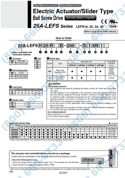
Applicable Stroke Table : Standard 501001502002503003504004505005506006507007508008509009501000Manufacturablestroke range [mm] LEFS16 ——————————50 to 500 LEFS25 ————————50 to 600 LEFS32 ————50 to 800 LEFS40—— 150 to 1000 *P lease consult with SMC for non-standard strokes as they are produced as special orders.How to Orderr Motor typeSymbol T ypeApplicable size Compatiblecontroller/driverLEFS16LEFS25LEFS32LEFS40Nil Step motor(Servo/24 VDC)LECP6LECP1LECP ALECPMJA Servo motor(24 VDC)——LECA6t Lead [mm]Symbol LEFS16LEFS25LEFS32LEFS40A10121620B56810e Motor mounting positionNil In-lineR Right side parallelL Left side parallelw Size16253240y Stroke [mm]5050to to10001000* Refer to the applicable stroke table.ModelStroke[mm]Caution[CE-compliant products]q EMC compliance was tested by combining the electric actuator LEF series and the controllerLEC series.The EMC depends on the configuration of the customer’s control panel and the relationshipwith other electrical equipment and wiring. Therefore, conformity to the EMC directive cannotbe certified for SMC components incorporated into the customer’s equipment under actualoperating conditions. As a result, it is necessary for the customer to verify conformity to theEMC directive for the machinery and equipment as a whole.w For the servo motor (24 VDC) specification, EMC compliance was tested by installing a noisefilter set (LEC-NFA).Refer to page 568 for the noise filter set. Refer to the LECA Operation Manual for installation.e CC-Link direct input type (LECPMJ) is not CE-compliant.[UL-compliant products]When conformity to UL is required, the electric actuator and controller/driver should be used with aUL1310 Class 2 power supply.Series compatible withsecondary batteriesThe actuator and controller/driver are sold as a package.Confirm that the combination of the controller/driver and the actuator is correct.<Check the following before use.>q Check the actuator label for model number (after "25A-"). This matches the controller/driver.w Check Parallel I/O configuration matches (NPN or PNP).* Refer to the operation manual for using the products. Please download it via our website, q wq AccuracyNil Basic typeH High precision type25A-LEFS25w200y6N!0Si1oReHq rBt u1!1!2Refer to page 38 for model selection.Step Motor (Servo/24 VDC)Servo Motor (24 VDC)Electric Actuator/Slider TypeBall Screw Drive Secondary Battery Compatible25A-LEFS Series LEFS16, 25, 32, 40538u Motor optionNil Without option BWith locki Actuator cable type *1Nil Without cable S Standard cable *2RRobotic cable (Flexible cable)*3*1T he standard cable should be used on fixed parts. For using on moving parts, select the robotic cable.*2 O nly available for the motor type “Step motor”.*3 F ix the motor cable protruding from the actuator to keep it unmovable. For details about fixing method, refer to Wiring/Cables in the Electric Actuators Precautions.!1 I/O cable length [m]*1, Communication plugNil Without cable (Without communication plug connector)*31 1.533*255*2S Straight type communication plug connector *3TT-branch type communication plug connector *3*1 W hen “Without controller/driver” is selected for controller/driver types, I/O cable cannot be selected. Refer to page 568 (For LECP6/LECA6), page 582 (For LECP1) or page 596 (For LECP A) if I/O cable is required.*2 W hen “Pulse input type” is selected for controller/driver types, pulse input usable only with differential. Only 1.5 m cables usable with open collector.*3 W hen “CC-Link direct input type” is selected for controller/driver types, I/O cable is not included. Only “Nil”, “S” or “T” can be selected.!2 Controller/Driver mountingNil Screw mounting DDIN rail mounting ** DIN rail is not included. Order it separately.o Actuator cable length [m]Nil Without cable1 1.5335588*A 10*B 15*C20** Produced upon receipt of order (Robotic cable only)!0 Controller/Driver type *1Nil Without controller/driver 6N LECP6/LECA6(Step data input type)NPN 6P PNP 1N LECP1*2(Programless type)NPN 1P PNP MJ LECPMJ *2 *3(CC-Link direct input type)—AN LECPA *2 *4(Pulse input type)NPN APPNP*1 F or details about controller/driver and compatible motor, refer to the compatible controller/driver below.*2 O nly available for the motor type “Step motor”.*3 Not applicable to CE.*4 W hen pulse signals are open collector, order the current limiting resistor (LEC-PA-R-l ) on page 596 separately.Compatible Controller/DriverTypeStep data input typeStep data input typeCC-Link direct input typeProgramless typePulse input typeSeries LECP6LECA6LECPMJLECP1LECPAFeatures Value (Step data) input Standard controllerCC-Link direct inputCapable of setting up operation (step data)without using a PC or teaching boxOperation by pulse signalsCompatible motorStep motor (Servo/24 VDC)Servo motor (24 VDC)Step motor (Servo/24 VDC)Maximum number of step data 64 points14 points—Power supply voltage 24 VDC Reference pagePage 560Page 560Page 600Page 576Page 590* Copper and zinc materials are used for the motors, cables, controllers/drivers.* Specifications and dimensions for the 25A-series are the same as standard products.Motor mounting position: Right side parallelMotor mounting position:In-line539Electric Actuator/Slider TypeBall Screw Drive25A-LEFS SeriesStep Motor (Servo/24 VDC) Servo Motor (24 VDC)Secondary Battery CompatibleLEF LAT LEJ LELLEYLEM LESLEPY LEPSLEY -X5LEC S LEC SS-T LEC YMotor-less11-LEFS 11-LEJSLER LEHLECLZ LC3F225A-。
Doc. no.XM-OMP0001-AHigh Vacuum Angle Valve / Straight ValveXMA/XYA SeriesThank you for purchasing SMC product.For appropriate operation of this product, please read this operation manual thoroughly to understand.Also, refer to the drawing, product information for structure and specification of this product, Confirm operating environment is within specifications.Keep this operation manual with care so that it can be usedat any time.Contents of this operation manual is subject to change without notice.Safety Instructions - - - - - - - - - - - - - - - - - - - - - - - - - - - - 2 1. Product Specific Precautions 1 - - - - - - - - - - - - - - - - - - - - - - - - - - - - 4(Precautions on Design, Selection, Mounting, Piping, Maintenance)2. Product Specific Precautions 2 - - - - - - - - - - - - - - - - - - - - - - - - - - - - 6(Maintenance parts)3. Specifications - - - - - - - - - - - - - - - - - - - - - - - - - - - - 74. Construction / Dimensions - - - - - - - - - - - - - - - - - - - - - - - - - - - - 85. Warranty period and guaranteed range - - - - - - - - - - - - - - - - - - - - - - - - - - - - 106.Parts replacement procedure - - - - - - - - - - - - - - - - - - - - - - - - - - - - 11Safety InstructionsThese safety instructions are intended to prevent hazardous situations and/or equipment damage. These instructions indicate the level of potential hazard with the labels of “Caution,” “Warning” or “Danger.”They are all important notes for safety and must be followed in addition to International Standards (ISO/IEC)*1), and other safety regulations.*1) ISO 4414: Pneumatic fluid power -- General rules relating to systems ISO 4413: Hydraulic fluid power -- General rules relating to systemsIEC 60204-1: Safety of machinery -- Electrical equipment of machines (Part 1: General requirements) ISO 10218-1992: Manipulating industrial robots -- SafetyCaution Caution indicates a hazard with a low level of risk which, if not avoided, could resultin minor or moderate injury.Warning Warning indicates a hazard with a medium level of risk which, if not avoided, could result in death or serious injury. DangerDanger indicates a hazard with a high level of risk which, if not avoided, will resultin death or serious injury .Safety InstructionsLimited warranty and Disclaimer/Compliance RequirementsThe product used is subject to the following “Limited warranty and Disclaimer” and “Compliance Requirements”.Read and accept them before using the product.Common Specific Precautions 1 Be sure to read before handling.●All models1. T he body material is SCS13, the bellows is SUS316L, and other metal seal material isSUS304. Standard seal material in the vacuum section is FKM that can be changed to the other materials (please refer “How to Order”). Use fluids those are compatible with using materials after confirming.2. S elect materials for the actuation pressure piping, and heat resistance for fittings that aresuitable for the applicable operating temperatures.●Models with auto switch1. T he switch section should be kept at the temperature no greater than 60 o C.●All models1. W hen controlling valve responsiveness, take note of the size and length of piping, as well asthe flow rate characteristics of the actuating solenoid valve.2. A ctuating press should be kept within the specified range. 0.4MPa to 0.5MPa is recommended.3. U se within the limits of the operating pressure range.●High temperature types1. I n the case of gases which cause a large amount of deposits, heat the valve body to preventdeposits in the valve.● All models1. I n high humidity environments, keep valves packed until the time of installation.2. I n case with switches, secure the lead wires so that they have sufficient slack, without anyunreasonable force applied to them.3. P erform piping so that excessive force is not applied to the flange sections. In case there isvibration of heavy objects or attachments, secure them so that torque is not applied directly to the flanges.4. V ibration resistance allows for normal operation of up to 30 m/s2(45 to 250Hz), butcontinuous vibration may cause a decline in durability.Arrange piping to avoid excessive vibration or impacts.● High temperature types; (Temperature specifications/H0)1. W hen a valve is to be heated, only the body section should be heated, excluding the bonnetsection.1. B efore mounting, clean the surface of the flange seal and the O-ring with ethanol, etc.2. T here is an indentation of 0.1 to 0.2mm in order to protect the flange seal surface, and itshould be handled so that the seal surface is not damaged in any way.If the fluid or reaction product (deposit) may cause the valve to become unsafe, the valve should be disassembled, cleaned and re-assembled by an operator who has sufficient knowledge and experience (e.g. a specialist).Caution1. When removing deposits from the a valve, take care not to damage any part of its parts.2. Replace the bonnet assembly and the O-ring when the end of its service life is approached. *For details regarding endurance cycles, please reference Section 5 of this Operation manual titled Period and scope of warranty . ( pages 10 )3. If damage is suspected prior to the end of the service life, perform early maintenance.4. SMC specified parts should be used for service. Refer to the Construction / Maintenance parts table.5. When removing the valve seal and external seal, take care not to damage the sealing surfaces. When installing the valve seal and external seal, be sure that the O-ring is not twisted. (Refer to Section 6 Parts Replacement Procedure (pages 11 to 13) for details.)Common Specific Precautions 2 Be sure to read before handlingOnly SMC specified parts should be used. Please refer to operation manual.The bonnet assembly should also be replaced when changing the seal material. Due to the different materials used, changing only the seal may prove inadequate.the magnet for auto switch is necessary, add “-M9//” a t the suffix of the part number. (Not available for hightemperature models)Note2) An auto switch for high temperature is available with a different part number.Note3) List the optional seal material symbol after the model number, except for the standard seal material (FKM: compound No. 1349-80).Note4) The bonnet assembly includes the valve seal.number, except for the standard seal material (FKM: compound no. 1349-80).Note2) Refer to the Construction on the page 9 for the construction numbers.Note3) Please contact SMC if you would like to change the material of the valve seal from ULTIC ARMOR to another material, or from another material to ULTIC ARMOR.Note1) Due to the different materials used, changing only the seal may prove inadequate.Note2) Barrel Perfluoro R is a registered trademark of MATSUMURA OIL Co.,Ltd.Kalrez R is a registered trademark of Dupont Co.,Ltd.Chemraz R is a registered trademark of Greene, Tweed & Co.,ULTIC ARMOR R is a registered trademark of NIPPON VALQUA INDUSTRIES, LTD.Note3) MITSUBISHI CABLE INDUSTRIES, LTD.3. SpecificationsNote1) XYA-16 is not available due to the interference of the flange shapeNote2) The conductance is “molecular flow” measured with an elbow pipe which has the same dimension with each flange.Note3) Air consumed by a reciprocating motion of a cylinder.Note4) Figures in ( ) indicates the weight of CF , conflate fittings.4-1. Construction))(保守部品))AAφGHBCCDφGHBEAφFd(K Flange )φFn (KF Flange )45°XMA Series /Angle ValveXYA Series / Straight ValveThe guaranteed period covers the period which finishes the earliest among 2 million operating cycles [with our durability test conditions], 18 months after shipping from us, and 12 months after starting the use of the product at your place or your c ustomer’s place.If the specification is not kept, or any non-conformance derived from mounting or replace of a device, an assembly, or an O-ring at your place occurs, the guarantee cannot be applied.Note)) The product durability is varied depending on the operating conditions (such as a use with large flow rate).If any failure occurs due to our fault during the guaranteed period, we will guarantee the non-conformance by delivering a substitute in the worst case. However, responsibility of any damage which is led by the product failure is not taken by us.Result of durability test (with the circuit shown on the right)Internal/ external leakage and operation were checked by opening and closing a valve in internally evacuated condition at ordinary temperature (room temperature).It was confirmed that this product satisfied the specification up to 2 million cycles.The test was performed with FKM, the standard sealing material.<Reference>The pumping direction is not limited, but if the pumping creates a flow stream, the durability of the product could be impaired.Therefore, the pumping direction shown on the right figure (bellows side pumping) is recommended. Also, the operating conditions should be checked beforehand because it affects the life.Vacuum pumpBellows side Valve sideChamberRecommended direction of exhaust6-1. PrecautionsBe sure to follow [1. Precautions 1] when disassembling the product for maintenance. Along with the precautions above, comply with the following precautions too.Warning∙If it is expected that product materials may get stuck to the product, ensure safety isassured before handling. It is recommended to wear gloves and a mask.∙Pay attention to the handling of components according to the procedure in the next itemonwards. Do not apply excessive force or impact. This will not only damage the productbut also decrease its performance and life expectancy.∙It is not possible to disassemble the bonnet assembly of this product. If the componentsand assembly are damaged, or damage is expected, exchange the bonnet assemblyitself.∙Do not disassemble the parts that are not explained in this operation manual. Theperformance and life may decrease. Also, it may cause danger.3Bolt124Bottomofdischarge gas.Mounting surface ofO ringBodyO ringO ringBodyBellows holder 1Pilot portBodyBonnet assembly234ValvesSizeX*A-251st Printing :PV 4-14-1, Sotokanda, Chiyoda-ku, Tokyo 101-0021 JAPANTel: + 81 3 5207 8249 Fax: +81 3 5298 5362URL Note: Specifications are subject to change without prior notice and any obligation on the part of the manufacturer.© 2012 SMC Corporation All Rights Reserved。
文件No.VQZ100V-OMT0001电磁阀VQZ系列(先导阀V100搭载)安全注意事项 -------------------------------------------------------------------------------------- 2,3设计注意事项--------------------------------------------------------------------------------------4,5选定---------------------------------------------------------------------------------------------------4,5安装--------------------------------------------------------------------------------------------------6配管-------------------------------------------------------------------------------------------------6配线--------------------------------------------------------------------------------------------------6给油--------------------------------------------------------------------------------------------------6空气源--------------------------------------------------------------------------------------------------7使用环境-----------------------------------------------------------------------------------------------7维修保养-----------------------------------------------------------------------------------------------7产品个别注意事项-----------------------------------------------------------------------------------8~14故障与对策方法-----------------------------------------------------------------------------------15,16安全注意此处所示的注意事项是为了确保您能安这些注意事项,按照危害和损伤的大小都是与安全相关的重要内容,所以除了外,这些内容也请务必遵守。*1) ISO 4414: Pneumatic fluid power ISO 4413: Hydraulic fluid power IEC 60204-1: Safety of machinery ISO 10218-1992: Manipulating indus JIS B 8370: 空气压系统通则 JIS B 8361: 油压系统通则JIS B 9960-1: 机械类的安全性、机械 JIS B 8433-1993: 产业用操作机器人*2) 劳动安全卫生法 等注意注意误操作时, 警告警告 误操作时,危险危险在紧迫的危险①本产品的适合性请由系统设计者或规因为本产品的使用条件多样化,所以析和试验进行判断。
文件编号:AS*-OMA0019-B使用说明书产品名称:单向阀代表番号:AK2000AK4000AK6000•使用前,请仔细阅读本说明书。
•未读完之前,请不要安装本产品。
•请妥善加以保管,确保能随时查阅。
SMC有限公司目录页码1.安全方面的注意事项...............................................................................................1-3 2.用途. (4)3.规格 (4)4.故障与对应措施 (4)5.结构图 (4)联系方式:SMC有限公司〒105 东京都港区新桥1-16-4 朝日银行新桥大厦电话03-3502-82711.安全方面的注意事项本文所列出的注意事项,其目的是为了安全而正确地使用该产品,预防对您或他人造成的危害与损害。
根据这些事项的危害及损害的大小与紧迫程度,做出了明确的规定,并划分成“注意”、“警告”和“危险”这三个等级。
由于它们全都是与安全有关的重要内容,因此,除遵守ISO4414(※1)、JIS B8370(※2)及其它安全规则之外,请务必遵守这些规则。
注意:当操作有误时,可能出现伤及人身的危险,或仅仅造成物质损失。
警告:当操作有误时,可能发生人员死亡或受重伤的重大事故。
危险:出现了紧迫而危险的状态,如果不加以规避,则有可能发生人员死亡或受重伤的严重事故。
※ 1)ISO4414 Pneumatic fluid powor-Recomendations for the application of equipment to transmission and control systems.※ 2)JIS B8370 气压系统通则警告①对于空压设备适应性,应由空压设备的设计者或规格的确定者来做出判断。
本文所记述的产品,其使用条件多种多样,因此,对与相关系统之间的适应性,应由空压设备的设计者或规格的确定者来做出决定,根据需要进行分析或试验。