时刻sk978防盗报警器说明书
- 格式:doc
- 大小:4.01 MB
- 文档页数:24

目录第一章概述 (1)第二章系统构成 (2)2.1 系统构成 (2)2.2 系统基本工作原理 (3)2.3 系统功能特点 (2)2.4 系统软件 (4)第三章产品及技术指标 (5)3.1 电子标签 (5)3.2 检测设备 (6)3.3 预警设备 (7)3.4 中心报警设备 (8)第四章解决方案 (10)4.1 普通岗哨枪支离位报警解决方案 (10)4.2 监狱岗哨枪支离位报警解决方案 (10)4.3 枪支离位报警系统安装示意图 (13)4.4 应用实例 (14)4.4 保全电子枪支离位报警设备成功应用案例 (15)秦皇岛保全电子研究所简介 (16)第一章概述枪支是一种威慑犯罪的特殊工具,虽然各部队对枪支的管理加大了力度,但由于历史原因,现行的枪支管理还是存在很多不尽人意之处,军队枪支管理问题不容忽视。
枪支如果监管不到位将会给国家和社会带来重大安全隐患。
如近年来国内媒体报道的犯罪分子重庆抢枪事件、厦门抢枪事件、上海抢枪事件及吉林省某部队发生的士兵携枪出逃的事件等。
为了加强部队安全防范工作,防止执勤枪支被抢、哨兵被袭击和哨兵携枪逃离部队等情况的发生,加大对执勤枪支的监督管理力度,有效预防武器装备丢失和遭人为破坏,防止涉枪涉弹重大恶性案件发生,维护社会稳定,构建和谐社会,秦皇岛开发区保全电子研究所应部队的具体要求,利用自身独特的技术优势,针对用户的实际需求,在总结现有的枪支防抢系统的基础上,研究开发出了具有独立知识产权的枪支离位报警系统。
该系统操作简单、使用方便、配置合理,具有针对性强、运行稳定、抗干扰力强、无误报、低功耗等优点,充分满足了用户的实际需要。
第二章系统构成2.1系统构成枪支离位报警系统由四部分组成:电子标签、检测设备、预警设备和中心报警设备构成。
如图所示。
其中电子标签安装在值班枪支内;检测设备、预警设备安装在值班岗位;中心报警设备安装在中心值班室。
枪支离位报警系统工作原理示意图一(多级报警)枪支离位报警系统工作原理示意图二(多哨位报警)2.2系统基本工作原理电子标签固化有唯一的电子编码。

EC-5120 时钟显示型120防区报警器使用说明书1系统简介本系统是时钟显示型120防区家用/商用防盗报警系统,功能实用,性价比高、配置齐全、操作简单。
系统采用微电脑处理技术,报警时现场发出120分贝的警报声,同时拨打用户预设的9组电话通知用户。
四位数码管显示报警的方位。
无线连接红外,门磁,烟雾探测器,燃气探测器,紧急按钮等配件。
广泛应用于家庭、工厂、学校、商铺、便利店、财务室、别墅、小区等需要防护的地方。
保护财产不受侵害。
2功能简介■时钟显示型数码显示屏,具有二组闹铃功能,响铃时间可调。
■主机有120组无线防区,每个防区有8种防区类型可供选择,可设普通防区、留守防区、智能防区、紧急防区、关闭防区、门铃防区、迎宾防区、老人求助防区。
■四组定时布撤防功能,每组定时布撤防可选取星期及不同的防区,省去手动频繁布撤防,真正实现智能化全自动控制。
■报警时自动拨打用户设置的9组电话号码;不同的防区可以拨打预设的号码组合,掉电不丢号码。
■ 10秒自定义留言录音。
可在主机上回放录音。
并内嵌人工语音,用户在远程接警时能知道警情发生的地点及防区号。
■异地远程监听功能,并能远程电话布防、撤防。
■无线智能学习配件,学习对码快捷简便,主机可兼容2262及百万组编码,可学习150个遥控器及150个探测器,不同编码的遥控器可以控制特定的分防区。
■集成高精度的时钟芯片,时钟走时准确。
■独有的黑匣子功能,可显示出最近的72条布撤防记录和102条最近的报警记录。
精确显示出报警的时间及防区号。
一、120防区时钟显示型智能防盗报警系统的组成与使用方法布防布防是指家中无人时,需要对报警现场进行全方位的探测警戒;报警器的所有探测器处于工作状态,当有探测源(防盗、防火、煤气泄漏等)触发探测器时,报警系统马上报警。
布防操作后,主机的[布防]灯长亮,同时显示屏上显示“BF”1秒。
遥控操作:按遥控器的[布防]键一次即可。
键盘操作:按主机键盘[布防]键一次即可。
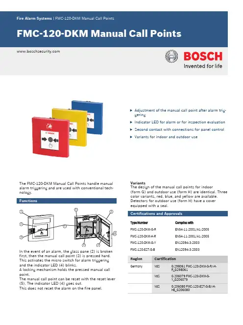
uAdjustment of the manual call point after alarm trig-geringu Indicator LED for alarm or for inspection evaluation u Second contact with connections for panel control uVariants for indoor and outdoor useThe FMC-120-DKM Manual Call Points handle manual alarm triggering and are used with conventional tech-nology.FunctionsIn the event of an alarm, the glass pane (2) is broken first, then the manual call point (3) is pressed hard.This activates the micro switch for alarm triggering and the indicator LED (4) blinks.A locking mechanism holds the pressed manual call point.The manual call point can be reset with the reset lever (5). The indicator LED (4) goes out.This does not reset the alarm on the fire panel.VariantsThe design of the manual call points for indoor(form G) and outdoor use (form H) are identical. Three color variants, red, blue, and yellow are available.Detectors for outdoor use (form H) have a cover equipped with a seal.Certifications and ApprovalsType NumberComplies withFMC‑120‑DKM‑G‑REN54-11:2001/A1:2005FMC‑120‑DKM‑H‑R EN54-11:2001/A1:2005FMC‑120‑DKM‑G‑Y EN12094-3:2003FMC‑120‑EST‑G‑B EN12094-3:2003Installation/Configuration Notes•Manual call points have to be mounted visibly alongescape and rescue routes (e.g. exits, passageways,stairwells) and be easily accessible.•An installation height of 1400 mm ±200 mm, meas-ured from the middle of the manual call point to the floor, must be maintained.•Manual call points must be illuminated sufficientlywith daylight or another light source (including emer-gency lighting, if present).•Max. one test detector may be used for primary lines together with automatic detectors. The test detector is connected at the end of the primary line.•Further standards, guidelines and planning recom-mendations regarding the installation location etc.,should also be taken into consideration (see Fire De-tection manual).•Regulations of local fire departments must be ob-served.Installation•Cables can be inserted surface-mounted or flush-mounted.•Installation in fire hose cabinets is possible in threeways:Pos.Description1Installation depth version 1: 36 mm2Installation depth version 2: 14 mm3Installation depth version 3: approx. 30 mm Technical SpecificationsElectricalMechanicsEnvironmental conditionsOrdering InformationFMC‑120‑DKM‑G‑R Form G, RedManual Call Point for indoor use, indirect alarm trig-gering (type B), conventional technologyOrder number FMC-120-DKM-G-RFMC‑120‑DKM‑H‑R Form H, RedManual Call Point for outdoor use, indirect alarm trig-gering (type B), conventional technologyOrder number FMC-120-DKM-H-RFMC‑120‑DKM‑G‑B Form G, BlueManual Call Point for indoor use, indirect triggering (type B), conventional technologyOrder number FMC-120-DKM-G-BFMC‑120‑DKM‑H‑B Form H, BlueManual Call Point for outdoor use, indirect triggering (type B), conventional technologyOrder number FMC-120-DKM-H-BFMC‑120‑DKM‑G‑Y Form G, YellowManual Call Point for indoor use, indirect triggering (type B), conventional technologyOrder number FMC-120-DKM-G-YFMC‑120‑EST‑G‑B Form G, BlueElectronic Stop Device for indoor use, indirect trigger-ing (type B), conventional technologyOrder number FMC-120-EST-G-BAccessoriesFMX‑FSO‑GLT Punched, Self-adhesive Foil Sets (Blank) For the labeling field of conventional manual call points of the Series FMC‑120, 1 unit = 10 sheets Order number FMX-FSO-GLT FMC‑FST‑DE Printed Labeling Foils for the Upper Label FieldFor yellow and blue manual call points of Series FMC‑120 and FMC‑210, 1 unit = 5 sheetsOrder number FMC-FST-DEFMC‑SPGL‑DEIL Spare GlassesFor manual call points of Series DM, DKM, SKM, FMC‑120 and FMC‑210.1 unit = 5 spare glassesOrder number FMC-SPGL-DEILKey for Fire Detectors Types G and Hmade of red plastic (ASA)Order number FMM-KEY-Form G/Hsurface-mounted/flush-mounted surface-mounted/flush-mounted surface-mounted/flush-mounted16.2 V DC . . . 30 V DC16.2 V DC . . . 30 V DC16.2 V DC . . . 30 V DCspecified by the respective security specified by the respective security specified by the respective security-10°C . . . +55°C-25°C . . . +70°C-10°C . . . +55°Cred, RAL 3001red, RAL 3001blue, RAL 5005FMC‑120‑DKM‑H‑B Form H, Blue FMC‑120‑DKM‑G‑Y Form G, Yellow FMC‑120‑EST‑G‑B Form G, Bluesurface-mounted/flush-mounted surface-mounted/flush-mounted surface-mounted/flush-mounted16.2 V DC . . . 30 V DC16.2 V DC . . . 30 V DC16.2 V DC . . . 30 V DCspecified by the respective security specified by the respective security specified by the respective security-25°C . . . +70°C-10°C . . . +55°C-10°C . . . +55°Cblue, RAL 5005yellow, RAL 1003blue, RAL 5005Represented by:Americas:Europe, Middle East, Africa:Asia-Pacific:Bosch Security Systems, Inc. 130 Perinton Parkway Fairport, New York, 14450, USA Phone: +1 800 289 0096 Fax: +1 585 223 9180***********************.com Bosch Security Systems B.V.P.O. Box 800025600 JB Eindhoven, The NetherlandsPhone: + 31 40 2577 284Fax: +31 40 2577 330******************************Robert Bosch (SEA) Pte Ltd, Security Systems11 Bishan Street 21Singapore 573943Phone: +65 6258 5511Fax: +65 6571 2698*****************************© Bosch Security Systems 2012 | Data subject to change without notice 1291424267 | en, V2, 08. Mar 2012。


智能数字显示报警仪使用说明书Ver.2007.1.智能数字(光柱)显示报警仪通过ISO9001:2000国际质量体系认证中华人民共和国计量器具生产制造许可证通过国际电工委员会IEC61000-4-0:1995标准的电磁兼容试验目 录一、概述 (1)二、智能数字显示报警仪表性能特点 (2)三、技术指标 (2)四、仪表参数设置 (5)五、仪表接线方法 (17)六、仪表选型方法 (26)七、仪表的校准 (27)八、仪表报警的设置 (31)九、仪表的故障处理 (34)十、仪表的安装 (37)十一、仪表的定货与随机附件 (44)概 述本系列智能数字显示仪表采用专用的集成仪表芯片,测量输入及变送输出采用数字校正及自校准技术,测量精确稳定,消除了温漂和时漂引起的测量误差。
本系列仪表采用了表面贴装工艺,并设计了多重保护和隔离设计,并通过EMC电磁兼容性测试,抗干扰能力强、可靠性高,具有很高的性价比。
本系列智能数字显示仪表具有多类型输入可编程功能,一台仪表可以配接不同的输入信号(热电偶/热电阻/线性电压/线性电流/线性电阻/频率等), 同时显示量程、报警控制等可由用户现场设置,可与各类传感器、变送器配合使用,实现对温度、压力、液位、容量、力等物理量的测量显示、调节、报警控制、数据采集和记录,其适用范围非常广泛。
智能数字显示仪表以双排或单排四位LED显示测量值(PV)和设定值(SV),以单色或双色光柱进行测量值百分比的模拟显示,还具有零点和满度修正、冷端补偿、数字滤波、通讯接口、4种报警方式,可选配1~4个继电器报警输出,还可选配变送输出,或标准通讯接口(RS485或RS232C)输出等。
1一、智能数字显示报警仪表性能特点1、专用的集成仪表芯片,具备更为可靠的抗干扰性及稳定性。
2、万能信号输入,通过菜单设置即可配接常用热工信号。
3、可在线修改显示量程、变送输出范围、报警值及报警方式。
4、软、硬件结合的抗干扰模式,有效抑制现场干扰信号。


99防区语音防盗报警器说明书一、使用方法1、布防、撤防:平时主人在家时,可按遥控器上的”撤防“键撤防,主人要离家外出锁好门后,按遥控吕上的“布防”键布防,回家时选取按遥控器上的“撤防”键撤防。
再开锁进门,晚上主人要休息时,可按“S”键进入红外撤防壮态,在这种状态下的红外防区探测器被触发主机不报警(也就是关掉了红外防区,其它防区的报警在打开状态);2、在主机上布防、撤防与红外布防:布防时按“布防键”,再按“9”;撤防时按“撤防键”,再按“0”;红外撤防按主机上的“设防键”,再按“8”;3、当有紧急情况时,按一下遥控器上的“紧急”键,报警系统立即进入紧急报警状态,警号鸣响并自动拨号呼叫,;或按主机面板上的“设防键”,再按“*”,报警系统也同样进入紧急报警状态。
二、接到报警后的处理方法当警情发生后,防盗报警主机会自动抢线拨打设置在防盗报警器里面的电话号码,并根据设置鸣响警号和语音提示报警所处的防区号,如果主机电话占线或不能接通,系统循环拨打三次预设的电话号码后,会自动转拨下一个电话号码;接通报警电话后会听到录音,用户可以不需用输入密码,通过按电话上的数字键对防盗报警器进行远程控制操作。
如果20秒内不按任何操作键,报警主机则会自动挂机退出;1:布防2:撤防5:鸣响警号6:关闭警号7:打开现场监听8:关闭现场所监听9:退出设置并挂机,特别说明一下的是:如果不按”9“号键就挂机,系统会自动拨打下一组报警电话。
三、远程控制操作方法远程控制操作方法可使用任何电话拨打防盗报警系统主机通讯端口所接进的电话号码,系统检测到你所设置的响铃次数后,会自动接通,并提出示输入密码,正确输入密码后可按电话上的数字键对系统进行远程控制(如果密码错误系统会自动挂机),如果20秒内无任何操作,防盗报警系统则自动挂机退出远程控制程序;1、布防2、撤防3、设置系统为有声报警4、设置系统为无声报警5、鸣响警号6、关闭警号7、打开现场监听8、关闭现场监听9、退出设置并挂机四、系统设置方法1、设置报警电话号码设置报警电话号码:按报警器面板上的存储+组号(1-6)+*+电话号码+存诸,报警器最多可设6组报警电话,每组电话号码长度不能超过31位数字,可以是座机电话,也可以是手机,对于使用分机电话的用户,要拨一个号码(比如“9”)才能拨打外线的,则此号码后面加“*”,设置方法如下:设置第一组电话号码:存储+1+*+9+*+13812345678+存储,不过通过我多年做报警器行业的经验,建意大家不要把报警电话设置成分机号码,最好是随身携带、一拨能通的电话,以保障报警电话能正常报警;2、删除电话号码存诸+组号(1-6)+存储,即删除了指定组号的报警电话,例如:要删除第6组接警电话即:存储+6+存储即完成操作3、报警留言录音:录音键+录音+录音键99防区语音防盗报警器在警情触发时,会自动拨打储存在防盗报警主机里面的接警电话,为了让接警人快速地了解报警的方位,我们应在留言录音里面录上报警的详细位置,以便让接警人(如物管、接警中心等)能在第一时间确定方位并迅速赶赴处理;设置录音方法为:按一下主机控制面板上的录音键,主机语音提示“录音”,这时对着防盗报警主机的控制面板开始录音,录音完成后,主机会语音提示“录音成功”即完成录音;录音的最长时间不能超过10秒钟,录音的内容应简洁明了,口词清楚,如:“这里是X幢X单元X号XXX家,现遭非法入侵,请快速协助!”五、报警防区设置及对码1、防区设置99防区语音防盗报警器共有99个防区,每个防区有六种防区的类型(1)、普通防区:主机在布防的状态下才工作,撤防后没有反应(2)、红外防区:可以通过遥控器单独关闭,避免主人在家休息时,红外探测器等装在室内的传感器误报(3)、智能防区:此防区的探测器触发一次系统不会立即报警,要在第一次触发后30秒之内再次触发报才会报警(4)、紧急防区:不管是在布防还是在撤防的状态下,只要探测器一触发就报警,一般用在烟雾、燃气探测器和紧急按钮等;(5)、关闭防区:不管是在布防还是在撤防的状态,探测器触发都不报警;(6)、呼叫防区:在撤防区状态下,呼叫防区的发射器被触发,主机会有语音提出示或数字闪动;防区类型的修改方法是:按设置键+#+设置键+*+防区号(01-99)+N(1-6)+设置(其中的N表示防区类型)系统出厂默认防区类型为:01-59为普通防区;60-79为红外防区;80-89为智能防区;60-99为紧急防区;2、遥控器跟主机对码:按主机上的设置+#+设置+00,这时主机会提出示“学习遥控器”,这时按一下遥控器上任意一按键,听见“嘀”的一声,表示学习对码成功,若还要学习下一个遥控器,直接按下一个遥控器上的任意一键即可,学习完后,按“设置”键退出学习状态,转到正常工作模式,最多可学习20个不同编码的遥控器;3、遥控器的删除:按主机的设置+#+设置+*+00+设置,这时语音会提示“学习成功”。
报警主机使用说明
一、报警主机使用说明
1、开机运行
开机操作:
1、开机前请检查安装操作是否完成,连线是否正确
2.、接通报警主机蓄电池电源
3、接通报警主机交流电源,此时报警主机自动运行,健盘上的状态指示灯和电源指示灯会
常亮表示报警主机开始正常工作
关机操作:
1、关闭报警主机交流电源
2、关闭报警主机蓄电池电源
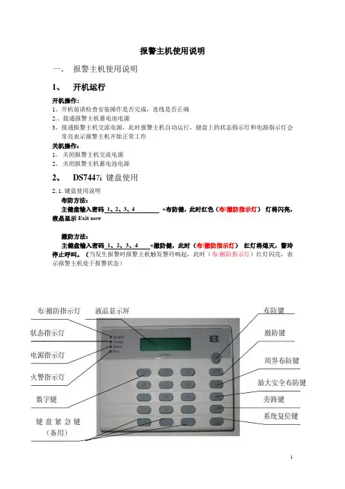
2、DS7447i 键盘使用
2.1.键盘使用说明
布防方法:
主健盘输入密码1、2、3、4 +布防健,此时红色(布/撤防指示灯)灯将闪亮,液晶显示Exit now
撤防方法:
主健盘输入密码1、2、3、4 +撤防健,此时(布/撤防指示灯)红灯将熄灭,警玲停止呼叫。
(当发生报警时报警主机触发警玲响起,此时(布/撤防指示灯)红灯闪亮,表示报警主机处于报警状态)
键盘蜂鸣器的音量控制:同时按“1”和“*”音量增大;同时按“4”和“*”音量减小。
2、故障现象分析及排除
当 DS7400XI 的系统有故障时,电源指示灯灯会闪亮,检查均用指令1234+#87 。
此时DS7447i 键盘将显示系统具体的故障内容。
下面列举一些常见的故障现象及处理方法。
2.1. 键盘故障
2.2. 系统故障
当键盘上电源指示灯绿灯闪亮,并显示 时,表示主机有故障。
此时应按1234+#87来查阅故障事件。
参见下表:。
全功能无线数码智能安防报警系统使用说明书系统简介:本系统为新一代的家用/商用全兼容的安防报警系统,报警主机和配件之间完全无线连接,安装方便。
采用全新的百万组无线编码技术,保密性强。
当有人非法闯入时,主机会发出警报。
同时拨打主人的电话或手机。
配合烟雾感应器和燃气感应器可以防止火灾发生和燃气泄漏。
广泛应用于家庭,商铺,工厂、学校、别墅等区域。
功能特点:◆99个无线防区,每个防区均可独立工作,可设置多达9种工作模式。
◆报警时自动拨打用户设置的6组电话号码;兼容200电话及IP电话。
◆语音留言功能和语音播报防区功能相结合。
◆支持远程异地监听、电话布防、撤防及阻吓功能及独有的远程查询功能。
◆智能学习各种无线配件,快捷方便,兼容2262及百万组编码。
方便用户扩展功能。
◆停电报警功能,停电后主机可以拨打预设的电话号码,通知用户;用户也可远程查询家里的是否停电。
◆内置高精度定时芯片,具有九组定时功能。
可以定制布防,撤防或设置成闹钟;更具有独有的整点报时功能。
断电后时间设置不消失。
◆超强的语音查询功能,可以查询设置的各组电话号码、最近的报警记录、防区类型、定时设置等。
◆全程语音指导,用户操作及远程控制时更方便。
◆全功能设计。
本系统内置迎宾器,门铃和呼叫器功能。
适合各种商业用途。
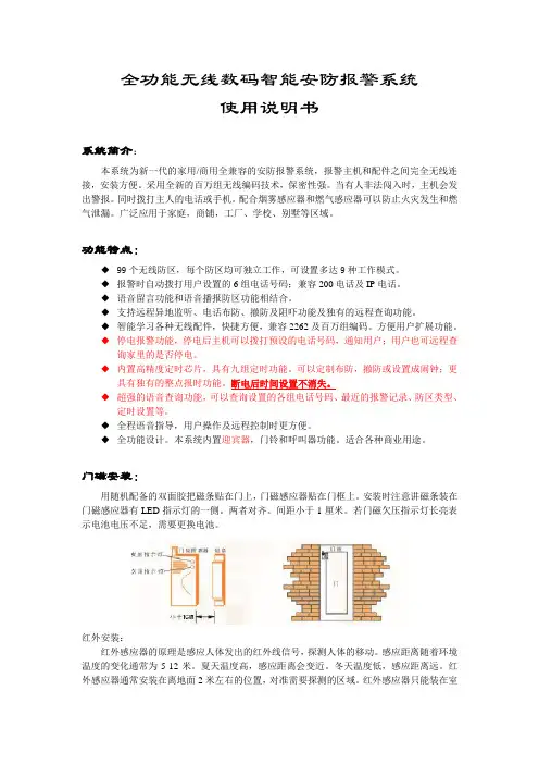
门磁安装:用随机配备的双面胶把磁条贴在门上,门磁感应器贴在门框上。
安装时注意讲磁条装在门磁感应器有LED指示灯的一侧。
两者对齐。
间距小于1厘米。
若门磁欠压指示灯长亮表示电池电压不足,需要更换电池。
红外安装:红外感应器的原理是感应人体发出的红外线信号,探测人体的移动。
感应距离随着环境温度的变化通常为5-12米。
夏天温度高,感应距离会变近。
冬天温度低,感应距离远。
红外感应器通常安装在离地面2米左右的位置,对准需要探测的区域。
红外感应器只能装在室内。
不要对着太阳光、窗户、空调等温度快速变化的地方。
红外感应器需要在启动3-5分钟后进入稳定状态。
快速使用:主机的基本操作:遥控器布防及撤防:主人离家外出时按遥控器上的“布防”键设防,主机进入工作状态。

Kidde Catalog u Small Building Fire Alarm Solutions Technology that saves livesOverviewKidde brand intelligent life safety systems offer the power of high-end intelligent processing in configurations that deliver uncompli-cated solutions for small to mid-sized applications. With intelligent detection, rotary addressing, automatic device mapping, optional Ethernet® connectivity, and a full line of easily-configured option cards and modules, these flexible systems offers offer versatility that benefits building owners and contractors alike.The FX-64 provides one Class B intelligent device loop that sup-ports up to 64 device addresses, and two Class B Notification Ap-pliance Circuits (NACs). Optional Class A device wiring is available with the use of a module.The FX-1000provides one Class A or Class B intelligent device loop that supports up to 250 device addresses. Loop controller modules may be added in combination to expand total system capacity in 250-point increments to up to 1,000 device addresses. The FX-1000 panel includes four NACs that may be wired for either Class A or Class B operation.The RZI16-2RS module adds even more capacity to FX instal-lations by adding up to 16 conventional device circuits and two additional notification appliance circuits. This makes them an ideal retrofit solution that can accommodate new intelligent detectors, as well as existing conventional devices.Features• Auto-programming speeds installation time• Form C contacts for alarm and trouble, Form A for supervisory • Easy-to-configure rotary addressing• Optional Ethernet port for diagnostics, programming and a variety of system reports• Two programmable switches with LEDs and custom labeling • Supports horn silence over two wires, and UL 1971-compliant strobe synchronization• Class B or Class A wiring• Ground fault detection by module• Supports up to eight serial annunciators, (LCD, LED-only, and graphic interface)• Can use existing wiring for most retrofit applications• Upload/download remotely or locally• Two-level maintenance alert reporting• Pre-alarm and alarm verification by point• Adjustable detector sensitivity• 4 x 20 character backlit LCD display• Optional earthquake hardening: seismic Importance Factor 1.5• Standalone operation• Transmission test frequency by hourIntelligent FireAlarm SystemsFX-64, FX-10007165-1657:0244S3000COA 6231Page 1 of 8 D A T A S H E E T K85005-0137Not to be used for installation purposes. Issue 1Page 2 of 8 D A T A S H E E TK85005-0137Not to be used for installation purposes. Issue 1ApplicationKidde FX Series life safety systems are powerful intelligent solu-tions for small to mid-sized buildings. Advanced analog technology delivers the benefits of flexible system installation, while clean and easy-to-operate user interfaces make panel operation and system maintenance quick and intuitive.Reliability you can count onThe inherent fault-tolerant characteristics of Analog/Address-able Technology boosts the reliability of Kidde fire alarm systems. When combined with FX Series smoke and heat detectors, these systems deliver a level of dependability not previously available for small to mid-sized applications. All Kidde systems are built to exacting reliability benchmarks and meet international standards for quality, in addition to agency listings for dependability.Flexibility built right inTwo fully-programmable front panel switch/LED combinations pro-vide an added measure of flexibility. Their slide-in labels take the mystery out of custom applications, and present a clean finished appearance.Perfect for retrofitsKidde FX Series control panels are particularly well-suited to retrofit applications. All connections are made over standard wiring – no shielded cable required. This means that in most situations exist-ing wiring can be used to upgrade a legacy control panel to FX technology without the expense or disruption of rewiring the entire building. FX control panels also support the ingenious RZI16-2RSDimensions(1) Surface Mounting Holes (2) Semi-flush mounting Holes(3) Backbox with Door Attached(4) Backbox with door and trim kit attached.provides 0.75 inches (1.9 cm) of trim to the top, bottom, and sides of the backbox.Programming and remote diagnosticsKidde FX Series life safety systems are simple to set up, yet offer advanced programming features that put these small building pan-els into a class of their own. The auto programming feature quickly gets the panel operational using factory default settings. Basic zone and point settings can be programmed easily through the front panel interface, so the system is up and running in no time.The FX series panels can also interface to a PC running the FX-CU configuration utility software. This option offers full system con-figuration in the familiar Windows ® operating environment. Con-nection is typically made to a laptop through the panel’s optional RS-232 communications port, which can also be used to connect a system printer.Among the many innovative features of FX Series control panels is the optional network card. This module provides a standard 10/100 Base T Ethernet ® network connection that permits access to the control panel from any remote location with the correct communications protocols. The connection can be used to down-load to the panel from the FX-CU, or upload and view system reports using the FX-CU.Available system reports include:• Correlation groups • Device details • Device maintenance • History• Internal status • System configuration • System status • Walk test• Dialerzone module, which adds up to 16 conventional circuits and two NACs. This combination easily accommodates new intelligent detection alongside existing conventional circuits, making it an unbeatable solution in the retrofit market.Signals with a differenceKidde FX Series NACs are configurable to fully support renowned Genesis Series notification appliances. When used with FX control panels these devices offer precision synchronization of strobes to UL 1971 standards — without the need for external modules. This feature also allows connected horns to be silenced while strobes on the same two-wire circuit continue to flash until the panel is reset.Clear-cut remote annunciationRemote annunciation is a strong suit of the FX Series fire alarm systems. Up to eight annunciators can be installed on a single system. Compatible annunciators include a range of LED and LCD models that provide zone or point annunciation, as well as com-mon control capabilities.FX control panels also supports graphic annunciation with optional Graphic Annunciator interface modules. Each interface provides common control, indicators, and 32 LEDs.A complete line of accessoriesFX Series life safety systems are supported by a complete line of analog/addressable detectors, modules and related equipment. Consult the Ordering Information section for details.Page 3 of 8 D A T A S H E E TK85005-0137Not to be used for installation purposes. Issue 1Ethernet (SA-ETH)DACT/Dialer (SA-DACT)RS-232 (SA-232)Relays: Two Form C, one Form AUp to 20,000 feet of wiring.Two Class B or two optional Class A NACsOptional 10 A or 6.5 A Booster Power SupplyUp to eight remote annunciatorsLoop supports up to 64 intelligent devices of any type.Each FX-1000 panel has room for up to two loop controller Four Class B or two optional Class A NACsUp to 20,000 feet of wiring per loopFour Class B or two optional Class A NACsOptional 10 A or 6.5 A BoosterUp to eight remote annunciatorsUp to 125 sensors and 125 modules per loopEthernet (SA-ETH)Standard Loop: 250 points (one expansion slot)FX-SLC1 Expander Loop: 250 points (one expansion slot)FX-SLC2 Expander, Loop 1 of 2:FX-SLC2 Expander, Loop 2 of 2:Any combination of two single- or dual-loop modules(one expansion slot)Sixteen Conventional IDCs,two additional NACs with RZI16-2RS moduleFX-64Panel Layout2345678Page 4 of 8 D A T A S H E E TK85005-0137Not to be used for installation purposes. Issue 1Annunciator loop (TB4)The control panel provides a connection for up to eight serially driven and supervised remote annunciators.Circuit specifications Device loops Class B (Style Y) or Class A (Style Z)Circuit voltage 2.55 VCircuit current 30 mA maxCircuit impedanceUp to 8 annunciators or 4000 feet +–TB4+–C hanne l 1 C hanne l 2C H 1 (+) I N C H 1 (-) I N C H 2 (+) I N C H 2 (-) I NAnn u nciat o rTB4+–C hanne l 1 C hanne l 2C H 1 (+) I N C H 1 (-) I N C H 2 (+) I NC H 2 (-) I NAnn u nciat o rTB4+–C hanne l 1 C hanne l 2C H 1 (+) I NC H 1 (-) I NC H 2 (+) I NC H 2 (-) I NAnn u nciat o r+–TB4+–C hanne l 1 C hanne l 2C H 1 (+) I N C H 1 (-) I N C H 2 (+) I N C H 2 (-) I NAnn u nciat o rClass BClass AAlarm, trouble, and supervisory relay (TB3)The trouble relay is normally-open, held closed, and opens on any trouble event or when the panel is de-energized. The supervisory relay is normally-open, and closes on any supervisory event. The alarm relay changes over on any alarm event.Relay specificationsRelay circuits can only be connected to power-limited sources.Auxiliary & Smoke power outputs (TB3)The control panel provides two auxiliary poweroutputs that can be used for powering ancillaryequipment such as remote annunciators and two wire smoke detectors. Aux 2 can be software selected to operate continuously. The circuit is supervised for shorts and grounds.rangeResettable circuit (Aux power 2)24 VDC nominal at 500 mA Use this circuit for poweringtwo-wire smoke detectors.Continuous circuit (Aux power 1)24 VDC nominal at 500 mA. Note: Any current above 0.5 amp connected to both Aux 1 and 2 will reduce the total available NAC power by that amount.Notification appliance circuits (TB2)FX-1000 control panels come equipped with four notification ap-pliance circuits. FX-64 control panels come with two NACs. Each circuit can be individually configured for continuous, temporal,synchronized, and coded output.Class A wiringTB2TB6NAC1-NAC2+NAC2-NAC1+++++++------Class B wiringTB2TB6EOLRNAC3-NAC4+NAC4-NAC3+EOLRNAC1-NAC2+NAC2-NAC1+++++++++--------Marking indicates output signal polarity when the circuit is active. Polarity reverses when the circuit is not active. Wire notification appliances accordingly. Notification appliance polarity shown in active state.Wiring & ConfigurationDevice loopThe system provides one device loop circuit with a total capacity of 125 detectors and 125 module addresses. The loop circuit is supervised for opens, shorts, and grounds.Class A wiringClass B wiringTB3(1)NO NCNC NONO(4)(3)(2)(1) Trouble (2) Supervisory (3) Alarm (4) Smoke/AuxSingle and Dual Loop Controller CardsThe FX-SLC1 is a single loop controller card that can be used with the FX-64 as a replacement for the standard 64-point loop, or with the FX-1000 as a 250-point expansion module.The FX-SLC2 is a 500-point dual loop controller card for theFX-1000 that provides two IDC circuits, each with 125 detectoraddresses and 125 module addresses.Communication LineVoltageMax. 20.6 V peak-to-peakTerminal Rating12 to 18 AWG (0.75 to 2.5 mm2)Circuit Current0.5 A max.Max total loopresistance66 ΩMax total loopcapacitance0.5 μFIsolators64 isolators maximum per loop (total bothisolator bases and modules)Ground FaultImpedance0 to 5 kΩOperating Environment32 to 120°F (0 to 49°C)0 to 93% noncondensing at 90°F (32°C)The RZI16-2RS Addressable Remote Zone Interface Module is anaddressable device that provides connections for sixteen Class BInitiating Device Circuits and two Class B Supervised OutputCircuits. The inputs and outputs can be configured individually forseveral device types.The device address is set using the two rotary switches located onthe front of the module. The RZI16-2RS requires 18 consecutiveaddresses on the Signaling Line Circuit (SLC).The RZI16-2RS incorporates two 8-segment DIP switches thatare used to select the Alarm or Supervisory default device type foreach of the 16 IDC circuits. The module also includes one 4-seg-ment DIP switch used to select the default Relay or NAC outputdevice type. Device types other than the default are accomplishedthrough programming.24V/Aux nominal:Supervisory current:Alarm current:24V/Aux minimum:24V/Aux maximum:NAC1, NAC2 nominal:24 VDC250 mA at 24 VDC nominal1000 mA18.4 VDC26.4 VDC24 VDCCurrentStandby currentfor 4.7 k EOL (U.S.)Standby current for3.9 k EOL (Canada)Alarm currentat nominal voltage4.8 mA/ circuit5.7 mA/ circuit31.1 mA/ circuitRelay outputsQuantityType Rating (pilot duty)2Programmable 24 VDC at 2.5 AInput circuit wiringresistance25 Ω per wireInitiating device circuitsQuantityEOL resistorZone voltageAlarm currentAlarm impedance rangeTrouble impedance range164.7 kΩ (U.S.); 3.9 kΩ Canada22.78 V for 4.7 kΩ (U.S.)22.08 V for 3.9 kΩ (Canada)31.1 mA/ channel at nominal voltage< 680 Ω> 5.55 kΩSupervised output circuitsEOL resistorQuantityShort circuit detectionOpen circuit detectionContact ratings15 kΩ2< 2.6 kΩ> 61.9 kΩ24 VDC at 2.5 A (5 A for two NACs)Compatible cabinets MFC(A), FX-1000, APSSA-ETH Ethernet Interface CardTo networkconnectionThe SA-ETH card provides astandard 10/100 Base T Ether-net network connection forconnecting to an intranet, a localnetwork, or the Internet. Thecard can be used to downloadconfiguration programming fromthe FX-CU to the panel over thenetwork.The Ethernet card is installed onthe plastic assembly and con-nects to the main circuit boardvia a ribbon cable.Operating environmentTemperatureHumidity32 to 120°F (0 to 49°C)0 to 93% RH, noncondensing at 90°F(32°C)Option CardsKidde FX Series panels are supported by a complete line of mod-ules and related equipment that enhance performance and extendsystem capabilities. Option cards plug directly into the controlpanel main circuit board or are connected to it with a ribbon cable.After installation, terminals remain accessible. The cabinet pro-vides ample room for wire routing, keeping wiring neat at all times.Page 5 of 8 D A T A S H E E T K85005-0137Not to be used for installation purposes. Issue 1Page 6 of 8 D A T A S H E E TK85005-0137Not to be used for installation purposes. Issue 1SA-232 RS-232 interfaceSA-232 wiringThe SA-232 card provides an RS-232 in-terface with FX panels. It can be used for connecting a printer to the control panel to print system events. The card also can be used for connecting a computer to download a configuration program from the FX-CU to the control panel.The RS-232 card is installed on the plas-tic assembly and connects to the main circuit board via a ribboncable.Terminal rating12 to18 AWG (0.75 to 2.5 sq mm)Operating environmentTemperatureHumidity32 to 120°F (0 to 49°C)0 to 93% RH, noncondensing at 90°F (32°C)SA-DACT DialerThe SA-DACT provides communications between the control panel and the central station over a telephone line system. It transmits system status changes (events) to a compatible digital alarm communicator receiver over the public switched telephone network. The dialer is capable of single, dual, or split reporting of events to two different account and telephone numbers. The modem feature of the SA-DACT can also be used for uploading and downloading panel configuration, history, and current status to a PC running the FX-CU.jackPhonewiringThe dialer phone lines connect to connectors on the dialer’s maincircuit board. Phone line 1 connects to connector J4 and phone line 2 connects to connector J1.The SA-DACT queues mes-sages and transmits them based on priority (alarm, supervisory, trouble, and monitor). Activations are transmitted before restora-tions.The SA-DACT is installed on the plastic assembly and connects tothe main circuit board via a ribbon cable.switched networkPhone line connector RJ-31/38X (C31/38X)Communication formats Contact ID (SIA DC-05)Operating environmentTemperature Humidity 32 to 120°F (0 to 49°C)0 to 93% RH, noncondensing at 90°F(32°C)Ademco 685Contact ID FBIICP220Contact ID Osborne-Hoffman OH 2000Contact ID BoschD6600Contact ID Silent Knight 9800Contact ID Sur-GardSG-MLR1, MLR2Contact IDSA-CLA Class A Module (FX-64 only)The SA-CLA card provides Class A capability for NAC wiring. Its terminal block provides the wiring connection for NAC return wiring. The card is required for annunciator Class A wiring even though this wiring does not return to the SA-CLA card. The SA-CLA is compatible with FX-64 control panels only. FX-1000 panels are Class A Ready. The SA-CLA is installed directly to the control panel circuit board using its plastic standoffs and plug connection.Operating current 3.75 A FWR total at 120/230 VAC 60 Hz3.0 A FWR total at 230 VAC 50 Hz 2.5 A max per circuitCircuit impedance 26 ohms, 0.35uF Terminal rating 12 to18 AWG (0.75 to 2.5 sq mm)Operating environmentTemperature Humidity 32 to 120°F (0 to 49°C)0 to 93% RH, noncondensing at 90°F(32°C)D16L-Fa LED Display Expander (FX-1000 only)The D16L-FA LED Display Expander provides LED annuncia-tion for up to 16 zones. It provides two LEDs for each zone. Two D16L-FA LED display expanders can be installed in each FX-1000 panel.(1) LED 1(2) LED 2(3) LED Expander 1(4) LED Expander 2(5) Alarm/non-alarmand trouble zone LEDsSpecificationsPage 7 of 8 D A T A S H E E T K85005-0137Not to be used for installation purposes. Issue 1Technology that saves livesContact us...Email:*****************.comWeb: /EngineeredSystems Kidde is a UTC brand.1016 Corporate Park DriveMebane, NC 27302© 2016 United Technologies Corporation. All rights reserved.Ordering Information260097RS232 cable, 4 conductor, DB9 PC interfacePage 8 of 8 D A T A S H E E T K85005-0137Not to be used for installation purposes. Issue 110-11-16。

DIGI*TRACD T A001-0901DIGI*TRAC Annunciator Guide iiDTA001-0901, September, 2001Copyright © 2001 Hirsch Electronics Corporation. All rights reserved. S cramblePad ® is a registered mark of Hirsch Electronics Corporation. DIGI*TRAC™, MATCH™, S cramblePad, S crambleProx ® and SCRAMBLE*NET™ (abbreviated S*NET) are all trademarks of Hirsch Electronics Corporation.Hirsch Electronics Corporation1900 East Carnegie AvenueBuilding BSanta Ana, CA 92705-5520Phone:949-250-8888 or 888-809-8880Fax:949-250-7372Web:DTA001-0901Getting HelpIf you encounter a problem that is not discussed in this guide and youneed technical support, do the following:1.Contact your local dealer or the provider of this product.2.If your dealer is not available, contact Hirsch Technical Supportdirectly. This can be done in a number of ways:M a il il::Hirsch Electronics Corporation1900 East Carnegie AvenueBuilding BSanta Ana, CA 92705-5520Attn: Technical ServicesV o i c e:(877) HIRSCHX (technical queue)(888) 809-8880F a x:(949) 250-7362E m a il il: : :*****************************W W W:Whenever you call your local dealer or Hirsch, be sure to have yourregistration material, serial number and software version numberavailable.For future reference, record these numbers here.Serial Number: _________________________________Version Number: ________________________________Dealer: ________________________________________Dealer Phone #: ________________________________CCM Rev/Version #: _____________________________Getting Help iiiDIGI*TRAC Annunciator Guideiv Getting HelpDTA001-09011IntroductionThe DIGI*TRAC Annunciator (DTA) is used to monitor basic security functions—such as alarm, input, and relay status. It provides a local display of critical information near or outside the protected area.On the back of the Annunciator is an integrated MATCH2 board that communicates with the controller using the same digital channel as both the ScramblePad and MATCH.F i g u r e e 11: : D D IG I *T R A C C A A n n un unc c i a t o r r – – – S S i d e e V V i e wThe front of the Annunciator includes both a four-line, 20-character non-backlit LCD display and four status request buttons.The status request buttons are smart keys that change their meaning according to the current dialog displayed on the LCD screen abovethe keys.IntegratedMATCH-2DIGI*TRAC Annunciator User’s Guide 2Both a picture and an illustration of this front panel is shown in Figure 2:F i g u r e e 22: : D D IG I *T R A C C A A n n un unc c i a t o r r – – – F F r on ont t t V V i e wThese keys are used for status requests only and cannot issue commands of any sort.Status requests supported are:OAlarm Log Display from the Controller's Alarm Buffer (holds last 256 alarms)OCurrent Relay Status (to determine whether a door is locked)O Current Input Status (to determine where a door is closed or adevice is secured)This unit requires CCM 7.0 but does not require any host software for setup or operation. It is ideal for lobbies and other passages outside of the secured area where an individual can confirm that theprotected area is secure (such as locked and ready to leave).4-line LCD screen4-button keyboardDTA001-0901Installing the AnnunciatorThe DIGI*TRAC Annunciator comes pre-assembled with the MATCH2installed on the back of the DTA. There are several optional coverplates available as well as surface mount and flush mount backboxes.The DTA is a secure annunciator and requires a ScramblePad code orcard to activate the display.A simplified example of an Annunciator installation looks like Figure 3:F i g u r e e 33: : T T y p i c a l l A A n n u n c i a t o r r I I n s t a l l a t i o n3DIGI*TRAC Annunciator User’s Guide 4 A more complex example is shown in Figure 4:F i g u r e e 44: : A A n n un unc c i a t o r r E E x a m p l eThis example represents the way in which an annunciator can be used to monitor activity within a given area—in this case, three rooms incorporating readers, keypads, relays, motion detectors, amongst other devices—and supply alarm and event information specific to the entry and exit of personnel to/from that area.The required components include:ODIGI*TRAC Controller OAnnunciator O Keypad or Card ReaderMost of the installation and configuration requirements for theAnnunciator are identical to those you would observe for the MATCH2 board (refer to “MATCH Interface Installation” on page 7-74 in the DIGI*TRAC Design and Installation Guidefor more details).DTA001-09015T o install the Annunciator:1.Locate the place where you want to put the DTA. This should belocated near the ScramblePad/ScrambleProx and/or reader that will authorize the DTA’s use.e the selected surface mount plate or flush mount back box to position and draw an outline on the wall.3.Either secure the surface mount box to the wall or cut a hole for the flush mount box, then route the appropriate wires into the box.4.T urn off the power to the area or wall where you want to install the Annunciator.5.Depending on the type of device you are using, connect the device in one of these ways.If you are using a ScramblePad to activate the Annunciator :a.Route the wire from the Controller to the D*TRAC port on the DTA’s MATCH board as shown in Figure 5. Connect the wire to the port.F i g u r e e 55: : C C on onn n e c t t C C on ont t r o ll lle e r r a a n d d K K e y p a d d t t o o t t h e e A A n n u n c i a t o rThe DTA communicates with the MATCH2 via its RS-232 port (P2) and draws its power from one of the MATCH2's reader channels (C2). This comes pre-wired from the factory.Connecting a ScramblePad SCRAMBLEPAD Keypad Port D*TRAC PortDIGI*TRAC Controller Back of AnnunciatorDIGI*TRAC Annunciator User’s Guide 6 b.Connect an extension cable from the Keypad port on the DTA’s MATCH2 board.If you are connecting a reader to the Annunciator : a.Relocate the connector on Port 1 (P1) of the MATCH2 to Port2 (P2). This is only used as a power source for the DTA.b.Connect the Reader to Port 1 on the DTA’s MATCH2 board as shown in the example in Figure 6.F i g u r e e 66: : C C on onn n e c t i n g g R R e a d e r r t t o o t t h e e D D T AThis picture shows a specific type of proximity reader(CR20L) which is also used in the DS47L-SPX. Your reader and wiring specifications may differ from this picture.Connecting aReaderSOLDER &HEAT SHRINK ALL SPLICESCR20L-125-6005(HID# 6005)7If you are using a ScrambleProx as the keypad , follow these instructions (as shown in the example in Figure 7):a.Connect an extension cable from the Keypad port on the back of the ScrambleProx to the Keypad port on the DTA’s MATCH2 board.b.Relocate the connector on Port 1 of the MATCH2 to Port 2. This is only used as a power source for the DTA.c.Connect the DIGI*TRAC controller cable to the D*TRAC port on the DTA MATCH2 board.d.Disconnect the proximity reader connector from Port 1 on the ScrambleProx.e.If necessary, use an extension cable (Hirsch# MCRH) toconnect the loose reader cable from Port 1 on theScrambleProx to Port 1 on the MATCH2.Follow the connection chart shown in Figure 7.F i g u r e e 77: : C C on onn n e c t i n g g a a a S S c r a m b l e P r o x x t t o o a a a D D T AUsing aScrambleProxRoute keypad cable from theScrambleProx to the Keypad porton the DTA ➀from Port 1 on the ScrambleProx and connect it to Port 1 on the back of the DTA. If necessary , fabricate a cable for this purpose.6.If you are using a keypad, route the data wire from theScramblePad or ScrambleProx keypad to the Keypad port on theDTA’s MATCH2 board as shown in Figure 5.The ScramblePad or reader used to activate the DTA canalso be used as a standard entry access device. TheScrambleProx can be used as long as its integral readeris connected to the DTA’s Port 1 of the MA TCH2 instead ofPort 1 on the ScrambleProx as shipped from the factory.7.Follow the same power cable requirements as you would use toconnect an independent MATCH2. Ordinarily the controllerprovides sufficient power to operate attached ScramblePads andMATCH2 interfaces; however, there are conditions which requiremore power than the controller can supply.8.Secure the DTA to the box or plate.Once connected, the operator accesses the Annunciator by eitherentering a special code into the connected ScramblePad or using aspecial card on the attached reader or ScrambleProx. A simple menuappears on the Annunciator LED. The operator then follows the menuto access the information they require.8Assigning Annunciator PrivilegesThe process of enabling the DTA for the controller depends on thehost PC software used. There are three methods for assigningAnnunciator privileges to a user:O Keypad assignmentO SAM assignmentO Velocity assignmentEach of these methods is discussed in this section.Keypad AssignmentT o assign Annunciator privileges from a ScramblePad:1.From an attached ScramblePad, enter program mode.e the following command and syntax to assign Annunciatorprivileges to a user:44*1*User Number*Codewhere User Number is the number assigned to this user and theCode is the PIN number assigned to this user at this door toactivate the DTA.You can also use this command to assign Annunciator privilegesthrough the SAM diagnostics window or the MOMENTUM Hirsch T estT ool.SAM AssignmentT o assign Annunciator privileges using SAM:1.Access the Add/Edit User Group worksheet by selecting A A ddup in the Groups menu, or press F F3 3 A A d d.G r o up2.Select the User Group you want to enable for this function. TheAdd/Edit User Group dialog box appears.3.Either define a new group or select an existing user group.4.Click the “Function” field arrow. An option list appears.m C C onont t r o l button. A list of available alarm functions5.Select the A A l a r mappears.m C C a n c e l function.6.Select the A A l a r m9107.Select the access zone and the code extension you require to activate this DTA.F i g u r e e 88: : P P r o g r a mm mmi i n g g t t h e e C C o n t r o l l e r r U U s i n g g S S AM Select Alarm Cancel fromSelect the AccessZone you need forthis function Select the ID Form at and Code extension you want to activate the DTAthe Alarm Control optionlistVelocity AssignmentIf you are using Velocity, you can assign an operator the ability to usethe Annunciator in one of two ways:O Define a Function GroupO Define a user credential through Enrollment ManagerCreating a Function Group is the best way if you plan to assignAnnunciator privileges to more than one user.Function Group AssignmentT o assign Annunciator privileges for a group through Function Groups:1.From the Velocity system tree, select the Function Groups file. Alist of all currently-defined function groups and the Add NewFunction Group button appear in the right hand Componentspane.on G G r ououp p button to createdd N N e w w F F ununc c t i on2.Either double click the A A dda new function group, or double click an existing function group.The Function Group Properties dialog box appears.3.If this is a new function group, enter a new function group namein the Name field. If this is an existing function group, a namealready appears.dd.... button to add the required code extension to this4.Click the A A ddfunction group. The Define Extension dialog box appears.5.In the “Extension Digits” field, enter one or two digits.6.In the “Function Category” field, select A A l a r m from the pull-downoption list.m C C a n c e l from the pull-down7.From the “Function” field, select A A l a r moption list.8.From the “Controller” combo box, select the currently-definedcontroller to which this extension code applies.9.From the “Control Zone” combo box, select the currently-definedcontrol zone or master control zone during which this extensiondigit applies.dd to register the new extension digit in the lower window.10.Click A A dd11.Click O O K to return to the Function Group Properties dialog box.12.Click O O K to return to the main menu.11ing Function Groups in the Administrative Mode, assign thisfunction group to the specified user(s) on the Function property page.F i g u r e e 99: : A A s s i g n i n g g A A n nu nun n c i a t o r r P P r i v i l e g e s s u u s i n g g V V e l o c i t y ’s s F F u n c t i o n nG G r o up Click A A dd dd....Select A A l a r m &A l a r m m C C a n c e lClick O O KClick A A dd dd....Single Credential AssignmentT o assign Annunciator privileges for a single credential through Enrollment Manager:1.Open the Enrollment Manager.2.Select the person to whom Annunciator privileges should beassigned.dd N N e w3.Create a new credential by double clicking the A A ddC r e d e n t i a l button. The Credential Properties dialog box for theselected person appears.4.Fill out this form as required making sure to supply a code orcard.5.Click the Function tab.unc c t i o n radio button.6.If not already selected, click the S S i n g l e e F F un7.In the “Function Category” field, select A A l a r m from the pull-downoption list.m C C a n c e l from the pull-down 8.From the “Function” field, select A A l a r moption list.9.From the “Controller” combo box, select the currently-definedcontroller to which this extension code applies.10.From the “Control Zone” combo box, select the currently-definedcontrol zone or master control zone during which this extension digit applies.dd to register the new extension digit in the lower window.11.Click A A dd12.Click O O K to return to the Enrollment Manager main menu. Thenew credential appears in the Credential pane for the selected user.13.Click O O K to return to the main menu.1314F i g u r e e 110: : A A s s i g n i n g g A A n nu nun n c i a t o r r P P r i v i l e g e s s t t o o a a a C C r e d e n t i a l l u u s i n g g E E n r o l l m e n t t M M a n ag age er Click Function T abthen A A l a r m &A l a r m m C C a n c e lEnter code and/orcard15Operating the AnnunciatorThe following procedure shows you how to use the Annunciator.1.Go to the keypad (either ScramblePad or ScrambleProx) or cardreader connected to the DTA. This normally will be the keypad or reader mounted closest to the DTA.Whenever the DTA is not activated, it displays the time and day like this example:F i g u r e e 111: : I I n a c t i v a t e d d D D T A A S S c r ee een n2.Perform one of these procedures:•At the keypad, enter your special DTA-activation code. This is often a code extension (SAM) or function group (Velocity).•At a reader, swipe your special DTA-activation card.Your regular access code/card alone cannot activate the DTA. The code/card must be used with an extension digit or function group digits. The system administrator must issue you this special code/card or extension to activate the DTA.The DTA is activated. The DTA’s screen displays the initial screen like Figure 12.F i g u r e e 112: : A A n n un unc c i a t o r r M M a i n n M M e nuEND ALMLOG INP STAT RELAYSTAT16These options are:3.Press the button for the option you want.A list of the current alarms or status points (input or relay) for the connected controller appear.You will only see the alarms or status for the controllerconnected to this DTA. No other controller’s status is displayed.O If you press the ALM LOG button, a screen like Figure 13 appears:F i g u r e e 113: : A A l a r m m L L o g g M M e n uOnly one alarm at a time can be displayed.P r e s s s t t h i s b s button to utton to utton to::ENDEnd the current session and return the DTA to inactive mode.ALM LOGDisplay the log of all alarms experienced by this controller only.INP STATDisplay the current status for all inputs connected to this controller only.RELAY STATDisplay the current status for all relays(outputs) connected to this controller only.BACK FWD SAVEERASEO If you press INP STAT, a screen like Figure 14 appears:F i g u r e e 114: : I I n p u t t S S t a t u s s M M e nuThis screen displays the current Alarm Input or ExpansionAlarm Input status. The report is time stamped at the time thebutton is pushed. A list of abbreviations you will find on thisscreen are shown in the following table:A line fault of some sort, followed by a briefexplanation; in the preceding case, it indicates anopen circuit (‘open ckt’).* Designates an input or expansion input iscurrently in alarm (even if masked).AL Alarmunmasked.iscontactsecure... AlarmisContactisactive.RQ RQEcontactactive.contactTP T amperisM Masked by one of the following devices:Tz MaskedbyZone.TimeZone.byControlC MaskedUnlock.Ul Maskedbytimer.DelaybyEntry/ExitX Masked1718An example of several possible input status values are shown in Figure 15:F i g u r e e 115: : I I n p u t t S S t a t u s s E E x a m p l eO If you press RELAY STAT, a screen like Figure 16 appears:F i g u r e e 116: : R R e l a y y S S t a t u s s M M e nuA list of abbreviations used in this display are explained in the following table:R The relay designation followed by the number of this relay, such as R1 or R2.* Relay isenergized. The following abbreviations specify the current condition ofthe relay:D (on left) Door access in progress.U Unlock/Relock.C Control timer.N Control Force On.BACK FWD EXIT19An example of this screen appears in Figure 17:F i g u r e e 117: : R R e l a y y S S t a t u s s E E x a m p l eIn almost every case, the list of alarms, inputs, and/or outputs is longer than four lines.4.Press one of these keys:•Use the FWD key to move forward in the list.•Press the BACK key to move backward in the list.•Press the EXIT key to return to the main menu shown in Figure 12.F in 2nd group Control Force Off.A Actuate by Time Zone. D (in middle)Disable by Time Zone. ZControl Zone “Drive On” by Alarm Input or Expansion Alarm Input. F in 4th group Control Zone “Drive Off” by Alarm Inputor Expansion Alarm Input.L Lock Down.O Lock Open.. (period)Particular function is not currently active.•If this is Alarm Log, use the ERASE key to delete the alarmlog. All alarms are cleared from the buffer and a screen likethis appears.•If this is the Alarm Log, press SAVE to save the current alarmentries for later review.5.When you’re finished looking through a particular list, press theEXIT key to return to the main menu. Press the END key todeactivate the DTA.20Appendix: Wiring SpecificationsFor information on basic electrical wiring specifications, such as wiretypes and lengths used for connecting the DTA, refer to“ScramblePad/MATCH Inputs” on page 2-15 of the DIGI*TRACDesign and Installation Guide (Hirsch# MAN001).For information on powering a ScramblePad or MATCH locally, see“Powering ScramblePads/MATCH Interfaces Locally” on page 2-31 inthe DIGI*TRAC Design and Installation Guide.For additional information, refer to “Powering the ScramblePadLocally” on page 7-71 in the DIGI*TRAC Design and InstallationGuide for the best technique to use.2122。
智能防盗报警系统使用说明书概述本产品是利用电话线路传递报警信息的智能设备。
本系统采用微处理器为控制核心,通过电话线路与接警中心进行通讯;且安装简单,操作方便;还可选配紧急呼叫器,实现紧急拨号求救。
主要适用于家庭、写字楼、营业场所等需要防止他人非法入侵的场所。
产品主要功能简章1.智能语音提示。
操作简单。
工作状态直观明了。
2.内置90分贝警笛。
也可增加外置警号。
3.主机可以登录10个遥控器;4.主机有9个无线防区与4个有线防区,其中每个无线防区可以登录5个探测器,主机会自动识别防区所登录的探测器是否为烟感或煤感;可自动区分紧急事件、盗窃、火灾、煤气泄漏警情类型等等。
5.探测器与主机之间采用学习式自动登录识别,扩充更加简单、方便,可任意删除某个防区的探测器。
6.信息保护功能,所有信息设置必须在输入密码后才能进行设置,避免信息被有意或无意更改。
安全系数高。
7.主机所设置的内容信息,均储存在记忆元件内,掉电后不丢失。
8.紧急情况下可按下遥控器的紧急报警键,发出求救信息。
9.支持多种布控模式。
10.可以通过电话异地拨号,对主机进行远程控制。
可实现家居控制功能。
11.可以与标准CID协议格式的联网报警中心联网。
12.剪线提示/报警功能。
13.个性化设置、各参数恢复出厂设置功能。
14.智能学习码,电脑滚动数据、防破解功能,设备具有防破坏功能。
简易操作流程1.进入主机设置状态(只有进入主机设置状态,才能对主机的各个功能进行操作)按“*1234”(默认的4位密码为1234);输入完后便可以进入设置状态。
2.修改密码:进入主机设置状态→按一下“*”→输入“4位新密码”→按一下“#”→再次输入“4位新密码”→再按一下“#”3.设置普通报警电话号码(第1~第5组为普通报警电话号码)进入主机设置状态(默认*1234)→按一下“1”→输入“1~5”中的一个数→“电话号码”→按一下“#”4.联网报警中心电话号码的设置(第六组为联网报警中心号码,当没有联网时,则不需要设置)进入主机设置状态→“1”→“6”→“中心电话号码”→“*”→“4位ID码”→按一下“#”。
1前 言首先,非常感谢您选用此家居、商用防盗报警系统。
您已经为自己的家人和住宅的安全做出了明智的选择,没有任何事情比保障您心爱的家人的安全更重要。
窃贼只要看哪个家庭装有防盗系统,多半会放弃破门而入的念头,转而寻找更容易下手的目标。
研究显示:如果您所处的环境拥有装置妥当、保养周全的防盗系统,那么您成为窃贼受害者的可能性就大大降低了。
容易安装:此家居防盗系统容易安装,对大部分使用者来说,大约在一小时左右即能动手操作,首先我们建议您仔细阅读说明书,确保妥善安装和使用。
定期保养检查:每个月一次或两次定期检查,确保所有探测器、遥控器能正常使用。
必要时应更换已过期的电池。
做好有关的防备工作:安装好防盗系统后,首先应教导家人了解有关安全防盗知识,做到留意周边环境,不让窃贼有机可乘,还有必须学会在关键时刻采用相关的应急措施。
2目 录一、使用前注意事项 (3)二、系统主要特点及功能 (3)三、主要部件名称及用途说明 (4)四、菜单项目及操作 (10)五、系统安装 (23)六、常见故障及解决方法 (25)七、主要技术参数 (26)使用前本公司建议您阅读一遍本说明书,以方便您的使用3一、使用前注意事项(1)确保各防区处于正常设置状态。
(2)不要随意拆卸主机、强烈碰撞,以免发生意外和人为的损坏。
(3)在安装连接线时,不要用金属物或用手碰击或触摸电路板上的其他电子元器件。
(4)安装时应确保交流电供电不间断(断电时主机自动切换备用电源)。
(5)确保主机与市话直线相连接。
(6)新购机应当开机连续充电至少12小时。
(7)当电池电压不足时,主机低电压指示灯亮,提示用户应该及时充电或更换电池。
二、系统主要特点及功能(1)内置16路无线防区、4路有线防区;微电脑控制。
(2)键盘菜单式配置,中文液晶显示,操作直观明了。
(3)采用新型美国CPU 处理电路,配合尖端的模拟逻辑处理技术和智能分析算法,有效分辩干扰信号和人体移动信号,使稳定性达到新的高度。