梅兰日兰UPS系统PW1000培训资料
- 格式:ppt
- 大小:1.07 MB
- 文档页数:33

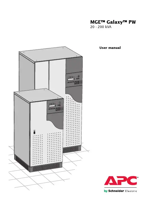
E-51028230XT/BG - 1User manualMGE™ Galaxy™ PW20 - 200 kVA2 - E-51028230XT/BGContents IntroductionGeneral characteristics of MGE™ Galaxy™ PW UPSs (5)System description (6)Different types of MGE™ Galaxy™ PW systems (7)Isolation and protection devices (7)Operation in on-line mode (8)Operation in "eco" mode (10)Operation with an engine generator set (11)Inverter shutdown or overload (12)Output voltage quality and continuity (12)Description of MGE™ Galaxy™ PW cubiclesUPS cubicle (13)Battery cubicle (14)Control panel General (14)Presentation (15)Start-upSystem start-up (17)Start-up of a module (18)ShutdownShutdown of the inverter (19)Shutdown of a rectifier/charger (19)Control-panel displayGeneral organisation (20)Display of messages (20)Measurement system (24)Voltage measurementsi (24)Current measurements (24)Power and frequency measurements (24)Battery measurements (25)Selections and settings (25)Alarms General (28)Maintenance bypass (28)Environment informationSignal reception (29)Signal transmission (29)Logging and time-stampingPresentation of event time-stamping by MGE™ Galaxy™ PW (30)Utilisation via the MGE™ Galaxy™ PW display (30)Utilisation via Teleservice (33)MaintenanceMaintenance configuration (34)Battery maintenance (37)Visual check (37)Functional check (37)Training center (38)OptionsIsolating and voltage matching transformer for the normal and bypass ACSource and the load (39)Harmonics filter and power factor improvement (39)Safety of life and property (39)Empty cubicles (40)Electrical supervision (40)E-51028230XT/BG - 3All products in the MGE™ Galaxy™ PW range are protected by patents. They implement original technology not available tocompetitors of APC by Schneider Electric.To take into account evolving standards and technology, equipment may be modified without notice. Indications concerningtechnical characteristics and dimensions are not binding unless confirmed by APC by Schneider Electric.This document may be copied only with the written consent of APC by Schneider Electric. Authorised copies must be marked"MGE™ Galaxy™ PW User Manual, N° 51028230XT".4 - E-51028230XT/BGIntroduction General characteristics of MGE™ Galaxy™ PW UPSs(1): As per standards ENV 50091-3 / IEC 62040-3.(2): The losses indicated are those produced at full rated load with the battery float charging. They must be taken into account when sizing the ventilation system.(3): Not including any built-in options, such as harmonic filters or a bypass AC-source isolation transformer.E-51028230XT/BG - 5System description(see figure 1)◗ a rectifier/charger module (A) converts 3-phase AC power from the normal AC source supply (1) into DC power for the normal inverter input and float charges or recharges the battery;◗ a battery unit (D) provides backup power for the inverter in the event of a voltage drop or a normal AC source failure;◗ an inverter module (B) converts the DC power supplied by the rectifier/ charger module or the battery unit into 3-phase AC power for the load;◗ a static bypass module (C) ensures the instantaneous transfer of the load to the bypass AC source input in the event of an inverter shutdown (initiated by the user or by a protective device) or a sudden overload;◗ a maintenance bypass isolates the UPS for maintenance and transfers the load to bypass AC source input without interrupting the supply of power. The maintenance bypass is made up of three manual switches (Q3BP, Q4S and Q5N).Note◗ the normal AC input and the bypass AC input have different functions and, depending on the installation, may be protected differently upstream and/or come from different sources.◗ frequency converters are available without backup batteries;◗ the static bypass line and the maintenance bypass line do not exist in installations where the load frequency and the bypass AC source frequency are different (for example in frequency converters);◗ when increased power is required, several MGE™ Galaxy™ PW units may be connected in parallel. In this configuration, an "isolation" function is added for the UPS system as a whole for maintenance purposes, without interrupting the supply of power to the load.Introduction (cont.)The system may also include :◗ an isolating transformer on bypassAC input;◗ a passive harmonic filter (FAH) onthe normal AC input;◗ an active harmonic conditioner on thenormal AC input;◗ different remote control, indicationand display systems.Schematic diagram of the MGE™ Galaxy™ PW systemFig. 16 - E-51028230XT/BGDifferent types of MGE™ Galaxy™ PW systems Frequency converter without battery backup powerParallel UPS systemFig. 2Single-UPS unitFig. 3Frequency converter with battery backup power Fig. 4See figure 5 showing two parallel-connected (redundant) UPS units.A static bypass (C) does not exist inconfigurations.When increased power is required (twoto four parallel units), an externalbypass must be added (see figure 6).Isolation and protectiondevices(See figure 1 on previous page):◗ Q1 (switch):isolation of the rectifier/charger (A)from the normal AC source (1);rectifier/charger (A) start-up;◗ QF1 (circuit breaker):battery (D) protection and isolation;◗ Q5N (switch):isolation of the UPS (B) from theload;◗ Q4S (switch):◗isolation of the static bypass (C) fromthe bypass AC source (2);◗ Q3BP (switch):bypass switch for maintenance;◗ FUE (fuses):protection of the rectifier/charger (A)from the normal AC source;◗ FUS (fuses):protection of the inverter (B) from theload.Note:◗ switch Q3BP does not exist onparallel UPS systems constituted toincrease available power;◗ the "Q3BP" and "Q4S" switches donot exist on frequency converters;◗ circuit breaker QF1 does not exist oninstallations without batteries.External bypass for parallelUPSs and the hot-swapoptionSee figure 6.◗ Q5N (switch): isolation of theinverters of all the parallel UPSsystems from the load;◗ Q4S (switch): isolation of the staticbypasses (C) on each parallel unitfrom the bypass AC source (2);◗ Q3BP (switch): bypass switch formaintenance.Fig. 6Fig. 5Introduction (cont.)E-51028230XT/BG - 78 - E-51028230XT/BGIntroduction (cont.)Operation in on-line modeNormal operationNormal AC source power is available (see figure 7).◗ lights 1 ,4 and 5 shine green on the control panel;◗ the power necessary for the load is provided by the normal AC source (1)through the rectifier/charger (A) and the inverter (B);◗ the rectifier/charger (A) also supplies the power to float charge and recharge the battery if any.The rectifier/charger output voltage (DC) is regulated to supply:the float-charging or the recharging voltage for vented lead-acid or Ni/Cd batteries,◗ a single charge voltage for sealed lead-acid batteries.The voltages depend on the number of battery cells and the batterymanufacturer. Factory set, they may also be adjusted by after-sales support technicians.An electronic board continuouslymeasures the battery temperature and automatically adjusts the voltages.Note:In parallel MGE™ Galaxy™ PWsystems, the power drawn by the load is equally shared between the differentunits.Operation with the normal AC source downSee figure 8.In the event of a normal AC source failure or voltage outside specifiedtolerances of ±10% in amplitude (±15%optionally), the rectifier/charger (A)stops and the battery (D) supplies the necessary backup power to the load via the inverter (B). The battery, float-connected between the rectifier/charger and the inverter, discharges during this operating mode.Lights 2 ,4 and 5 shine green.The user is warned of battery operation by the slow beeping of the buzzer 6(see figure 19) and the message "LOAD PROTECTED, BATTERY DISCHARGING", followed by theremaining backup time and the percent load.This information is also available via volt-free changeover contacts for remote control devices.Note:In the event of a normal AC source failure, frequency converters without a battery shut down and the load is nolonger supplied.Battery timeThe available battery time during a normal AC source outage depends on the:◗ rated capacity of the battery;◗ power consumed by the load;◗ temperature of the battery;◗ age of the battery.The specified battery time corresponds to a minimum duration at full rated load.The actual backup time can therefore be greater if the system operates below its full rated load during the normal AC source outage. Operation on battery power can be extended beyond the specified time by reducing the load power consumption (by disconnecting non-critical loads).A "low battery" warning signal is sent via volt-free changeover contacts for remote control devices when thebattery voltage reaches a level slightly above the minimum level. This signal warns the user of the imminent end of battery power. On the device itself, the buzzer beeps rapidly.The message "LOW-BATTERYSHUTDOWN WARNING" is displayed,followed by the remaining backup time and the percent load. Light 2 turns red and flashes.Battery power stops when the voltage supplied by the battery reaches the minimum threshold (335 V). This results in inverter shutdown andtransfer of the load without interruption to the bypass AC source. Light 2shines red (not flashing). The message "LOAD NOT PROTECTED, ON-LINE MODE" is displayed and the buzzer sounds continuously.If the bypass AC source also fails, the load is no longer supplied. The inverter automatically shuts down when the time on battery power exceeds three times the specified backup time.Note:The "low battery shutdown" warning signal can be sent with an adjustable time delay prior to the effective end of battery power.Fig. 7Fig. 8E-51028230XT/BG - 9Operation with the normal AC source restoredSee figure 9.When normal AC source power (1) is restored or its voltage returns to within specified tolerances, the system automatically returns to its normal operating mode described above (on the condition it did not reach the end of battery power). If the end of battery power was reached (with the resulting inverter shutdown), the rectifier/charger (A) restarts automatically, but theinverter (B) must be restarted manually.The rectifier/charger recharges the battery (D) which was dischargedduring the mains outage. During battery charging, light 2 flashes green.The message "BATTERY CHARGING"is displayed, together with the value of the recharging current and battery voltage.The battery charge cycle takes place in two steps (see figure 10):◗ step 1: the battery is recharged at a constant current limited to 0.1C10 (i.e.1/10th of the battery capacity specified for a 10 hour discharge). The DC voltage increases with the battery charge until the charge level is reached;◗ step 2: the battery is recharged at constant voltage equal to the charge level (maximum value 463 V).The charging current graduallydecreases until reaching a specified low value (floating current).For vented lead-acid batteries, the rectifier/charger supplies the charging voltage for 0 to 255 hours (parameter defined by the after-sales support department) and then the floatingvoltage. For sealed lead-acid batteries,the charging and floating voltages are the same.Note 1:If the normal AC source failure isshorter than 0 to 255 seconds (default value = 30 seconds) (parameter defined by after-sales supportdepartment), the charger automatically supplies the floating voltage given the low battery discharge.Note 2:In frequency converters without battery power, the return of normal AC source power results in the automatic restart of the rectifier/charger and the inverter.Fig. 9Fig. 10Battery charge cycleIntroduction (cont.)Introduction (cont.)Operation with bypass AC source restored◗ no battery discharge (see figure 11). When bypass AC source power supply (2) is restored or returns to within specified tolerances, the load is transferred back to the static bypass (C), without an interruption in the supply of power.Note: this operating mode does not depend on the status of the normal AC source, which may be within or outside the specified tolerances.◗ after battery discharge (see figure 12).Operation of the rectifier/charger (A) with the battery (D) is identical to that presented in the section on on-line mode operation above.Forced transfer and return transfer◗ forced transfer. When the load is supplied via the static bypass (C), it may be transferred to the inverter (B) by pressing pushbutton 20 (see figure 19 in the "control panel" section).The message "FORCED TRANSFER TO INVERTER REQUESTED, POWER TO LOAD MAY BE INTERRUPTED" is displayed. Confirmation by pressing pushbutton 12force transfer. The message "LOAD FORCED TO INVERTER, ECO MODE" is displayed. Whatever the status of the bypass AC source, a return to normal operation in "ECO" mode is possible only through a forced return transfer to the static bypass (C).◗ forced disconnection: as the load is supplied by the inverter (B), it can be transferred to the bypass AC source (M2) via the static bypass (C) by pressing the pushbutton 20 . The message "FORCED TRANSFER TOM2 REQUESTED, POWER TO LOAD MAY BE INTERRUPTED" is then displayed. Confirmation by pressing pushbutton 12disconnection.Note:There are two possibilities: the bypass AC source is within tolerances or outside tolerances. In the first case, the UPS in "ECO" mode returns to normal operation.In the second case, the transfer will take place with a power cut to the load if the bypass AC source is present, or the load will cease to be supplied if it is absent. In both cases, the display reads "LOAD NOT PROTECTED, ECO MODE".Caution:Return to normal operation of the installation in the "ECO" mode is possible only after the bypass AC source has returned to within specified tolerances.Operation in "ECO" modeNormal operationSee figure 11.The power required by the load is supplied by the bypass AC source (2), via the static bypass (C). The rectifier/ charger (A) supplies the power required to float charge and recharge the battery (D).Lights 1 , 3 and 5 shine green and light 4 flashes green. The message "LOAD PROTECTED, ECO MODE" is displayed.Operation with the bypass AC source outside tolerancesWhatever the status of the normal AC source, operation of the rectifier/ charger (A) with the battery (D) is identical to that presented in the section on on-line mode operation above. When bypass AC source (2) characteristics are outside tolerances (voltage: ±10%; frequency as per personalisation; phase sync with inverter ±3°), the load is supplied via the inverter (B).From then on, the minimum operating time on the inverter (B) is 2 minuteseven if the bypass AC source returns to within specified tolerances. Refer to figure 7 in the general appendix if the normal AC source is present, and to figure 8 if it is absent. After this 2 minute period, the load is immediately transferred to the bypass AC source when the latter returns to within specified tolerances.Note:The maximum transfer time of the load from the static bypass (C) to the inverter (B) is 15 ms.Fig. 12Fig. 1110 - E-51028230XT/BGParallel UPSs with redundancy◗ the shutdown of one UPS unit is ofno consequence for the load. Theothers each take up an equal amount of load power and the load continues to be supplied normally;Unit shutdown results in the following on the control panel:lights 4 and 5 go off,activation of the buzzer (continuous beep),the message "LOAD NOTPROTECTED, PARALLEL ON-LINE MODE" is displayed;◗ in the event of an overload, the system only loses its redundancy as long as the overload is less than the total rated power of the functioning units. If the overload is greater, the operating mode is that previously described for systems without redundancy.Frequency converters◗ in the event of a shutdown, the loadis no longer supplied with power;◗ in the event of a major transient overload (greater than 1.65 In), the inverter will current limit to 165% of their rated current for 1 second before stopping;◗ in the event of a smaller but prolonged overload, the inverterrespects the same overload curve as the single inverter and shuts down;◗ in all three of the above cases,inverter shutdown results in the following:lights 4 and 5 go off,◗ activation of the buzzer (continuous beep),the message "LOAD NOTPROTECTED, ON-LINE MODE" is displayed.Inverter shutdown or overloadSee figure 13 for devices orinstallations operating in on-line mode with a bypass AC source.If the conditions are not satisfied, the inverter will current limit to 165% of its rated current for 1 second before stopping;◗ in the event of a small but extended overload (i.e. a continuous level of power exceeding the full rated load),the inverter will continue to supply power for a period depending on the magnitude of the overload (10 minutes for a 125% overload, 1 minute for a 150% overload). See the overload curve in figure 14;◗ in all three of the above cases,inverter shutdown and supply of the load via the bypass AC source results in the following on the control panel: light 4 goes off,◗ activation of the buzzer (continuous beep),◗ light 3 shines green,◗ the message "LOAD NOTPROTECTED, ON-LINE MODE" is displayed.Parallel UPSs without redundancyThe shutdown of one inverter results in overload on the other inverters in operation. Two cases may then arise:◗ if the overload on each remaining inverter is > than 1.65 ln, the load is immediately transferred to the bypass AC source;◗ if the overload is less than 1.65 ln,the remaining inverters support the overload (see curve in figure 14), and the load is transferred to the bypass AC source;◗ after this transfer: the light 4 goes off,◗ the buzzer is activated and sounds continuously,◗ the light 3 goes on and turns green, the message "LOAD NOTPROTECTED, PARALLEL ON-LINE MODE" is displayed.Single-UPS unit (on-line or "ECO" mode)◗ in the event of a UPS shutdown(initiated by the user or by an internal protective device), the load isautomatically transferred to the bypass AC source. If transfer conditions are satisfied, transfer takes place instantly,without interruption to the load;Note: transfer conditions are not satisfied when bypass AC source characteristics are outside tolerances (voltage: ±10%; frequency as per personalisation; phase sync with inverter ±3°);◗ in the event of a major transient overload (greater than 1.65 In),immediate transfer takes place asabove, without interruption to the load.The return to the inverter is automatic when the overload disappears if the number of possible returns has not been reached (0 to 255, programmable by personalisation). If this number has been reached, the load continues to be supplied by the bypass AC source. This operating mode allows start-up of load devices causing high inrush currents.This system requires satisfied transfer conditions.Fig. 13Fig. 14Introduction (cont.)Operation with an engine generator setSee figure 15 below.If a stand-by generator is included in the installation, it is generally started automatically in the event of a normal AC source failure and connected to the main low voltage switchboard. It is disconnected when normal AC source power is restored.With such a system, the requiredbattery time may be reduced to the time necessary for starting and bringing on line the stand-by generator. The battery (D) supplies power to the inverter (B)during the transfers:◗ normal AC source to the generator;◗ generator to the normal AC source.The transfer sequences described above (normal AC source ➜ battery,battery ➜ generator, generator ➜battery, and battery ➜ normal ACsource) are fully automatic. They in no way affect the load and require no manual operation by the user.Note:To avoid load surges on the generator,the rectifier/charger is started with a 10second maximum current consumption walk-in (lasting 3 to 10 seconds,depending on the percent load).To avoid overloading an undersized engine generator set, it is possible to set a maximum power level drawn by the normal AC input. Any additional power required is supplied by thebattery. This modification can be made on site by an APC by Schneider Electric technician.Fig. 15Example of an installation with an engine generator setIntroduction (cont.)Output voltage quality and continuityThe output voltage is stable inamplitude and frequency and is free of interruptions or transients outside specified tolerances, irrespective of normal AC source or load disturbances (outages, load step changes, etc.).Steady state voltage regulationFor stable or slowly varying loadconditions, the inverter output voltage is regulated to within ±0.5% in amplitude.The frequency of the output voltage can theoretically be regulated to within 0.1% of the rated value, however the output frequency range may beintentionally extended to a maximum of ±2 Hz so that the inverter can remain synchronised with the bypass AC source and its inherent frequency fluctuations, thus enabling transfer of the load to the bypass line at any time.Note:The output frequency range can be personalised and if necessary modified on the customer site by a qualified APC by Schneider Electric supporttechnician from ±0.25 Hz to ±2 Hz in 0.25 HZ steps.When the bypass AC source voltage moves outside this frequency range,the inverter is desynchronised and operates in "free running" mode, with the output frequency regulated to a high level of accuracy by a quartz oscillator.When the bypass AC source frequency returns to within the specifiedtolerances, the inverter is gradually re-synchronised to the bypass line at a rate of 0.5 Hz to 2Hz/s (as per the value personalised by the after-sales support department), thus avoiding exposing the load to sudden frequency variations.Transient voltage regulationThe inverter output voltage is not notably affected by instantaneousmajor variations in load characteristics.This is made possible by the PWM (Pulse Width Modulation) chopping technique and the microprocessor-based regulation system that instantly compensates for any variation. In particular, the inverter output voltage remains within +/- 2% of the rated voltage for load step changes of 0 to 100% or of 100 to 0%.Description of MGE™ Galaxy™ PW cubiclesFig. 16Control panelBattery cubicleFigure 17 shows an example of component layout in a battery cubicle or a battery circuit-breaker enclosure. Legend for figure 17:1 - battery isolation and protection circuit breaker QF1,2 - battery cells.Fig. 17GeneralThe control panel onMGE™ Galaxy™ PW UPSs comprisesthe basic controls and indicationsrequired to check the general status ofthe system (see figure 19).Located in the upper right part of thecubicle front, the control panel isdesigned to provide an easy and rapidoverview of system status (see figure19 on next page).Interpretation of symbols is very simpleand requires no particular training.The information concerns only thecubicle on which the panel is located.The panel indicates:◗ normal operation (load protected);◗ operation with load on battery power;◗ abnormal situations (operatingproblem);◗ dangerous situations (load notprotected).Note:The information on the bypass ACsource provided below does notconcern frequency converters.Information on batteries does notconcern frequency converters withoutbatteries.Fig. 18"Inverter" light 4◗ light off: inverter OFF;◗ light flashing green: inverter starting,inverter ON but not connected to the load;◗ light shines green: normal inverter operation;◗ light shines red: inverter fault, the stored alarm indicates one or several of the following faults:◗ inverter shutdown due to inverter output voltage outside specified tolerances,protection fuse at the inverter output (FUS) blown,abnormally high inverter-output transformer temperature,abnormally high inverter temperature, output-voltage fault (amplitude or phase) (parallel UPSs),◗ fault, non-calibration or non-personalisation of the electronic control board for the inverter,fault on the electronic power-supply board."Load" light 5◗ light off: load not supplied;◗ light shines green: load supplied viathe inverter or the bypass AC source (via the static bypass).PresentationSee figure 19."Rectifier/charger" light 1◗ light off: rectifier/charger OFF;◗ light shines green: rectifier/chargerON;◗ light shines red: rectifier/charger fault,the stored alarm indicates one or several of the following faults:◗ input switch Q1 open,◗ protection fuse at the rectifier/charger input (FUE) blown,◗ abnormally high internal rectifier/charger temperature,abnormally high battery charge current,◗ abnormally high battery voltage,◗ fault, non-calibration or non-personalisation of the electronic control board for the rectifier/charger,fault on the electronic power-supply board."Battery light" 2◗ light off: battery float charging;◗ light flashing green: batteryrecharging;◗ light shines green: load on battery power;◗ light flashing red: low-battery shutdown warning;◗ light shines red: battery at end of backup time and circuit breaker QF1open, or battery fault."Static-bypass" light 3◗ light off: bypass AC source withinspecified tolerances and static bypass open;◗ light shines green: static bypass closed;◗ light shines red: the stored alarmindicates one or several of the following faults:◗ bypass AC source voltage orfrequency outside specified tolerances, static-bypass fault,◗ abnormally high internal static-bypass temperature,static-bypass ventilation fault, power-supply fault for the static-bypass control function,◗ fault on the electronic board controlling the transfer function,◗ non-calibration or non-personalisation of the electronic control board for the inverter,fault on the electronic power-supply board,fault on monitoring the "inverter ready" response channels (parallel UPS system).Buzzer 6The buzzer sounds in the following situations:◗ load supplied by the bypass AC source;◗ load on battery;◗ operating problems.It sounds slowly and discontinuously for a minor problem or when the inverter is on battery power.When the alarm "LOW BATTERY SHUTDOWN" is activated, the buzzer sounds more rapidly. Finally, if the inverter shuts down, the beep is loud and continuous. The buzzer may be reset by pressing a button. If the buzzer is reset, a higher level alarm will set it off again."Full-shutdown" button 7Pressing this button shuts down the entire UPS (shutdown of the inverter and rectifier/charger, opening of the battery circuit breaker and activation of a relay contact on the Media Contacts 11 board)."Inverter ON" button 8This button is used to start the inverter locally."Inverter OFF" button 9This button turns the inverter off locally.Fig. 19Control panel (cont.)。
MGE Comet 系列UPS培训资料一、题纲a、UPS原理b、UPS保养c、日常注意事项d、应急处理e、常用电话二、UPS原理UPS( Uninterruptible Power System ),即不间断电源,是一种含有储能装置,以逆变器为主要组成部分的恒压恒频的不间断电源。
作为通讯、网络、制造业等各行各业广泛使用的电源系统,其不间断功能、净化功能和保障数据与生产安全的作用显得越来越重要,当市电中断( 事故停电 )时, UPS 立即将电池的电能,通过逆变转换的方法向负载继续供应交流电,使负载维持正常工作并保护负载软、硬件不受损坏。
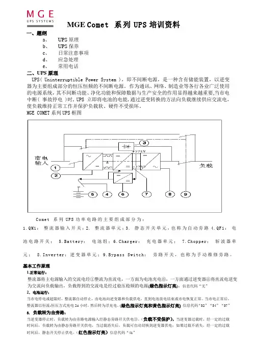
MGE COMET系列UPS框图C o me t 系列UP S功率电路的主要组成部分为:1.QM1:整流器输入开关;2. 整流器单元;3. 静态开关单元,也称为自动旁路4.QF1:电池电路开关;5.Battery:电池组;6.Charger:充电器单元;7.Chopper:斩波器单元;8.Inverter:逆变器单元;9.Bypass Switch:旁路开关,也称为手动维修旁路。
基本工作原理1.正常运行:整流器将主电源输入的交流电经①整流为直流电,一方面为电池充电⑥,一方面通过逆变器⑧将直流电逆变为交流向负载输出,负载得到的交流电是经过稳压稳频的电源(绿色指示灯亮)。
信息代码“无”2.电池运行:当市电停电或超限时,整流器自动停止,由电池向逆变器和负载供电,直到电池放电结束或市电恢复正常。
当市电正常后,整流器以恒流-恒压方式充电24小时,然后转为浮充电。
(绿色指示灯亮和黃色指示灯亮)信息代码“32”“34”“37”3.负载转为由旁路:当逆变器停止时,负载转为由旁路电源输入经静态旁路开关供电③。
(负载不受保护),当逆变器过载时,经一定的过载时间后,负载转为由静态旁路开关供电,当过载消失后,负载可自动切换到逆变器供电;如果过载不消失,经一定的过载时间后,静态开关停止供电。
ups基本知识培训目录一、课程简介 (2)1.1 培训目标 (2)1.2 培训对象 (3)1.3 课程安排 (3)二、UPS基础知识 (4)2.1 UPS的定义与作用 (5)2.2 UPS的类型与结构 (6)2.3 UPS的工作原理 (7)三、UPS基本功能与特点 (8)3.1 电源保护功能 (10)3.2 能量转换功能 (11)3.3 过载保护功能 (12)3.4 电压调节功能 (13)四、UPS安装与调试 (14)4.1 硬件安装 (16)4.2 系统调试 (16)4.3 故障排查 (17)五、UPS日常维护与保养 (17)5.1 定期检查 (18)5.2 维护技巧 (20)5.3 保养周期 (21)六、UPS故障分析及处理 (21)6.1 故障现象描述 (22)6.2 故障原因分析 (23)6.3 故障处理步骤 (24)七、UPS的相关技术 (24)八、UPS在重要领域的应用 (25)8.1 企业数据中心 (26)8.2 医疗机构 (28)8.3 工业生产 (28)九、实操训练 (30)9.1 硬件操作 (30)9.2 尝试故障处理 (31)十、考核与总结 (31)10.1 课堂教学考核 (32)10.2 实操考核 (33)10.3 培训总结 (34)一、课程简介本“基本知识培训”课程旨在为学员提供全面深入的系统的基础知识和操作技能。
课程围绕的核心功能、工作原理、适用范围及在实际应用中的重要性展开,帮助学员了解在提高电力系统可靠性、保障关键设备稳定运行方面的重要作用。
本课程适用于电力系统维护人员、数据中心工程师、从业人员以及所有对技术感兴趣的学员。
通过学习,学员不仅可以提升个人专业技能,也为企业提高电力系统可靠性、保障业务连续性提供有力支持。
1.1 培训目标本培训旨在为参与者提供系统的基本理论知识与实际操作技能,确保每位完成培训的人员能够全面理解的工作原理、维护方法及其在电力保障中的重要作用。
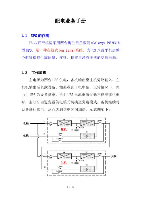
配电业务手册1.1 UPS的作用T3八百平机房采用两台梅兰日兰银河(Galaxy) PW 9315型UPS,是一种在线式(on line)系统,为 T3八百平机房整个航管楼提供高质量、连续、稳定且没有干扰的交流电源。
1.2 工作原理主电源为两台UPS供电,备机输出至主机旁路输入,主机机输出至负载设备。
如果遇到市电中断,正常情况下,先由主UPS为设备供电,当主UPS电池电压过低不能继续供电时,主UPS由逆变器供电模式切换至旁路模式,备机继续对设备进行供电,从而达到供电时间加倍。
示意图如下:备机主机1.3 系统说明1.3.1 整流/充电器模块(A)将电源1提供的三相交流电变换成直流电,用于逆变器的正常输入和给电池进行浮充电或强充电;1.3.2 电池单元(D)在电源1超限或停电情况的下为逆变器提供后备电源;1.3.3 逆变器模块(B)将整流/充电器或电池单元提供的直流电变换成三相交流电供给负载;1.3.4 静态旁路模块(C)保证在逆变器停机(由用户操作或保护装置引起)或突然过载的同时,将负载切换到电源2;1.3.5 维修旁路用于维修时将UPS进行隔离,并将负载无间断地切换到电源2的旁路输入,维修旁路由三个手动开关(Q3BP、Q4S和Q5N)组成。
1.4、开关及保险功能介绍电源1负载电源21.4.1 Q1(开关)●将整流/充电器(A)与电源1隔离;●整流/充电器(A)启动;1.4.2 QF1(断路器)●电池(D)保护和隔离;1.4.3 Q5N(开关)●将UPS的逆变器或频率变换器(B)与负载隔离;1.4.4Q4S(开关)●将静态开关(C)与电源2隔离;1.4.5Q3BP(开关)●手动维修旁路开关;1.4.6FUE(保险)●保护整流/充电器(A)不受电源1的影响;1.4.7FUS(保险)●保护逆变器(B)不受负载的影响。
注:1.在频率变换器或在并联增容UPS系统中没有Q3BP开关;2.在没有电池的系统中没有QF1断路器。