MoldWizard模具设计教程
- 格式:pdf
- 大小:4.67 MB
- 文档页数:34

![任务1注塑模moldwizard设计基本操作[13页]](https://uimg.taocdn.com/0631a3a5f46527d3250ce0ab.webp)

第一章 UG模具设计概述1.1 MoldWizard简介UG软件中有一个专门用于注塑模具设计的模块——MoldWizard。
在UG环境下可通过三条途径进入MoldWizard模块。
●UG主界面上已有【注塑模向导】。
●在零件造型结束后,单击【开始】——【应用所有模块】——【注塑模向导】。
●在UG主界面菜单栏的空白处单击右键,打开如下菜单:选中【注塑模向导】。
【注塑模向导】的工具栏如下:1.2 UG模具设计一般过程第二章第二章模具设计项目的初始化2.1 装载塑件(Load Products)【注塑模向导】——【项目初始化】——【打开部件文件】(选择目标塑件)——【项目初始化】●【设置项目路径和名称】单击“设置项目路径和名称”按钮,将打开“选择项目路径和名称”对话框,通过浏览目录来设置所设计的模具结构的存储位置和名称。
注塑模向导自动将文件放置在项目初始化对话框里设置的项目路径(Project Path)的目录下。
要确认该路径的确是存储你模具设计项目的位置。
如果要改变该项目路径和名称,请点击项目初始化(Project Initialize)对话框里的设置项目路径和名称(Set Project Path and Name)按钮,来显示设置项目路径和名称(Set Project Path and Name)对话框。
然后你可以选择或创建一个目录来存储你的模具设计项目的文件。
在“项目路径”和“项目名”文本框中分别输入项目路径和项目名称,所设计的项目将以设定的名称和路径保存。
如果所设置的文件路径不存在,系统将创建该文件路径。
一般情况下,项目名称的长度限制在10个字符以内,系统默认的项目名称为所选产品零件的文件名。
●【重命名对话框】重命名对话框用于改变项目文件默认的命名规则,使用户可以重新设置项目中的文件名称。
打开重命名对话框的开关后,左键单击啊“确定”按钮或“enter”键,打开如下对话框。
【部件名管理】——【下一个数】——输入26(数字用于区分文件,各家有各家的命名规则)——【设置所有名称】(重命名生效)片刻,又弹出【部件名管理】——【下一个数】——输入51——【设置所有名称】(另一个塑件部件名重命名生效)●【部件材料】(设置或重新设置材料);部件材料是指所设计的产品使用何种材料。

注塑模设计教程·补充教程:注塑模具设计03标准模架MoldWizard有电子表格驱动的标准件库,这些库可被客户化,还可以依据用户的需要来扩展这些库以满足特殊的需求。
MW模块的标准件库中包含有模架库和标准件。
如何合理的选用模架及标准件,这是每个设计者必须面对的问题,因此需要先了解模架及标准件的相关知识。
标准模架分为两大类:大型模架和中小型模架。
两种模架的主要区别在于适用范围。
中小型模架的尺寸为B×L≤500mm×900mm,而大型模架的尺寸B×L为630mm×630mm~1250mm×20XXmm。
UG7【模架设计】对话框如图1所示。
图1在目录下拉菜单可以选择UG自带的标准模架供应厂商。
【目录】栏下拉列表显示被 Mold Wizard 选录的生产制造标准模架和标准件,包括四家世界著名公司的名称:美国DME 公司、德国 HASCO 公司、日本 FUTABA 公司、香港 LKM 公司。
选择其中一家公司牌号,【模架管理】对话框就显示该牌号系列标准模架。
【UNIVERSAL】选项是按实际需要自己配置模架模板尺寸。
日本FUTABA 公司的模架结构形式精炼,而且种类也多,标准模架如何选用就用 FUTABA 牌号模架进行介绍。
在【目录】栏下拉列表选择“FUTABA_S”,类型中选择“SB”, 如表1所示。
图2下面以FUTABA模架管理对话框为例:1)【目录】FUTABA模架分FUTABA_S、FUTABA_DE、FUTABA_FG、FUTABA_H四个分类,前三个分类又分为小型高强度模架和中小型模架,小型高强度模架用后缀区分。
2)【类型】显示指定供应商提供的标准模架类型号,每一个代号表示一种模架结构。
见表1所示为FUTABA的各系列。
3)示图区:显示所选模架的结构示意图、导柱放置位置和推杆与推板固定形式示意图。
4)模板尺寸显示窗:显示所选模架的系列标准模板在X-Y平面投影的有效尺寸,该窗口用来选择模板大小,系统根据模具的布局确定最适合的尺寸作为默认选择。

UG/ MoldWizard使用手册引言MoldWizard是什么?MoldWizard是针对注塑模具设计的一个过程应用 . 型腔和模架库的设计统一到一连接的过程中 .MoldWizard 为建立型腔 , 型芯 , 滑块 , 提升装置和嵌件的高级建模工具方便地提供快速 , 相关的 , 三维实体结果 .在 MoldWizard中 , 模具相关概念的知识 _ 型芯和型腔, 模架库和标准件_是用如 UG/WAVE和 Unigraphics主模型的强大技术组合在一起 .优点 :●过程自动化●易于使用●完全的相关性 .主要程序 :●准备○装载产品模型/模具坐标系/计算收缩率 /设定毛坯尺寸 /中心布局 .●型芯和型腔○搜索分模线 /建立分模面 /修补孔/抽取区域 /建立型芯和型腔.●模架库和标准件用户介面 User Interface○引导你通过为完成你的模具设计的一个合理的行进步 .装载产品连接部件到模具设计项目并构造一初始的模具装配 .模具装配模板树注 :用户可以建立或修改模具装配模板树. 并通过在\ moldwizard\mold_defaults.def 中的下列变量规定英制和米制单位模具装配模板树的路径指定 :MW_MoldAssemblyMetricTopTemplate: \users\moldtree\anytop.prtMW_MoldAssemblyMetricProductTemplate:\users\moldtree\anyprod.prt模具坐标系Mold Csys再定位产品模型的链接拷贝在收缩的部件中 . MoldWizard假定 WCS正 ZC方向为顶出方向 , XC-YC平面是模具装配的分模平面 .再定位WCS:选择Mold CSYS计算收缩率Shrinkage建立一收缩部件 ,在产品模型与收缩部件间的相关联关系使得在模型上的工作继续能更新收缩部件.收缩是作用到收缩部件上的一个比例因子去补偿当冷却时部件的收缩.注:选择计算收缩率( shrinkage) 图标自动地导航装配和设置收缩部件为工作部件部件.设定毛坯尺寸Insert Box定义一个将被用于定义型腔和型芯毛坯尺寸的容积.设定毛坯尺寸功能通过测量部件和建议一可被调整的适当尺寸建立毛坯块 .布局Layout用于在模具装配结构中添加 , 移去或重定位型腔 ,在这个过程中产品子装配树被操纵. 注 :布局功能主要用于多型腔模具工具分模分模是基于一塑料的部件模型建立型芯与型腔的过程. 当你选择分模 (Parting) 图标时 , 显示部件将自动地改变到当前分模部件 .注 :●新的分模功能○自动搜索分模线○自动寻找补丁环○自动打补丁○产品设计顾问[上一模架库标准件注 :标 准 件 包 括 顶 杆 , 型 芯 销 , 定 位 环 和 注 口 , 螺 钉, 锁 块 , 导 向 柱 …注 : __顶杆后处理用分模面修剪顶杆调整顶杆长度Misumi 标准○对每种标准件许多的更改许多条件约束 , 如D/2<DKC<H/2设计步骤 :○块形状由 Mold Tools来实现○设置块中心线的方向○加入座的标准件○重定位标准件○调整块座尺寸○链接块形状到座 , 并加到目标体上○必要时调整模架尺寸.嵌件例子 :浇口●平衡式 / 非平衡式○位置 : 型芯侧 /型腔侧○浇口原点○8 种类型浇口有效 .浇口类型 :流道流道设计步骤 :○定义流道路径的引导线○投射引导线到分模面○选择流道截面形状建立流道 .电极设计例建腔Create Pocket 的功能在模板 , 型芯 , 型腔等需要安装标准件的部位建立空腔并留出相应的间隙 . 把标准件作为工具体 , 模架上所有与该标准件相交的零件都会自动地减去该标准件, 并保持其形状和尺寸与之相关.Target+Standard __先选目标体 (模板 , 型芯 , 型腔 ),Ok 或Apply之后 , 再选准件 .Target Body___选择目标体, 所有与之相交的标准件都将作为工具体自动被减掉 .Standard Part___当一个标准件被选中后 , 就把该标准件作为工具体 , 所有与之相交的模板 , 型芯 , 型腔等都将作为目标体自动减去该标准件.参数预设置___在 moldwizard/mold_defaults.def 文件中设置●项目单位●目录路径●文件命名●层和颜色●处理选项。
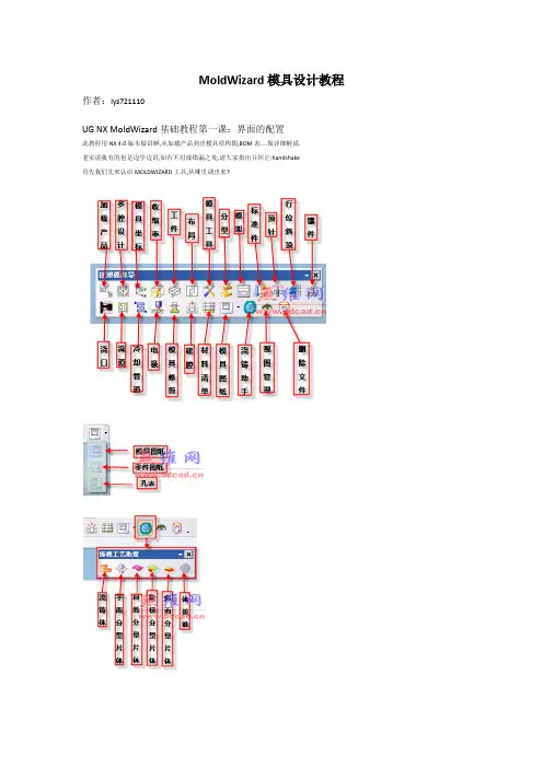
MoldWizard模具设计教程作者:lys721110UG NX MoldWizard基础教程第一课:界面的配置此教程用NX 4.0版本做讲解,从加载产品到出模具结构图,BOM表....做详细解说.老实说我有的也是边学边讲,如有不对或错漏之处,请大家指出并纠正:handshake首先我们先来认识MOLDWIZARD工具,从哪里调出来?调出MOLDWIZARD工具条的几种方法,请看视频一:项目初始化1:选择MOLDWIZARD工具条上的加载产品(项目初始化)图标2:浏览产品目录并选择产品3:按OK进入项目初始化对话框按配置__再按编辑注册器_会自动进入MOLDWIZARD装配的注册文件在这里你可添加自己的模具装配,这个有机会以后再讲:初始对话框详解如果选上了重命名对话框则按确定后会进入部件名管理对话框此处可按个人或公司的命名规则对模具组件重命名加载产品_初始化视频第一课到此为止第二课之前先熟悉下UG_MOLDWIZARD装配结构TOP: 模具最顶层装配,所有模具组件都在TOP下面VAR: 部件包含模架和标准件里用到的表达式。
标准件里用到的标准数值如螺纹孔径会存储在该部件里COOL: 用来创建冷却管道, 冷却管道的标准件也会默认放在这里.COLL分二部分,分别是SIDE_A(对应前模组件) SIDE_B(对应后模组件) FILL: 用于创建浇道和浇口MISC: 放置没有定义到单独部件的标准件, 如模架上:定位环,锁模块,撑头等.MISC也分二部分:SIDE_A(对应前模组件) SIDE_B(对应后模组件)LAYOUT: 用来放"prod" ,多腔模的LAYOUT有多个分支来安排每一个"prod"PROD: 放置产品,收缩件, 型腔,型芯……,以及顶针等。
多腔模可以使用Prod的阵列,来再利用所有prod下已经作好的子组件。
也可以放置与塑胶产品部件相关的特定部件的标准件组件,如:顶针,镶针,滑块及斜顶等。

SolidWorks模具设计教程SolidWorks是一款非常流行的三维计算机辅助设计(CAD)软件,广泛应用于各个行业的产品设计、模具设计等。
本文将为大家介绍SolidWorks模具设计的教程,帮助初学者了解基本的设计原则和操作步骤。
首先,我们需要了解模具设计的基本原则。
模具设计的目的是为了生产高质量的产品,因此在设计模具时需要考虑以下几个要素:产品形状、材料选择、生产工艺和制造成本。
产品形状:首先要了解产品的形状和尺寸要求,包括产品的外观形状和内部结构。
我们可以通过与产品设计师合作,获取产品的三维模型。
材料选择:根据产品的设计要求和生产工艺,选择适合的模具材料。
常见的模具材料包括钢、铝合金、塑料等。
材料的选择应该考虑到模具的强度、耐磨性、导热性等因素。
生产工艺:了解产品的生产工艺非常重要,因为模具的设计必须符合产品的生产要求。
我们可以与生产工程师合作,了解产品的制造流程和要求。
制造成本:模具的制造成本是一个重要的考虑因素。
在设计模具时,我们要尽量减少材料的浪费,降低制造难度,提高生产效率。
因此,模具的设计应该是简单、合理和经济的。
接下来,我们将介绍SolidWorks模具设计的操作步骤。
1. 创建一个新的零件文件:打开SolidWorks软件,点击“文件”,选择“新建”->“零件”,并选择合适的单位和尺寸。
2.绘制产品的草图:使用绘图工具在零件文件中绘制产品的草图。
可以使用线条、弧线、圆等工具来绘制产品的外观形状和内部结构。
3.添加约束和尺寸:使用约束工具给产品的草图添加必要的约束条件,以保证草图的准确性和稳定性。
同时,使用尺寸工具给草图添加尺寸信息,以便后续的模具设计。
4.创建模具和模具零件:使用拉伸、旋转、剪裁等工具将产品草图转化为具体的模具形状。
根据产品的材料和工艺要求,选择合适的模具材料,设计模具的外壳和内部结构。
5.添加特征和孔口:在模具零件上添加必要的特征和孔口。
例如,添加导向孔口、冷却孔口、强化孔口等,以提高模具的功能和性能。
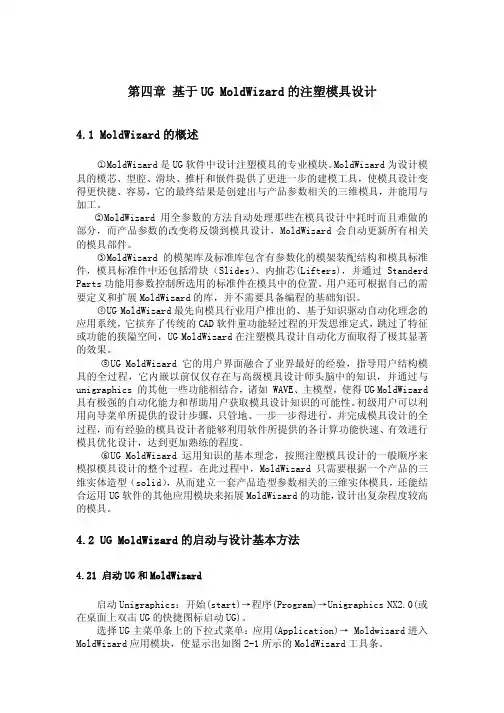
第四章 基于UG MoldWizard的注塑模具设计4.1 MoldWizard的概述○1MoldWizard是UG软件中设计注塑模具的专业模块。
MoldWizard为设计模具的模芯、型腔、滑块、推杆和嵌件提供了更进一步的建模工具,使模具设计变得更快捷、容易,它的最终结果是创建出与产品参数相关的三维模具,并能用与加工。
○2MoldWizard用全参数的方法自动处理那些在模具设计中耗时而且难做的部分,而产品参数的改变将反馈到模具设计,MoldWizard会自动更新所有相关的模具部件。
○3MoldWizard的模架库及标准库包含有参数化的模架装配结构和模具标准件,模具标准件中还包括滑块(Slides)、内抽芯(Lifters),并通过Standerd Parts功能用参数控制所选用的标准件在模具中的位置。
用户还可根据自己的需要定义和扩展MoldWizard的库,并不需要具备编程的基础知识。
○4UG MoldWizard最先向模具行业用户推出的、基于知识驱动自动化理念的应用系统,它摈弃了传统的CAD软件重功能轻过程的开发思维定式,跳过了特征或功能的狭隘空间,UG MoldWizard在注塑模具设计自动化方面取得了极其显著的效果。
○5UG MoldWizard它的用户界面融合了业界最好的经验,指导用户结构模具的全过程,它内嵌以前仅仅存在与高级模具设计师头脑中的知识,并通过与unigraphics 的其他一些功能相结合,诸如 WAVE、主模型,使得UG MoldWizard 具有极强的自动化能力和帮助用户获取模具设计知识的可能性。
初级用户可以利用向导菜单所提供的设计步骤,只管地、一步一步得进行,并完成模具设计的全过程,而有经验的模具设计者能够利用软件所提供的各计算功能快速、有效进行模具优化设计,达到更加熟练的程度。
○6UG MoldWizard运用知识的基本理念,按照注塑模具设计的一般顺序来模拟模具设计的整个过程。
第1章MoldWizard入门【目的】本章将用一个完整的MoldWizard设计过程作为学习MoldWizard的入门。
详细的设计过程及功能介绍将在以后的章节里进一步描述。
【目标】完成本章学习后,将能够:•启动MoldWizard应用模块。
•浏览主目录(Student Home Directory)的文件结构。
•遵循MoldWizard的整个设计项目。
•了解MoldWizard工具栏的含义。
•用MoldWizard的基本原理执行各种设计功能和程序。
【练习】练习1-1启动Unigraphics NX和Moldwziard练习1-2开始模具设计项目练习1-3设定模具坐标系练习1-4定义成型镶件(Work Piece)及多腔模布局(Layout)练习1-5分型(Parting)、定义型芯(Core)和型腔(Cavity)练习1-6加入模架(Mold Base)和标准件(Standard Parts)1.1什么是MoldWizardMoldWizard是Unigraphics NX软件中设计注塑模具的专业模块。
MoldWizard为设计模具的型芯、型腔、滑块、推杆和嵌件提供了更进一步的建模工具,使模具设计变得更快捷、容易,它的最终结果是创建出与产品参数相关的三维模具,并能用于加工。
MoldWizard用全参数的方法自动处理那些在模具设计中耗时而且难做的部分,而产品参数的改变将反馈到模具设计,MoldWizard会自动更新所有相关的模具部件。
MoldWizard的模架库及其标准件库包含有参数化的模架装配结构和模具标准件,模具标准件中还包括滑块(Slides)、内抽芯(Lifters),并可通过Standard Parts功能用参数控制所选用的标准件在模具中的位置。
用户还可根据自己的需要定义和扩展MoldWizard 的库,并不需要具备编程的基础知识。
UG NX2注塑模具设计培训教程21.2学员条件要熟练地使用MoldWizard,必须熟悉模具及其设计过程,并具备Unigraphics NX基础知识及掌握以下Unigraphics NX应用工具。
SOLIDWORKSMold Design Using SOLIDWORKS Dassault Systèmes SolidWorks Corporation175 Wyman StreetWaltham, MA 02451 U.S.A.© 1995-2022, Dassault Systemes SolidWorks Corporation, a Dassault Systèmes SE company, 175 Wyman Street, Waltham, Mass. 02451 USA. All Rights Reserved.The information and the software discussed in this document are subject to change without notice and are not commitments by Dassault Systemes SolidWorks Corporation (DS SolidWorks).No material may be reproduced or transmitted in any form or by any means, electronically or manually, for any purpose without the express written permission of DS SolidWorks.The software discussed in this document is furnished under a license and may be used or copied only in accordance with the terms of the license. All warranties given by DS SolidWorks as to the software and documentation are set forth in the license agreement, and nothing stated in, or implied by, this document or its contents shall be considered or deemed a modification or amendment of any terms, including warranties, in the license agreement.For a full list of the patents, trademarks, and third-party software contained in this release, please go to the Legal Notices in the SOLIDWORKS documentation.Restricted RightsThis clause applies to all acquisitions of Dassault Systèmes Offerings by or for the United States federal government, or by any prime contractor or subcontractor (at any tier) under any contract, grant, cooperative agreement or other activity with the federal government. The software, documentation and any other technical data provided hereunder is commercial in nature and developed solely at private expense. The Software is delivered as "Commercial Computer Software" as defined in DFARS 252.227-7014 (June 1995) or as a "Commercial Item" as defined in FAR 2.101(a) and as such is provided with only such rights as are provided in Dassault Systèmes standard commercial end user license agreement. Technical data is provided with limited rights only as provided in DFAR 252.227-7015 (Nov. 1995) or FAR 52.227-14 (June 1987), whichever is applicable. The terms and conditions of the Dassault Systèmes standard commercial end user license agreement shall pertain to the United States government's use and disclosure of this software, and shall supersede any conflicting contractual terms and conditions. If the DS standard commercial license fails to meet the United States government's needs or is inconsistent in any respect with United States Federal law, the United States government agrees to return this software, unused, to DS. The following additional statement applies only to acquisitions governed by DFARS Subpart 227.4 (October 1988): "Restricted Rights - use, duplication and disclosure by the Government is subject to restrictions as set forth in subparagraph (c)(l)(ii) of the Rights in Technical Data and Computer Software clause at DFARS 252-227-7013 (Oct. 1988)."In the event that you receive a request from any agency of the U.S. Government to provide Software with rights beyond those set forth above, you will notify DS SolidWorks of the scope of the request and DS SolidWorks will have five (5) business days to, in its sole discretion, accept or reject such request. Contractor/ Manufacturer: Dassault Systemes SolidWorks Corporation, 175 Wyman Street, Waltham, Massachusetts 02451 USA.Document Number: PMT2305-ENGContents IntroductionAbout This Course . . . . . . . . . . . . . . . . . . . . . . . . . . . . . . . . . . . . . . . . 2Prerequisites . . . . . . . . . . . . . . . . . . . . . . . . . . . . . . . . . . . . . . . . . . 2Course Design Philosophy . . . . . . . . . . . . . . . . . . . . . . . . . . . . . . . 2Using this Book . . . . . . . . . . . . . . . . . . . . . . . . . . . . . . . . . . . . . . . . . . 2Laboratory Exercises . . . . . . . . . . . . . . . . . . . . . . . . . . . . . . . . . . . 3A Note About Dimensions . . . . . . . . . . . . . . . . . . . . . . . . . . . . . . . 3Conventions Used in this Book . . . . . . . . . . . . . . . . . . . . . . . . . . . 3About the Training Files. . . . . . . . . . . . . . . . . . . . . . . . . . . . . . . . . 3Training Templates. . . . . . . . . . . . . . . . . . . . . . . . . . . . . . . . . . . . . 4Windows. . . . . . . . . . . . . . . . . . . . . . . . . . . . . . . . . . . . . . . . . . . . . . . . 4Use of Color . . . . . . . . . . . . . . . . . . . . . . . . . . . . . . . . . . . . . . . . . . . . . 5Color Schemes . . . . . . . . . . . . . . . . . . . . . . . . . . . . . . . . . . . . . . . . 5SOLIDWORKS Plastics. . . . . . . . . . . . . . . . . . . . . . . . . . . . . . . . . . . . 6More SOLIDWORKS Training Resources. . . . . . . . . . . . . . . . . . . . . . 6Local User Groups . . . . . . . . . . . . . . . . . . . . . . . . . . . . . . . . . . . . . 6 Lesson 1Surface Concepts and Imported GeometryCourse Overview . . . . . . . . . . . . . . . . . . . . . . . . . . . . . . . . . . . . . . . . . 8Surfaces in Mold Design. . . . . . . . . . . . . . . . . . . . . . . . . . . . . . . . . . . . 83D Model Types . . . . . . . . . . . . . . . . . . . . . . . . . . . . . . . . . . . . . . . . . . 9Wireframe Models . . . . . . . . . . . . . . . . . . . . . . . . . . . . . . . . . . . . . 9Surface Models. . . . . . . . . . . . . . . . . . . . . . . . . . . . . . . . . . . . . . . . 9Solid Models. . . . . . . . . . . . . . . . . . . . . . . . . . . . . . . . . . . . . . . . . . 9Geometry vs Topology . . . . . . . . . . . . . . . . . . . . . . . . . . . . . . . . . . . . . 9What is a Solid? . . . . . . . . . . . . . . . . . . . . . . . . . . . . . . . . . . . . . . 11Euler’s Formula . . . . . . . . . . . . . . . . . . . . . . . . . . . . . . . . . . . . . . 11iContents SOLIDWORKSii Behind the Scenes. . . . . . . . . . . . . . . . . . . . . . . . . . . . . . . . . . . . . . . . 12 Adjusting FeatureManager Settings . . . . . . . . . . . . . . . . . . . . . . . 12 Extruded Surface. . . . . . . . . . . . . . . . . . . . . . . . . . . . . . . . . . . . . . 13 Turning on the Surfaces Toolbar . . . . . . . . . . . . . . . . . . . . . . . . . 13 Planar Surface. . . . . . . . . . . . . . . . . . . . . . . . . . . . . . . . . . . . . . . . 14 Trim Surface. . . . . . . . . . . . . . . . . . . . . . . . . . . . . . . . . . . . . . . . . 15 Untrim Surface . . . . . . . . . . . . . . . . . . . . . . . . . . . . . . . . . . . . . . . 17 Face Curves and Mesh Preview . . . . . . . . . . . . . . . . . . . . . . . . . . 17 Surface Types. . . . . . . . . . . . . . . . . . . . . . . . . . . . . . . . . . . . . . . . 18 Four-Sided Surfaces . . . . . . . . . . . . . . . . . . . . . . . . . . . . . . . . . . . 20 Knit Surface . . . . . . . . . . . . . . . . . . . . . . . . . . . . . . . . . . . . . . . . . 21 Gap Control. . . . . . . . . . . . . . . . . . . . . . . . . . . . . . . . . . . . . . . . . . 21 Creating Solids from Surfaces . . . . . . . . . . . . . . . . . . . . . . . . . . . . . . 22 Create Solid. . . . . . . . . . . . . . . . . . . . . . . . . . . . . . . . . . . . . . . . . . 22 Thicken. . . . . . . . . . . . . . . . . . . . . . . . . . . . . . . . . . . . . . . . . . . . . 22 Summary. . . . . . . . . . . . . . . . . . . . . . . . . . . . . . . . . . . . . . . . . . . . 23 Decomposing a Solid into Surfaces . . . . . . . . . . . . . . . . . . . . . . . . . . 23 Delete Face. . . . . . . . . . . . . . . . . . . . . . . . . . . . . . . . . . . . . . . . . . 23 Additional Surface Concepts . . . . . . . . . . . . . . . . . . . . . . . . . . . . . . . 25 Boolean Operations. . . . . . . . . . . . . . . . . . . . . . . . . . . . . . . . . . . . 25 Edges vs. Holes. . . . . . . . . . . . . . . . . . . . . . . . . . . . . . . . . . . . . . . 25 Surfaces Concepts Takeaways . . . . . . . . . . . . . . . . . . . . . . . . . . . . . . 26 Importing and Mold Design . . . . . . . . . . . . . . . . . . . . . . . . . . . . . . . . 26 Modeling Kernels. . . . . . . . . . . . . . . . . . . . . . . . . . . . . . . . . . . . . 26 Contents of a CAD File . . . . . . . . . . . . . . . . . . . . . . . . . . . . . . . . 27 File Formats . . . . . . . . . . . . . . . . . . . . . . . . . . . . . . . . . . . . . . . . . 27 Format Recommendations . . . . . . . . . . . . . . . . . . . . . . . . . . . . . . 28 File Translation. . . . . . . . . . . . . . . . . . . . . . . . . . . . . . . . . . . . . . . . . . 29 Why Do Imports Fail? . . . . . . . . . . . . . . . . . . . . . . . . . . . . . . . . . . . . 29 SOLIDWORKS Import Options. . . . . . . . . . . . . . . . . . . . . . . . . . . . . 30 3D Interconnect for Native File Formats . . . . . . . . . . . . . . . . . . . 30 3D Interconnect for Neutral File Formats. . . . . . . . . . . . . . . . . . . 31 Case Study: Importing a STEP File . . . . . . . . . . . . . . . . . . . . . . . . . . 31 Import Diagnostics . . . . . . . . . . . . . . . . . . . . . . . . . . . . . . . . . . . . 33 Addressing Errors in 3D Interconnect Imports. . . . . . . . . . . . . . . 34 Another Option. . . . . . . . . . . . . . . . . . . . . . . . . . . . . . . . . . . . . . . 35 Comparing Geometry. . . . . . . . . . . . . . . . . . . . . . . . . . . . . . . . . . . . . 37 Addressing Translation Errors . . . . . . . . . . . . . . . . . . . . . . . . . . . . . . 39 Repairing and Editing Imported Geometry . . . . . . . . . . . . . . . . . . . . 39 Check Entity. . . . . . . . . . . . . . . . . . . . . . . . . . . . . . . . . . . . . . . . . 40 Display Curvature. . . . . . . . . . . . . . . . . . . . . . . . . . . . . . . . . . . . . 42 Patching Strategies . . . . . . . . . . . . . . . . . . . . . . . . . . . . . . . . . . . . 43 Filled Surface . . . . . . . . . . . . . . . . . . . . . . . . . . . . . . . . . . . . . . . . 44 Another Strategy. . . . . . . . . . . . . . . . . . . . . . . . . . . . . . . . . . . . . . 46SOLIDWORKS ContentsProcedure for Rebuilding Fillets. . . . . . . . . . . . . . . . . . . . . . . . . . . . . 48Making Copies of Faces. . . . . . . . . . . . . . . . . . . . . . . . . . . . . . . . 48Offset Surface. . . . . . . . . . . . . . . . . . . . . . . . . . . . . . . . . . . . . . . . 48Extend Surface . . . . . . . . . . . . . . . . . . . . . . . . . . . . . . . . . . . . . . . 50Editing Imported Parts . . . . . . . . . . . . . . . . . . . . . . . . . . . . . . . . . 52Delete Hole. . . . . . . . . . . . . . . . . . . . . . . . . . . . . . . . . . . . . . . . . . 53Exercise 1: Import Diagnosis . . . . . . . . . . . . . . . . . . . . . . . . . . . . . . . 55Exercise 2: Using Import Surface and Replace Face . . . . . . . . . . . . . 58 Lesson 2Core and CavityCore and Cavity Mold Design . . . . . . . . . . . . . . . . . . . . . . . . . . . . . . 62Steps in the Mold Design Process. . . . . . . . . . . . . . . . . . . . . . . . . 62Summary of Steps. . . . . . . . . . . . . . . . . . . . . . . . . . . . . . . . . . . . . 64SOLIDWORKS Mold Tools. . . . . . . . . . . . . . . . . . . . . . . . . . . . . . . . 64Case Study: Camera Body . . . . . . . . . . . . . . . . . . . . . . . . . . . . . . . . . 64Mold Analysis Tools. . . . . . . . . . . . . . . . . . . . . . . . . . . . . . . . . . . . . . 65GPU-based Processing . . . . . . . . . . . . . . . . . . . . . . . . . . . . . . . . . 65Analyzing Draft on a Model. . . . . . . . . . . . . . . . . . . . . . . . . . . . . . . . 65What is Draft?. . . . . . . . . . . . . . . . . . . . . . . . . . . . . . . . . . . . . . . . 65Determining the Direction of Pull . . . . . . . . . . . . . . . . . . . . . . . . 66Using the Draft Analysis Tool . . . . . . . . . . . . . . . . . . . . . . . . . . . . . . 66Positive and Negative Draft . . . . . . . . . . . . . . . . . . . . . . . . . . . . . 68Requires Draft. . . . . . . . . . . . . . . . . . . . . . . . . . . . . . . . . . . . . . . . 68Draft Analysis Options . . . . . . . . . . . . . . . . . . . . . . . . . . . . . . . . . . . . 68Gradual Transition . . . . . . . . . . . . . . . . . . . . . . . . . . . . . . . . . . . . 68Face Classification . . . . . . . . . . . . . . . . . . . . . . . . . . . . . . . . . . . . 69Find Steep Faces. . . . . . . . . . . . . . . . . . . . . . . . . . . . . . . . . . . . . . 69Adding Draft. . . . . . . . . . . . . . . . . . . . . . . . . . . . . . . . . . . . . . . . . . . . 70Scaling the Model. . . . . . . . . . . . . . . . . . . . . . . . . . . . . . . . . . . . . . . . 72Establish the Parting Lines. . . . . . . . . . . . . . . . . . . . . . . . . . . . . . . . . 73Parting Lines Options. . . . . . . . . . . . . . . . . . . . . . . . . . . . . . . . . . 73Manual Parting Lines . . . . . . . . . . . . . . . . . . . . . . . . . . . . . . . . . . 75Shut-Off Surfaces . . . . . . . . . . . . . . . . . . . . . . . . . . . . . . . . . . . . . . . . 75Shut-off Surface Patch Types. . . . . . . . . . . . . . . . . . . . . . . . . . . . 75Manual Shut-off Surfaces. . . . . . . . . . . . . . . . . . . . . . . . . . . . . . . 77Creating the Parting Surface. . . . . . . . . . . . . . . . . . . . . . . . . . . . . . . . 77Parting Surfaces Options . . . . . . . . . . . . . . . . . . . . . . . . . . . . . . . 78Smoothing the Parting Surface. . . . . . . . . . . . . . . . . . . . . . . . . . . 80Surface Bodies . . . . . . . . . . . . . . . . . . . . . . . . . . . . . . . . . . . . . . . . . . 82Creating the Mold Tooling . . . . . . . . . . . . . . . . . . . . . . . . . . . . . . . . . 83Tooling Split. . . . . . . . . . . . . . . . . . . . . . . . . . . . . . . . . . . . . . . . . 83Seeing Inside the Mold. . . . . . . . . . . . . . . . . . . . . . . . . . . . . . . . . . . . 85Interlocking the Mold Tooling . . . . . . . . . . . . . . . . . . . . . . . . . . . . . . 86Creating Interlock Surfaces . . . . . . . . . . . . . . . . . . . . . . . . . . . . . 86Creating Part and Assembly Files. . . . . . . . . . . . . . . . . . . . . . . . . . . . 88Completing the Mold . . . . . . . . . . . . . . . . . . . . . . . . . . . . . . . . . . 89iiiContents SOLIDWORKSiv Exercise 3: Casting. . . . . . . . . . . . . . . . . . . . . . . . . . . . . . . . . . . . . . . 90 Exercise 4: Ribbed Part. . . . . . . . . . . . . . . . . . . . . . . . . . . . . . . . . . . . 94 Exercise 5: Dustpan . . . . . . . . . . . . . . . . . . . . . . . . . . . . . . . . . . . . . . 97Lesson 3Side Cores and PinsAdditional Mold Tooling . . . . . . . . . . . . . . . . . . . . . . . . . . . . . . . . . 110Additional Tooling Design Process . . . . . . . . . . . . . . . . . . . . . . 110Case Study: Power Saw Housing . . . . . . . . . . . . . . . . . . . . . . . . . . . 111Thickness Analysis. . . . . . . . . . . . . . . . . . . . . . . . . . . . . . . . . . . 112Detecting Undercuts. . . . . . . . . . . . . . . . . . . . . . . . . . . . . . . . . . 114Undercut Analysis. . . . . . . . . . . . . . . . . . . . . . . . . . . . . . . . . . . . 114Trapped Molding Areas . . . . . . . . . . . . . . . . . . . . . . . . . . . . . . . . . . 116Side Cores. . . . . . . . . . . . . . . . . . . . . . . . . . . . . . . . . . . . . . . . . . . . . 116Core Feature . . . . . . . . . . . . . . . . . . . . . . . . . . . . . . . . . . . . . . . . 116Feature Freeze. . . . . . . . . . . . . . . . . . . . . . . . . . . . . . . . . . . . . . . . . . 117Lifters . . . . . . . . . . . . . . . . . . . . . . . . . . . . . . . . . . . . . . . . . . . . . . . . 120Core Pins. . . . . . . . . . . . . . . . . . . . . . . . . . . . . . . . . . . . . . . . . . . . . . 122Manual Selection Techniques. . . . . . . . . . . . . . . . . . . . . . . . . . . . . . 123Selection Tools. . . . . . . . . . . . . . . . . . . . . . . . . . . . . . . . . . . . . . 123The Message Pane . . . . . . . . . . . . . . . . . . . . . . . . . . . . . . . . . . . 124Case Study: Mixer Base . . . . . . . . . . . . . . . . . . . . . . . . . . . . . . . . . . 124Modifying Shut-Off Surfaces. . . . . . . . . . . . . . . . . . . . . . . . . . . . . . 127Manual Shut-Off Surfaces . . . . . . . . . . . . . . . . . . . . . . . . . . . . . 127Manually Selecting Loops . . . . . . . . . . . . . . . . . . . . . . . . . . . . . 128Completing the Tooling . . . . . . . . . . . . . . . . . . . . . . . . . . . . . . . . . . 133Exercise 6: Towing Mirror. . . . . . . . . . . . . . . . . . . . . . . . . . . . . . . . 134Exercise 7: Completing the Mixer Base. . . . . . . . . . . . . . . . . . . . . . 141Exercise 8: Electrode Design . . . . . . . . . . . . . . . . . . . . . . . . . . . . . . 150 Lesson 4Advanced Parting Line OptionsCase Study: Manual Parting Line. . . . . . . . . . . . . . . . . . . . . . . . . . . 158Using Split Faces . . . . . . . . . . . . . . . . . . . . . . . . . . . . . . . . . . . . 159Using Entities to Split. . . . . . . . . . . . . . . . . . . . . . . . . . . . . . . . . 160Case Study: Splitting a Part . . . . . . . . . . . . . . . . . . . . . . . . . . . . . . . 164Creating Ruled Surfaces. . . . . . . . . . . . . . . . . . . . . . . . . . . . . . . 166Exercise 9: Peeler . . . . . . . . . . . . . . . . . . . . . . . . . . . . . . . . . . . . . . . 169 Lesson 5Creating Custom Surfaces for Mold DesignSurface Modeling for Mold Design . . . . . . . . . . . . . . . . . . . . . . . . . 176Case Study: Drill Bezel. . . . . . . . . . . . . . . . . . . . . . . . . . . . . . . . . . . 177Manual Interlock Surfaces . . . . . . . . . . . . . . . . . . . . . . . . . . . . . 178Using Select Partial Loop. . . . . . . . . . . . . . . . . . . . . . . . . . . . . . 179Ruled Surface Direction . . . . . . . . . . . . . . . . . . . . . . . . . . . . . . . 180Problem Areas. . . . . . . . . . . . . . . . . . . . . . . . . . . . . . . . . . . . . . . 182Creating the Parting Surface. . . . . . . . . . . . . . . . . . . . . . . . . . . . 184Organizing Surfaces . . . . . . . . . . . . . . . . . . . . . . . . . . . . . . . . . . 185SOLIDWORKS ContentsCase Study: Router Bottom . . . . . . . . . . . . . . . . . . . . . . . . . . . . . . . 187Manual Parting Surface Techniques. . . . . . . . . . . . . . . . . . . . . . 190Organizing Manual Shut-off Surfaces . . . . . . . . . . . . . . . . . . . . 193Copying Surfaces . . . . . . . . . . . . . . . . . . . . . . . . . . . . . . . . . . . . 193Exercise 10: Power Strip. . . . . . . . . . . . . . . . . . . . . . . . . . . . . . . . . . 196Exercise 11: Router Top. . . . . . . . . . . . . . . . . . . . . . . . . . . . . . . . . . 200 Lesson 6Advanced Surfacing for Mold DesignSurface Modeling for Mold Design . . . . . . . . . . . . . . . . . . . . . . . . . 208The Mixer. . . . . . . . . . . . . . . . . . . . . . . . . . . . . . . . . . . . . . . . . . . . . 208Case Study: Mixer Rear Housing. . . . . . . . . . . . . . . . . . . . . . . . . . . 209Manual Parting Surface . . . . . . . . . . . . . . . . . . . . . . . . . . . . . . . 212Insert Mold Folders. . . . . . . . . . . . . . . . . . . . . . . . . . . . . . . . . . . 216Case Study: Mixer Handle . . . . . . . . . . . . . . . . . . . . . . . . . . . . . . . . 219Manual Shut-off Surfaces. . . . . . . . . . . . . . . . . . . . . . . . . . . . . . 219No Fill Shut-off Surfaces . . . . . . . . . . . . . . . . . . . . . . . . . . . . . . 221Manual Side Cores . . . . . . . . . . . . . . . . . . . . . . . . . . . . . . . . . . . 228Exercise 12: Mixer Switch . . . . . . . . . . . . . . . . . . . . . . . . . . . . . . . . 231Exercise 13: Fan Bezel. . . . . . . . . . . . . . . . . . . . . . . . . . . . . . . . . . . 236 Lesson 7Alternative Methods for Mold DesignAlternate Methods for Mold Design. . . . . . . . . . . . . . . . . . . . . . . . . 248When to use Alternate Methods . . . . . . . . . . . . . . . . . . . . . . . . . 248Using Combine and Split . . . . . . . . . . . . . . . . . . . . . . . . . . . . . . . . . 248Copying Bodies in Place. . . . . . . . . . . . . . . . . . . . . . . . . . . . . . . 250Creating a Cavity . . . . . . . . . . . . . . . . . . . . . . . . . . . . . . . . . . . . . . . 252Case Study: Cavity . . . . . . . . . . . . . . . . . . . . . . . . . . . . . . . . . . . . . . 252Case Study: Using Surfaces . . . . . . . . . . . . . . . . . . . . . . . . . . . . . . . 255Techniques for Mold Tooling . . . . . . . . . . . . . . . . . . . . . . . . . . . . . . 258Using the Up To Surface Method. . . . . . . . . . . . . . . . . . . . . . . . 258Using the Split Method. . . . . . . . . . . . . . . . . . . . . . . . . . . . . . . . 259Exercise 14: Peeler Using Combine. . . . . . . . . . . . . . . . . . . . . . . . . 261Exercise 15: Handle . . . . . . . . . . . . . . . . . . . . . . . . . . . . . . . . . . . . . 265Exercise 16: Filter. . . . . . . . . . . . . . . . . . . . . . . . . . . . . . . . . . . . . . . 269 Lesson 8Reusable DataReusing Data. . . . . . . . . . . . . . . . . . . . . . . . . . . . . . . . . . . . . . . . . . . 280Library Features . . . . . . . . . . . . . . . . . . . . . . . . . . . . . . . . . . . . . 280Smart Components . . . . . . . . . . . . . . . . . . . . . . . . . . . . . . . . . . . 2803DEXPERIENCE Marketplace . . . . . . . . . . . . . . . . . . . . . . . . . 280Task Pane . . . . . . . . . . . . . . . . . . . . . . . . . . . . . . . . . . . . . . . . . . . . . 281SOLIDWORKS Resources. . . . . . . . . . . . . . . . . . . . . . . . . . . . . . . . 281Design Library . . . . . . . . . . . . . . . . . . . . . . . . . . . . . . . . . . . . . . . . . 282Essentials of Using the Design Library . . . . . . . . . . . . . . . . . . . 283Folder Graphics. . . . . . . . . . . . . . . . . . . . . . . . . . . . . . . . . . . . . . 283Main Directory Structure . . . . . . . . . . . . . . . . . . . . . . . . . . . . . . 284vContents SOLIDWORKSvi File Explorer. . . . . . . . . . . . . . . . . . . . . . . . . . . . . . . . . . . . . . . . . . . 286 Library Features . . . . . . . . . . . . . . . . . . . . . . . . . . . . . . . . . . . . . . . . 287 Two Techniques for Locating. . . . . . . . . . . . . . . . . . . . . . . . . . . 287 Case Study: Create A Library Feature . . . . . . . . . . . . . . . . . . . . . . . 287 Library Feature Characteristics. . . . . . . . . . . . . . . . . . . . . . . . . . 291 Organizing Library Feature Part Dimensions. . . . . . . . . . . . . . . 293 Replacing Dimensions . . . . . . . . . . . . . . . . . . . . . . . . . . . . . . . . 293 Renaming Dimensions . . . . . . . . . . . . . . . . . . . . . . . . . . . . . . . . 293 Sorting Dimensions . . . . . . . . . . . . . . . . . . . . . . . . . . . . . . . . . . 294 Configurations in Library Features. . . . . . . . . . . . . . . . . . . . . . . . . . 297 Case Study: Water Line. . . . . . . . . . . . . . . . . . . . . . . . . . . . . . . . . . . 297 Creating Library Features from Existing Parts. . . . . . . . . . . . . . 301 Smart Components . . . . . . . . . . . . . . . . . . . . . . . . . . . . . . . . . . . . . . 301 Create the Defining Assembly . . . . . . . . . . . . . . . . . . . . . . . . . . 301 Make Smart Component. . . . . . . . . . . . . . . . . . . . . . . . . . . . . . . 304 Inserting the Smart Component . . . . . . . . . . . . . . . . . . . . . . . . . 305 Inserting Smart Features. . . . . . . . . . . . . . . . . . . . . . . . . . . . . . . 305 Exercise 17: Smart Components. . . . . . . . . . . . . . . . . . . . . . . . . . . . 309 Exercise 18: Complete Mold Insert Project . . . . . . . . . . . . . . . . . . . 310 Developing a Plan. . . . . . . . . . . . . . . . . . . . . . . . . . . . . . . . . . . . 311 Modeling Repairs . . . . . . . . . . . . . . . . . . . . . . . . . . . . . . . . . . . . 313 Runners and Gates . . . . . . . . . . . . . . . . . . . . . . . . . . . . . . . . . . . 321 Side Cores. . . . . . . . . . . . . . . . . . . . . . . . . . . . . . . . . . . . . . . . . . 322 Ejector Pins. . . . . . . . . . . . . . . . . . . . . . . . . . . . . . . . . . . . . . . . . 327 Core Pins. . . . . . . . . . . . . . . . . . . . . . . . . . . . . . . . . . . . . . . . . . . 328 Creating Individual Parts . . . . . . . . . . . . . . . . . . . . . . . . . . . . . . 331Lesson 9Completing the Mold BaseCase Study: Mold Base. . . . . . . . . . . . . . . . . . . . . . . . . . . . . . . . . . . 334Organizing the Assembly . . . . . . . . . . . . . . . . . . . . . . . . . . . . . . . . . 336Assembly Structure Editing . . . . . . . . . . . . . . . . . . . . . . . . . . . . 336Modifying the Lifters . . . . . . . . . . . . . . . . . . . . . . . . . . . . . . . . . . . . 341Lifter Motion. . . . . . . . . . . . . . . . . . . . . . . . . . . . . . . . . . . . . . . . . . . 343Ejector Pins. . . . . . . . . . . . . . . . . . . . . . . . . . . . . . . . . . . . . . . . . . . . 346Adding the Bezel . . . . . . . . . . . . . . . . . . . . . . . . . . . . . . . . . . . . 347Cooling the Mold . . . . . . . . . . . . . . . . . . . . . . . . . . . . . . . . . . . . . . . 350Making the Drawing. . . . . . . . . . . . . . . . . . . . . . . . . . . . . . . . . . . . . 356Making Changes. . . . . . . . . . . . . . . . . . . . . . . . . . . . . . . . . . . . . . . . 357Completing the Process . . . . . . . . . . . . . . . . . . . . . . . . . . . . . . . . . . 361。
SolidWorks 模具设计1. 拔模分析为了创建可以实现注塑的模具, 塑料产品必须被设计和拔模正确才能从围绕在周围的模具中顶出。
要对模型产品进行拔模分析,使用拔模分析命令有助于发现拔模和设计的错误。
对前视面进行向上拔模分析。
来看看各分析面的含义:跨立面:是横跨分型线的面。
用户必须把跨立面分割成两块以分开模具的表面。
跨立面可以通过跨立面命令手工处理或者通过单击分型线命令中的分割面选项自动完成。
正陡面:这些表面中包含部分拔模量不够的区域。
如果整个面的拔模量都不够,它将被归类为【需要拔模】。
这些面能在模具中的正侧找到。
负陡面:这些表面包含部分拔模量不够的区域。
这些面能在模具中的负侧找到。
2. 调整收缩率模具上产品型腔部分的加工要略微比从模具中生产出来的塑料件大些。
这样做是为了补偿高温的被顶出的塑料件冷却后的收缩率。
在通过塑料产品创建模具之前,模具设计者需要放大塑料产品来解决收缩率。
不同的材料,收缩率也是不同的,SolidWorks 用比例缩放命令在解决这个问题。
这个零件我们以ABS 材料来做,5%的收缩率。
3. 确定分型线分型线是注塑类塑料产品中型腔与型心曲面中相互接触的边界。
分型线是那些用来分割型心和型腔曲面的边界。
它们也构成了分型面的内部边界。
型腔面(正拔模)是绿色的,型心面(负拔模)是红色的。
任何一条被红色和绿色面共用的边都是分型线边界。
当拔模分析完成后,所有的被绿色和红色边共用的边被自动选中并被添加到分型线列表中。
单击确定。
手动添加分型线:在这个例子中,当分型线命令运行时,分型线边被自动的选中。
因为这是一个简单的分型线边界,这些边界被自动添加到位于分型线PropertyManager 的边线列表中。
有时分型线可能会更复杂以致于软件无法自动搜索到分型线。
当这种情况发生时,使用位于边线列表框下方的边线选择按钮去选择分型线。
4. 关闭孔和开口在分型线建立后,下一步是决定塑料产品上哪些开放的成型区域需要关闭曲面。
零件准备阶段1. 打开零件单击SolidWorks中的文件7打开菜单命令,在弹出的打开文件对话框中设置文件类型为体格式文件,通过浏览功能选中Switch Cover文件,单击打开按钮,将模型文件调入,如图文件7另存为菜单命令将其保存为同名的Sldprt格式文件。
图1提示:在新版SolidWorks中,所有的转换程序插件均已集成到SolidWorks软件中,并且在主菜单的打开和另存为对话框中始终是可用的文件类型。
这些转换程序可根据需要动态加载和卸载。
它们不再需要激活,也不再会显示为工具、插件下的插件。
2.数据准备这个零件是通过输入输出接口转入的,它将需要重新调整方向和位置,以适应为模具设计而建立的装配体。
从SolidWorks主菜单中单击IMOLD 7 Data Preparation菜单命令或直接从IMOLD 工具条中单击赭工具图标,弹出数据准备的对话框。
在其中Host assembly name输入框中输入主装配体的名称1000 Host Assembly,然后单击Browse按钮,从弹出的浏览对话框中选中刚才另存的文件,在Derived part name中自动出现转出的文件名,如图2所示,同时系统创建1000 Host Assembly装配体,并将Switch Cover模型文件置入。
Data P^«patatian-Fr erjr DMSSir.f ------------------------------ijiWD Fort :.S-E J;Grirind ultitic put:[直二订IlEriTed. par: runim ;jSfrj tell Co^tr del 1x^43. 零件定位的表面,将其加入到图15的列表中,表面的颜色也随之而改变。
Parasolid 实1所示,使用Derive4. 选择型腔面在图15中左侧Cavity框中5.搜寻型芯和型腔表面单击图17中的Search功能按钮,屏幕出现一个状态显示窗口提示系统在进行计算,完成后模型表面同时被赋以颜色,它们的名称也将加入到各自的所有面以分模线为界都将被指定为型芯表面或型腔表面,的曲面组中,如图18所示。