SMD零件计数器
- 格式:docx
- 大小:75.95 KB
- 文档页数:1
SMT分点胶和印锡,1 如果是点胶,容易出现的是点胶过多或过少,可通过增减气压和点胶速度来调节。
还有就是经常堵点胶头,堵住点胶头了会出现点胶不均匀或直接点不出胶只要拿出点胶头清洗就可。
2 贴片机经常出现的是抛料和贴不上零件,记住贴片机的故障80%是操作不当带来的。
用的料和料枪站位和料枪按装很关键。
操作得当外加经常注意照相机上是否有异物机器不是很旧运转起来还算轻松回答人的补充2010-08-17 02:09还有就是如果用的是印刷机会经常出现印锡过厚或过薄或者有些地方干脆没印上注意了这样也会给贴片机带来严重的隐患可能吸嘴都会被没沾上的零件打坏几个。
要经常看着印刷机,我说的经常是最好找个人专门盯着额.. 你懂的。
避免方法是调整好印刷机印刷的高度和速度后尽量不要随意更改要不可能会这边好了那边坏了,你想调回来时发现晚了。
经常擦拭网板不要堵了,锡膏搅拌在用太干的锡膏偷偷扔掉(我想没有公司同意让你把不好用的锡膏直接扔掉)贴片机和印刷机点胶机都会出现的问题就是板子的马克点照不过去机器不运行。
你要做的是把机器的灯光加亮或减暗。
或是用你的小脏手用力擦擦马克点(干净手擦拭无用...)唉!那东西很烦机器新的还好旧的想不到的毛病一大堆,有时候要大修有时候这需要一口气就搞定,我说的一口气真就是吹上一口气就搞定........ 太多了如果有遇到什么没明白的可以问我QQ去除了里面的程序我有点搞不定外小故障我还是很有一套的评价答案•您已经评价过!好:2•您已经评价过!不好:0•您已经评价过!原创:5•您已经评价过!非原创:0睡到隔天亮/z/ExpertPlanActivity.htm回答采纳率:16.7% 2010-08-17 01:53(*^__^*)的感言:厉害呀哈哈满意答案好评率:100%SMT常用知识简介SMT的具体流程:开钢网-领物料-解冻锡膏-印刷-贴片-回流-QC检验-返修-QC再检验-包装出货-客户一.工厂温度控制与5S:一般来说,SMT车间规定的温度为23±3℃。
SMT常用知识1. 一般来说,SMT车间规定的温度为25±3℃。
2. 锡膏印刷时,所需准备的材料及工具锡膏、钢板﹑刮刀﹑擦拭纸、无尘纸﹑清洗剂﹑搅拌刀。
3. 一般常用的锡膏合金成份为Sn/Pb合金,且合金比例为63/37。
4. 锡膏中主要成份分为两大部分锡粉和助焊剂。
5. 助焊剂在焊接中的主要作用是去除氧化物﹑破坏融锡表面张力﹑防止再度氧化。
6. 锡膏中锡粉颗粒与Flux(助焊剂)的体积之比约为1:1, 重量之比约为9:1。
7. 锡膏的取用原则是先进先出。
8. 锡膏在开封使用时,须经过两个重要的过程回温﹑搅拌。
9. 钢板常见的制作方法为﹕蚀刻﹑激光﹑电铸。
10. SMT的全称是Surface mount(或mounting) technology,中文意思为表面粘着(或贴装)技术。
11. ESD的全称是Electro-static discharge, 中文意思为静电放电。
12. 制作SMT设备程序时, 程序中包括五大部分, 此五部分为PCB data; Mark data; Feeder data; Nozzle data; Part data。
13. 无铅焊锡Sn/Ag/Cu 96.5/3.0/0.5的熔点为217C。
14. 零件干燥箱的管制相对温湿度为< 10%。
15. 常用的被动元器件(Passive Devices)有:电阻、电容、点感(或二极体)等;主动元器件(Active Devices)有:电晶体、IC等。
16. 常用的SMT钢板的材质为不锈钢。
17. 常用的SMT钢板的厚度为0.15mm(或0.12mm)。
18. 静电电荷产生的种类有摩擦﹑分离﹑感应﹑静电传导等﹔静电电荷对电子工业的影响为﹕ESD失效﹑静电污染﹔静电消除的三种原理为静电中和﹑接地﹑屏蔽。
19. 英制尺寸长x宽0603= 0.06inch*0.03inch﹐公制尺寸长x宽3216=3.2mm*1.6mm。

SMT资料(铁匠)SMT资料(铁匠)一般PCBA由两部分组成:SMT和PTH第一部分:SMT(Surface Mount Technology表面贴片技术)SMT(Surface Mount Technology)是电子业界一门新兴的工业技术,它的兴起及迅猛发展是电子组装业的一次革命,被誉为电子业的”明日之星”,它使电子组装变得越来越快速和简单,随之而来的是各种电子产品更新换代越来越快,集成度越来越高,价格越来越便宜。
为IT(Information Technology)产业的飞速发展作出了巨大贡献。
第一章、SMT零件SMT所涉及的零件种类繁多,样式各异,有许多已经形成了业界通用的标准,这主要是一些芯片电容电阻等等;有许多仍在经历着不断的变化,尤其是IC类零件,其封装形式的变化层出不穷,令人目不暇接,传统的引脚封装正在经受着新一代封装形式(BGA、FLIP CHIP等等)的冲击,在本章里将分标准零件与IC类零件详细阐述。
一、标准零件标准零件是在SMT发展过程中逐步形成的,主要是针对用量比较大的零件,本节只讲述常见的标准零件。
目前主要有以下几种:电阻(R)、排阻(RA或RN)、电感(L)、陶瓷电容(C)、排容(CP)、钽质电容(C)、二极管(D)、晶体管(Q)【括号内为PCB(印刷电路板)上之零件代码】,在PCB上可根据代码来判定其零件类型,一般说来,零件代码与实际装着的零件是相对应的。
1、零件规格:(1)、零件规格即零件的外形尺寸,SMT发展至今,业界为方便作业,已经形成了一个标准零件系列,各家零件供货商皆是按这一标准制造。
标准零件之尺寸规格有英制与公制两种表示方法,如下表公制表示法 1206 0805 0603 0402英制表示法 3216 2125 1608 1005含义 L:1.2inch(3.2mm)W:0.6inch(1.6mm) L:0.8inch(2.0mm)W:0.5inch (1.25mm) L:0.6inch(1.6mm)W:0.3inch(0.8mm)L:0.4inch(1.0mm)W:0.2inch(0.5mm)注:a、L(Length):长度; W(Width):宽度; inch:英寸b、1inch=25.4mm(2)、在(1)中未提及零件的厚度,在这一点上因零件不同而有所差异,在生产时应以实际量测为准。
SMT简介:电子电路表面组装技术(Surface Mount Technology,SMT),称为表面贴装或表面安装技术。
它是一种将无引脚或短引线表面组装元器件(简称SMC/SMD,中文称片状元器件)安装在印制电路板(Printed Circuit Board,PCB)的表面或其它基板的表面上,通过回流焊或浸焊等方法加以焊接组装的电路装连技术。
30%~50%。
节省材料、能源、设备、人力、时间等SMT组成总的来说,SMT包括表面贴装技术、表面贴装设备、表面贴装元器件、SMT管理。
为什么要用SMT电子产品追求小型化,以前使用的穿孔插件元件已无法缩小。
电子产品功能更完整,所采用的集成电路(IC)已无穿孔元件,特别是大规模、高集成IC,不得不采用表面贴片元件。
产品批量化,生产自动化,厂方要以低成本高产量,出产优质产品以迎合顾客需求及加强市场竞争力电子元件的发展,集成电路(IC)的开发,半导体材料的多元应用。
电子科技革命势在必行,追逐国际潮流。
SMT 基本工艺构成要素印刷(红胶/锡膏)--> 检测(可选AOI全自动或者目视检测)-->贴装(先贴小器件后贴大器件:分高速贴片及集成电路贴装)-->检测(可选AOI 光学/目视检测)--> 焊接(采用热风回流焊进行焊接)--> 检测(可分AOI 光学检测外观及功能性测试检测)--> 维修(使用工具:焊台及热风拆焊台等)--> 分板(手工或者分板机进行切板)工艺流程简化为:印刷-------贴片-------焊接-------检修(每道工艺中均可加入检测环节以控制质量)锡膏印刷其作用是将锡膏呈45度角用刮刀漏印到PCB的焊盘上,为元器件的焊接做准备。
所用设备为印刷机(锡膏印刷机),位于SMT生产线的最前端。
零件贴装其作用是将表面组装元器件准确安装到PCB的固定位置上。
所用设备为贴片机,位于SMT生产线中印刷机的后面,一般为高速机和泛用机按照生产需求搭配使用。
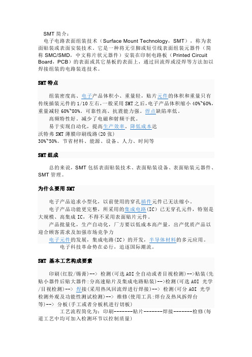
一. 元件數據的輸入(Part Data Entry for SMD3 <F4G Ver.> )1PD(part data)必須輸入的項目:a. the nozzle size (吸嘴尺寸)b. camera type (相機類型)c. the vision type (影像模型類型)d. several item in tolerance_information and EL_data in case of leads parts(部分項目公差和電氣參數<對於有引腳的元件> )2necessary Part Data items (零件數據必須的項目)<1> reference data (參考數據)a. type name (類型名稱)b. package name (包裝名稱)c. direction (包裝方向)d. 90 turn to read (轉90度後再讀取參數)<2>vision data (影象數據)a. vision type (影象類型) f. pitch Limit (間距極限)b. body X and Y Size (本體X和Y方向尺寸)g. height (元件高度<適用于HP機器> )c. body X and Y tolerance (本體公差)h. scan Area X and Y (X和Y掃描區域)d. check window area (檢查窗口區域)i. Lead btihtness (引腳亮度)e. check Limit (檢查極限)<3>check mode (檢查方式)a. check mode (檢查方式)b. CCD Level (CCD相機亮度)c. check area X1,X2,Y1,Y2 (掃描設定的窗口)d. body color (本體色彩)e. algorithm (計算規則)<4>Tolerance__information (公差信息)a. body size X and Y tol. (本體公差)b. tolerance lead width (引腳寬度公差)c. tolerance lead length (引腳長度公差)d. check Limit (檢查極限)e. tolerance pickup X & Y & Q (拾取X,Y及角度公差)e. check Limit (檢查極限)<5>EL_data (Element data ) <電氣數據>a. side # ( 側邊序列號) f. lead length (引腳長度)b. position X and Y (X和Y方向的位置)g. lead width tol. (引腳寬度公差)c. lead quantity (引腳數量)h. lead length tol. (引腳長度公差)d. lead pitch (引腳間距)i. Lead center tol. (引腳中心公差)e. lead width (引腳寬度)<6>environment (環境設定)a. M/C type (機器類型) f. nozzle size max (最大吸嘴尺寸)b. nozzle type (吸嘴類型)g. camera (相機)c. nozzle name (吸嘴名稱)h. camera type (相機類型)d. nozzle size (吸嘴尺寸)i. Lighting (亮度)e. nozzle size min (最小吸嘴尺寸)j. back light min (最小反光盤尺寸)3Vision Data (影像數據)<1>direction algorithm (方向定義)side "0" (左) side 1 (下) side 2 (右) side 3 (上)<2>parts type data (零件類型數據)a. vision type (1~255)機器使用16進制編碼原則, 取兩位即16的平方256(除去缺省"0"即為255)b. check window Area ( 0 ~~100 % ) {檢查窗口區域)從引腳末端開始計算(以引腳總長作比例)SOP & QFP : 10 ~~ 90 % (Setting 30 % )PLCC & SOJ : 50 ~~ 70 % (Setting 60% )BGA & Flip chip : 50 %c. pitch limit ( 0 ~~ 100 % ) 間距誤差 {如果不輸入則等于預設30%}d. lead brigtness ( 0 ~255 ) 引腳亮度在BGA元件輸入"0"時將自動確定;若輸入 1 ~ 255 時則按輸入值進行測定4Vision TYPE (影像類型)<1>兩种不同的參考點零件本體中心 : 按PD本体設定的尺寸來進行影像處理計算坐標置件的位置參考點零件中心 : 按PD設定的引腳尺寸或影像測得的平面數據計算置件坐標的元件中心點(有一邊,三邊或部分不對稱引腳BGA類元件本體中心与零件中心不重合)<2>目前G-COM最常用的影像類型10矩形(適用於所有無引腳之矩形元件)12甜甜圈 (橢圓形) 即 odd,MELF (如二極體,電容適用)20SOT Type (適用于電晶体,晶閘体,兩邊引腳<引腳數雙邊和小于等于6)100IC類元件 ( 使用背光<BackLight> )120PLCC (適用於四面引腳內卷式元件)123IC類元件 (使用黑色吸嘴,前光)230BGA ( 錫球陣列引腳類元件<可帶孔> )254不規則元件,只檢查零件中心,且作校正置件處理255只檢查有無元件,不作影像檢查校正處理( F.L=Front Lighting B.L=Back Lighting BG=Background )未加括號的以零件本體中心為參考點,加括號的則以零件中心為參考點5Algorithm ( 影像類型算法規則詳細描述 )<1>10 Rectangular chips (矩形元件)<2>12 Resistor networks , MELFs , Glass tube diodes (排阻,圓形倒角矩形,桶形玻璃二極体)( 只需要本體尺寸即可,不需要EL_data )<3>11Tantalum spragues (條狀鉭質電容類)13Tantalum spragues (with polarity check) <相對於11增加極性檢查><3>20 SOT__Type devices (SOT類元件)說明: 不能用於電源三極管 , 四引腳SOTs和其它有極性元件如果20影像不適當可用100代替( CP6 , IP_3E & QP242E )<4>21 Trimmer resistor , Trimmer capacitors (微調電阻,微調電容)(同10,長度計算包括引腳在內)<5>22HEMT (Supplied at 0度 )23HEMT (Supplied at 45度 )(十字形元件,規則同10,但需輸入EL__data )<6>24 Trimmer Resistor , Trimmer Capacitor (with polarity check )(需輸入BodySize和EL_data ,計算BodySize時不包括引腳長度,且只適于2或3條引腳類元件)<7>30 Round shape parts (圓形零件 <無方向> )<8>40 Body detection processing ( 本体偵測處理) 使用白色反光盤(需輸入BodySize和EL_data)<9>100(105) IC - Type parts ( IC類元件)使用白色反光盤,光源用背光<10>120 (125) J_lead parts (F.L 1 Background : White ) 引腳內彎式元件 <用前光,白色反光盤>121 (126) J_lead parts (F.L 2 Background : White ) 引腳內彎式元件 <用前光,白色反光盤> 122 (127) J_lead parts (F.L 3 Background : White ) 引腳內彎式元件 <用前光,白色反光盤>注:120(125) :Used for that are larger than the reflective disk (適於零件大於反光盤) 121(126) :Used for that are smaller than the reflective disk (適於零件小於反光盤)122(127) :Used for that are larger than the reflective disk (適於零件大於反光盤)( 若122不能影像可改用120 )<11>123(128) IC - Type parts (F.L) IC類元件 (用前光)124(129) J - lead parts (F.L) 引腳內彎式元件 (用前光)注: 需使用黑色反光盤的吸嘴,且必須輸入BodySize和EL_data<12>130(135) Black body BGAs (F.L) 黑色本體類BGA (用前光)131(136) White body BGAs (F.L) 白色本體類BGA (用前光)需使用黑色反光盤的吸嘴,且必須輸入BodySize和EL_data如有以下類似情形影像處理將不能通過:a. Device for which there are variations in the body color or the image of the ball grid(本體顏色或錫球顏色是變化不確定的裝置)b.Devices for which is difficult to distinguish between the body and the ball grid(本體和錫球之間辨識困難的白色本體裝置)c. Devces with no ball grid art the center of the body(本體中心沒有錫球的裝置<即錫球面非全點陣,帶有空位> )d. Devices which have a pattern on the bottom surface(在反面<非錫球面>有圖案模型的裝置 )<13>140(145) Flip chips (F.L)需使用黑色反光盤的吸嘴,且必須輸入BodySize和EL_data<14>150(155) M/C chuck (B.L BG : White )151(156) M/C chuck (F.L BG: Black )152(157) Black body parts inspected (F.L BG: Black )153(158) White body parts inspected (F.L BG: Black )154 M/C chuck part exsitance chuck inspected with back lighting159 M/C chuck part exsitance chuck inspected with front lighting(154,159必須在置件前檢查PCB上的元件定位Mark點)以上均為IP-3(E)裝機械式夾子時所使用之影像類型,此處略過<15>160(165) body detection (F.L) 本體偵測 <用於校正機器讀處理的時間>需使用黑色反光盤的吸嘴,且必須輸入BodySize和EL_data<16>170 Mechanical chuck part existence check (F.L) 用於IPC-3(E)使用電磁吸盤時<17>180(185) Two lead parts (F.L BG: Black ) 兩個(對)引腳的零件 <用前光,黑色吸嘴>用於處理引腳光亮,本體為黑色且有兩個或兩對對稱引腳的元件注意: a. 元件引腳最大為4,大於4不能完成影像處理b. 引腳局部亮度或亮度不均勻均不能完成影像處理c. 用nozzle時在NAT data或proper data之nozzle項目輸入一個近似於零件兩倍的尺寸數據<18>230(235) Black body BGAs (F.L)黑色本體BGA (用前光)231(236) White body BGAs (F.L)白色本體BGA (用前光)233(238) Black body CSPs (F.L)黑色本體CSP (用前光)234(239) White body CSPs (F.L)白色本體CSP (用前光)設定零件數據之步驟與130和131一樣,除在EL_data結果(Result)項目輸入"9"代替"1"230,231,235,236檢測選Cut(切角),check Area X1,X2,Y1,Y2為左上角和右下角的窗口定位點<19>232(237) TBGAs (F.L BG: White ) 帶邊框的BGA <前光,白色反光盤)僅用於IP-3(E) ,需輸入BodySize和EL_data注: 靠邊框不可以設定有錫球(在EL_data)<20>249 Diagonal cut_shield processing (斜角屏處理)適用於有一條線段(邊)直線和斜線比大於50%的元件,如果斜邊比率小於50%斜邊數量沒有限定,位置不作限定,(254在有斜邊的元件處理時會產生角度偏移)(需輸入BodySize和Side_data,不需EL_data )check window Area 輸入為 "0" , P parttern設為 "2" , Result 設為 "1"<21>250 QP242E Coplanarity check jig (F.L)(QP242前光共面性檢查治具使用)<22>252 White parts (F.L) 白色零件 <前光>(適用於白色和金色本體元件,處理時尋找四個角點進行)<23>253 Dummy data settings (用於檢查機器的影像處理操作)測試影像處理時間及校正反應時間和校正精度<24>254 Ierregular - shaped devices (不規則類型裝置)只尋找X,Y尺寸及元件中心作位置校正處理<25>255 No correction processing (不校正處理)只作檢查有無元件,不檢查方向,不作校正處理二Tolerance information (公差信息處理規則)1body size X , Y tolerance (本體X,Y方向公差)(個別元件近似等于10% , 最小值為 0.2 mm 最大值為2.0mm 2Tolerance lead width (length) (此項目SMD3不需要輸入)3Tolerance pickup X , Y , Q (零件拾取誤差)(輸入在50 ~~ 100 % 之間<零件本體的>,最大值2.0mm,最小值0.5mm 4check limit (輸入引腳可偵測結果可接受的比例 )三EL_data (電氣數據輸入規則)12Result (測試結果)Setting Input value No lead inspection(不偵測)0Lead inspection (偵測)1No lead length inspection(不偵測引腳長度)4No lead width inspection(不偵測引腳寬度)8Right side exta lead inspection (右側突出部偵測)32Left side exta lead inspection (左側突出部偵測)16Virtual lead inspection (虛擬引腳偵測)2Second line of mnatrix_type(點陣類的第二條線偵測)128四Error code of vision processing (影像處理錯誤代碼)1錯誤代碼類型說明1CAXXXXX :Inspection parts(零件影像偵測錯誤代碼)1CB01XXX :Calibration(機器校正錯誤代碼)1CB02XXX :Nozzle centering(吸嘴中心偵測錯誤代碼)1CB03XXX :Inspection fiducial marks (基準點偵測錯誤代碼)1CCXXXXX :Performing Fst-pin check (IP-3(E)第一腳偵測錯誤代碼) 2錯誤代碼編碼原則1C A XX XXX1C: Vision processing error (影像處理錯誤)A: Type of process (處理類型)XX: Vision processing algorithm ( 01 ~ FF ) <影像處理計算規則代碼XXX: Error nubmers for each algorithm ( 000 ~ FFF ) <每個規則代碼的錯誤代碼序列號>五部分專用名詞解釋QFP : quad flat package 四方形低平式包裝PLCC: Plastic leaded chip carrier塑膠平貼式引腳托架SOIC : Small outline intergrate circuit小型綜合線路SOJ : Small outline J-lead小型"J"型引腳器件(P)BGA: Ball grid array球型陣列包裝SOP: Small outline package小輪廓型包裝QFP, SOIC,SOP PLCC BGA SOJ。
SMT/SMD Components Counter Functions &OperatingInstructionProduct Introduction:-Matters Need AttentionFunction Keys And Operation Procedures InstructionsHow To Connect The Printer Operation(selective use)Simple Trouble ShootingProduct IntroductionPrinciple of the product:-The SMD counter adopts the principle of photoelectric sensing,and uses the corresponding relation between the guide hole and the part,through the special-purpose processing chip and the large-scale centralized circuit processing,realizes the zero error,accurately measures the number of SMD parts,can realize the convenient and quick count,is the high efficiency auxiliary equipment of SMT material management.Product features:-Completely automatic way computation components quantity,facilitates a material,sends the material work simplicity of operator,has a special inventive mind against material belt will fall off the design to reduce to the material belt’s injury to the smallest,forward and reverse all may count,but preinstall quantity,will calculate quantity precisely,zero error.May install the scanning gun and the bar code printer,facilitates the management work.Product specifications:-Power supply: AC220V,/A100V 50/60 HZ, 25WCounting range: -99999- 99999PCSOutlook size: L470*W300*H180mmWeight:10 kgProduct applicationThe SMD material belt type components are all suitableDiameter of belt wheel:Any size is all suitablePITCH: 1,2,4,8,10,12,16,24,32,44,56 mmWIDTH: 4,6,8,12,16,24,32,44,56mm (note: smaller or wider distance can be developed or customized according to demand)Product construction:-Two kind of models1-Ordinary components counter2-Leak hunting components counter1.Charging mirror2.Tray3.Gear/movable blanks4.Wrench5.Rocket head6.Movable arm7.Display8.Power switch9.keys10.Handle11.Fiber optic amplifier12.Optical fiber buttMatters need attention1.After unpacking, please check if all the attachments are complete.2.Please read the operation manual carefully before using and keep it properly.3.Check whether the voltage specification is consistent with that ofmunicipal power.4Please make sure to connect the ground wire to ensure the safety of the person and parts.Function Keys And Operation Procedures Instructions1、功能说明1)PRINT”Operation method: press this button, the number of parts and quantities can be counted by the barcode printer.2)“SET”If "00000" is displayed at the lower left corner of the display screen, you can directly press the number key to enter the number of parts to be calculated: press the "SET" key again to change to manual mode, and "****" is displayed at the lower left corner of the display screen. Manual and automatic modes are switched through this key. (note: the automatic mode is the preset value before the disk material, and the machine will stop automatically when it rotates to the set value. In the manual mode, the machine will stop only when the "stop/reset" key is pressed manually or all materials are finished.)Operation method: after pressing this button, the PITCH value of the display screen will flash, then input the spacing of materials, and then press the "ENTER" button to confirm. If no button is pressed for 5 seconds, the memory will be automatically memorized, and the sound of a drip will be returned to standby state.4)“正传Positive direction/RIGHT”Operation method: press this button to start counting parts in the positive direction, that is, the number shows a positive number or increases. When printing, press this button to move the cursor to the right to set the parameters.5)“The opposite direction/LEFT”Operation method: press this button to start counting parts in the opposite direction, that is, the number displays negative number or decreases. When printing, press this button to move the cursor to the left to set the parameters.6)“STOP/RESET”Operation method:-1.In the state of counting or returning, press this button to stop counting or returning.2.In standby mode, press this button for more than two seconds to clear the COUNT value.3.Press this button when printing the interface to return to the main interface.4.Press this button to stop and return to the standby screen during self-test.Operation method: in standby mode, press this button for 1 second, and the machine conducts self-check test; In automatic mode, press this key to clear the set number; Set the toggle button for the print interface parameters when printing.8)“ LOSS”Operation method: press this button to turn on or off the function of Leak hunting9)“ TIME”Operation method: this button is the switching key of motor speed. Press this button, and the LCD screen will switch between H(high speed), M (medium speed) and L(low speed).10)“ENTER”Operation method: when setting parameters in the print interface, press this button to save the parameters set.2、操作流程Operation process1) connect the power cord to the host and connect the AC220V power supply2) turn on the POWER switch of the machine panel, and the LCD panel will shine3) press PITCH to set the spacing of parts to be counted and press "ENTER". Place the parts to count on the left side tray.4) manually pull out the material belt and clamp it between the material plate and counting gear, and align the intermediate hole of the first part and blank space to the middle line of the material plate.5) press the "stop/reset" button for 2 seconds to return the number to zero. Note: when pulling the material belt, the counting gear will rotate and count.6) press the "setting" button to switch to manual and automatic mode. If you choose automatic mode, you must input the quantity you want to count. Otherwise, press "forward" and the motor will not rotate.7) pull the material belt by hand and wind it to the empty material plate. Press "forward /RIGHT" to count.8) the motor will stop when the quantity arrives. Due to the inertia principle, the number of counts may be more or less than the set value of about 1, which can be manually rotated to the LCD display set value in the direction of the material disk, that is, the number of parts.9) after counting, press "reverse /LEFT" tape and then roll it back to the original LEFT panel, and then stop rotating.三、贴片计数器了解打印机操作说明(选用)How To Connect The Printer Operation(selective use)1、Inspecting device1) make sure the parts counter and BAR code host are connected2) make sure the bar code printer paper is installed correctly.2、Debugging device1) start the part counter power switch2) start the power switch of the host of BAR CODE: power indicator light and ready indicator light are on. At this time, press the FEED key of the host of BAR CODE (automatic alignment button) to make the printing paper automatic alignment. (P.S: if the POWER light is flashing, which means the machine is broken, please restart the POWER switch or FEED key and execute3、PrintPress "PRINT" on the main interface to display the PRINT interface, and the first line of the word interface shows: company name (self-setting); The second line shows the print operation.1) after entering the print interface, there will be a blinking cursor on the third line. At the cursor point again, the content can be edited and modified.2) in the print interface, press LEFT/ reverse to move the cursor to the LEFT, and press RIGHT/ forward to move the cursor to the RIGHT.3) enter Numbers and letters directly at the cursor. If you press a button in the 0--9 key continuously for a short time, you can switch between Numbers and letters on the key. Where the 1 key is used to switch special symbols, letter case and so on.4) after editing the lines, the cursor stays at the line. Press ENTER to display OK on the left side of the line and save the contents of the line. (note: save the editing lines must be the cursor in the line location and then press the ENTER key to deposit, for example: if you want to save the first and second lines, must be the cursor at the first line by pressing the ENTER key, can keep the contents of the first line, the cursor in the second row content save xiali, not at the same time save)5) SELECT to enter the interface of printing parameters on the print interface, where XYWH:XXX, XXX, XXX are displayed respectively to set the position X, Y, width and height of the printed barcode.6) press the stop/reset button to return to the main page7) press PRINT again to PRINT the contents of the PRINT interfaceAdditional attached: the scanner will display on the printing interface after scanning the bar code, press the print button to print.四、简易故障排除 Simple trouble shooting故障状况Fault conditions排除方法Elimination methods打开电源后LCD 无任何显示,无蜂鸣器响声After power on the LCD without any display, no buzzer sound电源线脱落或保险丝松动,请检查 Please check the power cord or loose fuse打开电源后LCD 无任何显示,有蜂鸣器响声The LCD has no display when the power is turned on LCD 屏线松动或损坏,请检查或联系销售商更换 LCD screen line is loose or damaged, please check or contact the seller for replacementLCD 正常显示,但按正/反转启动无效LCD display is normal, butpositive/reverse startup is invalid1. 计数数量大于或等于设定数量或盘料前选用自动模式未设定数,请参阅说明说操作须知2. 电机信号线或电源线接触不良1. The number of counts is greater than or equal to the set number or the number is not set in the automatic mode before feeding. Please refer to the instructions for operation2. Bad contact between motor signal line or power line。