DO-160G 机载设备适航符合性验证试验之电磁兼容
- 格式:docx
- 大小:18.16 KB
- 文档页数:2

技术编写:185********谌伦文现简述一下民航机载设备RTCA/DO-160标准EMC测试方法和过程:D0-160F简介RTCA/DO-160F,是由RTCA 135特别委员会制定并于2007年12月6日发布的航空设备环境条件和测试步骤的标准。
DO-160F涵盖了航空电气电子设备(航空电子学)的标准步骤和环境测试标准。
在DO-160F中测试和测试等级/限值适用于当前实际使用的所有类型的飞行器,包括小型通用航空器、商业喷气式飞机、直升机、区域喷气式飞机和巨型喷气式飞机,例如最新的空中客车(A380)和波音客机(787)。
DO-160F的制定和修正与RTCA的欧盟版本:EUROCAE相配合。
作为横跨大西洋的两个组织的合作成果,RTCA/DO-160F与他的欧洲版本EUROCAE/ED-14F完全一致。
本文旨在对DO-160F中与EMC有关的测试项目进行简要的说明。
DO-160F标准中EMC测试项目DO-160F中关于EMC测试的项目主要集中在从第16节到23节以及25节中。
具体为:第16节,电源输入试验第17节,电压尖峰试验第18节,音频传导敏感度试验(闭环测试)第19节,感应信号敏感度试验第20节,射频敏感性试验第21节,射频能量发射试验第22节,雷击感应瞬间敏感性试验第23节,雷击直接影响试验第25节,静电放电试验EMC测试内容说明(部分)1.电源输入试验此项测试分为AC输入测试、DC输入测试。
用来确定由于飞行器正常和紧急操作引起的AC 和DC电源的各种变化情况下,EUT可否正常运行。
其中:直流输入测试包括:稳态过电压与低电压状况,纹波电压,瞬时电源中断,瞬时跌落与浪涌,暴露电压衰减时间(仅对270V电压),瞬间电流。
交流输入测试包括:稳态过电压和低电压的情况,稳态高频与降频的情况,稳态相位不平衡(三相电),电压与频率调制,电压与频率瞬变,瞬间电源中断,瞬间跌落与浪涌,直流偏置和电压畸变,谐波电流发射,相位不平衡(三相电输入),直流电源分量,瞬间电流,电流调制,功率因数。

RTCA/DO-160G环境试验条件解读4.0温度、高度试验4.5.1 地面耐受低温试验和低温短时工作试验在环境大气压力下,设备不工作,将设备温度稳定于表4-1 规定的地面耐受低温至少3 小时。
设备不工作,使其按表4-1 中提供的短时工作低温存放至少30 分钟。
保持试验箱内的温度继续为表4-1 提供的相应的短时工作低温,使设备至少工作30 分钟。
4.5.2 低温工作试验在环境大气压力下,设备工作,将试验箱的温度设置为按照表4-1 查出的相应的工作低温。
当试验箱的温度稳定后,使受试机载设备的工作时间不少于2 小时,并维持试验箱温度在预先选定的相应工作低温。
4.5.3 地面耐受高温试验和高温短时工作试验在环境大气下,设备不工作,将设备稳定于表4-1 规定的相应的地面耐受高温中至少3 小时。
设备不工作,使其按表4-1 提供的相应短时工作高温存放至少30 分钟。
使试验箱温度继续维持在按表4-1 所查出的相应短时工作高温,设备至少工作30 分钟。
在设备工作期间,确定是否符合有关设备性能标准。
4.5.4 高温工作试验在环境大气压力下,将试验箱的温度设置为表4-1 规定的相应高温工作温度,待温度稳定后,使设备至少持续工作2 小时,并维持试验箱内温度稳定在按表4-1 预先查出相应的高温工作温度。
在设备工作期间,确定是否符合相关设备性能标准。
4.5.5 飞行中冷却能力损失试验飞行中冷却能力损失试验的时间长度定义为冷却装置不工作的时间。
类V----最少30 分钟;类W----最少90 分钟;类P----最少180 分钟;类Y----最少300 分钟;Z 类----由设备技术条件规定。
设备工作在环境大气压力下,按照3.4 节中规定的条件供应冷却空气,调整试验箱内温度到表4-1 中冷却能力损失试验时所规定的温度,并保持温度稳定。
关闭设备的冷却空气供应,保持试验箱的温度在表4-1 所规定的温度,使设备持续工作时间达到相应类别的试验时间,确定是否符合有关设备性能标准。

航空机载产品测试Airborne Equipment Test机载产品的环境试验与服役的机种、机型、安装位置、⻜⾏任务剖⾯,有着紧密的联系。
参照机载设备各系统的产品通⽤规范、技术标准等条件,总结以往航空机载设备环境试验的规范,可靠性与环境试验中⼼的环境试验⼯程师⻅“机”⾏事,为客⼾提供试验⽅案设计、试验实施和试验结果判定的⼀站式服务。
特点Characteristics开展航空机载产品如⻜⾏控制系统、⻜机燃油系统、电⽓系统、卫星通信系统等环境试验、可靠性摸底试验、可靠性强化试验、可靠性鉴定试验及可靠性验收试验,为客⼾提供合理的可靠性试验⼤纲、加速寿命⽅案、可靠性评估⽅案等,从⽽验证和评估产品的MTBF值,保障产品的可靠性。
试验项⽬Test ItemsSection4Temperature and AltitudeSection5Temperature VariationSection6HumiditySection7Operational Shocks and Crash SafetySection8VibrationSection9Explosive AtmosphereSection10WaterproofnessSection11Fluid SusceptibilitySection12Sand and DustSection13FungusSection14Salt FogSection15Magnetic EffectSection16Power InputSection17Voltage SpikeSection18Audio Frequency Conducted Susceptibility-Power InputsSection19Induced Signal SusceptibilitySection20Radio Frequency Susceptibility(Radiated and Conducted)Section21Emission of Radio Frequency EnergySection22Lightning Induced Transient SusceptibilitySection24IcingSection25Electrostatic Discharge(ESD)Section26Fire and Flammability重点项⽬介绍Key project introduction特⾊试验⽅案Special test scheme某研究中⼼委托我司进⾏RTCA/DO-160试验项⽬,受试产品为C919燃油系统部件。
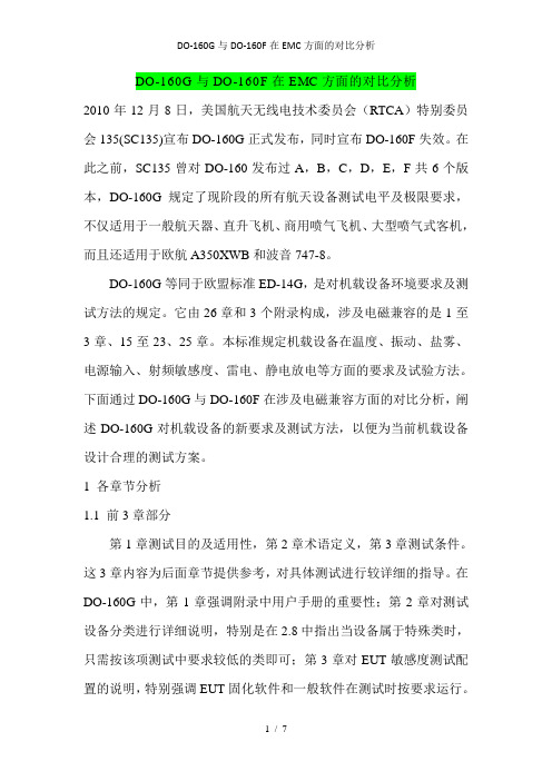
DO-160G与DO-160F在EMC方面的对比分析2010年12月8日,美国航天无线电技术委员会(RTCA)特别委员会135(SC135)宣布DO-160G正式发布,同时宣布DO-160F失效。
在此之前,SC135曾对DO-160发布过A,B,C,D,E,F共6个版本,DO-160G规定了现阶段的所有航天设备测试电平及极限要求,不仅适用于一般航天器、直升飞机、商用喷气飞机、大型喷气式客机,而且还适用于欧航A350XWB和波音747-8。
DO-160G等同于欧盟标准ED-14G,是对机载设备环境要求及测试方法的规定。
它由26章和3个附录构成,涉及电磁兼容的是1至3章、15至23、25章。
本标准规定机载设备在温度、振动、盐雾、电源输入、射频敏感度、雷电、静电放电等方面的要求及试验方法。
下面通过DO-160G与DO-160F在涉及电磁兼容方面的对比分析,阐述DO-160G对机载设备的新要求及测试方法,以便为当前机载设备设计合理的测试方案。
1 各章节分析1.1 前3章部分第1章测试目的及适用性,第2章术语定义,第3章测试条件。
这3章内容为后面章节提供参考,对具体测试进行较详细的指导。
在DO-160G中,第1章强调附录中用户手册的重要性;第2章对测试设备分类进行详细说明,特别是在2.8中指出当设备属于特殊类时,只需按该项测试中要求较低的类即可;第3章对EUT敏感度测试配置的说明,特别强调EUT固化软件和一般软件在测试时按要求运行。
验证EUT产生的磁场对环境的影响,通过罗盘指针或磁场探头进行指示其大小,也被称为“磁阀”。
试验时将EUT沿着东西连线方向逐渐接近标准罗盘,直到观察指针产生一度的偏移,测量其间距从而确定“设备分类”。
根据间距从小于30cm到大于300cm将设备分为5个等级(Y,Z,A,B和C)。
在DO-160G中,对图15-1试验测试配置进行修改,以便确定当罗盘指针偏移1°时罗盘与被测设备间的距离,从而确定设备等级。

机载WiFi设备电磁兼容试验方案探讨
刘学
【期刊名称】《航空电子技术》
【年(卷),期】2018(049)0z1
【摘要】主要针对机载WiFi设备采用机内天线的特点,探讨机载WiFi设备性能规范,以及内置天线对基于DO-160G标准的EMC试验影响,并提出一些应对措施.【总页数】4页(P140-143)
【作者】刘学
【作者单位】中电科航空电子有限公司,成都611731
【正文语种】中文
【中图分类】O441
【相关文献】
1.飞机加装机载WIFI系统电磁兼容性研究 [J], 李建峰;
2.机载设备可靠性统计试验方案研究 [J], 朱海游;万伟稼
3.机载武器及其双配套设备可靠性鉴定试验方案的分析 [J], 孟玥然;王欣;祝耀昌
4.机载WIFI信号对DME导航设备电磁干扰研究 [J], 雷楚良; 张剑; 罗县文
5.某型机载设备电磁兼容性设计及后续思考 [J], 李亚凤
因版权原因,仅展示原文概要,查看原文内容请购买。

DO-160G与DO-160F在EMC方面的对比分析2010年12月8日,美国航天无线电技术委员会(RTCA)特别委员会135(SC135)宣布DO-160G正式发布,同时宣布DO-160F失效。
在此之前,SC135曾对DO-160发布过A,B,C,D,E,F共6个版本,DO-160G规定了现阶段的所有航天设备测试电平及极限要求,不仅适用于一般航天器、直升飞机、商用喷气飞机、大型喷气式客机,而且还适用于欧航A350XWB和波音747-8。
DO-160G等同于欧盟标准ED-14G,是对机载设备环境要求及测试方法的规定。
它由26章和3个附录构成,涉及电磁兼容的是1至3章、15至23、25章。
本标准规定机载设备在温度、振动、盐雾、电源输入、射频敏感度、雷电、静电放电等方面的要求及试验方法。
下面通过DO-160G与DO-160F在涉及电磁兼容方面的对比分析,阐述DO-160G对机载设备的新要求及测试方法,以便为当前机载设备设计合理的测试方案。
1 各章节分析1.1 前3章部分第1章测试目的及适用性,第2章术语定义,第3章测试条件。
这3章内容为后面章节提供参考,对具体测试进行较详细的指导。
在DO-160G中,第1章强调附录中用户手册的重要性;第2章对测试设备分类进行详细说明,特别是在2.8中指出当设备属于特殊类时,只需按该项测试中要求较低的类即可;第3章对EUT敏感度测试配置的说明,特别强调EUT固化软件和一般软件在测试时按要求运行。
验证EUT产生的磁场对环境的影响,通过罗盘指针或磁场探头进行指示其大小,也被称为“磁阀”。
试验时将EUT沿着东西连线方向逐渐接近标准罗盘,直到观察指针产生一度的偏移,测量其间距从而确定“设备分类”。
根据间距从小于30cm到大于300cm将设备分为5个等级(Y,Z,A,B和C)。
在DO-160G中,对图15-1试验测试配置进行修改,以便确定当罗盘指针偏移1°时罗盘与被测设备间的距离,从而确定设备等级。
关于RTCA/DO-160G机载设备环境试验条件解读RTCA/DO-160G环境试验条件解读4.0温度、高度试验4.5.1 地面耐受低温试验和低温短时工作试验在环境大气压力下,设备不工作,将设备温度稳定于表4-1 规定的地面耐受低温至少3 小时。
设备不工作,使其按表4-1 中提供的短时工作低温存放至少30 分钟。
保持试验箱内的温度继续为表4-1 提供的相应的短时工作低温,使设备至少工作30 分钟。
4.5.2 低温工作试验在环境大气压力下,设备工作,将试验箱的温度设置为按照表4-1 查出的相应的工作低温。
当试验箱的温度稳定后,使受试机载设备的工作时间不少于2 小时,并维持试验箱温度在预先选定的相应工作低温。
4.5.3 地面耐受高温试验和高温短时工作试验在环境大气下,设备不工作,将设备稳定于表4-1 规定的相应的地面耐受高温中至少3 小时。
设备不工作,使其按表4-1 提供的相应短时工作高温存放至少30 分钟。
使试验箱温度继续维持在按表4-1 所查出的相应短时工作高温,设备至少工作30 分钟。
在设备工作期间,确定是否符合有关设备性能标准。
4.5.4 高温工作试验在环境大气压力下,将试验箱的温度设置为表4-1 规定的相应高温工作温度,待温度稳定后,使设备至少持续工作2 小时,并维持试验箱内温度稳定在按表4-1 预先查出相应的高温工作温度。
在设备工作期间,确定是否符合相关设备性能标准。
4.5.5 飞行中冷却能力损失试验飞行中冷却能力损失试验的时间长度定义为冷却装置不工作的时间。
类 V----最少30 分钟;类 W----最少90 分钟;类 P----最少180 分钟;类 Y----最少300 分钟;Z 类----由设备技术条件规定。
设备工作在环境大气压力下,按照3.4 节中规定的条件供应冷却空气,调整试验箱内温度到表4-1 中冷却能力损失试验时所规定的温度,并保持温度稳定。
关闭设备的冷却空气供应,保持试验箱的温度在表4-1 所规定的温度,使设备持续工作时间达到相应类别的试验时间,确定是否符合有关设备性能标准。
Do-160G标准第16章是关于电源输入的试验项目,本章对于航空电子设备的电源输入进行了全面的评估和测试,以确保其在航空环境下的可靠性和稳定性。
在这篇文章中,我将根据这一主题深入探讨并撰写一篇有价值的文章。
**1. 了解DO-160G标准**让我们了解一下DO-160G标准。
DO-160标准是美国联邦航空局(FAA)批准的适航标准之一,用于评估航空航天电子设备在航空环境下的适航性。
DO-160G标准作为电子设备适航测试的国际通用标准,其中第16章是关于电源输入的试验项目,对电源输入进行了全面的评估和测试。
**2. 电源输入的重要性**电源输入是航空电子设备正常运行的关键要素之一。
在航空环境下,电源输入可能受到各种不同电压、频率和波形的影响,因此需要进行相应的试验来验证设备在各种条件下的稳定性和可靠性。
DO-160G第16章的电源输入试验项目旨在确保航空电子设备能够在各种电源输入条件下正常工作。
**3. DO-160G第16章的试验项目**在DO-160G标准的第16章中,包含了一系列的试验项目,例如直流输入、交流输入、瞬态输入、不间断电源输入等。
这些试验项目会对电源输入进行各种条件下的测试,包括过载、瞬态、电压波动、频率变化等,以验证电子设备的适航性能。
**4. 个人观点和理解**在我个人看来,DO-160G第16章的电源输入试验项目是非常重要的,因为电源输入是航空电子设备正常运行的基础。
在航空环境下,电源输入可能面临各种复杂的情况,如气候变化、电网不稳定等,因此对电源输入进行全面的评估和测试是至关重要的。
**5. 总结与回顾**DO-160G第16章的电源输入试验项目对于航空电子设备的适航测试非常重要。
通过对电源输入的全面评估和测试,可以确保航空电子设备在各种复杂条件下的可靠性和稳定性。
在设计和制造航空电子设备时,必须严格遵循DO-160G标准第16章的相关规定,以确保设备的适航性能。
通过这篇文章的撰写,我对DO-160G标准第16章的电源输入试验项目有了更深入的理解,也对航空电子设备的设计和制造有了更全面的认识。
RTCA/DO-160G环境试验条件解读4.0温度、高度试验4.5.1 地面耐受低温试验和低温短时工作试验在环境大气压力下,设备不工作,将设备温度稳定于表4-1 规定的地面耐受低温至少3 小时。
设备不工作,使其按表4-1 中提供的短时工作低温存放至少30 分钟。
保持试验箱内的温度继续为表4-1 提供的相应的短时工作低温,使设备至少工作30 分钟。
4.5.2 低温工作试验在环境大气压力下,设备工作,将试验箱的温度设置为按照表4-1 查出的相应的工作低温。
当试验箱的温度稳定后,使受试机载设备的工作时间不少于2 小时,并维持试验箱温度在预先选定的相应工作低温。
4.5.3 地面耐受高温试验和高温短时工作试验在环境大气下,设备不工作,将设备稳定于表4-1 规定的相应的地面耐受高温中至少3 小时。
设备不工作,使其按表4-1 提供的相应短时工作高温存放至少30 分钟。
使试验箱温度继续维持在按表4-1 所查出的相应短时工作高温,设备至少工作30 分钟。
在设备工作期间,确定是否符合有关设备性能标准。
4.5.4 高温工作试验在环境大气压力下,将试验箱的温度设置为表4-1 规定的相应高温工作温度,待温度稳定后,使设备至少持续工作2 小时,并维持试验箱内温度稳定在按表4-1 预先查出相应的高温工作温度。
在设备工作期间,确定是否符合相关设备性能标准。
4.5.5 飞行中冷却能力损失试验飞行中冷却能力损失试验的时间长度定义为冷却装置不工作的时间。
类V----最少30 分钟;类W----最少90 分钟;类P----最少180 分钟;类Y----最少300 分钟;Z 类----由设备技术条件规定。
设备工作在环境大气压力下,按照3.4 节中规定的条件供应冷却空气,调整试验箱内温度到表4-1 中冷却能力损失试验时所规定的温度,并保持温度稳定。
关闭设备的冷却空气供应,保持试验箱的温度在表4-1 所规定的温度,使设备持续工作时间达到相应类别的试验时间,确定是否符合有关设备性能标准。
ERIK J. BORGSTROMEnviron Laboratories LLC Bloomington, MNOVERVIEWRTCA/DO-160E, ENVIRONMENTAL CON-ditions and Test Procedures for Airborne, prepared by RTCA Special ent , pr Equipment Committee 135, was issued on December 7, 2004, and superseded DO-160D, Changes 1, 2, and 3.1DO-160E covers standard procedures and environmental test criteria for testing air-borne electronic equipment (avionics) for the entire spectrum of aircraft, from light general aviation aircraft and helicopters through the “Jumbo Jet” classes of aircraft.Th e document includes 26 sections and three Appendices, but it is Sections 15 through 23 and Section 25 that cover EMC. Examples of tests covered in DO-160E include temperature/humidity, vibration, power in-put, radio frequency susceptibility, lightning, and electrostatic discharge.Creation and revision of DO-160E is coordinated with the European Union ver-sion of RTCA, EUROCAE. As a result of this trans-Atlantic cooperation and joint eff ort by the two organizations, RTCA/DO-160E and its European twin, EUROCAE/ED-14E, are identically worded.Th e following is an overview of each of the sections that deal with EMC in DO-160E, along with a summary of the changes in each section since the release of DO-160D, and fi nally, a preview of likely revisions to DO-160.EMC requirements for avionics: RTCA/DO-160ESignifi cant changes to the global standard for aerospace EMC.SECTIONS 1–3Th e fi rst three sections cover the Purpose (Section 1) of DO-160, ity (S and Applicability provide a Defi nition of Terms (Section 2) used throughout the document, and give Conditions of Tests (Section 3). Th ese fi rst three sections are referenced in all of the sub-sequent sections of DO-160 and provide the general information and guidance needed to perform the specifi ed tests properly.What’s New for DO-160E• Section 1.1, covering the history of DO-160 and providing general guidance to users has been added. Th is short section provides valuable information in particular for those to whom DO-160 compliance is a new task.• Section 3.2, covering the order of tests and the use of multiple test articles, was revised to clarify that the tests in DO-160 are not required to be cumulative, meaning that it is not mandatory to use a single test article for all tests. Instead, it is intended that cumulative eff ects of any or all of the tests must be determined by theequipment manufacturer, and the strat-egy to address this issue must be included in the equipment specifi cation or the test plan. In addition, new and revised restric-tions on test order are laid out, such as the requirement that fl ammability testing must always be performed on a given ast on last test article.SECTION 15: MAGNETIC EFFECT Th is test is performed to determine the de-gree to which the equipment-under-test (EUT) will defl ect a compass needle.A standard compass that has a large enough dial to read one degree of needle defl ection is the only test equipment re-quired. Th e EUT is simply moved closer to the compass on an East-West line until one degree of defl ection away from magnetic North is observed. Th e separa-tion distance is then measured and the “Equipment Class” is determined. Equipment ClassesTh ere are four Equipment Classes (A, B, C, and Z) that apply to separation distances of less than 30 centimeters to more than 300 centimeters. What’s New for DO-160E• Section 15.3 provides a much more detailed test procedure than previous versions, including a requirement to verify fi eld uniformity if the compass must be moved to change the mea-surement distance to the EUT.• Th e new Figure 15-1 provides a test setup diagram and gives notes on proper performance of the test. SECTION 16: POWER INPUTTh e tests in this section are performed to determine that the EUT can operate as required during all of the diff erent conditions of AC and/or DC supply variations that occur during normal and emergency aircraft operation. Th ese tests are comparable with the requirements in MIL-STD-704F and cover conditions that range from normal to emergency.2 Change 2 to DO-160D, issued June 12, 2001, revised Section 16 fairly dra-matically, by including new tests, and modifi cations to existing testing, that address the issues of AC Harmonic Content and Variable Frequency AC power systems.Th e harmonic current emissions tests for AC powered avionics are similar to the tests used to show compliance with European Commercial/Residential har-monic current limits (EN61000-3-2).3 Th e Variable Frequency AC power Equipment Categories require testing at the frequency extremes of “Narrow” and “Wide” Variable Frequency power systems.DC Input testsOn DC inputs, there are tests thatcover:• Steady-state over- and under-voltageconditions• Ripple voltage• Momentary power interruption• Momentary sags and surgesAC Input testsAC inputs are subjected to the follow-ing tests:• Steady-state over- and under-voltageconditions• Steady-state over- and under-fre-quency conditions• Steady-state phase unbalance (three-phase power)• Voltage and frequency modulation• Voltage and frequency transients• Momentary power interruption• Momentary sags and surges• DC Offset and Voltage HarmonicDistortion• Harmonic current emissionsEquipment CategoriesTh ere are three Equipment Categories(A, B, or Z) that indicate the type ofpower used by the equipment and thetype of AC and/or DC power sourcewith which the equipment is compat-ible. An additional designator, placedin parentheses following the Categorydesignator for AC powered equipment,is a two-character code indicating thatthe equipment has been tested for usewith Constant Frequency (CF), Nar-row Variable Frequency (NF), or WideVariable Frequency (WF). An additionaldesignator (H) is included to indicatethat harmonic current emissions re-quirements have been met.What’s New for DO-160E• Th e arrangement of the test proce-dure sections has been changed sothat all of the Normal and Abnormalpower input tests applicable to ACpowered equipment are in one sec-tion (16.5), and all of the DC tests arein another section (16.6).• Most of the sections have been revisedto add clarifi cation and details as toproper performance of the specifi edtests, and defi nitions for each of thedifferent AC and DC EquipmentCategories are included. More tablesare used throughout the section,making it much easier to read andunderstand.• For AC powered equipment, a Volt-age DC content test has been added,as well as a Voltage Distortion testwhich requires the EUT to operateproperly with up to 10% Total Har-monic Distortion on the AC voltagewaveform.• Th e AC Harmonic Current Emissionstest has increased the THD level forthe “Test 2” procedure (emissionsin the presence of distorted voltageinput).SECTION 17: VOLTAGE SPIKETh is test determines whether the EUTcan operate as required during and/orafter voltage spikes are applied to the ACand/or DC power input(s). Any methodof generating the spike may be used,provided that the pulse produced has aduration of at least 10 microseconds, arise-time of less than 2 microseconds,and a source impedance of 50 ohms. Aminimum of 50 voltage spikes are ap-plied within 1 minute. Th is test is verysimilar to MIL-STD-462 test methodCS06.4Equipment CategoriesTh ere are two Equipment Categories.Th e Category B test level is twice theAC (rms) and/or DC line voltage (or 200volts, whichever is less). Th e Category Atest level is 600 volts.What’s New for DO-160ENo substantive changes, but formattingand fi gures have been cleaned up foreasier reading.SECTION 18: AUDIO FREQUENCY CONDUCTEDSUSCEPTIBILITY—POWER INPUTSTh is test is performed to determine thatthe EUT will operate as specifi ed whenaudio frequency interference is appliedto the AC and/or DC power input. Th etest setup and procedure are nearlyidentical to MIL-STD 461E test methodCS101; the only diff erence is the actualtest level and frequency range.5 Th e au-dio frequency interference is transformercoupled onto each power input lead, and the peak-to-peak voltage level of the interference signal is measured across the power input and return leads. Test levels are up to 8% of the nominal AC input voltage, and the frequency range is as broad as 10 Hz to 150 kHz.Th e EUT must be tested while oper-ating at both minimum and maximum current draw (if applicable) and at the AC power frequency extremes if desig-nated for use with Variable Frequency systems. Th e frequency scan rate is 30 steps per decade, with a 1 minute dwell time at each frequency. Equipment CategoriesTh ere are three DC power Equipment Categories (R, B, and Z) that indicate the type of power used by the equipment and the type of DC power source with which the equipment is compatible.Th ere are two AC power Equipment Categories (R and K) that indicate the level of distortion with which the EUT is compatible (K is a higher level). An additional designation, placed in pa-rentheses following the Category des-ignator for AC powered equipment, is a two-character code indicating that the equipment has been tested for use with Constant Frequency (CF), Narrow Vari-able Frequency (NF), or Wide Variable Frequency (WF).What’s New for DO-160E• Th e Equipment Category designators A and J have been eliminated, and categories R and K have been added. SECTION 19: INDUCED SIGNAL SUSCEPTIBILITYTh e tests in this section are performed to determine that the EUT can operate as required when the equipment and interconnecting cables are subjected to audio frequency electric fi elds, magnetic fi elds, and transient voltage spikes. Th ese tests are similar to the “Chattering Relay” and power frequency magnetic fi elds test in MIL-STD-462 test method RS02. Th e test levels for the interconnect-ing cable tests are determined by the length of cable that is exposed to the radiating wire. For the induced spikes test, the exposed length is either 1.2 or 3.0 meters, with the amplitude ofthe Inductive Switching Transientsapplied to the radiating wire being atleast 600 V pp.For the magnetic and electric fi eldsinduced into cables, the test level isdefi ned as the product of the length ofinterconnecting cable that is exposed tothe radiating wire and the rms voltageor current applied to the wire. Th is testlevel is given as “volts x meters” (V-m),or “amps x meters” (A-m). For example,category Z requires an electric fi eld testlevel of 1800 V-m, which is typicallyobtained by exposing 3 meters of cableto a radiating wire with 600 volts rmsapplied to it. If less than 3 meters ofcable is exposed to the radiating wire(due to space restrictions, for example),the voltage applied to the wire must beincreased so that the test level of 1800V-m is achieved. An exception to thisrequirement occurs when the actuallength of the cable in the fi nal installa-tion is known to be less than 3 meters. Inthis case, the test level may be reducedin proportion to the ratio of the reducedcoupling length.Th e frequency ranges for the sweptfrequency tests are determined by theEquipment Category specifi ed. Th e fre-quency scan rate is 30 steps per decade,with a 10-second dwell time at eachfrequency.Equipment CategoriesTh e Equipment Categories are indicatedby two characters. Th e fi rst character (A,B, C, or Z) indicates the tests performedand the severity level of the tests. Th esecond character (C, N, or W) indicatesthe AC power system operating fre-quency (Constant, Narrow Variable, orWide Variable) with which the EUT iscompatible.What’s New for DO-160E• A second Equipment Category desig-nator is now used to indicate the ACpower system operating frequency(Constant, Narrow Variable, or WideVariable).• The frequency scan rate is nowspecifi ed to be 30 steps per decade,with a 10-second dwell time at eachfrequency.SECTION 20: RADIO FREQUENCYSUSCEPTIBILITY (Radiated and Conducted)Th ese tests are performed to determinethat equipment will operate as specifi edwhen the EUT and its interconnectingcables are exposed to radio frequencyinterference. Continuous Wave (CW),Square Wave AM (SW), and PulseModulated (PM) RF signals are required;and for some categories, it is requiredto gate the modulated signal on andoff at a 1-Hz rate. A Line ImpedanceStabilization Network (LISN) must beinserted in series with each power leadand ungrounded power return lead, witha 10-µF capacitor connected between thepower input of the LISN and the groundplane. Unless otherwise specifi ed, inter-connecting cables shall be at least 3.3meters in length, and power leads willbe no more than one meter in lengthfor these tests.Conducted SusceptibilityThe RF conducted susceptibility testprocedure is similar to MIL-STD-461Etest method CS114. RF interference iscoupled into the EUT interconnectingcables and power leads using an injectionprobe that is calibrated to the requiredtest level prior to performing the test.Th e calibration is performed in a 50-ohm fi xture. For each test frequency, theamount of RF power applied to the in-jection probe that is required to achievethe specifi ed RF current in the fi xture isrecorded. Th is calibration table, showingRF power required at a given frequency,is then used during the actual test. Th eamount of RF current induced into thecable or lead under test is also monitoredduring the test. Th e test frequency rangeis 10 kHz to 400 MHz.Radiated SusceptibilityThe RF radiated susceptibility testprocedure is similar to MIL-STD-461Etest method RS103. Th e EUT and itsinterconnecting cables and power leadsare exposed to RF radiated fi elds in thefrequency range of 100 MHz to 18 GHz.Th ere are two RF radiated susceptibil-ity test methods allowed in Section 20.Th e fi rst uses a standard semi-anechoicchamber as in MIL-STD-461E testmethod RS103. Calibration of the RFfi eld prior to placement of the EUT is required. For each antenna used, the RF power required to achieve the specifi ed test level when applied to the antenna input is recorded. Th e chamber must be lined with RF absorber, and the minimum performance of that absorber is specifi ed. Th e minimum antenna distance is 1 meter, and multiple antenna positions are required when the beamwidth of the antenna does not totally cover the system.Th e second method uses a Mode-Tuned Reverberation Chamber, which requires a Field Uniformity Validation and Maximum Chamber Loading Verifi cation prior to the fi rst use of the chamber or after any modifi cations. Field Uniformity and maximum Electric Field Strength measurements are performed with a 3-axis E-Field probe at up to nine diff erent positions within the chamber. In addition, a passive, linear, antenna is moved to diff erent positions within the chamber to calibrate the antenna for use prior to each test. Th is calibra-tion allows the antenna to be used to measure Chamber Q, Time Constant, and Chamber Loading Factor, during EUT testing.Change 1 to DO-160D, issued December 14, 2000, revised Section 20 extensively. Th e revisions to Section 20 were liter-ally a decade in the making and refl ected the state-of-the-art for RF Susceptibility testing, including a new, cutting-edge Mode-Tuned, Reverb Chamber Radiated RF Susceptibility test method. New categories (test levels) were also added to Section 20, including Category L, which requires Radiated RF Susceptibility testing (pulsed) as high as 7200 Volts/meter! Equipment CategoriesEquipment Category designation for Section 20 consists of two letters. Conducted susceptibility test levels are designated with the fi rst category character and radiated susceptibility test levels with the second category character. Th ere are 16 Equipment Categories for conducted susceptibility, and 17 Equipment Categories for radiated susceptibility. Th ese categories indicate the severity level of the tests performed and/or the type of modulation used. Category S is the least severe at 1 V/m, and Category L is the most severe with test levels as high as 7200 V/m (Figures 1 and 2).What’s New for DO-160E• A section providing guidance and caution related to RF power amplifi er harmonics and their potential to aff ect the test results was added, along with a revision that allows the use of an oscilloscope to measure Conducted Susceptibility test levels.• Th e Mode-Tuned test method for Radiated Susceptibility was modifi ed to allow for the option of using the received power on the monitor antenna to determine the test level, as opposed the E-fi eld readings from a 3-axis sensor. Flex-ibility in the the number of tuner steps was also added, giving the user the choice of increasing the number of steps based on the need for greater fi eld uniformity or a higher test level, or decreasing the number of tuner steps to decrease the test time.SECTION 21: EMISSION OF RADIO FREQUENCYTh e tests in this section are performed to determine that the EUT does not emit radio frequency interference in excess of the specifi ed limits. Conducted RF emissions appearing on interconnecting cables and power leads are measured. Radi-ated RF emissions from the EUT, interconnecting cables, and power leads are also measured. Measurements must be made with an instrument using a peak detector, and with IF bandwidths as specifi ed in the procedure for the frequency range being scanned.A LISN must be inserted in series with each power lead and ungrounded power return lead, with a 10-µF capacitor connected between the power input of the LISN and the ground plane. Unless otherwise specifi ed, interconnecting cables shall be at least 3.3 meters in length, and power leads will be no more than 1 meter in length for these tests. Ambi-ent emission levels must be at least 6 dB below the applicable limit and must be measured and recorded if any signals are found to be within 3 dB of the applicable limit. Conducted EmissionsConducted RF currents on interconnecting cables and power leads are measured with a clamp-on current probe. Th e probe is positioned 5 centimeters from the EUT and measurementsare made over the frequency range of 150 kHz to 30 MHz. Figure 1. Selected conducted susceptibility equipment categories and test levels (CW & SW).Figure 2. Radiated susceptibility equipment categories and test levels (Pulse).Radiated EmissionsRadiated RF fi elds are measured with a linearly polarized an-tenna over the frequency range of 2 MHz to 6 GHz. Multiple antenna positions may be required, based on the beamwidth of the measurement antennae used and the layout of the system under test. Multiple EUT orientations may also be required, depending on the design of the EUT and the loca-tion of possible emission sources such as displays, connectors, vents, covers, etc.Equipment CategoriesTh ere are four Equipment Categories (B, L, M, and H) that indicate the location of the equipment and the separation between the equipment and aircraft antennas. In general, the closer the equipment is to an aircraft antenna, and the nearer it approaches a “direct view” of an aircraft antenna, the tighter the emissions limits. See Figure 3 and Figure 4.What’s New for DO-160E• All of the fi gures have been cleaned up beautifully and are now much more useful and easier to read (THANKS, Mr. Change Coordinator!).• Th e Radiated Emissions limits for Categories M and H have been modifi ed slightly so that the “notches” that occur in various frequency ranges now have “sloped bottoms” to match the rest of the limit. Th e frequency range of the fi rst notch has also been changed for a more precise match withthe communications/navigation frequency range that the notch protects.SECTION 22: LIGHTNING INDUCED TRANSIENT SUSCEPTIBILITYTh ese tests determine whether the EUT can operate as speci-fi ed during and/or after various lightning induced transient waveforms are injected into connector pins, interconnecting cables, and power leads using pin injection, and/or cable bundle tests. Th e pin injection method is normally used to show damage tolerance, while the cable bundle tests are normally used to show upset tolerance.Change 3 to DO-160D, issued December 5, 2002, amount-ed to a considerable revision of Section 22, primarily to add procedures, waveforms, and test levels for Multiple Burst and Multiple Stroke Cable Bundle test methods. New Waveform Set designators (G through K) were also added to cover the Multiple Burst and Multiple Stroke tests.Pin InjectionDuring pin injection testing, the EUT is normally powered, so that the circuits being tested are biased as they would be in normal operation. Th e test level is defi ned as an open circuit voltage (Voc) with a specifi ed source impedance from the generator. For example, waveform 3, test level 2 specifi es Voc as 250 volts, with a short circuit current (Isc) of 10 amps. Th e ratio of Voc to Isc yields a generator source impedance requirement of 25 ohms. Th e generator is adjusted to pro-duce waveform 3 with these specifi ed characteristics, and the transient waveform is then applied directly to the interface pins. After the pins have been tested, the EUT is evaluated to determine if its performance has been degraded.Cable Bundle TestsCable Bundle Tests are performed using either Cable Induc-tion or Ground Injection to couple the transient waveforms into the interconnecting cable bundles and power leads.Th e cable induction test method uses an injection probe to induce the transient waveforms into interconnecting cables and power leads. Th e ground injection method is very simi-lar to the cable induction method, except that the transient waveform is applied between the EUT case and the ground plane. Th e EUT is isolated from the ground plane by lifting all local grounds and returns and by insulating the case from the ground plane, which forces the injected transient into the cable shields and any other return paths back to the ground plane.A LISN must be inserted in series with each power lead and ungrounded power return lead, with a 10-µF capacitor connected between the power input of the LISN and the ground plane for AC powered equipment, or with a 33,000 µF capacitor connected across the power inputs of the LISNs for DC powered equipment. Unless otherwise specifi ed, intercon-necting cables shall be at least 3.3 meters in length, and power leads will be no more than 1 meter in length for these tests.For each waveform, either a voltage or current test levelis given, along with a current or voltage limit. For example,Figure 3. Category H conducted H co H RF emissions limit—power leads.Figure 4. Category H R adiated RF emissions limit.waveform 2, test level 3, specifi es a voltage test level (V T ) of 300 volts, and current limit (I L ) of 600 amps. Specifi cally, during the test, the generator level is increased until the peak voltage measured on a single turn monitor loop placed through the injection probe reaches 300 volts until the un or monitored induced current in the cable or lead reaches the 600-amp limit.Cable Bundle tests may be performed using the Single Stroke method only or using a combination of the Single Stroke, Multiple Stroke, and Multiple Burst methods. Th e Single Stroke test method is designed to represent the internal aircraft wiring response to the most severe external aircraft lightning strike. A single occurrence (stroke) of the specifi ed test waveform is applied to the cable bundle or wire under test and is repeated for a total of ten applications in each polarity.Th e Multiple Stroke test method is designed to represent the induced eff ects to internal aircraft wiring in response to an external aircraft lightning strike that is composed of a fi rst return stroke immediately followed by multiple return strokes (Figure 5).Equipment CategoriesCategories are designated by fi ve characters that describe the pin and cable test Waveform Sets and test levels. Th e three Pin Injection test waveforms are grouped together in two Wave-form Sets (A and B). Th e fi ve Cable Bundle test waveforms are grouped together in four Single Stroke Waveform Sets (C through F), and four combined Single Stroke, Multiple Stroke, and Multiple Burst Waveform Sets (G through K).What’s New for DO-160E• A newly added alternate method for cable bundle testing can be used when the nature of the cable under test makes it diffi cult to achieve the highest test levels.• It is now explicitly stated that the test generator used for cable bundle testing does need to be capable of producing ne not the voltage or current limit level, provided that the current or voltage test level can be achieved on the cable under test.SECTION 23: LIGHTNING DIRECT EFFECTSTh e tests in this section are performed to determine the ability of externally mounted electrical and electronic equipment to withstand the direct eff ects of a severe lightning strike. Th e equipment will not normally be powered during the test, and these tests usually cause damage (sometimes spectacular damage) to the EUT. High voltage and/or high current tests at levels of thousands of kVolts and/or hundreds of kAmps are required.Equipment CategoriesTh ere are fi ve Equipment Categories (1A, 1B, 2A, 2B, and 3) that indicate the nature and the severity level of the tests performed. Th ese categories correspond to the aircraft “lightning zones” where the equipment is to be located in its fi nal installation. Th ere is also a special F suffi x, which, when added to one of the equipment categories described above, indicates that the equipment can be used in “fuel vapor zones” on the aircraft.What’s New for DO-160ENo changes, but formatting and fi gures have been cleaned up for easier reading.SECTION 25: ELECTROSTATIC DISCHARGE (ESD)Th is test determines whether the EUT can operate as speci-fi ed during and after being subjected to an electrostatic air discharge event. Th e test procedure is similar to EN61000-4-2, except that the EUT is bonded to the ground plane and only air discharge is specifi ed.6 Th e generator and discharge tip used have exactly the same specifi cations as the ESD simulator in EN61000-4-2. Test points are chosen based on their acces-sibility to personnel, then 10 positive and 10 negative polarity discharges at 15 kV are applied to each one.Equipment CategoriesTh ere is only one category (A), which indicates a test levelof 15 kV.Figure 5. One multiple-stroke application.Th e Multiple Burst test method is designed to represent the induced eff ects to internal aircraft wiring in response to an external aircraft lightning strike of a multiple burst nature (Figure 6). Th e specifi ed test waveform is applied to the cable bundle or wire under test and is repeated for at least 5 minutes in each polarity.50 µs ≤ ∆t ≤ 1000 µsFigure 6. One multiple burst application.What’s New for DO-160ENo changes, but formatting and fi gures have been cleaned up for easier reading.THE LATEST FROM SC-135:From the most recent (March, 2005) meeting of SC-135, here is a sampling of some possible changes to look for in the future:• Section 23 will be updated for the fi rst time in over a de-cade.• Section 21 will be revised to include Radiated Emissions testing in a Reverberation Chamber.• Procedures to address testing of “Modular Avionics” will be added.Th ese revisions, and more, are slated for inclusion in the new DO-160F, which is proposed for publication sometime in 2008.SUMMARYRTCA/DO-160, and its European twin, EUROCAE/ED-14, are truly the world standards for Electromagnetic Compat-ibility requirements for aircraft electronic equipment. Th e test levels, requirements, and procedures are intended to refl ect the “state-of-the-art” in aviation technology and EMC testing methodology. Since both aviation technology and EMC testing methodology are evolving at a rapid rate, work is continuing on the next revision (DO-160F).REFERENCES1. RTCA/DO-160D. “Environmental Conditions and Test Procedures forAirborne Equipment.” RTCA, Incorporated. July 29, 1997.2. MIL-STD-704F. “Aircraft Electric Power Characteristics.” US Dept. ofDefense. 12 March, 2004.3. EN61000-3-2, “Electromagnetic compatibility (EMC), Part 3: Limits, Sec-tion 2: Limits for harmonic current emissions (equipment input current ≤ 16 A per phase)." CENELEC. April 1995.4. MIL-STD-462, "Electromagnetic Interference Characteristics, Measure-ment of." US Dept. of Defense. July 31, 1967.5. MIL-STD-461E, "Requirements for the Control of ElectromagneticInterference Characteristics of Subsystems and Equipment.” Dept. of Defense Interface Standard. 20 August, 1999.6. EN61000-4-2, "Electromagnetic compatibility (EMC), Part 4: Testing andmeasurement techniques, Section 2: Electrostatic discharge immunity test, Basic EMC Publication." CENELEC. March 1995.MR. BORGSTROM has worked in the EMC testing fi eld for more than 18 years.OM haHe currently holds the position of EMC Operations Manager for Environ Laboratories LLC, and specializes in the EMC testing requirements for the Defense and Aerospace industries. Mr. Borgstrom is an active member of the IEEE, and he serves as the IEEE EMC Society’s liaison to RTCA as a member of the Standards Advisory and Communication Committee. Mr. Borgstrom is Environ’s representative to RTCA, where he is an active member of Special Committee 135, which is responsible for maintaining and revising DO-160. For more information visit /766.。
DO-160G机载设备电磁兼容试验
磁效应
该项测试用于测量机载设备所产生的DC磁场发射的量值大小。
测量可以通过罗盘指针的偏转程度测定,或者使用一个有足够精度的高斯计测定。
设备的分类取决于产生一定偏转量值时的距离。
电源输入
该项测试用于机载设备的电源输入端,测量电源总线上伴随产生的各种电源畸变和浪涌情况。
设备的分类基于组件的电源功率和定义的不同状态,如供电电源就有115Vac/400Hz,230Vac/400Hz,28Vdc,14Vdc,或者270Vdc多种类型。
电压尖峰
该项测试是向机载设备的电源线注入脉宽10μs、上升时间小于2μs的瞬态尖峰信号。
适用于AC和DC电源的输入端,瞬态尖峰信号的幅度有两个对应的等级。
电源线音频传导敏感度
该项测试是向机载设备的电源线注入正弦波干扰信号,适用于AC和DC的电源输入端。
干扰信号的严酷等级根据被测件的电源功率类型而不同。
感应信号敏感度
该项测试不仅包括电源频率和瞬态信号引起的磁场感应,而且包括电场耦合。
适用于机载设备和互连线缆,测试等级取决于抗干扰操作的要求程度。
射频敏感度(传导和辐射)
传导敏感度测试的频率范围是10kHz~400MHz,适用于互连线缆,采用大电流注入法(BCI),其严酷等级根据机载设备的安装位置和线缆布置方式,变化范围很宽。
辐射敏感度测试的频率范围是100MHz~18GHz,与传导敏感度测试类似,其严酷等级的变化范围也很宽。
对于辐射场强大于200V/m的测试,可称为高能量射频场(HIRF)测试,所要求的场强可以达到数千V/m。
射频能量发射
传导发射测试要求采用夹钳式的电流探头进行测量,对于电源线,其测试的频率范围是150kHz~30MHz,对于互连线缆,其测试的频率范围是150kHz~100MHz。
辐射发射测试的频率范围是2MHz~6GHz,标准的发射曲线根据不同类型的通信应用进行了裁剪。
雷电感应瞬态敏感度
该项测试模拟的是雷电感应的瞬态效应(也称雷电间接效应),根据机载设备在飞机上的安装位置,有不同的严酷等级要求,测试时采用各种不同的波形(阻尼正弦波和反双指数)、幅度,依次进行测试。
该项测试适用于加载设备的互连插针和线缆.
该标准环境试验项目能力:
温度、高度试验、温度变化试验、湿热试验、飞行冲击和坠撞安全试验、振动试验、防水试验、流体敏感性试验、砂尘试验、霉菌试验、盐雾试验。
广州广电计量检测股份有限公司(GRGT)是原国家信息产业部军工电子602计量测试站,通过国家实验室(CNAS)、国防实验室(DILAC)和总装军用实验室认可,并通过中国计量认证(CMA),是IECEE CB实验室,建立企业计量最高标准80多项,通过CNAS、DILAC认可项目1000多项。
1、广电计量检测环境实验室具备涵盖民用及军工领域产品的全部环境试验项目能力,拥有国内先进环境试验设备500余台套,满足GJB150-1986、GJB150A-2009、GB/T2423、DO160等标准要求,实现力学环境、气候环境、综合环境、特种环境等试验需求。
2、满足相关国标和国军标GJB899A、GJB150/GJB150A、GJB367A、GJB548、GJB360、GJB151/152、GJB1389、GJB219A、GJB1032等要求。
3、可提供可靠性优化设计与分析、可靠性试验与评估、力学环境类试验、气候环境类试验、综合环境试验、整车环境试验、可靠性方案、失效分析、试验大纲的编写、夹具设计、故障分析和整改建议。
4、可为各兵种装备部门、国防军工企业及科研院所提供装备定型、鉴定、摸底、验收试验以及计量校准检测服务。