热能转化与利用设计说明书新
- 格式:doc
- 大小:303.61 KB
- 文档页数:18

内蒙古科技大学本科生课程设计任务书题目:热能转换与利用课程设计学生姓名:学号:专业:热能与动力工程班级:热动08-4班指导教师:黄军内蒙古科技大学课程设计任务书课程名称热能转换与利用课程设计设计题目列管式换热器设计指导教师黄军时间2010年6月20—7月1日(两周)一、设计题目列管式换热器设计二、设计任务及操作条件1、处理能力kg/h煤油2、设备型式列管式换热器3、操作条件(1)煤油:入口温度℃,出口温度℃。
(2)冷却介质:循环水,入口温度℃,出口温度℃。
(3)允许压降:不大于105Pa。
(4)煤油定性温度下的物性数据:ρc=825kg/m3μc=7.15×10-4Pa·Sc p=2.22KJ/(Kg·℃)λ=0.140W/(m·℃)(5)每年按330天计,每天24小时连续运行。
4、建厂地址内蒙古包头三、设计内容(1)、合理的参数选择和结构设计:传热面积;管程设计包括:总管数、程数、管程总体阻力校核;壳体直径;结构设计包括流体壁厚;主要进出口管径的确定包括:冷热流体的进出口管(2)、传热计算和压降计算:设计计算和校核计算。
四、完成设备图一张(A2,CAD),手画图一张(A3)五、课程设计进度1、设计动员,下达设计任务书0.5天2、搜集资料,阅读教材,拟定设计进度1.5天3、设计计算(包括电算,编写说明书草稿)5~6天4、绘图3~4天5、整理,书写设计说明书2天6、设计小结及答辩2天六、评分标准根据学生的出勤及平时的学习态度。
给出过程成绩,占总成绩的20%~30%;根据设计说明书和设计图纸给出成果成绩,占总成绩的70%~80%;最终按优、良、中、及格、不及格给出总评成绩;不及格者跟着下一届继续设计。
六、参考资料[1]上海医药设计院.化工工艺设计手册(上、下).北京:化学工业出版社,1986[2] 尾范英郎(日)等,徐忠权译. 热交换设计手册,1981[3] 换热器设计手册钱颂文化学工业出版社2002。
一、设计任务:设计一台KFR —32GW 分体壁挂式热泵型房间空调器。
名义制冷量W Q 32000=,名义制热量W Q 36001= 工质为R22。
二、设计目的:通过房间空调器的设计,综合应用所学的基础理论和专业知识,分析和解决问题,掌握家用空调器产品设计和开发的基本方法和技能,了解家用空调器的发展趋势,为今后更好的从事相关工作和学习打下良好基础。
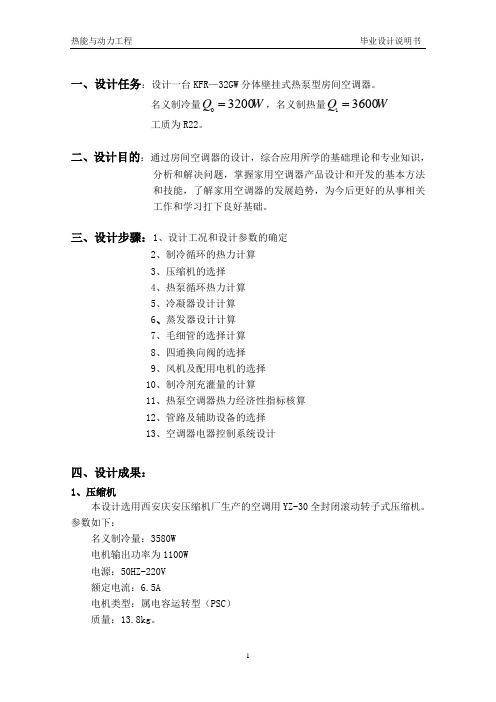
三、设计步骤:1、设计工况和设计参数的确定2、制冷循环的热力计算3、压缩机的选择4、热泵循环热力计算5、冷凝器设计计算6、蒸发器设计计算7、毛细管的选择计算8、四通换向阀的选择9、风机及配用电机的选择 10、制冷剂充灌量的计算11、热泵空调器热力经济性指标核算 12、管路及辅助设备的选择 13、空调器电器控制系统设计四、设计成果:1、压缩机本设计选用西安庆安压缩机厂生产的空调用YZ-30全封闭滚动转子式压缩机。
参数如下:名义制冷量:3580W 电机输出功率为1100W 电源:50HZ-220V 额定电流:6.5A电机类型:属电容运转型(PSC ) 质量:13.8kg 。
其安装示意图如图3-1所示,其中标注的尺寸为H=286mm,M=237mm,L=237 mm,E=75mm,D=110.5mm。
图1 YZ系列空调用转子式压缩机安装示意图2、冷凝器本设计选用强迫对流空冷式冷凝器。
其结构示意图如图2所示。
参数如下:传热管:紫铜管,mmφmm5.010⨯翅片: 厚度mm.0,波纹型整张铝制套片15节距:mm2迎风面管心距mm=S251管簇排列采用正三角形叉排冷凝器长:500mm冷凝器宽:86.6mm冷凝器高:312.5mm空气流通方向上的管排数n:4迎风面上管排数N:12冷凝器传热系数:30.39W/m2.K图2 空冷式冷凝器主体结构示意图3、蒸发器本设计采用强制对流的直接蒸发式蒸发器。
结构与蒸发器相近。
参数如下:传热管:紫铜管,mm mm 5.010⨯φ 翅片: 厚度,连续整体式铝套片节距:mm 8.1迎风面管心距mm S 251= 管簇排列采用正三角形叉排 蒸发器长:550mm 蒸发器宽:43.3mm 蒸发器高:237.5mm空气流通方向上的管排数n:2 迎风面上管排数N :9 蒸发器分路数:3路蒸发器传热系数:44.41W/m 2.K 4、节流装置本设计选用毛细管作为节流装置。

热能的转换与利用热能学与能量利用的研究热能的转换与利用在现代社会中,热能是一种非常重要的能源形式,广泛应用于各个领域,如发电、供暖、工业生产等。
因此,研究热能学与能量利用已经成为人们关注的热点话题。
本文将介绍一些热能的转换和利用方式,并探讨热能学与能量利用的相关研究。
一、传统能源转换与利用1. 热力发电:通过燃烧煤、石油、天然气等化石燃料,将燃料中的化学能转化为热能,再利用热能驱动汽轮机发电。
这是传统能源转换中常见且高效的一种方式。
2. 供暖系统:利用燃烧器或热泵等设备,将热能转化为热水或热空气,为建筑物提供供暖需求。
这在冬季地区尤其重要,能够保证人们的舒适生活。
3. 工业生产:很多工业过程需要大量的热能支持,比如炼钢、制糖、炼油等。
通过燃烧或者其他方式,将热能输送到工业设备中,实现生产过程的高效进行。
二、可再生能源的转换与利用1. 太阳能光热发电:利用太阳能热能进行发电是一种环保且可持续发展的方式。
通过集热器将太阳辐射能转化为热能,再利用热能驱动蒸汽涡轮机发电。
2. 风力发电:风能是一种非常丰富的自然能源,可以通过风力发电机将风能转化为电能。
这种方式不仅无污染,而且风力资源广泛分布。
3. 生物质能利用:利用农作物秸秆、木屑、废弃物等生物质资源,通过燃烧或者厌氧发酵等方式,将生物质能转化为热能或发电。
这种方式不仅能有效利用农业废弃物,还能减少温室气体排放。
三、热能学与能量利用的研究1. 热能系统优化:热能转换与利用中,系统的设计和运行非常重要。
研究人员通过建立数学模型,优化参数设置和能量流动路径,以提高系统的能量利用效率。
2. 高效储能技术:热能的储存和利用是一项关键技术。
目前,研究人员正在寻找更高效的热能储存材料和技术,以便在需要时能够更好地利用储存的热能。
3. 新型能源转换技术:随着技术的进步,新型的能源转换技术也得到了广泛研究。
例如,研究人员正在开发利用纳米材料、光热化学反应等新技术来转换和利用热能。

International Conference on Advanced Electronic Science and Technology (AEST 2016) Design and analysis of the movable solar energy heatutilization systemZijian Chen1, Lian Zhang1,2,a and Jinlin Zhang11School of electrical and energy, Tianjin Sino-German University of AppliedSciences, Tianjin, China/2China Computer-Room Equipment Engineering CO.,LTD, Tianjin, ChinaAbstract. This paper describes the design of the movable solar energy heat utilization system.The data of the system can be monitored and output for testing and analysis. The system cansave 3386.4 kWh of electricity per year.It can be known that this system uses only two hours toheat water for daily life.The system equipped batteries can be widely used even without theelectric source.Keywords: movable; system design; solar energy heat utilization1 IntroductionThe technology of solar thermal utilization is early invented[1], and has been greatly developed and popularized in the world. In recent years, the research of solar thermal utilization is focused on the heat collector[2], system design[3-4] and so on. Considering these questions, this paper design the movable solar energy heat utilization system, the specific contents are as follows.2 System designThe design of the movable solar heat utilization system includes the appearance structure, the heat circulating and the electrical controlling.2.1 Appearance structureThe components of the appearance structure of the system arebased on figure 1 and table 1.The solar flat plate heat collector is mounted on the movable frame.The water tank is fixed in the movable frame. The rolling wheels are installed at the bottom of the movable frame.When the solar flat plate heat collector works, rays of the sunirradiating on the endothermic base,be absorbed and transformed into thermal energy of the water.In the actual environment, the simulated light source can be removed.This system has the ability of movingby rolling wheels, which greatly improves the environmental adaptability.a Correspondingauthor:****************Figure 1. The side view, bottom view andpositive view of the appearancestructureTable 1. The visible components of the appearance structureaccording to the figure 1Labels according to the figure 1 ComponentsLabels according tothe figure 1Components1 Solar flat plate heatcollector 6 Touchscreen2 Simulated light source 7 Controlcabinet3 Movable frame 8 On-off4 Water tank 9 Switch box,5 Rolling wheels2.2 Heat circulatingAccording to figure 2, we can clearly see that the heat circulating of the system belongs to the forced circulation[5]. The DC water pump drives water between the water tank and the solar flat plate heat collector[6]. The use of the electromagnetic valve is to injectcold water to the water tank when the water volume is insufficient. The ultrasonic heatmeter[7]measures the flow rate and the temperature of the waterviatwo different sensors, and then calculates the thermal energyby a series of integral calculation. The liquid level sensorconverted the static pressureinto standard electric signal.Driven by the pumpto the collector,the cold water flowedout of the water tank.After absorbing the thermal energy of light, itis converted into hot waterand returnedto the water tank. This process forms a cycle that will achieve the purpose of heating the water continuously. The water from external water sourcecan is injected into the water tankthrough the inlet in the case of open the electromagnetic valve.The hot water can be used when opening the manual valve. Theelectric auxiliary heater can heat water in the absence of light. The data from the heat meter and the liquid level sensor are transmitted to the I/O controlboardfor controlling the pump, the electromagnetic valve and the electric auxiliary heater.Detailed design refers to figure 2 and table 2.Figure 2. The schematic of the heat circulatingTable 2. The components of the heat circulating according to the figure 2Labels according to the figure 2 ComponentsLabelsaccording tothe figure 2Components1 Solar flat plate heatcollector 7 Electromagneticvalve2 Ultrasonic heat meter 8 Exhaust port3 Drainage terminal 9 Water inlet4 Water outlet 10 DC water pump5 Liquid level sensor 11 Electric auxiliaryheater6 External water source2.3 Electrical controllingAC220V is converted into DC 24V by rectifier and transformer. The AC contactorcontrolsthe heater, and two electric relays controlthe pump and the electromagnetic valve respectively. Since M-Bus of the ultrasonic heat meter is not coupled with RS485 protocol of theI/O control board, the conversionmoduleneed toconvertthe data[8]. The I/O control boardincludes CPU, ports, interface,communication chips, and all kinds of conversion chips.In the electrical controlling circuit, 220V ACcan be suppliedforlight source, the contactor and the heater.It also can be converted to 24V DC, whichcan be supplied for the pump, the electromagnetic valve, the relays, the heat meter, the conversion module, the liquid level sensor, the touch screen and I/Oboard. The data of the conversion module and the data of the touch screen are communicated to the COM interface of the I/O board. The liquid level sensor data are input to the analog input (AI) port of the I/O board, and then the I/O board outputs the signal through the digital output (DO) ports tothe contactor and the relays.The I/O board can automatically control the relevant output signals according to the obtained data. Above working principle are basedon figure 3 and table 3. It is worth mentioning that thelight source and the heater depend on the 220V AC power supply, but the other components of the electrical controllingonly depend on the 24V DC power supply. So the system equipped batteries can be widely used even without the electric source.Figure 3. The electrical schematic of the systemTable 3. The components of the electrical controlling according to the figure 5Labels according to the figure 3 ComponentsLabels according tothe figure 3Components1 Rectifier 10 I/O control board2 Transformer 11 Liquid level sensor3 Ultrasonic heatmeter 12 Electric auxiliaryheater4 Air switches 13 Touch screen5 AC contactor 14 DC water pump6 On-off 15 Electromagneticvalve7Electric relays 16 Pilot lamp8 L,N 220V AC9 Conversionmodule24+,0- 24V DC3 System testing and analysisThe monitoring and controlling of the system relieson thetouchscreen. Users can monitor the automatic state, and also can control the manualstate.Meanwhile the real-time data and historical data such as temperature, thermal energy, rate of flow and power of the system can be collected and downloaded. Figure 4 is the experimentaldatacollected by the touch screen. The temperature and thermal energyof the system can be acquired in working condition.It can be known that this system uses only two hours to heat water for daily life.Figure 4.Temperature and thermal energy of the system in working condition.The thermalenergy of the system is about 8.35kWhaccording the data. The energy saving can be calculatedaccording to Eq. (1):ηE Q =∆ (1)Where:E= Theenergy of each heat utilization system, kWh; ΔQ = The energy saving of the system, kWh;η= The efficiency of the electric water heater, %;Taking into account η is roughly90%,the energy savingis9.28 kWh. The system can save 3386.4 kWh of electricity per year.4 ConclusionThe main features of this system are as follows.(i)The system can be used for the outdoor application of daily life in backward areas or lonely islands and the indoor teaching and training of energy specialty.(ii)The system has the function of data collectionandenergyconsumptionanalysis. The system can save 3386.4 kWh of electricity per year.It can be known that this system uses only two hours to heat water for daily life.(iii)The system equipped batteries can be widely used even without the electric source.AcknowledgmentsThis work was supported by the Science Fund of Tianjin Urban and Rural Construction Commission (Grant No. 2014-34) and Tianjin Higher Education Science and Technology Fund Planning Project (Project No. 20140426).References1. D.W. Coxon and T.P. Gates, Solar heat air system,U. S. Pantent,4,203,424, 1980-5-202.J.F.Lu and J.Ding, Heat transfer performance and exergetic optimization for solar receiver pipe,Renewable Energy, 1477–1483,35(2010)3.L.Zhang andY.F.Zhang, Research on Energy Saving Potential for Dedicated Ventilation SystemsBased on Heat Recovery Technology. Energies,4261-4280, 7,(2014)4.L.Zhang and Y.F.Zhang, Research on Heat Recovery Technology for Reducing the EnergyConsumption of Dedicated Ventilation Systems: An Application to the Operating Model of a Laboratory, Energies, 24,9,(2016)5. C.S.Lin and M.L.Lin, Development and applications of a fuzzy controller for a forced circulationsolar water heater system, Journal of Scientific & Industrial Research,Vol. 69, 7,(2010), pp. 537-5426.T. BERGENEandO. M. LOVVIK, Model calculations on a flat-plate solar heat collector withintegrated solar cells, Solar Energy, Vol. 55, No. 6,(1995), pp. 453-4627.W.L.Wang and C.C.Huang, The study of ultrasonic heat meter straight pipe length based on theCFD, 2nd International Conference on Machinery, Materials Engineering, Chemical Engineering and Biotechnology, (2015)8.L.BaiandM.Liu,Research on the detecting system of distributed nodes based on RS-485 bus,International Conference on Educational & Network Technology,422 – 425,(2010)。

《热能转换》作业设计方案一、设计背景:热能转换是物理学中一个重要的观点,涉及到热能的传递、转化和利用。
通过本次作业设计,旨在帮助学生深入理解热能转换的原理和应用,提高他们的实验操作能力和科学素养。
二、设计目标:1.了解热能的基本观点和热能转换的原理;2.掌握热能转换的实验方法和技巧;3.培养学生观察、实验设计和数据分析能力;4.提高学生的团队合作和表达能力。
三、设计内容:1.实验一:热能传递实验实验目标:通过观察不同材料的导热性能,了解热能在不同材料中的传递方式。
实验步骤:(1)准备一块金属板和一块塑料板,用手触摸板材的不同部位,感受温度差别;(2)在板材上分别放置一个加热器,观察加热器对板材的影响;(3)记录板材不同部位的温度变化,比较金属板和塑料板的导热性能。
2.实验二:热能转化实验实验目标:通过热能转换装置,将热能转化为机械能,探讨热能转换的原理。
实验步骤:(1)搭建热能转换装置,包括加热器、发电机和转动装置;(2)给加热器加热,观察发电机的转动情况;(3)测量发电机输出的电能和机械能,分析热能转换的效率。
3.实验三:热能利用实验实验目标:通过利用太阳能和地热能,探讨热能的可更生利用方式。
实验步骤:(1)搭建太阳能和地热能利用装置,分别将太阳能和地热能转化为热能;(2)观察收集到的热能,比较两种能源的利用效率;(3)设计并制作一个简单的热能利用器具,实现热能的再利用。
四、作业要求:1.学生分组进行实验,每组成员分工合作,完成实验记录和数据分析;2.每组需提交一份实验报告,包括实验目标、步骤、结果和结论;3.在教室上进行实验效果展示和交流,加深对热能转换的理解;4.鼓励学生提出问题和建议,增进学生的思维拓展和创新能力。
五、评判标准:1.实验记录和报告的完备性和准确性;2.实验设计和数据分析的合理性和深度;3.团队合作和表达能力的发挥;4.对热能转换原理和应用的理解和掌握水平。
六、教师指导和辅导:1.提供实验器械和资料支持;2.指导学生进行实验操作和数据记录;3.组织教室讨论和实验展示,引导学生深入思考和交流。

物理实践热能的转换与利用热能是指物体由于热而具有的能量。
在物理实践中,热能的转换与利用一直都是一个重要的课题。
热能的转换和利用涉及到许多物理原理和技术应用,对于能源的管理和利用具有重要意义。
本文将重点介绍热能的转换与利用的原理、方法和应用。
一、热能的转换原理热能的转换是指将热能转化为其他形式的能量,如机械能、电能等。
热能转换的原理基于热力学定律,主要包括以下几种方式:1. 热能转化为机械能:这是最常见的热能转换方式,通过利用热能使物体产生热胀冷缩、热气流推动等现象,将热能转化为机械能。
例如,蒸汽机利用水的沸腾产生高温高压的蒸汽,然后通过蒸汽推动活塞运动,实现热能转换为机械能。
2. 热能转化为电能:利用热能产生的温差效应可以将热能转化为电能。
热电效应是指在两种不同导电性质的材料之间,由于温度差异而产生的电势差。
热电发电机利用这一原理,将热量转化为电能。
例如,太阳能发电就是利用太阳辐射的热能转换为电能的过程。
3. 热能转化为化学能:化学电池是一种将热能转化为化学能的设备。
通过在化学反应中释放热能,并将其转化为电能。
例如,燃料电池就是一种将燃料的热能转换为电能的装置。
4. 热能转化为光能:光伏效应是指当光照射到某些材料上时,会产生电压差和电流的现象。
利用光伏效应,可以将太阳辐射的热能转化为光能。
太阳能电池板就是一种将太阳能转换为可利用电能的器件。
二、热能的利用方法及应用热能的利用是指将热能用于人类生产和生活的过程。
热能的利用方法多种多样,根据不同的需求和场合选择不同的方式。
以下将介绍几种常见的热能利用方法及其应用场景:1. 热能利用于供暖:利用热能进行供暖是一种常见的利用方式。
通过燃煤、燃气、太阳能等方式产生热能,利用热水、蒸汽等形式将热能传输到室内,使室内保持温暖。
这种方式主要应用于冬季的供暖需求。
2. 热能利用于发电:利用热能进行发电是一种重要的热能利用方式。
通过燃煤、核能、太阳能等方式产生高温高压的蒸汽,然后利用蒸汽驱动汽轮机转动发电机,将热能转化为电能。
热能转化与利用设计说明书新热能转化与利用设计说明书新热能转换与利用设计说明书学院:能源与环境专业:热能09-3班姓名:王晓娟学号:0962126345 目录设计任书............................................................ 3 设计方案............................................................ 5 设计流程............................................................ 6 设计参数............................................................ 7 计算部分............................................................10 火用计算............................................................16 结论附表 (17)设计感想 (19)内蒙古科技大学课程设计任务书课程名称:热能转换与利用课程设计设计题目:1167吨/日20号钢(钢种)轧钢工艺后续钢材冷却系统能量回收与设备设计指导教师:伍永福时间:2011/2012第二学期18-19周一、教学要求1、提高学生的设计动手和协调共事能力2、掌握能量转换的基本规律3、掌握能量平衡的分析方法4、掌握换热器设计计算的基本步骤和规律,能完成换热规律与工艺匹配的要求。
二、设计资料及参数1、冷却线工艺平面布置图2、产量及钢种产量:1167t 钢种:含碳量为0.16%的20号钢3、工艺冷却要求:吐丝温度是控制相变开始温度的关键参数。
对于斯太尔摩冷却法来说,一般是根据钢种和用途的不同将吐丝温度控制在750℃—900℃范围内。
内蒙古科技大学热能转换与利用课程设计说明书学院: 能源与环境学院专业:热能与动力工程班级:热动09-1班姓名:赵胜学号: 0962126103指导老师:陈伟鹏目录第一章热风炉热工计算 (3)1.1热风炉燃烧计算 (3)1.2热风炉热平衡计算 (5)1.3热风炉设计参数确定 (8)第二章热风炉结构设计 (8)2.1设计原则 (8)2.2 工程设计内容及技术特点 (9)2.2.1设计内容 (9)2.2.2 技术特点 (9)2.3结构性能参数确定 (9)2.4蓄热室格子砖选择 (12)2.5热风炉管道系统及烟囱 (13)2.5.1顶燃式热风炉煤气主管包括: (13)2.5.2顶燃式热风炉空气主管包括: (14)2.5.3顶燃式热风炉烟气主管包括: (15)2.5.4顶燃式热风炉冷风主管道包括: (15)2.5.5顶燃式热风炉热风主管道包括: (16)2.6 热风炉附属设备和设施 (16)2.7热风炉基础设计 (18)2.7.1 热风炉炉壳 (18)2.7.2 热风炉区框架及平台(包括吊车梁) (18)第三章热风炉用耐火材料的选择 (18)3.1耐火材料的定义与性能 (18)3.2热风炉耐火材料的选择 (19)参考文献 (21)第一章热风炉热工计算1.1热风炉燃烧计算燃烧计算采用高焦炉混合煤气做热风炉燃料,并为完全燃烧。
已知煤气化验成分见表1-1。
表1-1 煤气成分表项目 CH4 C2H6 OH2H2CO CO2N2O2∑含量% 8.5 0.7 2.3 20.4 19.7 8.6 39.5 0.3 100.00热风炉前煤气预热后温度为300℃,空气预热温度为300℃,干法除尘。
发生炉利用系数为2.3t/m3d,风量为2000m3/min,t热风=1100℃,t冷风=20℃,η热=90%。
热风炉工作制度为两烧一送制,一个工作周期T=2.25h,送风期Tf=0.75h,燃烧期Tr=1.4h,换炉时间ΔT=0.1h,出炉烟气温度tg2=350℃,环境温度te=20℃。
《热能转换》作业设计方案第一课时一、教学目标:1. 了解热能与其他形式能量之间的转换关系;2. 掌握各种热能转换原理和过程;3. 能够运用所学知识解决实际问题;4. 培养学生的实验设计和探究能力。
二、教学内容:1. 热能的概念及特性;2. 热传递的方式及热传递规律;3. 热力学第一定律和第二定律;4. 热能转换的实例分析。
三、教学重点:1. 热能的定义与特性;2. 热传递的方式及规律;3. 热力学定律的理解与应用。
四、教学难点:1. 热能与其他形式能量之间的转换过程;2. 热力学定律的精确描述与推导。
五、教学方法:1. 讲授与实践相结合;2. 实验教学;3. 讨论交流。
六、教学过程设计:1. 导入:通过介绍热能转换的一些实例引入课题;2. 知识讲授:讲解热能的概念、热传递方式及热力学定律;3. 实验设计:设计一些简单的实验,让学生探究热能转换过程;4. 讨论交流:让学生分享实验结果,讨论热能转换的应用;5. 总结反思:总结课程内容,引导学生思考热能转换在生活中的应用。
七、作业设计:1. 作业一:设计一个简单的实验,验证热传递的方式,要求学生详细记录实验过程及结果,并总结实验规律;2. 作业二:热力学第一定律和第二定律理论分析题,要求学生分析热力学定律在热能转换中的应用;3. 作业三:热能转换实例分析,要求学生选择一个实际的热能转换例子进行分析,并撰写实验报告。
八、自主探究:鼓励学生自主探究热能转换的更多实例,提出新的研究问题,并在小组内展开合作研究。
九、总结展望:通过本次学习,学生将深入了解热能转换的原理和应用,培养学生的实验设计和探究能力,为将来的学习和科研打下坚实基础。
同时,本次作业设计也将激发学生对热能转换的兴趣,提高他们的实践能力和综合分析能力。
希望通过这次作业设计,学生能够更深入地理解热能转换的重要性,同时能够运用所学知识解决实际问题,为未来的学习和生活做好准备。
第二课时一、背景介绍热能转换是物理学中的一个重要概念,也是日常生活中常见的现象。
热能转换与利用设计说明书学院:能源与环境专业:热能09-3班姓名:王晓娟学号:0962126345目录设计任书 (3)设计方案 (5)设计流程 (6)设计参数 (7)计算部分 (10)火用计算 (16)结论附表 (17)设计感想 (19)内蒙古科技大学课程设计任务书课程名称:热能转换与利用课程设计设计题目:1167吨/日20号钢(钢种)轧钢工艺后续钢材冷却系统能量回收与设备设计指导教师:伍永福时间:2011/2012第二学期18-19周一、教学要求1、提高学生的设计动手和协调共事能力2、掌握能量转换的基本规律3、掌握能量平衡的分析方法4、掌握换热器设计计算的基本步骤和规律,能完成换热规律与工艺匹配的要求。
二、设计资料及参数1、冷却线工艺平面布置图2、产量及钢种产量:1167t钢种:含碳量为0.16%的20号钢3、工艺冷却要求:吐丝温度是控制相变开始温度的关键参数。
对于斯太尔摩冷却法来说,一般是根据钢种和用途的不同将吐丝温度控制在750℃—900℃范围内。
斯太尔摩冷却法的相变过程中,冷却速度控制靠风机的风量和运输机的速度,而这两个参数的确定依赖于该钢种的CCT 曲线。
集卷温度取决于相变结束后的冷却过程,为保证产品性能和避免集卷后的高温氧化及劳动环境,一般来说要求在250℃以下集卷。
三、设计要求及成果1、说明书和计算书各一份。
1)计算系统各部分能量分布,分析能量利用情况。
2)计算系统各部分的用,分析用利用情况。
3)根据能量分布和利用分布情况设计一套换热装置,满足换热要求。
2、能流总图手绘图(1#图纸一张)图纸包括系统能流图及换热器的结构图。
四、进度安排1、根据给定的参数或工程具体要求,收集和查阅资料(二天)2、初步设计合理的能量转化的热工设备和热力系统,绘出能流图(四天)3、评介热力系统和优化设计方案,选取最佳方案(三天)4、编写技术设计书(一天)五、评分标准1、能按要求及时完成设计任务,工作量饱满,计算详细,说明理由充分条例清晰,绘图层次分明线型合理,手绘图线型一致工整,评分等级为优。
2、能按要求及时完成设计任务,计算详细,说明理由基本充分条例基本清晰,绘图层次分明线型合理,手绘图工整,评分等级为良。
3、能基本按要求及时完成设计任务,计算完整,说明清楚,绘图基本合理,手绘图工整,评分等级为及格。
4、不能按要求及时完成设计任务,工作量任务量特少。
评分等级为不及格。
六、建议参考资料1.《热能转换余利用》汤学忠冶金工业出版社,2002年3月。
2.《系统节能基础》,陆钟武主编,冶金工业出版社,1999年10月;3.《冶金热能工程导论》,陆钟武主编,东北工学院出版社,1997年3月;4. 《换热器设计手册》,钱颂文等译,中国石化出版社,2004年1月5. 轧钢基础知识(,冶金工业出版社),出版日期:2005-116. 实用轧钢技术手册杨宗毅7. 高速线材生产, 冶金工业出版社, 2005-0420 #钢轧钢工艺后续钢材冷却系统能量回收与设备设计一、设计方案1、冷却工艺布置图2、设计背景:线材在出吐丝机到集卷筒过程中经过斯太尔摩冷却线进行冷却,其冷却速度按CCT冷却曲线降温,热量散失比较大,现设计一种热能回收装置回收利用。
3、设计方案:现选用风罩空冷对其冷却回收热能,线材吐丝温度为865℃,冷却到常温25℃,空气从20℃进入风罩,以700℃出风罩,高温空气加以利用。
二、设计流程1、确定线材冷却前后的温度及空气加热前后的温度2、按等温降将冷却过程分成若干段3、根据线材日产量、冷却温差、平均比容得到日产热量4、依据3得到的热量假设完全被空气换热,算出理论空气量5、从CCT曲线上确定每段降温时间及总时间。
6、以冷却线长度和降温时间算得辊道速度和每段长度。
7、根据日产量得到每段线材质量及放热量Φ’8、已知线材参数得到换热面积A9、假设每段放热量由对流换热吸收,由以下流程计算:有公式:Re=u l/λ Nu=CRenPr1/3 h=λ×Nu/lΦ=hAΔt否设流速u→Re→Nu→h→Φ→Φ=Φ’?↓是流速u正确10、由流量、流速、辊道宽度确定风罩高度。
11、确定每段风罩高度。
12、计算空气出口温度13、计算总的热损失和火用效率。
三、设计参数已知钢材:20#钢线材冷却CCT曲线冷镦钢丝又称铆螺钢丝或冷顶锻钢丝, 主要用于制造螺栓、螺钉、螺柱、螺母和铆钉等紧固件, 近年来逐步扩大到电器、照相机、纺织器材、冷冻机等领域, 应用范围广。
采用冷镦的方法生产标准件, 变形速度快、变形程度大、变形不均匀、尺寸精度要求高, 因此冷镦钢丝用钢材首先必须有良好的塑性、尺寸精度和内在品质, 从冶炼到钢丝生产各环节必须严格控制工艺操作, 才能生产出品质稳定的钢丝。
鉴于冷镦钢具有的良好经济效益, 广泛的用途,新钢公司对冷镦钢SWRCH22A 进行了开发生产。
表1 SWRCH22A 成分控制一、设计条件: 钢种 SWRCH22A(R)二、冷却分段:t 比热容(kj/kg.k)冷却时间(s)第一段 880 830 50 0.688175 104.16第二段 830 780 50 0.665975 136.5第三段 780 730 50 0.6364 97.21第四段 730 680 50 0.6058 77.47第五段 680 630 50 0.5837 64.72 第六段 630 580 50 0.5668 55.44 第七段 580 530 50 0.5502 48.18 第八段 530 480 50 0.5353 42.22 第九段 480 430 50 0.5244 37.16 第十段 430 380 50 0.5157 32.74 总的冷却时间 t=695.78s三、计算产量、速度、风速等设管道长度:L=1速度:v= L/t=146.1138/695.78=0.21m/s设钢筋直径:d=6mm管道宽:b=2m钢筋之间的距离:l=4cm圈数:n=(146.1138-2)/0.04=3603圈线材密度:7850 kg/3M日产量:2*3.14*(0.006/2)2*3.14*3603*3600*24/695.78=623314.92kg风量:qm =cpm∆t(c1t1-c2t2)=0.587225*623314.92*(880-380) (668.4-30.15)=286741.9537m3每秒风量:286741.9537/3600*24=3.412kg/s第一段的计算长度:l=vt=0.21*32.74=6.8754m圈数:n=l1/l*n=6.8754/146.1138*3603=169.539 换热面积:A=πdnπD=3.14*2*169.539*3.14*0.006=20.059m2对钢锭:m1=7.214*32.74=236.186kgE=m1cp∆t=236.186*0.51565*50*1000=6089474.8E .=E /t 1=6089.4748/32.74=185.995对空气:进口温度:t 1=30℃ p r =0.703E ’=φ=hA t ∆H=185.995/63.8166[(380+430)/2-30]=7.57019 线材直径设为d=6mm , 线圈直径 D=2mt-=[(t 1+t 2)/2 +20]/2=212.5℃ 查附录5得出:λ=4.015N u =hd /λ=7.57019*0.006/4.015*0.01=1.131Re=(N u /0.6643pr )5.0=3.67469u 1=Rev /l 1=3.67469*63.808/21.8736=10.7203m /s空气出口温度:t 2=Φ/mCp+30=t ∆+30=3.31877*1000/236.186*1.06695+30=44℃线材总的放热量=日产量*线材平均比容*(880-830)=183013051949j第一段:第一段质量=冷却时间*每秒产量=32.74*7.214=236.196kg 第一段的段长=32.74*0.21=6.875m第一段线材质量=线材密度*线材体积=236.196kg第一段线材体积=1064.169*(0.006/2)*2*3.14159=0.03m3第一段线材理论放热量=每段线材的质量*线材比容*∆t=236.196*515.65*50=6089722.200j第一段线材理论热流量=第一段线材放热量/冷却时间=6089722.200/32.74=186002.511jh =线材直径*Nu*λ=0.006*Nu*λ=37.157Φ=h*每段线材面积*(347.5-30)=37.157*20.095*317.5=236645.675空气总质量=每秒供风量*32.74℃=2.843*32.74=93.087kg 空气总流量=总质量/密度=93.087/1.0165=91.576m3/s 空气每秒流量=91.576/32.74=2.797m3/s空气换热后的温度:=30℃+236645.675/(2.843+780)=136.707℃三、计算热损失及火用效率1、选用硅藻土转作为绝热材料体积密度:ρ=0.55g/cm3允许工作温度<900℃导热系数λ=0.093+0.24×10-3t2、热损失计算(1)分段均温第一段tpj=(25+85)÷2=55(2)外部温度设为20℃(3)内外温差Δt=55-20=35(4) λ=0.093+0.24×10-3×35=0.1062 W/(m2·k)(5)材料厚度设δ=0.2m(6)热流密度q=λ×Δt/δq=0.1062×55÷0.2=18.585w/m2(7)风罩表面积A=(2H+B)×lA=(2×0.029+4)×2.617=5.387m2(8)每段散热流量Φ=AqΦ=5.387×18.585=100.122W(9)总热损失Φ损=Φ1损+Φ2损+Φ3损+……+Φ13损Φ损=1479664.782w(10)总热流量Φ热=Φ1热+Φ2热+Φ3热+……+Φ13热Φ热=2099465.417w(10)损失率η损=Φ损/Φ热×100%η损=1479664.782÷6133516.979×100%=24.12%五、火用计算将风罩出口的热空气把吹入热风炉的空气预热,热风炉进口风温为300℃,,风罩出口风温为699.89℃。
如果不考虑热损失,则假设热风能将一定质量的冷风加热到300℃,最终与其一起吹入热风炉。
ηc=1-(To/T)ηc%=1-(300+273)/(699.89+273)=41.109%初步计算得出热风的火用效率大致为41.109%,该热能回收装置将线材冷却放出的热量回收利用到加热冷空气并一起吹入热风炉中。