德国科隆krohne金属转子流量计H250系列英文说明书
- 格式:pdf
- 大小:2.63 MB
- 文档页数:88
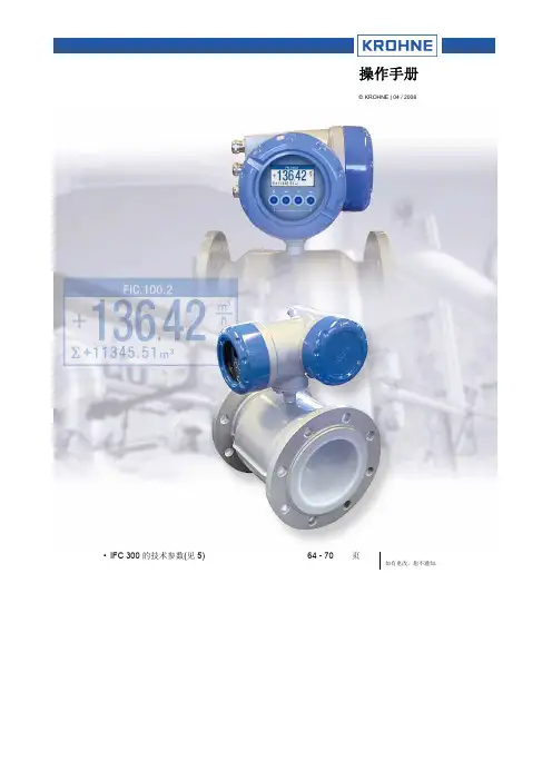
涡街流量计电子版本: ER 2.0.0_OPTISWIRL 4200快速启动© KROHNE 08/2017 - 4004294402 - QS OPTISWIRL 4200 R03 zh内容2 08/2017 - 4004294402 - QS OPTISWIRL 4200 R03 zh1 安全须知32 安装42.1 用途.....................................................................42.2 供货范围.................................................................62.3 存储.....................................................................62.4 运输.....................................................................72.5 安装条件.. (8)2.5.1 测量液体时应严禁的安装......................................................92.5.2 测量蒸汽和气体时应严禁的安装...............................................102.5.3 带控制阀的管线.............................................................102.5.4 推荐安装位置 (11)2.6 最小进口直管段..........................................................122.7 最小出口直管段..........................................................132.8 整流器..................................................................132.9 安装.. (14)2.9.1 安装注意事项...............................................................142.9.2 夹持型仪表的安装...........................................................152.9.3 法兰型仪表的安装...........................................................162.9.4 分体型现场外壳的安装.......................................................172.10 隔热层.................................................................182.11 转动机壳...............................................................192.12 旋转显示板. (20)3 电气连接213.1 安全须知................................................................213.2 连接信号转换器..........................................................223.3 电气连接. (23)3.3.1 电源.......................................................................233.3.2 电流输出...................................................................233.3.3 电流输入...................................................................243.3.4 二进制输出.................................................................243.3.5 限位开关输出...............................................................253.3.6 脉冲输出 / 频率输出........................................................273.3.7 状态输出...................................................................283.4 分体型的接线............................................................283.5 接地连接................................................................303.6 防护等级. (31)13 08/2017 - 4004294402 - QS OPTISWIRL 4200 R03 zh 警告与符号使用操作• 此符号标注出所有的操作提示,操作人员必须按规定顺序进行操作。
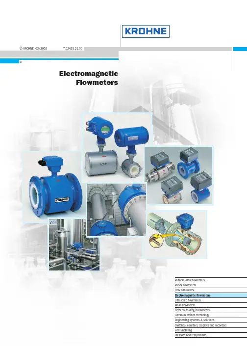
©KROHNE 03/20027.02425.21.00GRElectromagneticFlowmetersVariable area flowmetersVortex flowmetersFlow controllersElectromagnetic flowmetersUltrasonic flowmetersMass flowmetersLevel measuring instrumentsCommunications technologyEngineering systems & solutionsSwitches,counters,displays and recordersHeat meteringPressure and temperatureApplicationKROHNE electromagnetic flowmeters are to be found in many industrial sectors and applications.Just a small selection:G Chemical industry G Water and wastewaterGHydraulic transport,liquid products with up to 50% solids content G Paper and woodpulp production G Pharmaceutical G Food and beveragesG Filling and dispensing processes G Highly abrasive slurriesG High-pressure industrial processes GPartially filled pipelinesand many,many other applications in other industriesFIT and FORGET !All electromagnetic flowmeters are delivered ready for operation.Install the flowmeter in the pipeline,make the electrical connection,that's it.Always one step ahead with KROHNEThis highly accurate measurement technology is available with integrally or remote mounted converter,some with measuring errors of less than 0.2% of the measured value.The primary head is installed in the pipeline,while the signal converter for signal processing is remote mounted in a field housing or 19" plug-in unit.In the integral system,the signal converter is mounted in a housing with high protection category directly on the primary head.With meter sizes of DN2.5 - 3000 / 1/10" - 120",measurements can be carried out from 2l/h to 300 000m3/hand more.Most of the devices are approved for use in hazardous locations.Various materials are available for the measuring tube,liner and electrodes of the flowmeters for most applications. Electromagnetic flowmetersProduction and calibrationAll electromagnetic flowmeters from KROHNE meet the requirements of CE directives and EMC guidelines.Fabrication and production shops are certified to ISO 9001.At KROHNE,all electromagnetic flowmeters are calibrated by direct comparison of volumes,the most accurate calibration method of all.The KROHNE calibration rigs are the world's biggest and most accurate,and are accredited to EN17 025.Measurement uncertainty is less than 0.013% of themeasured value for meter sizes up to DN 3000 / 120" and above.7Electromagnetic flowmeters >0.05 µS /c m >5 µS /c m >20 µS /c m >50 µS /c mD N 2.5,4,6 1/10”,1/6”,1/4”D N 10 3/8”D N 32 11/2”Signal converterDatenblätterF l a n g e c o n n e c t i o n s F l a n g e l e s s ‘s a n d w i c h ’d e s i g n C h e m i c a l s W a t e r a n d s e w a g e P a r t i a l l y f i l l e d p i p e s P h a r m a c e u t i c a l s ,s a n i t a r y B a t c h i n g (1-10s )V e r y a b r a s i v e s l u r r i e s H i g h p r e s s u r e 2- o r 2 x 2-w i r e s y s t e mG e n e r a l p u r p o s e S a n i t a r y c o n n e c t i o n s H A R T ®/R S 485 (s t a n d a r d )P r o f i b u s P A H A R T ®/R S 485 (o p t i o n )H A R T ® (o p t i o n )O t h e r s o n r e q u e s t m Ao u t p u t ,2 w i r e c o n n e c t i o n ≤3 W ≤5 V A / ≤4.5 W ≤10 V A / ≤8 W ≤15 V A / ≤15 W ≤50 V A 2o r 2 x 2-w i r e s y s t e m 24,48,100 – 240 V A C ,48– 63 H z 24 V D C 24 V A C / D C 100 – 230 V A C ,48 –63 H z L i q u i d s ,p a s t e s S l u d g e a n d s l u r r i e s % s o l i d s /v o l u m e ≤3%S l u d g e a n d s l u r r i e s % s o l i d s /v o l u m e ≤5%S l u d g e a n d s l u r r i e s % s o l i d s /v o l u m e ≤30%P u l s a t i n g f l o w ,< 200 p u l s e s /m i n B a t c h i n g p r o c e s s > 1.5 s P a p e r a n d p u l p H y d r a u l i c t r a n s p o r t (o r e d r e s s i n g )o n l y I F C 090 K -C A P C a p a c i t i v e s i g n a l p i c k u p F ou n d a t i o n F i e l d B u s F A D N 251”D N 40 11/2”D N 502”D N 803”D N 1004”D N 1255”D N 1506”D N 2008”D N 25010”D N 30012”≤D N 1800≤72”≤D N 3000≤120”I S O f i t t i n g l e n g t h o n l y I F C 110 P F a n d I F C 210 E -P F P a r t i a l l y f i l l e d p i p e s ,AQUAFLUXECOFLUX 1000ALTOFLUX 2000ALTOFLUX 4000PROFIFLUX 5000VARIFLUX 6000ALTOFLUX 2W 2 wireBATCHFLUXCAPAFLUXTIDALFLUX partially filledALTOFLUX IFS 2005 FALTOFLUX IFS 4005 FALTOFLUX M 900IFC 010 K,FIFC 020 K,F ,EIFC 040 K 2 wireIFC 090 K,F IFC 090 K-CAP IFC 110 F IFC 110 PFIFC 210 E IFC 210 E-PFSC 150 FBatchflux IFC 012 KElectrical conductivitySizesConnectionsApplications (examples)Flow measurements (examples)Power supply Power consuptionInterfacesIFM 1080 KG Flangeless versionG Rugged measuring tube withstainless steel reinforced 080 KG Flanged connectionsG Steel housingµP-signal converter in plasticsIFM 4080 KG Flanged connectionsG Steel housingTeflon® PFA liner,reinforced withIFM 5080 KG Flangeless versionG Stainless steel housing The only precision flowmeter IFM 6080 KG Various sanitary/flangedconnectionsStainless steel housingG Precision flowmeterG With capacitive signal pickup(electrodes not in contact withG Flangeless versionG Rugged measuring tube withstainless steel reinforced G Flanged connectionsG Steel housingG Liner of Polypropylene,NSF-G Flanged connectionsG Steel housingG Teflon® PFA liner,reinforced withG Flangeless (sandwich) designG Stainless steel housingG The only precision flowmeter with G Flanged connectionsG Steel housingG Measuring tube made of Al2O3G Various sanitary/flanged connec-tions,stainless steel housingG FDA approved Teflon® PFA liner,G Designed for partially filled pipelinesG Excellent measuring accuracy,for low levels,through the integratedG IFC 010 K/IFC 020 K of integral design G IFC 010 F/IFC 020 F in field housing G IFC 020 E 19”plug-in version.G IFC 090 K of integral designG IFC 090 F in field housingG Signal processing by microprocessor,G Signal converter in field housingG Signal processing by microprocessor,outstanding interference rejection,G Signal converter in field housing for wall mounting G Signal processing by microprocessor,outstanding interference rejection,T o w e r h e i g h t 43 m e q u i v a l e n t t o 141 f t / n e t v o l u m e 350000 l i t r e s e q u i v a l e n t t o 95000 U S G a lPrecisionLM28 precision level switches control the flow volume and various computer-aided volume totalizersQmInlet run ≥10 ×DN (DN = meter size)©G The world’s largest and most accurate calibration rigGCalibration of flowmeters up to DN 3000 / 120”GCalibration by direct comparison of volumes,altogether the most accurate method GComparison measurements with so-called master meters are much less accurate and cannot be verifiedGThe volume measurement standards ofKROHNE calibration rigs have been calibrated by NMI,the Netherlands Standards Institute.Measurement uncertainty is less than 0.013% of the measured value.GKROHNE Altometer calibration rigs are accredited in conformity with EN 17 025.GCalibration accuracy is better than 99.97% of the measured value.GThe error of measurement of the calibration rigs is better by a factor of 10 than theaccuracy data of the flowmeter being tested.GAll flowmeters are calibrated underreference conditions,similar to EN 29 104.GAll calibration data are genuine and verifiable; documented in writing in the calibration reports,which are supplied together with each KROHNE flowmeter.An example is shown on the right.E r r o r o f m e a s u r e m e n t [% o f m e a s u r e d v a l u e ]Flow rate [m 3/h]0,50,402000400060008000100000,30,20,10,0-0,1-0,2-0,3-0,4-0,5+ 0.03%Accuracy inspires confidenceAt this flowrate,a typical public swimming-pool can be filled in less than 1 minute.Inaccuracy is less than 0.013% in terms of volume and less than 0.26 mm in terms of filling level (equal to the thickness of a single hair),based on an average pool depth of 2 metres.Flowmeters up to DN 3000/120”creates theKROHNE standardOutlet run ≥2 ×DN (DN =meter size)Volume flow rate Q max = 40 000 m 3/h= 11 m 3/sMeasuring Principle 3.1The induced voltage signal is picked up either by two measuring elec-trodes in conductive contact with the medium or indirectly bycapacitive coupling.A signal converter amplifies the signal and convertsit into a standard analog signal (e.g.4 to 20 mA) and a frequencysignal (e.g.1 pulse for every US gallon or cubic metre of mediumflowing through the measuring tube).To ensure that the voltage is not short-circuited by the pipe wall,themeasuring tube is made of an electrically insulating material or fittedwith an insulating liner.Measurement is largely independent of the flow profile and other prop-erties of the medium,such as pressure,temperature,viscosity,density,consistency,electrical conductivity,and electrode contamination.Measuring systemsThe electromagnetic flowmeter consists of a primary head,that isinstalled in the pipeline,and a signal converter.The compact design has the signal converter mounted directly on theprimary head.For systems with pulsed d.c.field the primary head field coils whichgenerate the magnetic field are energized by a pulsed direct currentfrom the signal converter.The measuring signal is a squarewave voltage of the same frequency.These systems feature extremely small measuring errors. Electromagnetic flowmeters measure the volume flow of electricallyconductive liquids and slurries.Measuring principleAn electric conductor,in this case the electrically conductive medium,passes through a magnetic field.The voltage U induced in this mediumis directly proportional to the mean flow velocity v.Magnetic inductionB (magnetic field strength) and the distance between electrodes D(nominal pipe diameter) are constant.K instrument constantB magnetic field strengthv mean flow velocityD electrode spacingThe volumetric flow rate qv can be calculated according toTherefore:q v=U x D xπ(4)K x B4The reducing angle (α) should not exceed 8°(equivalent to α/2 = 4°),otherwise measuring accuracy may be affected.If the reducing angle is greater,a straight inlet section must be fitted between reducing socket and primary head.Expanding sectionPressure Loss CalculationFor the expanding section,the optimum angle of expansion is α= 8°.ζat α= 8°d1/d2 1.2 1.3 1.4 1.5 1.6 1.7 1.8 1.9 2.0ζ10.0180.0230.02550.0280.030.03080.03150.03230.0332Recommendations for installationSelection of meter sizeThe size of primary head should if possible be selected to provide a velocity of 2 to 3m/s or 6 to 9ft/sec.for the full-scale range. Minimum full-scale range is 0.5m/s or 1.5ft/sec.,maximum is 10 or 11m/s or 30 or 33ft/sec.,depending on flowmeter type.For fluids with a solids content,the velocity should be between 3 and 5m/s or 9 and 15ft/s to prevent deposits and minimize abrasion.Exact determination of flow velocityFor range setting purposes,the exact flow velocity can be determined using the flow table for each nominal pipe width.Example: v in m/sNominal pipe diameter DN150Desired measuring range200m3/hFrom the table we obtain for the flow velocity of 1m/sa flow rate of 63.617m3/h at DN150; for 200m3/hthe flow velocity v is:Example: v in ft/sNominal pipe diameter6”Desired measuring range1000 US GPMFrom the table we obtain for the flow velocity of 1ft/sa flow rate of 88.128 US GPM at 6”meter size;for 1000 US GPM the flow velocity v is:Flow tablesv = 1m/sMeter size Flow rate Meter size Flow rate DN mm m3/h DN mm m3/h2.50.017671250176.71 40.0452********.47 60.10179350346.36 100.28274400452.39 150.63617500706.86 20 1.131********.9 25 1.76717001385.4 32 2.89538001809.6 40 4.52399002209.2 507.068610002827.4 6511.94612004071.5 8018.09614005541.8 10028.27416007238.2 12544.17918009160.9 15063.617200011310 200113.10v = 1ft/sMeter size Flow rate Meter size Flow rate inch US GMP inch US GMP1/100.024********.801/80.03825012352.511/40.1530014479.813/80.3442516626.69 1/20.6120020979.21 3/4 1.3770241410.1 1 2.4480281919.211/4 3.8250322506.8 11/2 5.5080363172.6 29.7921403916.8 21/215.300485640.2 322.032567677.0 439.1686410027 561.2007212691 688.1288015667 8156.67Protection classes to IEC 529/EN 60529。
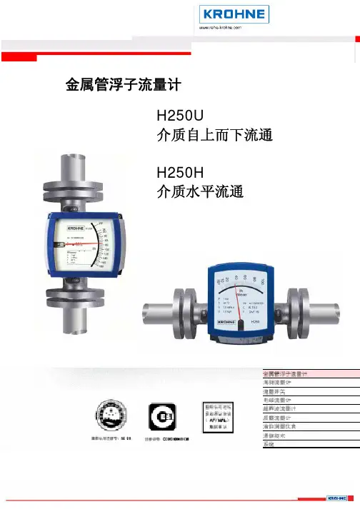
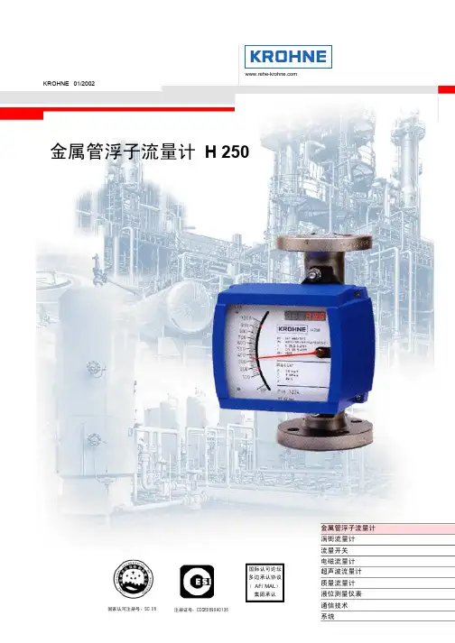
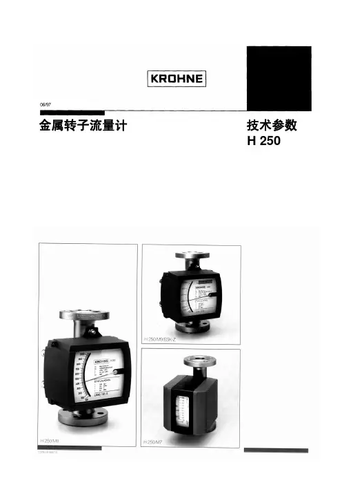
金属管浮子流量计H250U介质自上而下流通 H250H介质水平流通1:简述H250HU是全金属结构,可带无磁滞后、无任何传动机构变送器,可现场安装气阻尼装置的模块化金属管水平安装垂直上进下出式浮子流量计。
基于模块化设计,远传信号输出,开关信号输出,累计量显示,HART协议执行,Profibus-PA总线,可以全部根据用户需求即时安装与使用。
始于1990年的生产与应用经验,为您提供尽善尽美的服务。
H250已经广泛应用于石油,化工,冶金,电力,食品,制药,造纸等行业的液体、气体、蒸汽介质的测量与过程控制。
2:H250HU结构基于测量原理设计的H250浮子流量计主要由两部分组成,测量管与指示器。
RR1 1Cr18Ni9Ti不锈钢测量管RR 316L不锈钢测量管M9,M10指示器ESK 4-20mA二线制变送器ESK-Z 4-20mA二线制变送器带现场累计显示ESK3-PA Profibus PA变送器K 开关信号传感器德国KROHNE公司80多年的设计与应用经验数据蕴藏在产品结构中。
2:优点z坚固、简洁、可靠设计z模块化、智能化指示器设计z一次成型测量锥管z X-射线探伤z短行程、小型结构、250mm高z德国KROHNE公司计算软件保证计算准确z介质粘度,密度,温度,压力多级修正z全进口流量校验装置保证产品精度z100%压力测试, 100%产品校验z多种指示器M9、M10选择z多种信号输出:4-20mA;0.02-0.1MPa;开关信号z多种技术认证保证质量3:企业与产品认证z ISO9001质量体系认证z ERP管理通过财务认证z中国石化资源市场成员单位z中国石油一级供应网络成员z计量器具制造许可证CMC:冀制08000115号z防爆认证:中国NEPSI NEPSI GYB02289z防爆认证:德国ATEX 2181 ExiaIICT6z电磁兼容性EMC 符合:EN 61326 :03/1997+A1:04/1998 +A2:03/3001z PED证书z符合NAMUR NE21/05/93用户应当严格遵照以下技术条件使用4:主要技术参数流量计型号H250H;H250U测量范围(100%值)水:20℃70-120,000 l/h;特殊按用户要求量程比10:1精度等级*(依据VDI/VDE3513版本2) 1.6级流量刻度划分实际流量刻度,根据KROHNE软件计算换算测量管与浮子材质不锈钢(详见型号说明)316一次成型锥管HC,Ti其它特殊材质参见H256水平流量计浮子形状不锈钢液体测量DIVTB,DIVT,DIVL浮子仪表口径标准型DN15-DN100特殊型DN15-DN300压力等级标准型 DN15-DN50/PN4.0 MPa;DN80-DN100/PN1.6MPa 特殊型或按照用户要求 DN15-DN25/PN42.0 MPa;DN50-DN100/PN16 MPa 法兰标准标准型DIN2501;ANSI; HG20592;SH3406;GB特殊型按照用户要求,或用户提供仪表高度标准型250 mm(3“-4“ANSI300lb时,高度:300mm)特殊型300 mm或按照用户要求夹套连接(选项)标准型DN15/PN4.0MPa 或1/2“ANSI150lb 或∮12mm套管特殊型按照用户要求注意:法兰最大允许的工作压力取决于介质温度,其压力的规定,请参照相应的法兰标准。
![H250[说明书]](https://uimg.taocdn.com/73cf90255a8102d276a22fba.webp)
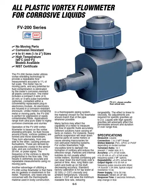
G-5The FV-200 Series meter utilizes vortex-shedding technology to provide a repeatable flowmeasurement accurate to 1% of full scale. The meter has nomoving parts, and any potential for fluid contamination is eliminated by the meter’s corrosion-resistant all plastic construction. The meter includes a compact 2-wire (4 to 20 mA) or 3-wire pulse transmitter (optional), contained within a conveniently replaceable plug-in electronics module. All electronics are housed in a corrosion-resistant enclosure. Unlike meters containing metal or moving parts, the FV-200 is perfect for aggressive or easily contaminated fluids. Applications range from ultra-pure water to highly corrosive chemicals and slurriesOperation of the FV-200 vortex flowmeter is based on the vortex shedding principle. As fluid moves around a body, vortices (eddies) are formed and move downstream. They form alternately, from one side to the other, causing pressure fluctuations. These are sensed by a piezoelectric crystal in the sensor tube, and are converted to a 4 to 20 mA, or pulse signal. The frequency of the vortices is directly proportional to the flow rate. This results in extremely accurate and repeatable measurements using no moving parts.Another advantage of utilizing aFV-200 vortex flowmeter is that there are no gaskets or elastomers in themeter. Therefore, one need only be concerned with the thermoplasticmaterial used in body construction.In a thermoplastic piping system, the material chosen for the flowmeter should match that of the pipe wherever possible.Many factors may affect the capability of a meter to measurethe flow of specific fluids accurately. Different solutions have varying ef-fects on meters. For instance, heavy particle suspension will wear down internal parts on some meters or cause sensing inaccuracies for non-obtrusive metering systems. For vortex flowmeters, high viscosities tend to dampen the formation of vortices and reduce the effective range. Particles and internal bubbles do not usually affect vortex meters. Slurries containing grit can wear down the bluff body over a period of time. Also, long fibers can catch and build up on the bluff,decreasing accuracy. Standard factory calibration is for tap water at32 SSU (1 CST) viscosity and ambient temperature. Viscosityabove 1 CST will raise the minimum readable flow rate, reducing SpecificationSMeasured: Liquidsconnection: 1⁄4 to 2 NPT threadWetted Material: PVC, CPVC or PVDF depending on model number turndown Ratio: 12.1 (except 1⁄4" meter size; 8.1)accuracy: ±1% of full scale, 4 to 20 mA or ±2% of full scale, frequency pulse (“-p” option)Repeatability: ±0.25% actual flow output Signal: 4 to 20 mA orfrequency pulse (source-sink driver; 1A source/ 1.5A sink; typical output resistance 10 Ω)power Supply: 13 to 30 Vdc enclosure: NEMA 4X (IP 66)Response time: 2 seconds minimum, step change in flowrangeability. The effect is linear toviscosity. No adjustments are required for specific gravities up to 2.0. Liquids with high specific gravities will adversely affect the permissible amount and duration of over range flow.Uno Moving parts U corrosion Resistant U 6 to 51 mm (1⁄4 to 2") Sizes UH igh temperature [95°c (203°f)] Models available U niSt certificatefV-211, shown smaller than actual size.ALL PLASTIC VorTex FLowMeTer For CorroSIVe LIquIdSfV-200 SeriesG-6GP O R D E R U S S E R P )r a b i l l i M (For units with a pulse output add a “-P” to the model number, no additional charge.*For high temperature CPVC or PVDF add suffix “-HT” to model number, for additional cost.Ordering Examples: FV-213, 3⁄4 NPT, PVC vortex flowmeter and DPi32, 1⁄32 DIN digital display. FV-226-P, 2 NPT, CPVC vortex with pulse output.FV-231-P-HT, 1⁄4 NPT, PVC vortex with pulse output and high temperature option.。
Variable area flowmeters Vortex flowmeters Flow controllersElectromagnetic flowmeters Ultrasonic flowmeters Mass flowmetersLevel measuring instruments Communications engineering Engineering systems & solutionsGR/PRINTO©KROHNE 04/2001 C 31 0000 01 EElectromagneticFlowmetersG Installation notes G Sizing guide G Ordering guideInstallation notes 3.1Electrical conductivity of the fluidMeasurement is independent of the conductivity of the fluid,provided itis above the limit specified for the various systems.For most primary heads,the lower limit is 5 µS/cm.Distance between primary headand signal converterThe maximum distance is limited byG conductivity of the fluidG for systems with pulsed d.c.field excitation,by the cross-sectional area of the field power cableG for systems with hazardous location approval (European Standardor Factory Mutual),by the capacitance of the signaltransmission cableIf more than one of these points apply,the shortest distance is binding.Precise information on the distance between primary head andsignal converter,connection diagrams and length of the signaltransmission cable is given in the individual signal converterspecifications.Magnetic inductive flowmeters should be installed and wired inaccordance with the information and directions given in theinstallation and operating instructions.Installation in the pipelineG Location and position as required,but electrode axis must beapproximately horizontalG Stud bolts and nuts,to install,make sure there is sufficient roomnext to the pipe flangesG Vibration,support the pipeline on both sides of the flowmeterG Large meter sizes (> DN 200 or > 8”),use adapter pipes to permit axial shifting of counterflangesto facilitate installation.G Straight inlet run minimum of 5 x DN and outlet run minimumof 2 x DN (DN = meter size),measured from electrode axis(undisturbed flow)G Vortex or corkscrew flow,increase inlet and outlet sections orinstall flow straightenersG Strong electromagnetic fields,avoid in vicinity of flowmeterG Thermally insulated pipeline,do not insulate flowmeterG Suggestions for installationTo avoid measuring errors due to air inclusion,please observe the following:Highest point of pipe run(Air bubbles collect inmeasuring tube-faultymeasurements)PreferredlocationsDownpipe“Zero”flowvelocity.Linedrained.Faultymeasurements.open dischargeHorizontal pipe runInstall in slightly ascendingpipe sectionOpen feed or dischargeInstall meter in low section of pipe.Downpipe over 5 m (16 ft) lengthInstall air valve ⊗down-stream of flowmeter (vacuum!).>5mLong pipelineAlways install control and shutoff valvesdownstream of flowmeter (vacuum!).PumpsNever install flowmeter on pump suction side(vacuum!).Background Water Wastewater Abrasive,corrosive and hot products Non-contact measurement κ≥0.05µS/cm Food,Beverage,Pharmaceutical High Pressure and special connectionsCompact and RemoteRemote Calibration /Measuring PrincipleSizing /installation guidesOrdering guide Signal converter 3Sizing Guide 3.1Sizing guide 3.1Flow tablesv = 1m/s Meter size Flow rate Meter size Flow rate DN mm m3/h DN mm m3/h 2.50.017671250176.7140.0452********.4760.10179350346.36100.28274400452.39150.63617500706.8620 1.131********.925 1.76717001385.432 2.89538001809.640 4.52399002209.2507.068610002827.46511.94612004071.58018.09614005541.810028.27416007238.212544.17918009160.915063.617200011310200113.10v = 1ft/s Meter size Flow rateMeter size Flow rate inchUS GMP inch US GMP 1/100.02448010244.801/80.03825012352.511/40.1530014479.813/80.3442516626.691/20.6120020979.213/41.3770241410.112.4480281919.211/43.8250322506.811/2 5.5080363172.629.7921403916.821/215.300485640.2322.032567677.0439.1686410027561.2007212691688.12880156678156.67Recommendations for installationSelection of meter sizeThe size of primary head should if possible be selected to provide a velocity of 2 to 3m/s or 6 to 9ft/sec.for the full-scale range.Minimum full-scale range is 0.5m/s or 1.5ft/sec.,maximum is 10 or 11m/s or 30 or 33ft/sec.,depending on flowmeter type.For fluids with a solids content,the velocity should be between 3 and 5m/s or 9 and 15ft/s to prevent deposits and minimize abrasion.Exact determination of flow velocityFor range setting purposes,the exact flow velocity can be determined using the flow table for each nominal pipe width.Example: v in m/s Nominal pipe diameter DN150Desired measuring range200m 3/hFrom the table we obtain for the flow velocity of 1m/sa flow rate of 63.617m 3/h at DN150; for 200m 3/h the flow velocity v is:Example: v in ft/s Nominal pipe diameter 6”Desired measuring range1000 US GPMFrom the table we obtain for the flow velocity of 1ft/s a flow rate of 88.128 US GPM at 6”meter size; for 1000 US GPM the flow velocity v is:v =200m 3/h x1m/s63.617m 3/hv = 3.144m/s v =1000 US GPM x 1ft /s 88.128 US GPM v = 11.35ft /sProtection classesto IEC 529/EN 60529 Sizing Guide 3.1The reducing angle (α) should not exceed 8°(equivalent to α/2 = 4°),otherwise measuring accuracy may be affected.If the reducing angle is greater,a straight inlet section must be fitted between reducing socket and primary head.For the expanding section,the optimum angle of expansion is α= 8°.ζat α= 8h d 1/d 2 1.2 1.3 1.41.51.6 1.71.81.92.0ζ10.0180.0230.02550.0280.030.03080.03150.03230.0332Expanding sectionPressure Loss CalculationSizing Guide 3.1Ordering GuideOrdering GuideOrdering Guide Ordering Guide 3.1Ordering GuideOrdering GuideOrdering GuideOrdering GuideOrdering GuideOrdering GuideOrdering GuideOrdering GuideOrdering GuideOrdering GuideOrdering GuideOrdering GuideOrdering GuideOrdering GuideOrdering GuideOrdering GuideOrdering GuideOrdering GuideOrdering GuideOrdering Guide 3.1Ordering GuideOrdering Guide。
KROHNE涡街流量计技术资料DWM 2000 DDWM 2000 Electromagnetic Flowmeter with LCD IndicatorOperating instructionsContents1 Display data in operating mode (3)2 Functions of the LCD indicator for the DWM 2000 D (4)2.1 Programmable parameters (4)2.1.1 Flow calibration (4)2.1.2 Current output adjustment (4)2.1.3 Time constant (4)2.2 Electronics module checks (5)2.3 Programming structure (Software n° 1.02) (5)2.3.1 User interface buttons (5)2.3.2 Menu naviagation (6)2.3.3 Summary of programming menus (8)2.4 Parameters stored in the EEPROM (menu 2.4.3) (10)2.5 Error message list (11)2 Operating Instructions DWM 2000 D1 Display data in operating modeOperating Instructions DWM 2000 D 32 Functions of the LCD indicator for the DWM 2000 Dparameters2.1 Programmable2.1.1 Flow calibrationThe G K can be modified in menu 2.1.3 in order to obtain the maximum accuracy at operating conditions. A field calibration requires an accurate reference of velocity. The meter recalibration (G K modification) is also recommended after an exchange of electronics module.The value of the new calibration constant (G K new) can be calculated as follows:GK new = GK old x VaVmwith:Va = actual velocityVm = measured velocity (reference value)2.1.2 Current output adjustmentThe minimum value (i0%) and the maximum value (i100%) of the current output at normal operating conditions can be adjusted from menus 2.2.2. and 2.2.3.The actual values of the i0% and the i100% must be measured with an accurate milliammeter in a 4...20 mA loop.i0% must be in the range 3....12 mA. The factory setting is 4 mA.i100% must be in the range 12....21 mA. The factory setting is 20 mA.2.1.3 Time constantThe time constant value can be set in menu 2.2.4. This value represents the time needed to detect 63% of a simulated flow rate instantaneously raised from 0 to 100%. Time constant range : 5, 10, 15, 20, 25, 30, 50 m.4 Operating Instructions DWM 2000 D2.2 Electronics module checksVarious parameters from the electronics module can be viewed directly for troubleshooting purposes.The DWM 2000 switches to alarm mode when the current output is permanently below 3 mA. In this case the current output value indicates the type of error that occurs:Obey the instructions that follow to find faults and the corrective actions to be undertaken.Call up the error messages (menu 1.2.2.) and note the last one.Refer to the error message list. Replace the electronics module in case of fatal error, deactivate the alarm mode in menu 1.2.1. or the alarm count in menu 1.2.4 (in case of minor error).CMInAinOperating Instructions DWM 2000 D 52.3.2 Menu navigationGo through the steps given in the illustrations that follow to get to the required menu.6 Operating Instructions DWM 2000 DOperating Instructions DWM 2000 D 72.3.3 Summary of programming menusFct. n° Text Description and settings1.0.0. TEST Main menu 1.0.0.1.1.0. CHECK ALL Sub menu 1.1.0. for check of electronic components 1.1.1. MAG. FEQ. Frequency of magnetic field10 Hz ≤ frequency ≤ 14.5 Hz, operating mode1.1.2. FULL SCALE Programmed full scale1 m/s ≤ full scale ≤ 8 m/s1.1.3. U REF Internal voltage referenceU Ref. = 2.5 V1.1.4. AMPLI Test value of amplifier control loopValue ≥ 40 in test modeResultof data check in EEPROM1.1.5. EEPCHECKS“XXX”: measured value = test has been successful“XXX + ALARM”: test has failed and alarm mode has beenactivated (current output value < 4 mA).Resultof data check in EEPROMCHECKS1.1.6. EPValue = 223091.1.7. ZERO KEY Result of zero calibration push button test“OK”: test has been successful; “ALARM”: The test has failedand alarm mode has been activated (current output < 4 mA).This is only a test and does not reset the instrument to zero.Refer to the installation manual to use the Zero Cal button onthe DWM 2000 electronics block correctly.1.2.0. DIAGNOSTIC Sub menu 1.2.0. Diagnostic1.2.1 ALARM MODE Deactivation of the alarm mode (current output < 4 mA) caused by test failure (see menu 1.1.2. to 1.1.7).“YES”: alarm mode is enabled“NO”: alarm mode is disabled1.2.2. REG FAIL. All the error messages that have occurred since the first power-up are listed. Maximum storage capacity: 32 messagesSee section “2.5 Error Message List” for the meaning of errormessages.1.2.3. TESTActivation of PRODUCT (factory auto-diagnostic test mode) or MODECUSTOM (field auto-diagnosis test mode = less severe).Default setting: CUSTOM (field test mode)Resetof the alarms counterCOUNT1.2.4. ALARMUP2.0.0. SETMain menu 2.0.0.PARAMETER2.1.0. DATA BASE Sub menu 2.1.0. Base data2.1.1. FULL SCALE Not available.head calibration constant 0.8 ≤ G K≤ 1.300Primary2.1.3. GKVALUESee section “1.1.1. Flow calibration” on how to recalculate G K.2.1.4. CORRECTION Activation of the low flow linearization for velocity below 3 m/s.Select “YES” or “NO”, default setting:“YES”8 Operating Instructions DWM 2000 DOperating Instructions DWM 2000 D 9Fct. n° TextDescription and settings 2.2.0. CURRENT OUT Sub menu 2.2.0. Current output 2.2.1. CURRENT? Not available 2.2.2. I 0% Calibration of the current output for i 0%Measure the exact value on a milliammeter and press the “+” or “-” key in order to obtain the wished value for i 0% 3 mA ≤ i 0% ≤ 12 mA2.2.3. I 100% Calibration of the current output for i 100%Measure the exact value on a milliammeter and press the “+” or “-” key in order to obtain the wished value for i 100% 12 mA ≤i 100% ≤ 21 mA2.2.4. TIME CONST. Time constant for output of the measured valuesRange: 5, 10, 15, 20, 25, 30, 50 m2.4.0. SPECIAL Sub menu 2.4.0. Special functions 2.4.1. LANGUAGE Language for display text“GB”: English “F”: French “D”: German2.4.2. PASSWORD Not available 2.4.3. EEP PARAM. Display of the different parameters memorised in theEEPROM: see section “2.4 Parameters Stored in the EEPROM”. Read only.2.4.4. FILTER Activation of an electronic filter for noisy applications(foam, solid contents).Select “YES” or “NO”, default setting “YES”.2.4.5. DISPLAY Display of the actual velocity in m/s. The velocity is displayedafter quitting the programming menu.Select “YES” or “NO”. Default setting “NO”.It must be programmed to “NO” before you disconnect the DWM 2000 D.2.4.6. DIAMETER Diameter of the pipe into which the sensor is inserted. Thisvalue is needed for calculating the flow rate. If you enter a value of “0”, this switches off flow rate on the indicator display. Refer also to the CAUTION that follows. 50 mm ≤ diameter ≤ XXXX mmC D th dIf2.4 Parameters stored in the EEPROM (menu 2.4.3)Parameter Comment Typicalvalue CHECKS 1 Check EEPROM n°1 -CHECKS 2 Check EEPROM n°2 -CHECKS BYTE 1 Check EEPROM -CHECKS BYTE 2 Check EEPROM -CPT ALARM. Counting of all the error messagessince the first power-up.-CPT ALARM.2: Counting of all the error messagessince the last reset.-TEST Indication of auto diagnostic testlevelCUSTOMCORRECTION YES/NO Indication of activation of low velocity linearization. YESEP CHECKS Result of the data check in EPROM(see menu 1.1.6.) Value = 22309 With soft V1.02FS Display of the programmed full scalevalues (see menu 1.1.2.)1 m/s ... 8 m/sGK Primary head calibration constant(see menu 2.1.3.)0.8 ... 1.3U REF Internal voltage reference(see menu 1.1.3.)2.4. ... 2.6.T CST Time constant (see menu 2.2.4.) 5 sTEST AMP Test value of the amplifier controlloop (see menu 1.1.4.)75 (95)FM Frequency of the magnetic field(see menu 1.1.1.)10 ... 14.5 HzDIAMETER Diameter of pipeline(see menu 2.4.6)≥ 50 mm10 Operating Instructions DWM 2000 D2.5 Error message listListed below are the messages which can appear in menu 1.2.2. This function stores all the faults that have occurred since the first connection to power.ErrormessagesComment ActionsMAG. FREQ No magnetic field frequency out of range10 Hz ≤ frequency ≤ 14.5 HzReplace the electronics module AMPLI Dysfunction of the amplifier loop Replace the electronics moduleF.S. Programmed full scale out of range(>8 m/s or <1 m/s).Replace the electronics module ZERO KEY Dysfunction of ZERO key (short circuit) Replace the electronics module EP CHECK Data loss in EPROM (software) Replace the electronics module EEP CHECK Data loss in EEPROM (calibration andcalculation data)Replace the electronics module U REF Amplifier voltage reference is damaged Replace the electronics module CURR. OUT Incorrect position of the internal current outputswitchReplace the electronics module FS SWIT EEP Modification of the full scale power on Program the full scale power off ZERO Velocity measurement during the zeroadjustment is more than 0.2 m/s. Deactivate the alarm mode and adjust the zero againOperating Instructions DWM 2000 D 11DWM 2000 D nnnnnnnnnnnnnnnnnnnnnnnnnnnnnnnnnnnnnnnnn nn/doc/12550bd628ea81c758f578d0.htmlAddresses:GermanyNorthern sales officeKROHNE Messtechnik GmbH & Co. KG Bremer Str. 133D-21073 HamburgPhone:+49 (0)40 767 3340 Fax:+49 (0)40 767 33412 nord@/doc/12550bd628ea81c758f578d0.html ZIP code: 10000 - 29999, 49000 - 49999 Western and middle sales office KROHNE Messtechnik GmbH & Co. KG Ludwig-Krohne-Stra?e D-47058 DuisburgPhone:+49 (0)203 301 4416 Fax:+49 (0)203 301 10416 west@krohne.deZIP code: 30000 - 34999, 37000 - 48000, 50000 - 53999, 57000 - 59999, 98000 - 99999Southern sales officeKROHNE Messtechnik GmbH & Co. KG Landsberger Str. 392 D-81241 MunichPhone:+49 (0)89 121 5620 Fax:+49 (0)89 129 6190 sued@/doc/12550bd628ea81c758f578d0.html ZIP code: 0 - 9999, 80000 - 89999, 90000 - 97999Southwestern sales officeKROHNE Messtechnik GmbH & Co. KG Rüdesheimer Str. 40 D-65239 Hochheim/Main Phone: +49(0)6146) 827 30 Fax:+49 (0)6146 827 312 rhein-main@/doc/12550bd628ea81c758f578d0.htmlZIP code: 35000 - 36999, 54000 - 56999, 60000 - 79999Instrumentation and control equipment catalogTABLAR Messtechnik GmbH Ludwig-Krohne-Stra?e 5D-47058 DuisburgPhone:+49 (0)2 03 305 880 Fax:+49 (0)2 03 305 8888kontakt@tablar.de; www.tablar.deKROHNE sales companiesInternationalAustraliaKROHNE Australia Pty LtdQuantum Business Park 10/287Victoria Rd Rydalmere NSW 2116 Phone: +61 2 8846 1700 Fax: +61 2 8846 1755krohne@/doc/12550bd628ea81c758f578d0.html .au AustriaKROHNE Gesellschaft m.b.H.Modecenterstra?e 14A-1030 ViennaPhone:+43 (0)1/203 45 32Fax:+43 (0)1/203 45 32 99info@krohne.atBelgiumKROHNE Belgium N.V.Brusselstraat 320B-1702 Groot Bijgaarden Phone:+32 (0)2 4 66 00 10 Fax:+32 (0)2 4 66 08 00 krohne@krohne.beBrazilKROHNE Conaut Controles Automaticos Ltda.Estrada Das águas Espraiadas, 230 C.P. 56 06835 - 080 EMBU - SP Phone:+55 (0)11-4785-2700 Fax:+55 (0)11 4785-2768 conaut@/doc/12550bd628ea81c758f578d0.html .brChinaKROHNE Measurement Instruments (Shanghai) Co. Ltd., (KMIC)9th Floor, Xujiahui International Building1033 Zhaojiabang Road Shanghai 200030Phone: +86 21 6487 9611Fax:+86 21 6438 7110info@/doc/12550bd628ea81c758f578d0.html Czech RepublicKrohne CZ, spol. s r.o.Sobìsická 15663800 BrnoPhone: +420 (0)545.242 627Fax: +420 (0)545 220 093brno@krohne.czFranceKROHNE S.A.S.Les Ors BP 98F-26103 ROMANS Cedex Phone:+33 (0)4 75 05 44 00Fax:+33 (0)4 75 05 00 48info@krohne.frGreat Britain KROHNE Ltd.Rutherford DrivePark Farm Industrial Estate Wellingborough Northants NN8 6AEPhone:+44 (0)19 33 408 500Fax:+44 (0)19 33 408 501info@/doc/12550bd628ea81c758f578d0.html CISKanex KROHNE Engineering AG Business-Centre Planeta Office 404 ul.Marxistskaja 3109147 Moscow/Russia Phone:+7 (0)095 911 7165Fax:+7 (0)095 742 8873krohne@dol.ruIndiaKrohne Marshall Ltd.A-34/35, M.I.D.C. Industrial Area,H-BlockPimpri Poona 411018Phone:+91 (0)202 744 2020Fax:+91 (0)202 744 2020pcu@/doc/12550bd628ea81c758f578d0.html IranKROHNE Liaison Office North Sohrevardi Ave. 26,Sarmad St., Apt. #9Tehran 15539Phone: +9821 8874 5973Fax: +9821 8850 1268krohne@/doc/12550bd628ea81c758f578d0.html Italy KROHNE Italia Srl. Via V. Monti 75I-20145 MilanPhone:+39 02 4300 661Fax:+39 02 4300 6666info@krohne.itKoreaKROHNE KoreaRoom 508 Miwon Bldg 43Yoido-Dong Youngdeungpo-Ku Seoul, KoreaPhone: 00-82-2-782-1900Fax: 00-82-2-780-1749mail@krohne.co.krNetherlandsKROHNE Nederland B.V.Kerkeplaat 14NL-3313 LC Dordrecht Phone:+31 (0)78 630 6200Fax:+31 (0)78 630 6405Service Direct: +31 (0)78 630 6222info@krohne.nlNorwayKROHNE Norway A.S. Ekholtveien 114NO-1521 MossPhone:+47 (0)69 264 860Fax:+47 (0)69 267 333postmaster@krohne.no PolandKROHNE Polska Sp.z.o.o.ul. Stary Rynek Oliwski 8a 80-324 GdanskPhone: +48 (0)58 520 9211Fax.:+48 (0)58 520 9212info@krohne.plSwitzerland KROHNE AG Uferstr. 90CH-4019 BaselPhone:+41 (0)61 638 30 30Fax:+41 (0)61 638 30 40info@krohne.chSingaporeTokyo Keiso - KROHNE (Singapore) Pte. Ltd.14, International Business Park, Jurong EastChiyoda Building, #01-01/02Singapore 609922Phone: (65) 6567 4548Fax : (65) 6567 9874tks@/doc/12550bd628ea81c758f578d0.html .sg Republic of South Africa KROHNE Pty. Ltd.Bushbock CloseCorporate Park South Midrand, Gauteng P.O. Box 2069Midrand, 1685Tel.: +27 (0)11 314 1391Fax: +27 (0)11 314 1681midrand@krohne.co.zaSpainI.I. KROHNE IBERIA, S.r.l.Poligono Industrial Nilo Calle Brasil, n o. 528806 Alcalá de Henares Madrid Phone: +34 (0)91 883 2152Fax: +34 (0)91 883 4854 krohne@krohne.esUSAKROHNE, Inc.7 Dearborn Road Peabody, MA 01960Phone: +1 (800) FLOWINGPhone: +1 (978) 535 6060 (in MA)info@/doc/12550bd628ea81c758f578d0.htmlRepresentativesAlgeria Argentina Cameroon Canada Chile Columbia Croatia Denmark Ecuador Egypt Finland Gabon Ghana Greece Hong Kong Hungary Indonesia Iran Ireland IsraelIvory Coast Japan Jordan Kuwait Libya Lithuania Malaysia Mauritius Mexico Morocco New Zealand Peru Portugal Romania Saudi Arabia Senegal Slovakia Slovenia Sweden Taiwan Thailand Tunisia Turkey Venezuela YugoslaviaOther countriesKROHNE Messtechnik GmbH & Co. KG Ludwig-Krohne-Str. 5D-47058 DuisburgPhone:+49 (0)203 301 0Fax:+49 (0)203 301 389 export@krohne.deElectromagnetic flowmeters Level measuring instruments Variable area flowmeters Temperature measuring instruments ?Mass flowmeters ?Pressure measuring instruments ?Ultrasonic flowmeters ?AnalysisVortex flowmetersOil and gas industryFlow controllersKROHNE measuring technology - Product overviewK R O H N E 04/2008S u b j e c t t o c h a n g e w i t h o u t n o t i c e。
科隆金属管浮子流量计H250产品特点坚固、简洁、可靠设计来电—洽~询:15 8 050 61 213,找李工模块化、智能化指示器设计与国际市场同步,选用新型ESK2A变送器一次成型测量锥管陶瓷气阻尼装置X-射线探伤低压力损失设计短行程、小型结构、250mm高德国KROHNE公司计算软件保证计算准确介质粘度,密度,温度,压力多级修正全进口流量校验装置保证产品精度100%压力测试,100%产品校验多种指示器M7、M9、M10选择多种信号输出:4-20mA;0.02-0.1MPa;开关信号多种技术认证保证质量可选附件(配件)测量直管段,H系列浮子流量计建议用户安装前五倍口径,后三倍口径的直管段以保证仪表测量精度。
管道法兰、紧固件、密封垫与产品法兰标准相同的管道法兰能够保证仪表正常安装运行。
磁过滤器,当介质中含有铁磁性杂质或初次安装使用流量计时,推荐选用磁过滤器。
F型用于法兰连接,FS型压紧式连接。
HART协议调制解调器,通过与台式计算机或笔记本电脑连接在H250系列(带有HART功能),实现HART功能。
KROV ACAL计算软件:安装在WIN2000或更高系统上实现HART与计算机选型、线性修正、流量累计等功能。
信号转换功能板,实现4-20mA直接在H250上转换转换为0-20mA信号。
认证证书:包括X-射线探伤;材质证明;压力测试证明等。
H250带M40指示器1921年,KROHNE即开始设计生产变面积流量计,H250 M40是勇于创新和成熟技术的完美组合。
基于独特的模块化设计,H250 M40具有广泛的应用。
它可以无需辅助电源纯粹作为一个就地显示机械式仪表也可集成于现场总线系统。
它可以是本安防爆或者隔爆;水平安装、垂直安装或者测量从上到下流向的介质流量。
因此,H250 M40能以可靠的测量满足您几乎所有的需求,并且以优异的性价比给您留下深刻的印象!满足所有防爆要求的仪表所有电子元件被设计为本质安全和无火花,可在爆炸性气体和粉尘环境场合使用。
科隆流量计说明书科隆流量计说明书篇一:科隆质量流量计仪表作业指导书科隆质量流量计仪表作业指导书一、目的:关怀和指导班组有效处理科隆质量流量计故障,对存在的危险进行分析,并采取相应的安全措施进行规避,以确保作业安全和质量。
二、适用范围:各装置中的科隆质量流量计三、接受标准:仪表维护修理规程四、工作原理:科隆质量流量计。
质量流量计以科氏力为基础,在传感器内部有两根平行的流量管,中部装有驱动线圈,两端装有检测线圈,变送器提供的激励电压加到驱动线圈上时,振动管作往复周期振动,工业过程的流体介质流经传感器的振动管,就会在振管上产生科氏力效应,使两根振管扭转振动,安装在振管两端的检测线圈将产生相位不同的两组信号,这两个信号的相位差与流经传感器的流体质量流量成比例关系。
计算机解算出流经振管的质量流量。
不同的介质流经传感器时,振管的主振频率不同,据此解算出介质密度。
安装在传感器器振管上的铂电阻可间接测量介质的温度。
五、常见故障现象分析、推断、处理:硬件故障若出现误差偏大,积算器显示不亮或不增值,显示器空白位等现象,其缘由:.安装不规范,可直接导致流量计零漂,如质量流量计安装在泵出口处较近,传感器支撑强度不够,连接法兰焊接不当产生应力信号,电缆受电磁干扰。
b.接线问题若出现显示器不亮现象,应检查积算器电源连线,若出现保险丝被烧,应确认输入电压与标准电压标称值,交直流形式是否一致。
又若出现积算器不随流量增加时,应检查积算器接线,若积算器装有正/反向程序,应检查流量计接线,因流量计接线不正确,会使积算器在反向流时不递增。
c.工艺介质改变若测量介质出现夹气,气化或两相流等现象,变送器会出现报警显示,严峻时,传感器停止工作。
d.变送器失效。
e.传感器失效。
f.管道吹扫问题。
软件问题质量流量计故障处理——对于刚校验完的流量计安装使用前肯定要留意在当前工况下的零点校验,必需保证流量计中充满介质后关闭两端截止阀才能零点标定,具体的方法有许多种,面板操作、手操器以及使用prolinkⅡ软件。
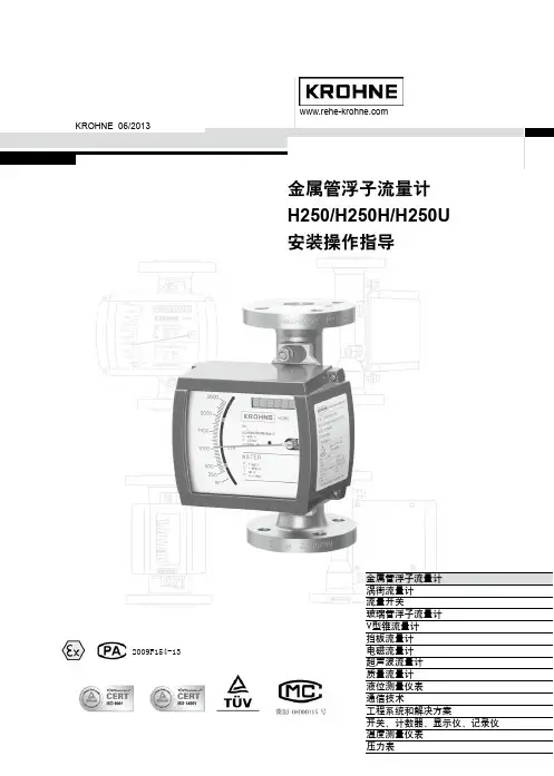
H250金属管浮子流量计说明书(全集)一.简述:H250型流量计产品适用于测量液体、气体的全金属结构金属管浮子流量计。
相对于应测量介质的某一流量,磁性浮子在测量管中对应一全浮子位置,这个浮子位置通过指示器中的磁钢耦合给指针,由刻度盘和指针读出相应的流量值。
浮子流量计适用于垂直管道,介质低进上出的工艺流程。
坚固结构设计的H250型金属管浮子流量计可广泛应用于复杂、恶劣环境条件及各种介质条件的流量测量过程中。
H250特点测量部分坚固的全金属结构设计型浮子流量计。
采用独立,modular概念设计的测量管及指示器,更便于库存,维修的配件的更换。
可选择不锈钢哈氏合金、钛材、PTFE材质测量系统。
新型磁铁耦合结构设计,确保数据传输信号更加稳定。
保温或伴热夹套。
新型设计比H27、H29运行更加安全稳定可靠。
更适合于恶习劣环境和腐蚀严重的介质。
具有良好的搞热性和抗振性。
H250流量计选配M7或M9指示器:M9指示器功能和特点:在指示器中采用一块耦合磁钢完成流量指示、电信号转换和为控制流量波动而设计的阻尼功能,使仪表动行更加安全稳定、可靠。
采用模块式组合设计,可在现场快速的给仪表增加电信号输出、上下限开关、流量累积功能,各功能单元板为插装结构,具有更换部件简单、方便、定位准确的特点。
解决了老型产品由于各环节的人为因素而产生的故障以及至使仪表更换部件后精度降低的缺陷,使仪表的可靠性能得到很大的提高。
采用最新型的ESK Ⅱ信号转换器兼有HART协议能讯功能。
可用PC机或HART协议手持通讯器现场进行术参数的重新设定。
可在就地流量指示型仪表内选择安装:-带4~20mA线性输出和HART协议并无磁滞后的ESK Ⅱ信号转换器(本安型)。
-带有6位LED显示的流量累计单元板-带有上限、下限报警开关的单元板(本安装)。
M7指示器功能和特点:就地指示器线性流量刻度指示。
可选择安装:4~20mA 线性输出ESK变送器(本安或隔爆型)。