横河RAMC金属浮子流量计中文说明书
- 格式:pdf
- 大小:1.38 MB
- 文档页数:76
1前言非常感谢您选择丹东通博电器(集团)有限公司的产品。
MTF 型智能金属管浮子流量计已获1项外观专利,专利号:ZL02 3 53133.9.MTF 型智能金属管浮子流量计已通过国家防爆认证,认证标志:Exia ⅡCT4,Exd ⅡCT4。
使用前请仔细阅读使用说明书,特别是与防爆相关的环境温度等各项要求。
2概述a) 本产品执行标准代号:Q/AMM 014-2010;b) 产品特点:MTF 型智能金属浮子流量计是我公司研制开发的智能系列仪表,是模拟、数字与微处理器相结合的产品。
该流量计将流体流量信号变换为对应模拟电压信号并转换成4~20mA 两线制电流输出并且加载HART 协议通讯,具有高精度,低漂移,抗干扰能力强等特点。
并可以实现对仪表的远程组态、监测、维护、及校准等功能。
可构成生产过程测量、监督管理系统。
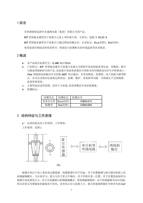
c) 主要用途及适用范围:适用于小流量,低雷诺数的介质流量测量; d) 防爆标志:3 结构特征与工作原理a ) 总体结构及其工作原理、工作特性:工作原理:见图1图1被测介质自下而上垂直流过测量器,将测量器中浮子浮起,浮子内置磁钢与指示器内转轴上的检测磁钢耦合。
当介质浮力,阻力与浮子重力平衡时,浮子停留在某一位置,浮子位置的高低即为被测介质流量的大小。
浮子内的磁钢与检测磁钢耦合,使检测磁钢旋转。
由于检测磁钢为径向充磁,所以在霍尔传感器处的磁场发生变化,此变化正比与流量大小,霍尔传感器把磁信号转变为直流mV防爆形式 防爆标志 防爆证号 本质安全型 Exia ⅡCT4 GYB091670 隔爆型 Exd ⅡCT4 GYB091669 器单片机等 外围电路 两线制 输出 尔传感霍信号,经单片机处理,输出两线制(4-20)mA电流信号并加载符合HART协议通讯的数字信号。
总体结构:流量计主要由测量器和指示器两大部分组成,按连接方式的不同可分为垂直安装和水平安装两种,如图2、图3所示图2垂直式式安装图3水平式安装b) 主要部件或功能单元的结构、作用及其工作原理:测量器部分基本型:全部零件均由304制造,适用于液体测量。
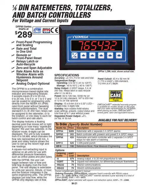
M-211⁄8DIN RATEMETERS, TOTALIZERS, AND BATCH CONTROLLERSFor Voltage and Current InputsThe DPF60 is a combinationmicroprocessor-based digital rateindicator and integrating totalizer.It accepts inputs of 4 to 20 mA,0 to 20 mA, 0 to 5 V, or 1 to 5 V and can be scaled for engineering unitsdirectly from the NEMA 4X (IP66)rated front panel without tweakinginternal potentiometers. The dualstandard 5 A (@ 250 Vac) relays can be assigned to the ratemeter, or tothe totalizer, or one relay to each for batch control and rate alarm.The display features a floatingdecimal point that moves left or right depending on how many “significant figures” the user has selected. In the totalizer mode, 6-digits can bedisplayed. The unit is fully scalable from 0 to 59,999, which indicates the flow rate represented at 20 mA. A peak and valley feature allows the user to call up the recent high and low readings.A square-root extracting input is optional on all units for use with differential pressure flowmeters,such as orifice plates and pitot tubes.With the DPF66, the user can toggle between rate of flow and total flow (6-digits) from the front panel. The rate display is selectable for units per second, minute, or hour,and the totalizer integrates in the same engineering units. The DPF65displays just total flow, while the DPF64 only displays rate of flow.SPECIFICATIONS Accuracy:±0.15% FS for rate and total Temperature Range:Operating:5 to 54°C (41 to 129°F)Storage:-40 to 93°C (-40 to 199°F)Relay Output:2 SPDT relays, 5 A @250 Vac; relays latch or auto-recycle after 0.1 to 99.9 s Power:94 to 126 Vac, 50/60 Hz (or 12 to 24 Vdc) standard; 187 to 253 Vacor 12 to 24 Vdc optional Display: 15 x 8 mm (0.6 x 0.32") LED—6-digits total, 5-digits rate Standby:Non-volatile RAM retains scale settings, presets, output status andtotal flow up to 1 year without power Regulated Power Output: ±5%24 Vdc @ 50 mAOrdering Examples:DPF64-RS232,ratemeter/ batch controller with RS232 output,$289 + 79 = $368.OCW-3, OMEGACARE SM extends standard 2-year warranty to a total of 5 years ($105), $368 + 105 = $473.DPF64-SQRT,digital ratemeter with square root extraction option, $289 + 79 = $368.DPF66 1⁄8DIN, $420, shown actual size.ߜFront-Panel Programmingand Scaling ߜRate and Totalin One Unit ߜRemote orFront-Panel Reset ߜRelays Latch orAuto-RecycleߜZero and Span Adjustable ߜRate Alarm Acts asWindow Alarm with Hysteresis Around Setpoint ߜAnalog Output OptionalDPF60 Series Starts at$OMEGACARE SM extended warranty program is available for models shown on this page.Ask your sales representative for full details when placing an order. OMEGACARE SMcovers parts, labor and equivalent loaners.Panel Cutout: 45 H x 92 mm W(1.772 x 3.622"); DIN standard; 112 mm (4.4") depthCANADA www.omega.ca Laval(Quebec) 1-800-TC-OMEGA UNITED KINGDOM www. Manchester, England0800-488-488GERMANY www.omega.deDeckenpfronn, Germany************FRANCE www.omega.frGuyancourt, France088-466-342BENELUX www.omega.nl Amstelveen, NL 0800-099-33-44UNITED STATES 1-800-TC-OMEGA Stamford, CT.CZECH REPUBLIC www.omegaeng.cz Karviná, Czech Republic596-311-899TemperatureCalibrators, Connectors, General Test and MeasurementInstruments, Glass Bulb Thermometers, Handheld Instruments for Temperature Measurement, Ice Point References,Indicating Labels, Crayons, Cements and Lacquers, Infrared Temperature Measurement Instruments, Recorders Relative Humidity Measurement Instruments, RTD Probes, Elements and Assemblies, Temperature & Process Meters, Timers and Counters, Temperature and Process Controllers and Power Switching Devices, Thermistor Elements, Probes andAssemblies,Thermocouples Thermowells and Head and Well Assemblies, Transmitters, WirePressure, Strain and ForceDisplacement Transducers, Dynamic Measurement Force Sensors, Instrumentation for Pressure and Strain Measurements, Load Cells, Pressure Gauges, PressureReference Section, Pressure Switches, Pressure Transducers, Proximity Transducers, Regulators,Strain Gages, Torque Transducers, ValvespH and ConductivityConductivity Instrumentation, Dissolved OxygenInstrumentation, Environmental Instrumentation, pH Electrodes and Instruments, Water and Soil Analysis InstrumentationHeatersBand Heaters, Cartridge Heaters, Circulation Heaters, Comfort Heaters, Controllers, Meters and SwitchingDevices, Flexible Heaters, General Test and Measurement Instruments, Heater Hook-up Wire, Heating Cable Systems, Immersion Heaters, Process Air and Duct, Heaters, Radiant Heaters, Strip Heaters, Tubular HeatersFlow and LevelAir Velocity Indicators, Doppler Flowmeters, LevelMeasurement, Magnetic Flowmeters, Mass Flowmeters,Pitot Tubes, Pumps, Rotameters, Turbine and Paddle Wheel Flowmeters, Ultrasonic Flowmeters, Valves, Variable Area Flowmeters, Vortex Shedding FlowmetersData AcquisitionAuto-Dialers and Alarm Monitoring Systems, Communication Products and Converters, Data Acquisition and Analysis Software, Data LoggersPlug-in Cards, Signal Conditioners, USB, RS232, RS485 and Parallel Port Data Acquisition Systems, Wireless Transmitters and Receivers。
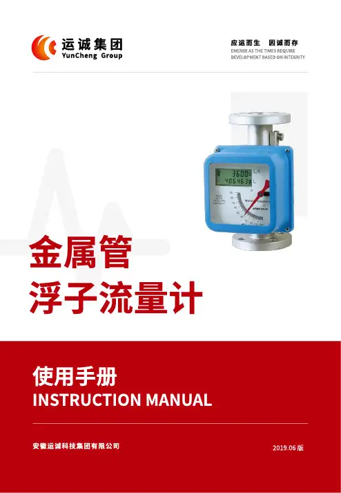
使用手册Instruction manual安徽运诚科技集团有限公司2019.06 版金属管 浮子流量计应运而生因诚而存EMERGE AS THE TIMES REQUIREDEVELOPMENT BASED ON INTEGRITY金属管浮子流量计01概述金属管浮子流量计(金属管转子流量计)是工业自动化过程控制中常用的一种变面积流量测量仪表。
它具有体积小,检测范围大,使用方便等特点,它可用来测量液体、气体以及蒸汽的量,特别适宜低流速小流量的测量。
多年来,金属管浮子流量计以其优良性能和可靠性,以及较好的性能价格比,在石化、钢铁、电力、冶金、轻工、食品、制药、水处理等行业得到了广泛的应用。
本手册面向专业技术人员,适用于金属管浮子流量计的设计选型,也可用于最终用户在使用时的参考。
手册分别介绍了本系列金属管浮子流量计的工作原理、功能特点、技术参数、仪表类型及外形、流量计算、接线方法和安装、维护等。
本手册只针对本系列金属管浮子流量计的设计选型和使用,同时厂家保留某些技术参数改进而不预先通知的权利。
02测量原理本系列金属管浮子流量计主要由两大部分组成:传感器和指示器。
传感主要由连接法兰、测量锥管、浮子和上下导向器组成;指示器主要由壳体、磁传动系统、刻度盘和电远传系统组成。
在垂直的锥形测量管内,有一可上下移动的测量部件——浮子(图1),当流体自下而上通过锥形管时,浮子受到流体的作用力,沿锥形管向 上移动。
当流体的流量增大时,浮子的位移量增大;反之,流体的流量减少时,浮子的位移量变小。
也就是说,流体流量的大小,决定了浮子在测量管中的位置,从而决定了浮子和锥形管之间环形面积的大小。
当流体的流量保持在一个恒定的流量Q时,浮子也处于一动平衡状态,停留在锥形管中的一位置h,此时,浮子和锥形管之间的环形面积保持恒定。
浮子受到三个力的作用:浮子的重力G,浮子受到的浮力F,浮子受到流体的作用力P,这三个力达到平衡。
根据流体动力学的柏努力方程、力平衡原理和流体连续性定律,可以计算出此时通过环形面积的瞬时流体流量,所以,金属管浮子流量计是采用可变面积测量流量的原理。
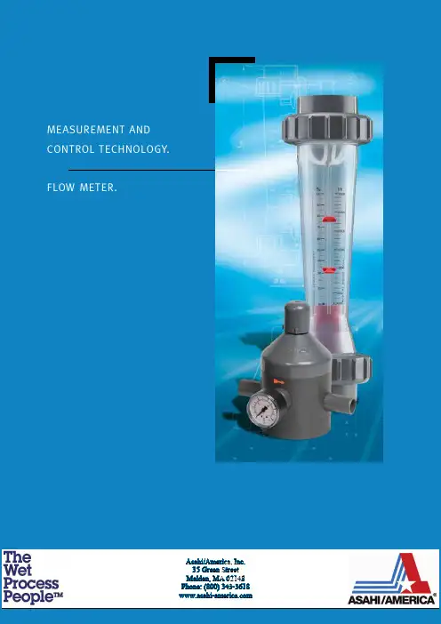
MeasureMent and control technology.Flow Meter.Heat Requirement CalculationsAsahi/America, Inc.35 Green StreetMalden, MA 02148Phone: (800) 343-36184Float-typeflow meterFloat-type flow meterKey to symbols▲ PA (polyamide Trogamid)■ PSU (polysulphone)● PVC◆ PMMA (polymethylmethacrylate “Plexiglas”)Va 1.4571Tg Malleable cast iron5Flow meter M 335 / M 350Flow meter M 335 / M 350Measuring ranges 50 – 60,000 l/hFunction The FRANK flow meter M 335 / M 350 operates on the float principle and is used for flow rate measurements in closed pipelines. The medium flows through the vertically installed flow meter from bottom to top. This raises the float and shows the current flow rate on the scale on the measuring device. The read-off edge corresponds to the largest diameter of the float.FRANK M 335 / M350 flow meters come as standard with a water scale and a % scale, and two setpoint indicators.Special features:• Fracture-proof and corrosion-resistant • Radially removable• Special adhesive scales for liquid and gaseous media• Holder for accessories (limit value contacts)• Measuring tube carries the DN label, and also the measuring range and material • PVDF floats and stops as standard• Measuring ranges 50 – 60,000 l/h6Flow meterM 335 / M 350 Operating pressure: max. PN 10 at 20 °C* o nly with PVDF screw connectionFlow meter M 335 / M350Flow meter M 335 / M 3509Flow meter M 335 / M35010Flow meter M 335 / M 350Special scales as requested by the customer Details required: Medium, spec. weight in g/cm3, viscosity in cP or mPas, operating temperature in °C, desired measuring range in l/h.Application instructions for special scalesWhen applying special scales later, ensure that the marking ▼ on the scale corresponds with the one on the measuring tube.11Flow meter M 335 / M 350Accessories Limit value contact Z 40 min.Limit value contact Z 42 max.For further information, refer to the separate data sheets.Installation and assembly instructions • I nstall the flow meter into the pipeline system vertically and without tension.• P rovide an inlet and outlet section, Inlet approx. 10 x DN, outlet approx. 5 x DN.This table is used to correct values displayed for gases by the flow meter if the operating pressure deviates from the pressure used as a basis for the calibration. The values displayed on the flow meter are simply multiplied by the factor corresponding to the operating pressure.We supply special scales for operating pressures of between 1 and 8 bar (see Page 10).Notes on operation• A void pressure surges, as these can damage the unit.• E xercise caution when installing. The measuring tube must not come into contact with solvent.• B efore start-up, make sure that the connected parts are sufficiently tightened.• T he union nuts must not be mixed up on a measuring tube made from the material PVDF . The overall length also does not correspond to the dimensions table.We reserve the right to make technical changes in the interest of improvement.12Flow meter M 123Flow meter M 123Measuring ranges 15 – 1,000 l/h Function The FRANK M 123 flow meter works on the float principle and is used to measure the flow rate in closed pipelines. The medium flows through the vertically installed flow meter from bottom to top. This raises the float and shows the current flow rate on the scale on the measuring device. The read-off edge corresponds to the largest diameter of the float.FRANK M 123 flow meters have a water scale and 2 setpoint indicators as standard.Special features:• Fracture-proof and corrosion-resistant • Radially removable • A dhesive special scales, for liquid and gaseous media • Holder for accessories (limit value contacts)• Measuring tube carries the DN label, and also the measuring range and material • PVDF floats and stops as standard • Measuring ranges 1.5 – 1,000 l/h • Less space required thanks to short overall length13Flow meter M123Operating pressure: max. PN 10 at 20 °C14Flow meter M 123Screw connection with fusion spigot Screw connection with threaded socket15Flow meter M12316Flow meter M 123Special scales as requested by the customer Details required: Medium, spec. weight in g/cm3, viscosity in cP or mPas, operating temperature in °C, desired measuring range in l/h.Application instructions for special scalesWhen applying special scales later, ensure that the marking ▼ on the scale corresponds with the one on the measuring tube.AccessoriesLimit value contact Z 40Limit value contact Z 42Installation and assembly instructions• I nstall the flow meter into the pipeline system vertically and without tension.• P rovide an inlet and outlet section Inlet approx. 10 x DN, outlet approx. 5 x DN.Notes on operation• A void pressure surges, as these can damage the unit.• E xercise caution when installing. The measuring tube must not come into contact with solvent.• B efore start-up, make sure that the connected parts are sufficiently tightened.• T he union nuts must not be mixed up on a measuring tube made from the material PVDF. The overall length also does not correspond to the dimensions table.We reserve the right to make technical changes in the interest of improvement.17Limit value contact Z 40 min., Z 42 max.18Flow meterM 10 to M 13PMMA flow meter M 10 to M 13Measuring ranges 1.5 – 100 l/h H2OFunctionFRANK M 10 to M 13 flow meters work on the float principle and are used to measure the flow rate in closed pipelines. The medium flows through the vertically installed flow meter from bottom to top. This raises the float and shows the current flow rate on the scale on the measuring device. The read-off edge corresponds to the largest diameter of the float (ball).Operating pressure: max 10 bar at 20 °C Special features:• Compact and robust design• Short overall length• With needle valve (M10 and M 13), very fine adjustment19Flow meter M 10 to M13FRANK plastic AGHerbert-Frank-Straße 26D-72178 Waldachtal Telefon +49 (0) 7486 181 0Fax +49 (0) 7486 181 337 E-Mail info@frankplastic.de www.frankplastic.de。
目录仪表的键盘和前面板-------------------------------------2 仪表功能----------------------------------------------------4 仪表程序----------------------------------------------------4 仪表键盘和中控方式的转换----------------------------6 仪表的启动和停止----------------------------------------7 仪表重量和容积方式的转换----------------------------8 给定量的输入----------------------------------------------8 显示事件信息----------------------------------------------8 服务数据----------------------------------------------------9 标定功能----------------------------------------------------9 调零-----------------------------------------------------14 计数器1或2的复位-------------------------------------13 安装与调整-------------------------------------------------13 维护与保养-------------------------------------------------14 事件信息----------------------------------------------------16(一)仪表的键盘1各按键的作用如下:启动键和停止键。
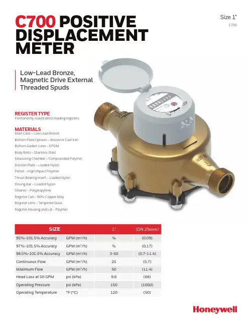
C700Size 1"C700 POSITIVE DISPLACEMENT METERREGISTER TYPE Permanently sealed direct reading registers.MATERIALSMain Case – Low Lead BronzeBottom Plate Options – Bronze or Cast Iron Bottom Gasket-Liner – EPDM Body Bolts – Stainless SteelMeasuring Chamber – Compounded Polymer Division Plate – Loaded Nylon Piston – High Impact Polymer Thrust Bearing Insert – Loaded Nylon Driving Bar – Loaded Nylon Strainer – Polypropylene Register Can – 90% Copper Alloy Register Lens – Tempered GlassRegister Housing and Lid – PolymerLow-Lead Bronze,Magnetic Drive External Threaded Spuds2TYPICAL ACCURACY AND PRESSURE LOSSA C C U R A C Y (%)FLOW RATE (GPM)H E A D L O S S (P S I )1010.10.010.0010.000110.110100OPERATIONThe C700 is an oscillating piston style, positive displacement water meter.A piston is located inside the meter chamber, which rotates with water flow and each piston revolution is equivalent to a known volume of water. The piston movement is transferred by a magnetic drive to a straight reading sealed register which contains the appropriate reduction gearing. COMPLIANCE TO STANDARDS The C700 complies with American Water Works Association Standard C700, latest revision. C700 low-lead bronze models are NSF-61 certified (including Annex G) and complies with California Proposition 65. INSTALLATIONThe meter must be installed in a clean pipeline, free from any foreign materials. Install the meter with direction of flow as indicated by the arrow cast in the meter case. The meter may be installed in horizontal, vertical or inclined lines. Referto instruction sheet. Maintenance and installation Manual 03/2020. APPLICATIONThe meter is for use only with potable cold water up to 120°F (50°C) and working pressures up to 150 psi. The meter will register between 98.5% and 101.5%at normal and high flows and between 97% and 101.5% at the AWWA specified low flow. Accuracy tests are made before shipment, so no adjustments need to be made before installation. CONSTRUCTIONThe meter consists of a straight through-flow main case, dual inlet measuring chamber, vertically grooved oscillating piston, high capacity strainer, removable bottom plate, full rubber liner, body bolts with integral washers and a magnetically driven register. The main case is cast inlow-lead bronze with raised characters designating model, size and direction of flow. Main case bottom plates are available in a choice of bronze or, if frost protection is desired, in cast iron. The 2-piece snap-fit measuring chamber is madeof a top and bottom inlet, side outputdesign and features a unique self-flushingsediment well.Other features include a removable,contoured division plate, captive drive barand high torque magnet complete with anylon bushing. The flow-stream balancedpiston has a unique thrust bearing insertand features a Turbulence Seal™ systemwhich passes debris while sustaining themost linear accuracy curve in the industry.Each register is secured to the maincase with a tamper proof plug to preventunauthorized removal.READING OPTIONSC700 meters are available with AbsoluteEncoder register options to provide waterusage output to the entire spectrum ofmeter reading systems, giving flexibilityto utilities implementing or upgradingreading technologies. Refer to the followingdocuments for more information:Absolute Encoder Register 03/2020DRIVEThe magnetic drive design facilitatescoupling between the measuring chamberand the external register. The coupling isabsolute at all rated flows.CONNECTIONSMeter casing spuds have external straightthreads conforming to ANSI B.1.20.Low-lead bronze coupling nuts andtailpieces are available. Tailpieces haveexternal taper pipe threads conforming toANSI B.1.20.1. Their lengths and threadsizes are as specified by AWWA Standards.MAINTENANCEThe measuring chamber assembly canbe removed for cleaning or replacement.Pretested measuring unit assembliesare available for exchange or purchase,and spare parts are available fromour warehouse or designated regionallocations. Honeywell Smart Energy staffsand operates a repair facility at its U.S.manufacturing plant in Ocala, FL.3Find Out More************************* Honeywell Smart Energy10 SW 49th Avenue, Bldg. 100 Ocala, FL 34474United StatesT +1 800 874 0890F +1 352 368 1950208 S. Rogers LaneRaleigh, NC 27610-2144United StatesT +1 800 786 2215 (Sales information) T +1 866 554 9007 (Product support)1100 Walker’s Line, Suite 101 Burlington, Ontario L7N 2G3 CanadaT +1 866 703 7581F +1 905 634 6705Samara Shops, Torre A piso 1Av Santa Fe 94Col. Zedec Santa FeCP. 01210MexicoT +52 52414873 C700 1” Specification Sheet 08/2020© 2020 Honeywell International Inc.。
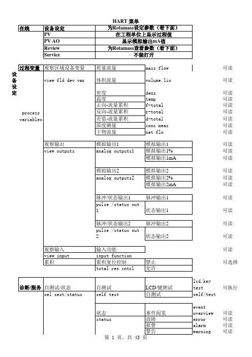
可读设备可读设定可读可读可读可读可读可读可读可读可读可读可读可读可读可读可读可读可读可读可选择可执行可读可读可读可读/写/写/写/写/写/写可读/写可读/写可选择可选择可读/写可读/写可读/写可选择可读/写可读/写可读/写可选择可读/写可读/写可读/写可选择可选择可选择可选择可选择可读/写可选择第 5 页,共 43 页可选择可选择可选择可选择可选择可选择可选择可选择可选择可选择可读/写可选择可选择可读/写可读/写可读/写可读/写可读/写/写/写/写/写/写/写/写/写/写/写/写/写/写/写/写/写/写/写/写/写/写/写/写/写/写/写/写/写可读/写可读/写可读/写可读/写可选择可读/写可选择可选择可选择可读/写/写/写/写/写/写可读/写可读/写可读可读/写可读/写可读/写可读/写可读/写可读可读可读可读可读可读可读查看设备信息prviewdeviceinfotemp fixed value none mass flo vol flo dens temp conc measnet flonone mass flo vol flo dens temp conc measnet flopulse status outno function none mass total forw mass total rewvoltotal forwvoltotal rew mass flowvol flo dens tempconc measnet forw net rev net flow no function bi-directio naltotal switch mass flo alm1 mass flo alm2 mass flo alm1+2 vol flovol flo alm 2 vol flo alm 1+2 densalm1 densalm2 densalm1+2 tempalm1 tempalm2 tempalm1+2 CONCalm1 concalm2 concalm1+2 net alm1 net alm2 netalm1+2 slug alarm empty alarm corrosio n alarmpulse status outno function none mass total forw mass total rewtotal forwvoltotal rew mass flowvol flo dens temp conc measnet forw net rev net flowfunction bi-directio naltotal switch mass flo alm1 mass flo alm2 mass flo alm1+2 vol flo alm 1 vol flo alm 2 vol flo alm 1+2 densalm1 densalm2 densalm1+2 tempalm1 tempalm2 tempalm1+2 CONCalm1 concalm2 concalm1+2 net alm1 net alm2 netalm1+2 slug alarm empty alarm corrosio n alarmonactive off active no funtctio n autozero total test0%signal lockon act off actmeas value hold drive gain damping。

HJM 型横截面流量计安装使用说明书常州肯诺自动化设备有限公司一、概述随着电厂自动化控制水平的进步,燃煤锅炉的负荷、煤粉量及配风量需要实现在线监测和自动协调控制,使锅炉一、二次配风合理,各风管内风速均匀,就可以保证锅炉燃烧稳定,提高锅炉效率,和经对于生产过程的技术分析济核算等是十分必要的。
但是,迄今为止,存在风速的测量与标定都比较困难,测量的准确度比较底(达不到压力和温度的测量水平),流量计的通用性差等问题。
引起这些问题的原因,主要有以下三个原因:1、流体性质的多样性:压力与温度参数的高低;流体中含尘量的多少;流体粘度的差别;单相流体与多相流体的区别,等等。
这些物性会影响流体状态,在流量测量中必须加以考虑,但又很难精确。
2、管路系统的多样性:管道的直与弯的区别;圆截面与非圆截面的区别;直管段长短不一样,等等。
都会影响流动状态,使流量测量复杂化。
3、流动状态的多样性:由于以上流体的物性和采用管道的不同,会影响到流体的流动状态,诸如旋转流和脉动流;层流、紊流;流动是否达到充分发展,等等。
以上三种影响流量测量的因数,要求我们必须针对被测对象的实际情况选择合适的流量计。
众所周知,由于火力发电厂锅炉二次风管道的直管段极短,或者几乎没有;而且二次风的管道在极有限的距离内,分布有T形管道、L形管道、调节风门、变径管等,使管道内二次风的流动状态变化莫测,这就使得二次风的测量成为非常困难的事情。
在许多场合就不测量了。
在必须测量的场合,不得不采用机翼型测量装置,但这只是一个无奈之举。
因为机翼型测量装置的主要缺点,就是要大大减少二次风的流通面积,一般要减少50%-60%左右。
为了在减少一半以上流通面积的情况下,仍然要保持应有的风量,以维持正常的发电复核的要求,就必须提高风机的功率,增大能源消耗;即使如此,因机翼型结构仍比较长,在一些场合,仍然不能使用机翼型测量装置;即使已安装了机翼型测量装置,因为前后直管道不满足,无法保证测量精度。
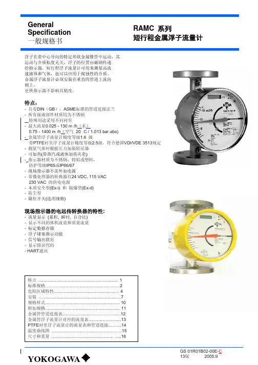
横河转子流量计RAMC01产品名称:RAMC金属转子流量计产品型号:产品规格:产品单位:台产品价格:0[产品详细介绍]:一般规格书浮子在带中心导向的特定形状金属锥管中运动,其运动与介质粘度无关,浮子的位置由磁钢传递给指示器。
短行程浮子流量计可用来测量高流速液体和气体,也可以应用于腐蚀性的介质。
金属浮子流量计必须安装在垂直的管道上流向朝上。
更换指示器不影响其精度。
特点-具有DIN(GB),ASME标准的管道连接法兰-所有接液部件材质均为不锈钢-特殊用途采用不同衬里-最大流量0.025~130m3/h(水) 0.75~1400m3/h(空气20℃/1.013 bar abs)-金属管浮子流量计精度等级1.5级带PTFE衬里浮子流量计精度等级2.5级-测量气体时根据压力加装阻尼器-可加热(带蒸汽或液体加热夹套)-指示器材质为不锈钢,铸铝或塑料,防护等级IP65或IP66/67-现场指示器不需外加电源-带微处理器的转换器有24V DC,115V AC,230V AC的供电电源-本质安全型(Ex-i)和隔爆型(Ex-d)-防尘型-限位开关(选用规格)现场指示器的电远传转换器的特性-流量显示(累积,瞬时,百分比)-显示不同的体积流量和质量流量-标定数据存储-浮子堵塞指示功能-信号输出阻尼-显示错误代码- HART通讯横河金属转子流量计-浮子流量计横河转子流量计一、横河转子流量计流量测量方法和仪表的选用横河浮子流量计,又称横河转子流量计,是变面积式流量计的一种, 在一根由下向上扩大的垂直锥管中, 圆形横截面的浮子的重力是由液体动力承受的, 浮子可以在锥管内自由地上升和下降。
在流速和浮力作用下上下运动,与浮子重量平衡后,通过磁耦合传到与刻度盘指示流量。
一般分为玻璃和金属转子流量计。
横河金属转子流量计是工业上最常用的,对于小管径腐蚀性介质通常用玻璃材质,由于玻璃材质的本身易碎性,关键的控制点也有用全钛材等贵重金属为材质的转子流量计二、横河转子流量计的特点:横河转子流量计是工业上和实验室最常用的一种流量计。

ZRN-LZ型系列金属管浮子流量计安装使用说明书目录一、产品概况 (2)二、原理结构 (2)三、技术要求 (2)四、电性能 (3)五、限位开关报警装置 (3)六、型号规格 (4)七、安装尺寸 (5)八、使用与维修 (6)九、仪表常见故障的维修 (7)十、防爆产品使用注意事项 (8)十一、设计选用及订货须知 (8)ZRN-LZ系列金属管浮子流量计安装使用说明书一、产品概况ZRN-LZ系列金属管浮子流量计结构简单、工作可靠、准确度高、适用范围广。
与玻璃转子流量计相比较能耐较高的压力。
ZRN-LZ系列流量计具有就地指示、电远传、限位开关报警、耐腐蚀、夹套型、阻尼型和防爆等品种。
广泛应用于国防、化工、石油、冶金、电力、环保、医药和轻工等部门的液体、气体流量的测量与自动控制。
流量计检测部分零件均有1Cr18Ni9Ti不锈钢材料制成,特殊场合也可由Cr18Ni12Mo2Ti或F46等耐腐蚀材料组成。
流量计除特殊规格外,高度均为250mm。
连接法兰采用GB/T9119.8~10标准,也可根据用户特殊要求定制。
二、原理结构由下而上的流体通过直立的测量管时,浮子在压差的作用下上升、浮子上升的高度即代表流量的大小。
并通过浮子中的磁钢与指示器中的磁钢耦合联结传递给指示器,带动指示器中的指针转动。
8指示器7弹簧卡圈6浮子止挡5管体4测量体3浮子2浮子导向盘1连接法兰图1仪表结构图三、技术要求1.测量范围:水(2.5~6000)L/h;空气(0.07~2000)m3/h(在0.101025MPa、20℃)。
2.准确度等级:1.5、2.5级。
3.量程比:10:1。
4.工作压力:DN15~50,4MPa ;DN80~100,1.6MPa 。
5.介质温度:-80℃~200℃(内衬F46流量计0℃~80℃)。
6.液体介质粘度:DN15<5mPa·s ;DN25~100<5mPa·s 。
7.连接方式:法兰连接、螺纹连接等;法兰采用GB/T9119.8~10标准。
最新磁性浮子液位计的使用说明和安装保养●工作原理与结构磁性翻柱(磁翻柱)液位计是根据磁极耦合原理、阿基米德(浮力定律)等原理巧妙地结合机械传动的特性而开发研制的一种专门用于液位测量的装置。
在此基础上,不断扩大其使用范围,延伸出多种类型的产品,在检测液位的同时我们赋予它们更多的实用功能。
该类型的仪表都有一个容纳浮球的腔体(称为主体管或外壳),腔体通过法兰或其他接口与容器组成一个连通器。
这样,仪表的腔体内的液面与容器内的液面是相同高度的,所以腔体内的浮球会随着容器内液面的升降而升降;这时候我们并不能看到液位,所以我们在腔体的外面装了一个翻柱显示器,因为我们在制造浮球时在浮球沉入液体与浮出部分的交界处安装了磁钢,它与浮球随液面升降时,它的磁性透过外壳传递给翻柱显示器,推动磁翻柱翻转180°;由于磁翻柱是有红、白两个半圆柱合成的圆柱体,所以翻转180°后朝向翻柱显示器外的会改变颜色(液面以下红色、以上白色),两色交界处即是液面的高度。
为了扩大它的使用范围,还可以根据相关标准及要求增加液位变送装置,以输出多种电信号(如:电阻信号、电压信号、或者电流信号)。
其中,4~20mA电流信号是比较常用的一种。
比如:在监测液位的同时磁控开关信号可用于对液位进行控制或报警;在翻柱液位计的基础上增加了4~20mA 变送传感器,在现场监测液位的同时,将液位的变化通过变送传感器、线缆及仪表传到控制室,实现远程监测和控制。
●产品特点本液位计是在借鉴国内外同类产品的基础上,积极吸收、揉合众多产品的优点,通过公司技术人员的精心设计而成的,采用优质磁体和进口电子元件。
产品具有:测量范围大,读数直观清晰;密封结合面少,不易渗漏,安全可靠;指示部分与被测介质完全隔离;易于安装、维修方便。
●适用范围:随着市场需求的变化公司产品也在不断地实现质量技术的升级和生产工艺的改进、拓宽本液位计的应用领域及适用范围。
另外,本液位计输出信号多样,实现远距离的液位指示、检测、控制和记录。
1前言非常感谢您选择丹东通博电器(集团)有限公司的产品。
MTF 型智能金属管浮子流量计已获1项外观专利,专利号:ZL02 3 53133.9.MTF 型智能金属管浮子流量计已通过国家防爆认证,认证标志:Exia ⅡCT4,Exd ⅡCT4。
使用前请仔细阅读使用说明书,特别是与防爆相关的环境温度等各项要求。
2概述a) 本产品执行标准代号:Q/AMM 014-2010;b) 产品特点:MTF 型智能金属浮子流量计是我公司研制开发的智能系列仪表,是模拟、数字与微处理器相结合的产品。
该流量计将流体流量信号变换为对应模拟电压信号并转换成4~20mA 两线制电流输出并且加载HART 协议通讯,具有高精度,低漂移,抗干扰能力强等特点。
并可以实现对仪表的远程组态、监测、维护、及校准等功能。
可构成生产过程测量、监督管理系统。
c) 主要用途及适用范围:适用于小流量,低雷诺数的介质流量测量; d) 防爆标志:3 结构特征与工作原理a ) 总体结构及其工作原理、工作特性:工作原理:见图1图1被测介质自下而上垂直流过测量器,将测量器中浮子浮起,浮子内置磁钢与指示器内转轴上的检测磁钢耦合。
当介质浮力,阻力与浮子重力平衡时,浮子停留在某一位置,浮子位置的高低即为被测介质流量的大小。
浮子内的磁钢与检测磁钢耦合,使检测磁钢旋转。
由于检测磁钢为径向充磁,所以在霍尔传感器处的磁场发生变化,此变化正比与流量大小,霍尔传感器把磁信号转变为直流mV防爆形式 防爆标志 防爆证号 本质安全型 Exia ⅡCT4 GYB091670 隔爆型 Exd ⅡCT4 GYB091669 器单片机等 外围电路 两线制 输出 尔传感霍信号,经单片机处理,输出两线制(4-20)mA电流信号并加载符合HART协议通讯的数字信号。
总体结构:流量计主要由测量器和指示器两大部分组成,按连接方式的不同可分为垂直安装和水平安装两种,如图2、图3所示图2垂直式式安装图3水平式安装b) 主要部件或功能单元的结构、作用及其工作原理:测量器部分基本型:全部零件均由304制造,适用于液体测量。
横河电机株式会社IM 01E20C02-01C-C 第5版i IM 01E20C02-01C-C第4版: 2005年2月(KP)横河电机株式会社 版权所有2003目录1.简介..............................................................................................................1-11.1安全使用电磁流量计............................................................................1-21.2保修.....................................................................................................1-31.3分离型传感器配套................................................................................1-31.4ATEX 文件............................................................................................1-42.操作须知.......................................................................................................2-12.1检查型号和规格...................................................................................2-12.2附件.....................................................................................................2-12.3存放须知..............................................................................................2-12.4安装地点须知.......................................................................................2-23.安装..............................................................................................................3-13.1安装地点..............................................................................................3-13.2安装.....................................................................................................3-14.接线..............................................................................................................4-14.1接线须知..............................................................................................4-14.2电缆.....................................................................................................4-14.3接线口..................................................................................................4-34.4接线.....................................................................................................4-44.4.1打开壳盖.......................................................................................4-44.4.2端子结构.......................................................................................4-44.4.3电源电缆接线须知.........................................................................4-54.4.4直流电源连接................................................................................4-54.4.5接地..............................................................................................4-64.4.6分离型传感器与AXFA14转换器连接.............................................4-64.4.7连接外部仪表................................................................................4-74.4.8安装壳盖.......................................................................................4-85.基本操作步骤(显示单元的使用)...............................................................5-15.1操作面板的构造和功能........................................................................5-15.2显示单元的设置方法............................................................................5-25.2.1显示模式→设置模式.....................................................................5-25.2.2设置模式.......................................................................................5-45.3参数设置步骤.......................................................................................5-45.3.1选择型数据的设置示例:流量单位................................................5-45.3.2数值型数据的设置示例:流量量程................................................5-65.3.3字符数字组合型数据的设置示例:位号........................................5-7ii IM 01E20C02-01C-C6.参数说明.......................................................................................................6-16.1参数.....................................................................................................6-16.2参数列表..............................................................................................6-16.3参数列表总览.......................................................................................6-26.4参数说明............................................................................................6-12(1) 菜单B :快速设置项...........................................................................6-12(2) 菜单C :基本设置项..........................................................................6-15(3) 菜单D :累计值设置项.......................................................................6-17(4) 菜单E :脉冲设置项...........................................................................6-19(5) 菜单F :状态功能设置项....................................................................6-20(6) 菜单G :报警设置项..........................................................................6-26(7) 菜单H :显示设置项..........................................................................6-30(8) 菜单J :辅助功能设置项....................................................................6-30(9) 菜单K :诊断功能设置项...................................................................6-33(10) 菜单M :自动调零功能设置项..........................................................6-33(11) 菜单N :环路测试设置项..................................................................6-34(12) 菜单P :参数保护项.........................................................................6-346.5报警功能............................................................................................6-356.5.1报警级别.....................................................................................6-356.5.2报警选择.....................................................................................6-366.5.3报警和警告提示..........................................................................6-386.6AXF 一体型流量计须知.......................................................................6-407.使用智能终端(BT200)进行操作............................................................7-17.1BT200基本操作...................................................................................7-17.1.1键盘布置及显示............................................................................7-17.1.2按键说明.......................................................................................7-17.2使用BT200操作AXFA14......................................................................7-37.2.1BT200连线....................................................................................7-37.2.2BT200的数据更新和上传下载功能................................................7-37.2.3BT200界面和流量数据显示...........................................................7-47.3使用BT200进行参数设置.....................................................................7-47.3.1BT200选择型数据的设置:流量单位............................................7-57.3.2BT200数字型数据的设置:流量量程............................................7-67.3.3BT200字符数字组合型数据的设置:位号.....................................7-78.使用HART 手操器进行操作...........................................................................8-18.1通讯线路状况.......................................................................................8-28.1.1AXFA14和HART 手操器之间的连接..............................................8-28.1.2通讯线路要求................................................................................8-28.2HART 手操器(275型)的基本操作.....................................................8-38.2.1键盘布置和功能............................................................................8-38.2.2显示..............................................................................................8-48.2.3调入菜单地址................................................................................8-48.2.4输入、设置和发送数据..................................................................8-58.3参数.....................................................................................................8-58.3.1参数结构.......................................................................................8-58.3.2数据更新.......................................................................................8-58.3.3问题检查.......................................................................................8-68.3.4设置参数.......................................................................................8-68.3.5菜单树.........................................................................................8-21iii IM 01E20C02-01C-C9.实际操作.......................................................................................................9-19.1运行前调零..........................................................................................9-19.1.1利用显示单元开关进行调零..........................................................9-29.1.2通过外部状态输入进行调零操作...................................................9-310.维修............................................................................................................10-110.1零部件更换........................................................................................10-110.1.1更换保险丝..................................................................................10-110.1.2更换显示单元..............................................................................10-210.1.3更换放大器..................................................................................10-310.2开关设置............................................................................................10-410.2.1设置熔断开关..............................................................................10-410.2.2设置写保护开关..........................................................................10-410.3故障检修............................................................................................10-510.3.1无指示.........................................................................................10-510.3.2零点不稳定..................................................................................10-610.3.3显示与实际流量不一致................................................................10-711.概述............................................................................................................11-112.防爆型仪表.................................................................................................12-112.1CENELEC ATEX (KEMA).................................................................12-112.2FM .....................................................................................................12-212.3CSA ...................................................................................................12-312.4TIIS....................................................................................................12-4TIIS 防火设备的安装和操作注意事项...........................................................EX-B03E1.概述 (1)2.防爆结构防火型电气设备 (1)3.术语 (1)4.防火设备的安装 (2)5.防火设备的外部接线 (2)6.防火设备的维修 (3)7.防火型电缆接入设备的选择....................................................................31.简介本仪表在出厂前已经过全面调试。