海信日立空调产品介绍课件
- 格式:pptx
- 大小:31.96 MB
- 文档页数:65


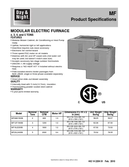
MODULAR ELECTRIC FURNACE2, 3, 4, and 5 TONSFEATURESS Modular Blower Cabinet, Air Conditioning or Heat Pump readyS Upflow, horizontal right or left applicationsS Downflow requires sub−base accessoryS Electronic fan control boardS Three speed PSC motor on all modelsS Matches with AC and HP cased coils (Hot water coil may be used, but doesn’t match case size)S Accepts accessory two stage outdoor thermostatsS208/230−1−60 supply voltageS Requires a “NO HEAT KIT” if installed without electric heat.S Field installed electric heater packages from5kW−25kW, single or three phase available separately SERVICES Direct drive slide−out blower assemblyQUALITYS Internally lined with ½inch(12.7mm) insulationS Thermosetting powder coated steel cabinet WARRANTYS5 year parts limited warrantyUSCModel NominalTons NominalCFM Motor HPDimensions H x W x Din (mm)Unit Weightlbs/kgShip Weightlbs/kgMF08B1500B28001/324 x 15−1/2 x 20−1/2(610 x 394 x 521)56/2559/27MF12F1900B312001/224 x 19−1/8 x 20−1/2(610 x 495 x 521)62/2867/30MF16J2200B416001/224 x 22−3/4 x 20−1/2(610 x 578 x 521)67/3073/33MF20L2400B520003/424 x 24−1/2 x 20−1/2(610 x 622 x 521)70/3278/35MF Product SpecificationsSpecifications subject to change without notice.UNIT SPECIFICATIONS − ELECTRIC FURNACEModel Number MF08B1500B MF12F1900B MF16J2200B MF20L2400B Application Upflow / Horizontal / Downflow *Electrical Volts−Phase−Hz.208/230-1-60Data**Minimum Circuit Ampacity 3.1 3.6 3.67.5 Time Delay Fuse (Amps)15Max Fuse or Breaker Size(Amps)15Blower Size DD10 − 7DD10 − 8DD10 − 9DD10 − 9 Data Horsepower−Speed1/3 − 31/2 − 31/2 − 33/4 − 3 Full Load Rated (Amps) 2.5 2.9 2.9 6.0 Transformer40 VAWeight Unit / Shipping Lbs (Kg)56/59 (25/27)62/67 (28/30)70/78 (32/35)70/78 (32/35) * Accessory subbase kit required for downflow application**Disregard if electric heat is added. Refer to Electric Heat table.MODEL NUMBER IDENTIFICATION GUIDEPRODUCT FAMILYM = MODULAR M F12F1900B2SERIESSALES CODES B = MODULAR BLOWER (115V)F = MODULAR ELECTRIC FURNACE (208/230V)V = MODULAR VARIABLE SPEED BLOWER (208/230V)FIELD INSTALLED HEATER NOMINAL CFM RANGE COIL WIDTH MATCH 08 = 800B15 = 15-1/2 Cabinet 12 = 1200F19 = 19-1/8 Cabinet 16 = 1600J22 = 22-3/4Cabinet 20 = 2000L24 = 24-1/2CabinetAirflow based on no coil, no filter, no electric heat (pre−accessory external static pressure). When heaters, filters, hori-zontal drain pan and/or downflow subbase are installed in an application, airflow must be re−calculated by adding the heater static, filter static, and coil static pressures (provided in the following tables) to the pre−accessory external static amount. See Coil Specification Sheet. Add.10 for Horizontal Drain Pan Kit. Add .20 for Downflow Subbase Kit.AIRFLOW IS BLOWER ONLY, NO COIL ATTACHEDMF08ESP in wcSPEED VOLTS0.20.30.40.50.60.70.8Low 230v102910201007985960915862 208v872860845825797765721Med 230v1286127012541220118011251058 208v111311051091107010421000947High 230v1500147014321380131512501168 208v1317130512861255122011701008MF12ESP in wcSPEED VOLTS0.20.30.40.50.60.70.8Low 230v973975979979973955931 208v811815816810797780749Med 230v1284129513011305130212801246 208v1084108410841090108910651030High 230v1663167016711655163115851519 208v1383138513901390138313651328MF16ESP in wcSPEED VOLTS0.20.30.40.50.60.70.8Low 230v1020101510091002991975950 208v858845830815801780749Med 230v1379138513861379136413431309 208v1156115411491144113411201098High 230v1776178217831765173816981643 208v1496149614961495149514701433MF20ESP in wcSPEED VOLTS0.20.30.40.50.60.70.8Low 230v1492149514921475145113951308 208v1246124512381225120311751125Med 230v1969195519351890181817001570 208v1641164016331615158415101406High 230v2696260024922350219220201844 208v2417235522872200209219401774FILTER STATIC PRESSURE DROPWASHABLEFILTER SIZENOMINALDISPOSABLEFILTER SIZECFMMODEL600800100012001400160018002000 MF0814 1/4 x 201/414 x 200.050.090.130.19−−−−−−−−−−−−MF1217 3/4 x 20 1/418 x 20−−−−−−−−0.090.120.170.22−−−−−−MF1621 1/4 x 20 1/420 x 20−−−−−−−−−−−−−−0.120.150.19−−−MF2024 3/4 x 20 1/424 x 20−−−−−−−−−−−−−−0.090.110.140.18HEATER STATIC TABLE HEATER KW / STATIC DROPSingle−PhaseCFM EHIA05EHIA07EHIA10EHIA15EHIA20EHIA25 6000.010.010.01-- ---- ---- --7000.010.010.01-- ---- ---- --8000.010.010.010.01-- ---- --9000.010.010.010.01-- ---- --10000.010.010.010.010.02-- --11000.010.010.010.020.02-- --12000.010.010.010.020.02-- --13000.010.020.020.020.02-- --14000.010.020.020.020.030.03 15000.010.020.020.020.030.04 16000.010.020.020.030.030.04 17000.010.020.020.030.030.04 18000.010.020.020.030.040.04 19000.010.020.020.030.040.05 20000.010.020.020.030.040.05 Three−PhaseCFM-- ---- --EHIA10EHIA15EHIA20EHIA25 600-- ---- --0.01-- ---- ---- --700-- ---- --0.01-- ---- ---- --800-- ---- --0.010.01-- ---- --900-- ---- --0.010.01-- ---- --1000-- ---- --0.010.010.02-- --1100-- ---- --0.010.020.02-- --1200-- ---- --0.010.020.02-- --1300-- ---- --0.020.020.02-- --1400-- ---- --0.020.020.030.03 1500-- ---- --0.020.020.030.04 1600-- ---- --0.020.030.030.04 1700-- ---- --0.020.030.030.04 1800-- ---- --0.020.030.040.04 1900-- ---- --0.020.030.040.05 2000-- ---- --0.020.030.040.05 -- --DO NOT OPERATE IN THIS AREA CFM / KW LIMIT EXCEEDEDUNIT SPECIFICATIONS − No Heat KitNo Heat Kit Model Table 1Supply CircuitSupplyCircuitNo.HPMax.MotorAmpsMCABranchCircuitAMPMax Over-currentProtectionDevise(Amps)Recommended Volts Phase HertzSupply Wire75°C copperGround Wire# ofWiresWireSizeMax. Ft.Length# ofWiresMinWireSizeEHIA00KN10MF08*208160Single1/3 2.5 3.115214105114 230MF12*208160Single1/2 2.9 3.615214105114 230MF16*208160Single1/2 2.9 3.615214105114 230MF20*208160Single3/4 6.07.51521490114 230* Modular blower without electric heat Conversion: 1 foot = .305 metersTECHNICAL DATA Single Phase with Circuit BreakerMaximum RecommendedMCA OvercurSupply Wire Ground Nom.Supply Heater Max FLA Min Protective75 0 C. Copper WireHeater Supply Heati Heat kW Per Circuit kW Per Heater Motor Total Circuit Device# of Wire Max.# of MinModel VoltBTUH KW Element No.Circuit AMPS.AMPS.AMPS.Ampacity(AMPS.)Wires Size Length (Ft)Wires SizeEHIA05KB1024016378 4.8 4.8Single 4.820.0626.032.53528113110 20812283 3.6 3.6Single 3.617.3623.329.130210118110EHIA07KB10240245677.2 3.6Single7.230.0636.045.0452881110 20818425 5.4 2.7Single 5.426.0632.040.0402892110EHIA10KB10240327569.6 4.8Single9.640.0646.057.56026101110 208245677.2 3.6Single7.234.6640.650.86026115110EHIA15KB102404913414.4 4.8Single14.460.0666.082.5902411318Mult. 19.640.0646.057.56026101110Mult. 2 4.820.0020.025.025******** 2083685110.8 3.6Single10.851.9657.972.4802412818Mult. 17.234.6640.650.86026115110Mult. 2 3.617.3017.321.625210109110EHIA20KB102406551319.2 4.8Single19.280.0686.0107.51102213716Mult. 19.640.0646.057.56026101110Mult. 29.640.0040.050.0502873110 2084913414.4 3.6Single14.469.2675.294.010*********Mult. 17.234.6640.650.86026115110Mult. 27.234.6034.643.3452885110EHIA25KB102408189124 4.8Single24100.06106.0132.515021/017716Mult. 19.640.0646.057.56026101110Mult. 214.460.0060.075.0802412418 2086141818 3.6Single1886.5692.5115.71252116116Mult. 17.234.6640.650.86026115110Mult. 210.851.9051.964.9702690110TECHNICAL DATA Single−Phase with Terminal BlockMaximum RecommendedMCA OvercurSupply Wire Ground Nom.Supply Heater Max FLA Min Protective75 0 C. Copper WireHeater Supply Heati Heat kW Per Circuit kW Per Heater Motor Total Circuit Device# of Wire Max.# of MinModel VoltBTUH KW Element No.Circuit AMPS.AMPS.AMPS.Ampacity(AMPS.)Wires Size Length (Ft)Wires SizeEHIA05KN1024016378 4.8 4.8Single 4.820.0626.032.53528113110 20812283 3.6 3.6Single 3.617.3623.329.130210118110EHIA07KN10240245677.2 3.6Single7.230.0636.045.0452881110 20818425 5.4 2.7Single 5.426.0632.040.0402892110EHIA10KN10240327569.6 4.8Single9.640.0646.057.56026101110 208245677.2 3.6Single7.234.6640.650.86026115110TECHNICAL DATA Three Phase with Circuit BreakerMaximum RecommendedMCA OvercurSupply Wire Ground Nom.Supply Heater Max FLA Min Protective75 0 C. Copper WireHeater Supply Heati Heat kW Per Circuit kW Per Heater Motor Total Circuit Device# of Wire Max.# of MinModel VoltBTUH KW Element No.Circuit AMPS.AMPS.AMPS.Ampacity(AMPS.)Wires Size Length (Ft)Wires SizeEHIA10HB10240327569.6 3.2Single9.623.1629.136.44038117110 208245677.2 2.4Single7.220.0626.032.53538131110EHIA15HB102404913414.4 4.8Single14.434.7640.750.9603613218 2083685110.8 3.6Single10.830.0636.045.0453894110EHIA20HB102406551319.2 3.2Single19.246.2652.265.3703416518Mult. 1 6.415.4621.426.830310102110Mult. 212.830.8030.838.54038110110 2084913414.4 2.4Single14.440.0646.057.5603611718Mult. 1 4.813.3619.324.230310113110Mult. 29.626.7026.733.33538127110EHIA25HB1024081891244Single2457.8663.879.8803413518Mult. 1819.3625.331.63538134110Mult. 21638.5038.548.2503888110 20861418183Single1850.0656.070.0703415318Mult. 1616.7622.728.33031096110Mult. 21233.3033.341.74538102110Conversion: 1 foot = .305 metersHEATER STAGING Single−PhaseELECTRIC HEATER VOLTAGETOTAL HEAT KW1st STAGE KW (W1)2nd STAGE KW (W2) 208V240V208V240V208V240VEHIA05KB10208−240/1/60 3.6 4.8 3.6 4.8−−EHIA07KB10208−240/1/60 5.47.2 5.47.2−−EHIA10KB10208−240/1/607.29.67.29.6−−EHIA15KB10208−240/1/6010.814.47.29.6 3.6 4.8 EHIA20KB10208−240/1/6014.419.27.29.67.29.6EHIA25KB10208−240/1/6018247.29.610.814.4EHIA05KN10208−240/1/60 3.6 4.8 3.6 4.8−−EHIA07KN10208−240/1/60 5.47.2 5.47.2−−EHIA10KN10208−240/1/607.29.67.29.6−−Three−PhaseELECTRIC HEATER VOLTAGE TOTAL HEAT KW1st STAGE KW (W1)2nd STAGE KW (W2)208v240v208v240v208v240v EHIA10HB10208−240/3/607.29.67.29.6−−EHIA15HB10208−240/3/6010.814.410.814.4−−EHIA20HB10208−240/3/6014.419.2 4.8 6.49.612.8 EHIA25HB10208−240/3/601824681216Conversion: 1 foot = .305 metersHEAT STRIP STAGINGSingle−Stage OperationTwo−Stage Capable Three−Stage Capable (with ODTS only)(no staging − all electric heat together)Single−Phase EHIA05KB / KNEHIA15KBEHIA20KBEHIA25KBEHIA25KB EHIA07KB / KNEHIA10KB / KNEHIA15KBEHIA20KBEHIA25KBThree−Phase EHIA10HB EHIA10HBEHIA20HBEHIA25HB EHIA15HB EHIA15HBEHIA20HB EHIA20HBEHIA25HB EHIA25HBACCESSORIESModel Description Used with MF ModelEHIA00KN10No Heat Kit08, 12, 16, 20 EHIA05KB10 5 kW 1-Phase w/C.B.08, 12, 16, 20 EHIA05KN10 5 kW 1-Phase w/T.B.08, 12, 16, 20 EHIA07KB107.5 kW 1-Phase w/C.B.08, 12, 16, 20 EHIA07KN107.5 kW 1-Phase w/T.B.08, 12, 16, 20 EHIA10KB1010 kW 1-Phase w/C.B.08, 12, 16, 20 EHIA10KN1010 kW 1-Phase w/T.B.08, 12, 16, 20 EHIA15KB1015 kW 1-Phase w/C.B.08, 12, 16, 20 EHIA20KB1020 kW 1-Phase w/C.B.12, 16, 20 EHIA25KB1025 kW 1-Phase w/C.B.16, 20 EHIA10HB1010 kW 3-Phase w/C.B.12, 16, 20 EHIA15HB1015 kW 3-Phase w/C.B.12, 16, 20 EHIA20HB1020 kW 3-Phase w/C.B.16, 20 EHIA25HB1025 kW 3-Phase w/C.B.16, 20KN = 1-phase T.B. = terminal blockKB = 1-phase C.B. = circuit breakerHB = 3-phase SINGLE POINT WIRING KITModel DescriptionUsed withHeater size AMFK20SPA Single Point Wiring Kit (4-pole)15-20 kW AMFK30SPA Single Point Wiring Kit (6-pole)25 kW OUTDOOR THERMOSTATModel DescriptionUsed withHeater size AMF002OTA2-Stage ODTS15 kW andabove DOWNFLOW KITModel DescriptionUsed withMF Model AMF008DFB1Downflow kit08 AMF012DFB1Downflow kit12 AMF016DFB1Downflow kit16 AMF020DFB1Downflow kit20International Comfort Products, LLC Lewisburg, Tennessee 37091 U.S.A.。
海信日立SET-FREE WS水源变频多联式中央空调日立水源多联式空调系统成功将水源热泵技术、多联机控制技术、直流变频驱动技术和R410A环保工质等结合在一起,糅合了风冷多联式变频空调和水冷式冷水机组两大类产品的技术优点,通过高效板式换热器和中间介质循环水,利用海洋、土壤、工业废热、城市污水等低品位热源中的热能进行制冷供暖,极大地节约了能源。
水源多联机系统图图一:水源多联机系统图适用的水源范围水源多联式空调系统不受常规气候的低温和地理区域的限制,可广泛应用于以下水源工况,也可结合其他能源的利用,如太阳能等新能源。
楼宇水环系统利用地下水通常称为水循环系统,冬季通过电或燃气锅炉加热循环水,夏季通过冷却塔将水系统的热量散发出去,以维持系统温度,尤其在过度季,通过热量的转移,实现最大限度的系统节能运行。
开式井水系统直接用地下水提供水系统的负荷。
最大的好处是环路水温是恒定的,通常在12~15℃,适用于地质土壤可以回灌的地区,该系统最大好处是环保、运行成本低。
利用地表水将闭环换热管路安装于靠近建筑物的湖水、池塘等地表水中,通过闭环水与地表水的热交换提供建筑物的热量或散热,湖水的深度及面积非常重要,必须核定是否满足建筑物负荷的需要。
城市污水、中水、工商业废水废水热源环路系统回收各种低品位废热,是解决建筑热水高能耗的有效途径之一。
该系统可使热泵冷热源温差大为减小,带来显著的节能效果,同时节省大量水资源。
利用土壤源在地下打孔并埋入塑料复合换热管,通常具有立式或水平式两种,立式适用于可利用面积小,需要深埋管的场合。
水平式适用于具有较大利用面积的场合。
空调系统负荷通过地埋管和土壤交换。
初投资大,运行成本低。
海水资源海水源环路系统通过海水与水源热泵循环水的热量交换,将海水的低温低位热能资源引入建筑空间实现供暖与制冷。
此系统最大优势在于对资源的高效利用,既不消耗海水,也不对海水造成污染,同时热效率高。
优势一:高效节能日立SET-FREE WS系列中央空调将变频技术和水源换热节能技术有机融合,通过各环节的优化匹配设计,使制冷和制热在较大的运行范围内均能保持高COP值。