VB语言和发动机特性曲线外文文献翻译、中英文翻译、外文翻译
- 格式:doc
- 大小:69.50 KB
- 文档页数:6
摘要对车辆在运动的过程中进行分析要涉及到大量的编程,所以需要对车辆在运行过程中的各个参数进行计算和性能曲线的绘制,发动机的特性曲线就是研究对象之一。
发动机的特性曲线包括速度特性曲线、负荷特性曲线以及万有特性曲线。
对汽车在运动过程中的参数变化用Visual Basic来进行分析编程。
Visual Basic是一种面向对象的可视化的编程语言,通过这种可视化技术进行编程,可以让编程工作变得轻松方便,在编程的过程中不必面向对象进行繁琐的编程,而是将精力放在怎样优化设计方案上和对每个控件进行编程和设置属性,通过对控件编程来完成整个程序的有效运行,因此国内外Visual Basic在各个领域内广泛使用,编程人员通过操作Visual Basic来完成相应的开发任务,Visual Basic通过面向对象的基础来开发软件,并通过驱动事件的机制来完成对微软系统程序操作的响应。
Visual Basic内拥有大量的控件,可以用来设计界面和实现各种功能,用户可以通过拖拽工具栏里的控件来设计所需的界面,通过对各个控件进行编程来完成相应的功能,这么做不但在很大程度上减轻了工作量,使设计界面得到简化以及省略了面向对象的复杂程序,而且很大程度上提升了应用程序的运行效率和实现各个控件功能的可靠程度。
关键词:发动机外特性曲线Visual Basic 可视化AbstractIn the analysis of the process of vehicle operation will involve a lot of programming, so it need parameter calculation and drawing of performance curve, outside the engine characteristic curve is one of the research object. The characteristic curve of engine, including speed characteristic curve, the load characteristic curve and the universal characteristic curve.The car in motion parameters in the process of change to analysis programming with Visual Basic.Visual Basic is a Visual programming language, the use of this kind of visualization technology for programming, makes programming easy and quick, get rid of many of the details of the process oriented language, but will mainly focus on the solution actual problem and design a friendly interface. So the Visual Basic application in various fields at home and abroad is very broad, many computer professional and non-computer professional researchers often use it to prepare applications and software development. Its application development based on the object, and using event-driven mechanism realization of incident response for the Windows operating system. Visual Basic provides a large number of controls that can be used for interface design and implementation of various functions, users can be done through the drag and drop interface design, not only greatly reduce the workload and simplify the interface design process, and effectively improve the operation efficiency and reliability of the application.Keywords: The engine speed characteristic curve Visual Basic Visualization目录摘要 (I)Abstract ................................................................................................................. I I 第1章绪论. (1)1.1课题背景 (1)1.2课题应用情况 (2)1.3课题的目的和意义 (2)1.4本文的研究内容 (3)第2章发动机特性曲线图 (4)2.1 发动机特性曲线简介 (4)2.2 如何看懂发动机特性曲线 (4)2.2.1 看懂发动机速度特性曲线 (4)2.2.2 看懂发动机负荷特性曲线图 (6)2.2.3 看懂发动机万有特性曲线图 (7)2.3 Visual Basic 6.0的特点 (8)第3章运用Visual Basic 6.0绘制发动机特性曲线图 (9)3.1 发动机速度特性曲线绘制 (9)3.1.1 发动机速度曲线绘制原理 (9)3.1.2 发动机速度曲线绘制过程及程序 (9)3.2 发动机负荷特性曲线绘制 (17)3.3发动机万有特性曲线拟合 (22)总结 (24)致谢 (25)参考文献 (26)第1章绪论1.1 课题背景在车辆的运行过程中对车辆进行分析要涉及到大量的编程,并且需要对车辆在运行过程中的各个参数进行计算和性能曲线的绘制,发动机的特性曲线就是研究对象之一。
![毕业设计论文外文文献翻译汽车专业发动机概述中英文对照[管理资料]](https://img.taocdn.com/s1/m/15f2b1b8c850ad02df804140.png)
General comments of automobile engineEngine is the source of far, automotive engines are all powered by heat except for a few of automotives drived by automotive engines are called internal combustion engines because fuel burns inside the engine .The engine converts the burning fuel’s thermal energy to mechanical energy.By Cooling Systems Liquid-cooled engines and air-cooled engines are being used .Liquid-cooled engines are the most common in the diesel industry .By Fuel System Gasoline diesel and propane fuel systems are currently used in a wide variety of engines .By Ignition Method Gas engines use the spark (electrical)ignition diesel engines use the heat fro BDC to TDC ;it varies with cylinder bore size ,length of piston stroke ,and numb system injection .The calory of diesel engine come from the fuel emblazed by the compressed diesel engine’compression ration is much bigger than the gas sufficient calory is from the fuel burned by the pressed air.By valve Arrangement Four types of valve arrangements have been used in gasoline and diesel engines .Of the four types (L, T ,F ,and I heads ),the I head is commonly used on diesel engines .By Cylinder Arrangement Engine block configuration or cylinder arrangement depends on cylinder block design .Cylinders may be arranged in a straight line one behind the other .The most common in-line designs are the four-and six-cylinder engines .The V type of cylinder arrangement uses two banks of cylinders arranged in a 60°to 90°V design .The most common examples are those with two banks of three to eight cylinders each .The opposed engine uses two banks of cylinders opposite each other with the crankshaft in between .Engine’classificationAccording to the differences of the piston’movement, the piston intenal combusition engine will be classified reciprocating intenal combusition engine and rotary piston intenal combusition we will introduce working principle diagram of reciprocating internal combustion engine.Except for the wankel rotary ,engine ,all production automotive engines are the reciprocating ,or piston ,design . Reciprocating means “up and down “ or “back and forth“ .It is this up-and-down action of a piston in a cylinder that gives the reciprocating engine its name .Almost all engines of this type are built upon a cylinder block ,or engine block .The block is an iron or aluminum casting that contains the engine cylinders .The top of the block is covered with the cylinder head ,which forms the combustion chambers .The bottom of the block is covered with an oil pan ,or oil sump .A major exception to this type of engine on struction is the air-cooled V olkwagen engine .It is representative of the horizontally opposed air-cooled engines used by Porsche ,Chevrolet (Corvair ) ,and some other automobile manufacturers in years past .Power is produced by the inline motion of a piston in a cylinder .However ,this linear motion must be changed to rotating motion to turn the wheels of a car or truck .The piston is attached to the top of a connecting rod by a pin ,,called a piston pin or connecting rod transmits the up-and –down motion of the piston to the crankshaft ,which changes it to rotating motion .The connecting rod is mounted on the crankshaft with large bearings called rod bearings .Similar bearings , called main bearings ,are used to mount the crankshaft in the block.The crankshaft changes the reciprocating motion of the pistons to rotating motion .The combustible mixture of gasoline and air enters the cylinders through valves .Automotive engines use poppet valves .The valves can be in the cylinder head or in the block .The opening and closing of the valves is controlled by a camshaft .Lobes on the camshaft push the valves open as the camshaft rotates .A spring closes each valve when the lobe is not holding it open .The most common arrangements of engine cylinders and valves are discussed later .The basic single-cylinder engine consists of a cylinder (engine block ),a movable piston inside this cylinder ,a connecting rod attached at the top end to the piston and at the bottom to the offset portion of a crankshaft ,a camshaft to operate the two valves (intake and exhaust ), and a cylinder head .A flywheel is attached to one end of the crankshaft .The other end of the crankshaft has a gear to drive the camshaft gear .The camshaft gear is twice as large as the crankshaft gear .This drives the camshaft at half the speed of the crankshaft on four-stroke-cycle engines ,the crankshaft and camshaft run at the same speed .Energy ConversionThe internal combustion diesel engine is a device used to convert the chemical energy of the fuel into heat energy and then convert this heat energy into usable mechanical energy .This is achieved by combining the appropriate amounts of air andfuel and burning them in an enclosed cylinder at a controlled rate .A movable piston in the cylinder is forced down by the expanding gases of combustion .The movable piston in cylinder is connected to the top of a connecting rod .The bottom of the connected rod is attached to the offset portion is transferred to the crankshaft ,As the piston is forced down ,this offset portion of a crankshaft ,to rotate .The reciprocating (back and forth or up and down )movement of the piston is converted to rotary (turning )motion of the crankshaft ,which supplies the power to drive the vehicle .In general an average air-fuel ratio for good combustion is about 15parts of air to 1 part of fuel by weight .However ,the diesel engine always takes in a full charge of air (since there is no throttle plate in most systems ) ,but only a small part of this air is used at low or idle engine speeds .Air consists of about 20 percent oxygen while the remaining 80 percent is mostly nitrogen .This means that ,for every gallon of fuel burned ,the oxygen in 9,000 to 10,000gallons of air is required .Four-Stroke CycleGasoline by itself will not burn ,it must be mixed with oxygen (air ) .This burning is called combustion and is a way of releasing the energy stored in the air-fuel mixture .To do any useful work in an engine ,the air-fuel mixture must be compressed and burned in a sealed chamber .Here the combustion energy can work on the movable piston to produce mechanical energy .The combustion chamber must be sealed as tightly as possible for efficient engine operation .Any leakage from the combustion chamber allows part of the combustion energy to dissipate without adding to the mechanical energy developed by the piston movement .The 4-stroke engine is also called the Otto cycle engine ,in honor of the German engineer ,Dr. Nikolaus Otto ,who first applied the principle in 1876 .In the 4-stroke engine ,four strokes of the piston in the cylinder are required to complete one full operating cycle :two strokes up and two strokes down .Each stroke is named after the action it performs-intake ,compression ,power ,and exhaust :1、Intake Stroke As the piston moves down ,the vaporized ,mixture of fuel ;and air enters the cylinder past the open intake valve .2、Compression Stroke The piston returns up ,the intake valve closes ,the mixture is compressed within the combustion chamber ,and ignited by a spark .3、Power Stroke The expanding gases of combustion force the piston down in the cylinder .The exhaust valve opens near the bottom of the stroke .4、Exhaust Stroke The piston moves back up with the exhaust valve open ,and the burned gases are pushed out to prepare for the next intake stroke .The intake valve usually opens just before the top of the exhaust stroke .This 4-stroke cycle is continuously repeated in every cylinder as long as the engine remains running .Two-Stroke-CycleThe two-stroke-cycle diesel engine completes all four events:intake,compression, power ,and exhaust. in one revolution of the crankshaft or two strokes of the piston .A series of ports or openings is arranged around the cylinder in such a position that the ports are open when the piston is at the bottom of its stroke .A blower forces air into the cylinder through the open ports .expelling all remaining exhaust gases past the open exhaust valves and filling the cylinder with air .This is called scavenging .As the piston moves up ,the exhaust valves close and the piston covers the ports .The air trapped above the piston is compressed ton covers the ports .The air trapped above the piston is compressed since the exhaust valve is closed .Just before the piston reaches top dead center ,the required amount of fuel is injected into the cylinder .The heat generated by compressing the air ignites the fuel almost immediately .Combustion continues until the fuel injected has been burned .The pressure resulting from combustion forces the piston downward on the power stroke .When the piston is approximately falfway down ,the exhaust valves are opened ,allowing the exhaust gases to escape .Further downward movement uncovers the inlet ports ,causing fresh air to enter the cylinder and expel the exhaust gases .The entire procedure is then repeated ,as the engine continues to run .The differences of the two intenal combustion engineIt could be assumed that a two-cycle engine with the same number of cylinders ,the same displacement ,compression ratio ,and speed as a four-cycle engine would have twice the power since it has twice as many power .However ,this is not the case ,since both the power and compression strokes are shortened to allow scavenging to take place .Thetwo-cycle engine also requires a blower ,which takes engine power to drive .About 160 degrees out of each 360 degrees of crankshaft rotation are required for exhaust gas expulsion and fresh air intake (scavenging )in a two-cycle engine .About 415 degrees of each 720 degrees of crankshaft rotation in a four-cycle engine are required forintake and exhaust .These figures indicate that about % of crank rotation is used for the power producing events in the two-cycle engine ,while about 59% of crank rotation is used for these purposes in the four-cycle engine .Friction losses are consequently greater in the four-cycle engine .Heat losses ,however ,are greater in the two-cycle engine though both the exhaust and the cooling systems .In spite of these differences ,both engine types enjoy prominent use worldwide .Engine constructionCylinder Block:The cylinder block is cast in one piece. Usually, this is the largest and the most complicated single piece of metal in the automobile.The cylinder block is a complicated casting made of gray iron (cast iron ) or aluminum. It contains the cylinders and the water jackets that surround them. To make the cylinder block, a sand form called a mold is made. Then molten metal is poured into the mold. When the metal has cooled the sand mold is broken up and removed. This leaves the tough cylinder-block casting. The casting. The casting is then cleaned and machined to make the finished block.Cylinder blocks for diesel engines are very similar to those for spark-ignition engines. The basic difference is that the diesel-engine cylinder block is heavier and stronger. This is because of the higher pressures developed in the diesel-engine cylinders.Several engines have aluminum cylinder blocks. Aluminum is relatively light metal, weighing much less than cast iron. also ,aluminum conducts heat more rapidly than cast soft to use as cylinder wall material. It wears too rapidly. Therefore, aluminum cylinder blocks must have cast-iron cylinder liners or be cast from an aluminum alloy that has silicon particles in it.Some manufactures make an aluminum cylinder block that does not have cylinder liners, or sleeves. Instead ,the aluminum is loaded with silicon particles. Silicon is a very hard material. After the cylinder block is cast, the cylinders are honed. Then they are treated with a chemical that etches eats away, the surface aluminum. This leaves only the silicon particles exposed. the piston and rings slide on the silicon with minimum wear. Piston:The piston converts the potential energy of the fuel into the kinetic energy that turns the crankshaft. The piston is a cylindrical shaped hollow part that moves up and down inside the engine’s cylinder. It has grooves around its perimeter near the top where thering are placed. The piston fits snugly in the cylinder. It has grooves around its perimeter near the top where the rings are placed. The piston fits snugly in the cylinder. The pistons ate used to ensure a snug “air tight” fit.The piston in your engine’s cylinder are similar to your legs when you ride a bicycle. Think of your legs as pistons; they go up and down on the pedals, providing power. Pedals are like the connecting rods; they are “attached”to your legs. The pedals are attached to the bicycle crank which is like the crank shaft, because it turns the wheels.To reverse this, the pistons (legs) are attached to the connecting rods ( pedals ) which are attached to the crankshaft (the bicycle rank). The power from the combustion in the cylinders powers the from the combustion rods to turn the crankshaft. Connecting rod:The connecting rod shown in is made of forged high strength steel. It transmits force and motion from the piston to the crank pin on the crankshaft. A steel piston pin, or “wrist pin”, connects the small end of the connecting rod. Some rods have a lock bolt in the small end. As the piston moves up and down in the cylinder, the pin rocks back and forth in the hole, or bore, in the piston. The big end of the connecting rod is attached to a crank pin by a rod bearing cap.Connecting rod and rod-bearing caps are assembled during manufacture. Then the hold for the bearing is bored with the cap in place. This is called line-bring. It make each rod and its cap a matched set. Usually, the same number is stamped on the rod and cap. This prevents the caps setting mixed during engine service. If the caps are mixed, the bearing bore will not be round. An engine assembled with the rod bearing caps switched will probably lock the crankshaft. If the crankshaft turns, the bearing will probably have improper clearance and early bearing failure will result.Another reason for keeping the cap and rod matched is to prevent engine unbalance and unwanted vibration. All connecting rods in an engine must be as light as possible. But they must all weigh the same. If one rod is heavier than the other, the engine will vibrate. This could damage the engine.Crankshaft:The crankshaft then main rotating member, or shaft, in the engine. It has crank-pins, to which the connecting rod from the pistons are attached. During the power strokes, the connecting rods force the crank-pins and therefore the crankshaft to rotate. The reciprocating motion of the pistons is changed to rotary motion as the crankshaft spins. This rotary motion is transmitted through the power train to the car wheels.The crankshaft is a strong, one-piece casting, or forging, or heat-treated alloy steel. It must be strong to take the downward force of power strokes without excessive bending. It must be balanced so the engine will run without excessive vibration.Engine DisplacementThe frequently used engine specifications are engine displacement and compression ratio .Displacement and compression ration are related to each other ,as we will learn in the following paragraphs .By Displacement Engine displacement is the amount of air displaced by the piston when it moves fro .The electrical ignition system causes a spark across the spark plug electrodes in the cylinder at the end of the compression stroke ,which ignites the vaporized fuel and air mixture .m compressing the air to ignite the fuel when it is injected into the cylinder at the end of the compression ratios are much higher than gasoline engine compression ratios ,sufficient heat is generated by compressing the air to ignite the fuer of cylinders .engines are classified as low ,medium ,high ,and super high speed .Commonly used to indicate engine size ,this specification is really a measurement of cylinder volume ..The number of cylinders is a factor in determining displacement ,but the arrangement of the cylinders or valves is not .Engine displacement is calculated by multiplying the number of cylinders in the engine by the total engine displacement is the volume displaced by all the pistons .The displacement of one cylinder is the space through which the piston’s top surfa ce moves as it travels from the bottom of its stroke (bottom dead center )to the top of its stroke (top dead center ).It is the volume displaced by the cylinder by one piston stroke .Piston displacement can be calculated as follows :the bore (cylinder Diameter )by gives you the radius of the bore .the radius (multiply it by itself ).the square of the radius by (pi orπ)to find the area of the cylinder cross section .the area of the cylinder cross section by the length of the stroke .You now know the piston displacement for one cylinder .Multiply this by the number of cylinders to determine the total engine displaceme`nt .The formula for the complete procedure reads :R2*π*stroke* cylinders =displacementCompression RatioThis specification compares the total cylinder volume to the volume of only the combustion cylinder volume may seem to be the same as piston displacement ,but it is not .Total cylinder volume .The combustion chamber volume with the piston at top dead center is often called the clearance volume .Compression ratio is the total volume of a cylinder divided by its clearance volume .If the clearance volume is one-eighth of the total cylinder volume ,the compression ratio is 8 (8to1).The formula is as follows :olumeClearancev e Totalvolum =Compression ratio. In theory ,the higher the compression ratio ,the greater the efficiency of the engine ,and the more power an engine will develop from a given quantity of fuel .The reason for this is that combustion takes place faster because the fuel molecules are more tightly packed and the flame of combustion travels more rapidly .But there are practical limits to how high a compression ratio can be .Because of the unavailability of high octane fuel ,most gasolineburning engines are restricted to a compression ratio no greater than to this high ,however ,create high combustion chamber temperatures .This in turn creates oxides of nitrogen (NOx) ,a primary air pollutant .In the early 1970s ,compression ratios were lowered to around 8 to permit the use of lower octane low-lead or unleaded fuel ,and to reduce NOx formation .Advances in electronic engine control in the 1980s have allowed engineers to raise compression ratios to the 9and 10 to 1 range for optimum performance and economy发动机概述发动机是汽车的动力源。
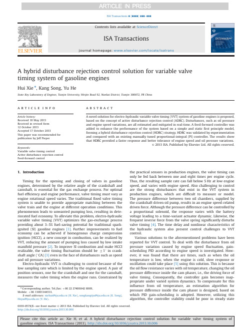
A hybrid disturbance rejection control solution for variable valvetiming system of gasoline enginesHui Xie n,Kang Song,Yu HeState Key Laboratory of Engines,Tianjin University,Weijin Road92,Nankai District,Tianjin300072,PR Chinaa r t i c l e i n f oArticle history:Received10May2013Received in revised form12October2013Accepted17October2013This paper was recommended forpublication by Jeff PieperKeywords:Variable valve timing controlActive disturbance rejection controlFeed-forward controla b s t r a c tA novel solution for electro-hydraulic variable valve timing(VVT)system of gasoline engines is proposed,based on the concept of active disturbance rejection control(ADRC).Disturbances,such as oil pressureand engine speed variations,are all estimated and mitigated in real-time.A feed-forward controller wasadded to enhance the performance of the system based on a simple and staticfirst principle model,forming a hybrid disturbance rejection control(HDRC)strategy.HDRC was validated by experimentationand compared with an existing manually tuned proportional-integral(PI)controller.The results showthat HDRC provided a faster response and better tolerance of engine speed and oil pressure variations.&2013ISA.Published by Elsevier Ltd.All rights reserved.1.IntroductionTiming for the opening and closing of valves in gasolineengines,determined by the relative angle of the crankshaft andcamshaft,is essential for the gas exchange process.For optimalfuel efficiency and engine performance,valve timing must vary asengine rotational speed varies.The traditionalfixed valve timingsystem is unable to provide appropriate matching between thevalve train and the engine at different operation conditions.Thisphenomenon leads to unwanted pumping loss,resulting in dete-riorated fuel economy.To alleviate this problem,electro-hydraulicvariable valve timing(VVT)optimizes the gas-exchange processproviding about3–5%fuel-saving potential for traditional spark-ignited(SI)gasoline engines[1].Further improvements to fueleconomy can be achieved if homogenous charge compressionignition(HCCI),a new concept in combustion,can be realized byVVT,reducing the amount of pumping loss caused by low intakemanifold pressure[2].To improve SI combustion and make HCCIrealizable,the valve timingfluctuation should be711in crank-shaft angle(1CA)[3]even in the face of disturbances such as speedand oil pressure variations.Electro-hydraulic VVT is challenging to control because of thelow sampling rate which is limited by the engine speed.A pair ofposition sensors,one for the crankshaft and one for the camshaft,measures the valve timing when the engine runs.Constrained bythe practical sensors in production engines,the valve timing canonly be fed back between one and eight times per engine cycle.Thus,the resulting sample rate can fall below5Hz at low enginespeed,and varies with engine speed.Also challenging to controlare the strong disturbances that exist in the VVT system inproduction engines,which are difficult to measure or model.The pressure difference between two oil chambers,supplied bythe crankshaft driven oil pump,results in an engine speed-relateddriven force.Although the pressure difference can be controlled bya proportional solenoid,the response varies with the batteryvoltage leading to a time-variant actuator dynamic.Likewise,thefrequent inverse force from the valve spring significantly disturbsvalve timing[4].The time delay and nonlinear characteristics ofthe hydraulic system also present control challenges to VVTcontrol.Various solutions to the aforementioned problems have beenreported for VVT control.To deal with the disturbance from oilpressure variation caused by engine speedfluctuation,gain-scheduling PID according to engine speed is investigated.How-ever,it was found that there are times,such as when the oiltemperature is low,when the engine is cold,slow response oroscillation could take place[5]using this solution.This is becausethe oilflow resistance varies with oil temperature,changing the oilpressure difference inside the cam phaser,i.e.,the driving force ofvalve timing.Consequently,the controller gain becomes inap-propriate under varied system dynamics.To compensate for thisinfluence from oil temperature,an estimation algorithm forpressure difference inside the cam phaser is designed,based onwhich PID gain-scheduling is adopted.However,utilizing thisalgorithm,the controller stability could be poor in steady stateContents lists available at ScienceDirectjournal homepage:/locate/isatransISA Transactions0019-0578/$-see front matter&2013ISA.Published by Elsevier Ltd.All rights reserved./10.1016/j.isatra.2013.10.006n Corresponding author.Tel./fax:þ8622274068428009,Mobile:þ8613001344531.E-mail addresses:xiehui@(H.Xie),songkangtju@(K.Song),Heyu@(Y.He).ISA Transactions∎(∎∎∎∎)∎∎∎–∎∎∎condition if the controller gain is set very large to improve the response in the transient state [6].Accordingly,a PID gain-switching solution based on steady and transient state detection is proposed [6].Although these kinds of controllers can compen-sate for the disturbances,such as the engine speed,oil pressure,as well as oil temperature,they usually require time-consuming parameter optimization.Another possible choice is to use feed-forward control based on various kinds of models such as the neural network model [7],the discrete nonlinear model [8],and the power-oriented graphs (POG)model [9].However,these models are usually too complex for an engine control unit (ECU)application due to the computational burden upon the processor.To summarize,the dilemma is between the strong distur-bances,the low sampling rate,and the limited disturbance rejec-tion ability of existing PI controllers.Gain-scheduling PI control and dynamic model based feed-forward control can alleviate the dilemma,but suffer from time-consuming parameter optimization limiting their appeal for practical application.In this paper,a new solution is presented based on the active disturbance rejection control (ADRC)concept [10–13]that has been widely used in many fields [14–16].The engine speed,oil pressure,and battery voltage fluctuations of the VVT system are all treated as disturbances and are observed and canceled in real-time.Applying the parameterization method in [17]allows for an easy and intuitive tuning process.However,the control perfor-mance was limited due to the limited bandwidth.Feed-forwardcontrol was found to be effective in improving ADRC performance [18].Therefore,to speed up the system,a simple static first principle model of the VVT system was used to design a feed-forward controller forming a hybrid disturbance rejection control (HDRC)strategy.Experimental results of HDRC and an existing manually tuned PI controller were obtained to evaluate the effectiveness of HDRC for the VVT system.This paper is organized as follows:The VVT operation principle is described in Section 2.The HDRC strategy is presented in Section 3.Experimental validations on the VVT test bed are given in Section 4,with concluding remarks in Section 5.2.Basic principle of the electro-hydraulic VVT system 2.1.VVT structureThe VVT system in this study is a typical electro-hydraulic system as shown in Fig.1.The cam phaser housing is connected with the crankshaft,while the rotor is connected with the camshaft.The relative angle between the two shafts,denoted as the valve timing,is determined by the relative position of the housing and the rotor.Between the housing and the rotor,there are two oil chambers.The oil pressure differences between the chambers can be used to control the valve timing,forward orbackward.H.Xie et al./ISA Transactions ∎(∎∎∎∎)∎∎∎–∎∎∎22.2.Valve timing detectionThe camshaft and crankshaft position sensors are used for valve timing detection,producing the output signals for two complete revolutions as demonstrated by Fig.2.The valve timing can then be calculated by analyzing the relative angle between the starting sequences of these two signals.Consequently,the sampling rate is limited between one and eight times per engine cycle.In this study,it is chosen to be once per engine cycle for simplicity.2.3.Valve timing controlAs mentioned in Section 2.1,the valve timing is controlled by the oil pressure difference between the housing and the rotor,which is adjusted by regulating the oil flow rate and direction by use of a proportional solenoid.The position of the proportional solenoid is controlled by a two-stage pulse-width modulation (PWM)signal (using 300Hz frequency in this paper)as demon-strated in Fig.3.The first stage is called driving-stage where the duty cycle of the signal is either 100%or 0%causing the core of the solenoid to beat one of its limits.In this condition,the oil flowsinto or out of the oil chamber,which can push or pull the rotor of the cam phaser to adjust the valve timing.The second stage is valve timing holding stage where the duty cycle is between 45%and 70%so the core of the solenoid is in the middle where almost no oil flows into or out of the cam phaser.In this condition,the valve timing can be partially maintained for a short period.Accordingly,the typical response pro file within one control cycle consists of three stages as demonstrated in Fig.3–delay,quasi-uniform motion,and valve timing holding.This response pro file can be adjusted by the two-stage PWM signal through the adjustment of the driving-stage time fraction T driving =T Cycle ,where T driving is the time duration of the driving-stage signal,T Cycle is the time duration of one engine cycle and the holding-stage duty cycle.For example,the “quasi-uniform motion ”stage extends with T driving =T Cycle increasing,which could adjust the valve timing.2.4.Experimental benchThe VVT test bench is shown in Fig.4,and consisted of three parts –the simulation engine constructed by a cylinder head and a motor;the lubrication and valve timing driving system which included the oil pump,oil filter,oil heater,oil pressure regulating valve,and oil pipes;and the measurement and control system of an engine control unit (ECU),an industrial personal computer,the oil temperature and pressure sensor,position sensors (for crank-shaft and camshaft),and a proportional solenoid.The VVT cam phaser is a self-developed electro-hydraulic one with the structure shown in Fig.1.The engine speed,oil pressure,and temperature can all be flexibly controlled and measured on this platform.Experimental validation of HDRC was carried out on this platform,explained in detail in Section 4.3.Controller synthesisAs has been analyzed,VVT system is typically a single-input single-output (SISO)system with low sampling rate,delay,and strong disturbances,such as like the fluctuation of oil pressure and temperature,battery voltage,and engine load as illustrated in Fig.5.The goal of this study is to propose a practical solution for VVT control with fast response,high robustness and disturbance rejection ability,having parameters that are easy to tune without requirement for time-consuming gain-scheduling.The idea is to treat all the disturbances,varied system dynamics and external forces fluctuations,as a time-varying state “total disturbance ”,estimated and mitigated in real time by ADRC,assisted by feed-forward controller to enhance the response.Therefore a new solution,HDRC,is proposed and illustrated in Fig.6.The two-stage PWM signal (shown in Fig.3),driving-stage and holding-stage,is synthesized by the “Signal synthesis ”module which takes the engine speed into account,for the purpose of calculating the time duration of one engine cycle T Cycle .The driving-stage signal,determined by ADRC and FF together,is de fined by three parameters –valve timing adjusting direction factor (K direct ),driving-stage signal time duration (T driving )and T cycle ,in which K direct ,a constant equals À1or 1,determines the duty cycle (À1for 0%duty cycle and 1for 100%duty cycle),and T driving =T Cycle de fines the signal time fraction of one engine cycle ranging from 0to 1.For the ADRC module,it treated all uncertain-ties inside the VVT system as total disturbance,estimated and mitigated in real time,producing the first part of the driving-stage signal parameters:K direct _ADRC ÂT driving _ADRC =T Cycle .However,due to the low sampling rate,the performance of ADRC is limited.Therefore,a static first principle model-based feed-forward (FF)controller was designed for the other part of driving-stage para-meters K direct _FF ÂT driving _FF =T Cycle ,in order to speed the systemup.Fig.1.Basic operating principle of electro-magnetic VVTsystem.Fig.2.Valve timing detection principle.0.00.20.40.60.8 1.0025*******D u t y C y c l e (%)Cycle Index0.00.20.40.60.8 1.0204060V a l v e T i m i n g (°C A )Cycle IndexFig.3.Solenoid driving signal and the according response pro file.H.Xie et al./ISA Transactions ∎(∎∎∎∎)∎∎∎–∎∎∎3In regards to the holding-stage signal,the time fraction hasalready been determined as 1ÀT driving =T cycle ,while its duty cycle is controlled by the holding-stage adjustment module,which will be described in detail in Section 3.3.3.1.System modelingIn this study,the VVT system is approximated as an ideal system shown in Fig.7,composing of a solenoid model and a linear hydraulic cylinder model with a spring and damper simu-lating the VVT cam phaser.The valve timing changing speed is approximated by the piston moving speed of the hydraulic cylinder in this model.This solenoid position is assumed to be fully controlled by the PWM duty cycle X v ¼K p ðu Àu m Þð1Þwhere X v is the solenoid position (ranging from À1to 1),K p is the gain between the solenoid position and PWM driving signal duty cycle,u is the PWM duty cycle (ranging from 0%to 100%),and u m is the holding-stage duty cycle around 50%.X v 40indicates that the solenoid moves right and the inlet port (on the left in Fig.8)is open.The oil mass flow rate through the solenoid inlet valve Q L can be estimated as follows:Q L ¼C d ÂW ÂX v ffiffiffiffiffiffiffiffiffiffiffiffiffiffiffiffiffiffiffiffiffiffiffiðP S ÀP 1Þ=ρp ð2Þwhere C d is the flow coef ficient of the solenoid inlet valve,W is the perimeter of the inlet valve,P s is the oil pressure at the outletport of the oil pump,P 1is the oil pressure in the high pressure oil chamber,and ρis the oil density.The oil mass flow rate into and out of the solenoid can also be estimated according to the continuity equation,supposing that the modulus of elasticity is constant,the oil pressure distribution is homogeneous,the leakage flow within the oil chamber and out of the chamber is laminar,and the pressure dynamic in the oil pipe between the solenoid and cam phaser can be neglected.Thus,the oil mass flow into and out of the oil chamber can be estimated as follows:Q 1¼A pdx p dt þC ip ðP 1ÀP 2ÞþC ep P 1þV 1βεdP 1dt ð3ÞQ 2¼A p dx p þC ip ðP 1ÀP 2ÞÀC ep P 2þV 2βεdP 2ð4Þwhere Q 1is the oil mass flow rate into the oil chamber through the solenoid inlet valve from the pump,A p is the effective sectional area of the piston,x p is the piston displacement,C ip is the leakage coef ficient of the crevice between the piston and the chamber,C ep is the leakage coef ficient of the crevice between the piston connection rod and the chamber,βεis the oil effective volumetric modulus of elasticity,and V 1is the high pressure oil chamber volume.Q 2is the oil mass flow rate out of the oil chamber,consisting of the oil through the solenoid inlet valve,leaked through the piston –cylinder liner crevice,and leaked outside the cylinder.P 2is low pressure oil chamber pressure and V 2is the low pressure oil chamber volume.The two equations above are further simpli fied based on two assumptions.The oil is assumed to be incompressible (where ðV 1=βεÞðdP 1=dt Þ¼0).Likewise,the internal leakage can be ignored when compared with the external one (so C ip ðP 1ÀP 2Þ⪡C ep P 1,where P 2is atmospheric pressure,P 1¼εÂP s with εa constant,Q 1%Q L ).Therefore,the following equation can be obtained:Q L ¼A pdx pdtþϵÂC ep ÂP S ¼A p v þϵC ep P S ð5Þwhere v is the moving speed of thepiston.Fig.4.Experimental bench con figuration.Fig.5.Control problem description of VVT system.H.Xie et al./ISA Transactions ∎(∎∎∎∎)∎∎∎–∎∎∎4The following equation can be made by analyzing the force produced by the oil pressure difference:A p ðP 1ÀP 2Þ¼m t d 2x p dtþB p dx pdt þK S x p þF Load ð6Þwhere m t is the equivalent mass of the engine piston and valve,B p is the viscous damping coef ficient of the piston,K s is the stiffness of the spring,and F Load is the external force from the valve.The equation above can be approximated by A p ðP 1ÀP a Þ¼Fð7Þwhere F is an equivalent force of all the right side elements in Eq.(6),and P a is the atmospheric pressure.Finally,the static model for the cam phaser motion speed estimation is achieved as follows:v ¼K p C d W ffiffiffiffiffiffiffiffiffiffiffiffiffiffiffiffiffiffiffiffiffiffiffiffiffiffiffiffiffiffiffiffiffiffiffiffiffiffiffiffiffiðP S ÀðF =A p ÞÀP a Þ=ρp Âðu Àu m ÞÀϵC ep P S A p ð8Þwhere K p ,C d ,F ,and C ep can be estimated with a detailed simulation model [19].W ,P s and A p can be measured or calculated directly.3.2.Active disturbance rejection controlBased on the model illustrated as Eq.(8)in Section 3.1,the VVT system can be approximated by a simple first order system as demonstrated in the following equation:υ¼_y ¼w e þ½K p C d W ffiffiffiffiffiffiffiffiffiffiffiffiffiffiffiffiffiffiffiffiffiffiffiffiffiffiffiffiffiffiffiffiffiffiffiffiffiffiðP s ÀF =A p ÀP a Þ=ρq Âðu Àu m ÞÀϵC ep P s =A p¼w e À½k p C d W ffiffiffiffiffiffiffiffiffiffiffiffiffiffiffiffiffiffiffiffiffiffiffiffiffiffiffiffiffiffiffiffiffiffiffiffiffiffiðP s ÀF =A p ÀP a Þ=ρq Âu mþϵC ep P s =A p þk p C d W ffiffiffiffiffiffiffiffiffiffiffiffiffiffiffiffiffiffiffiffiffiffiffiffiffiffiffiffiffiffiffiffiffiffiffiffiffiffiðP s ÀF =A p ÀP a Þ=ρq =A p u¼w e À½k p C d W ffiffiffiffiffiffiffiffiffiffiffiffiffiffiffiffiffiffiffiffiffiffiffiffiffiffiffiffiffiffiffiffiffiffiffiffiffiffiðP s ÀF =A p ÀP a Þ=ρq Âu mþϵC ep P s =A p þ½k p C d W ffiffiffiffiffiffiffiffiffiffiffiffiffiffiffiffiffiffiffiffiffiffiffiffiffiffiffiffiffiffiffiffiffiffiffiffiffiffiðP s ÀF =A p ÀP a Þ=ρq =A p Àb 0 u þb 0u ¼f þb 0uð9Þwhere y is the valve timing,υis the moving speed of the piston(used to approximate the changing speed of the valve timing _y),w e is the external disturbance,b 0is an approximate value (49is used in this paper)of k p C d W ffiffiffiffiffiffiffiffiffiffiffiffiffiffiffiffiffiffiffiffiffiffiffiffiffiffiffiffiffiffiffiffiffiffiffiffiffiffiðP s ÀF =A p ÀP a Þ=ρp =A p at a fixed operating point (3.5bar oil pressure,401C oil temperature in this paper),and f is referred as the total disturbance as shown in the following equation:f ¼w e À½k p C d W ffiffiffiffiffiffiffiffiffiffiffiffiffiffiffiffiffiffiffiffiffiffiffiffiffiffiffiffiffiffiffiffiffiffiffiffiffiffiðP s ÀF =A p ÀP a Þ=ρq Âu m þϵC ep P s =A pþ½k p C d W ffiffiffiffiffiffiffiffiffiffiffiffiffiffiffiffiffiffiffiffiffiffiffiffiffiffiffiffiffiffiffiffiffiffiffiffiffiffiðP s ÀF =A p ÀP a Þ=ρq =A p Àb 0 Âu ð10ÞThe idea of ADRC is to have f estimated and canceled;leaving an integral plant that can be easily controlled.To do so,we first-200204060 Actual EstimatedV a l v e T i m i n g (°C A )-80-4004080 Actual Estimatedf565860626466687020406080100D u t y C y c l e (%)Time (sec)56586062646668705658606264666870Fig.8.LESO validation at 1200rpm engine speed and 1.0bar oilpressure.Fig.7.Simpli fied model of the VVTsystem.Fig.6.Control structure of HDRC.H.Xie et al./ISA Transactions ∎(∎∎∎∎)∎∎∎–∎∎∎5convert the differential equation into an extended state space form _x 1¼x 2þb 0u _x 2¼h y ¼x18><>:ð11Þ_x ¼Ax þbu þEh y ¼Cx(ð12Þwith x 2¼f added as an augmented state,h ¼_funknown,and A ¼0100;B ¼b 00 ;C ¼½10 ;E ¼01 .This allows the construction of a linear extended state observer(LESO)in the form of _z¼Az þbu þL ðy À^y Þy ¼Cz (ð13Þwith L being the observer gain vector and z ¼½z 1;z 2; T being the estimated states.In other words,z 2is obtained in real-time as the approximation of f in Eq.(9),and the control law u ¼ðÀz 2þu 0Þ=b 0¼K direct _ADRC ÂT driving _ADRC =T cycle ranging from À1to 1.Here K direct _ADRC is a constant equals À1or 1,representing the duty cycle of driving-stage signal,i.e.,0%duty cycle when negative,100%duty cycle when positive,and T driving _ADRC is the duration of the driving stage signal calculated from ADRC.Thus,Eq.(9)approximately to _y%u 0which can easily be controlled with a proportional controller u 0¼K p ðr Àz 1Þð14Þwhere r is the setpoint,K p is the proportion gain,and z 1is the estimation of x 1.The observer gain and the P controller parameters can be easily tuned using the parameterization method in [17].The tuning para-meters include the observer bandwidth ωo ,the control bandwidth ωc ,and the physical constant b 0.For the VVT system,ωo is chosen around 5while ωc ranged from about 0.5to 2at 1200rpm engine speed with a sampling rate of 10Hz (sampling every engine cycle,in the meanwhile the crankshaft turns two revolutions).Finally,with the LESO tuned for an operation point of 1200rpm and 3.5bar oil pressure,the system was tested with the oil pressure at 1.0bar (much lower than the normal level)to analyze the disturbance rejection ability of the controller.The result isillustrated in Fig.8with the actual disturbance f ¼_yÀb 0u .Both y and f are estimated but with a small amount of error,especially during the transient process.This has a close relationship with thelow sampling rate (10Hz at 1200r/min engine speed),limiting itsperformance to some extent.3.3.Feed-forward controlTo speed the system up,a feed-forward controller was designed based on the simple static first principle model demonstrated in Eq.(8).The driving stage signal duty cycle and its time fraction in one engine cycle can be calculated by K direct_FF ÂT driving_FF Tcycle¼αÂr ÀyvTcycle ð15Þwhere K direct _FF is a constant,À1or 1,de fining the desired VVT timing adjusting direction.That is,when K direct _FF equals À1,the duty cycle of the driving-stage signal is 0%,and when K direct _FF equals to 1,and the duty cycle should be 100%.T driving _FF is the duration of the driving-stage signal calculated by FF,r is the desired valve timing,y is the actual valve timing,and αis a coef ficient used to tune the weight of the feed-forward controller.The smaller αis the more conservatively the feed-forward controller is used.Here the delay period (the first stage of the output response in Fig.3)is ignored for simplicity.The feed-forward control is actually a gain-scheduled propor-tion control,as the proportion varies with the oil pressure,oil temperature,etc.Therefore,feed-forward control here is an effective improvement of ADRC in the transient process in the case of operating condition variations under limited sampling rate.Finally,the FF controller is integrated with the ADRC controller.Thus,in the transient operating process (when the difference between y and r is over 51CA in this paper),the driving-stage signal becomes K direct T driving =T Cycle ¼K direct _FF T driving _FF =T Cycle þK direct _ADRC T driving _ADRC =T Cycle .The duty cycle (0%or 100%)is deter-mined by the sign of K direct ,a constant equals À1or 1,i.e.,0%duty cycle is selected when K direct equals À1or 100%duty cycle when K direct equals 1.The according time fraction of one engine cycle T driving =T cycle ,ranging from 0?to 1,equals the absolute value of K direct _FF T driving _FF =T Cycle þK direct _ADRC T driving _ADRC =T Cycle .The control performance comparison between the controllers with and without FF was demonstrated in Fig.9.Here,the settling time is de fined as the time duration between the moment when the valve timing order is sent and the moment after which the valve timing error stays within 751CA.It could be noticed that overshoot was reduced with the FF controller,resulting in shor-tened (about 39%)settling time de fined above.It is because the low sampling rate leads to the LESO's slow tracking of both y and f ,0306090120D u t y C y c l e (0-100)Time (sec)02550V a l v e T i m i n g (°C A )151617181920030609012002550D u t y C y c l e (0-100)Time (sec)V a l v e T i m i n g (°C A )Fig.9.Transient performance comparison with and without feed-forward control at 1200rpm engine speed and 3.5bar oil pressure.(a)without feed-forward control and (b)with feed-forward control.H.Xie et al./ISA Transactions ∎(∎∎∎∎)∎∎∎–∎∎∎6making VVT timing overshoot when pursues short rising time.Fortunately,this con flict was alleviated by feed-forward control.3.4.Holding-stage duty cycle adjustmentSince the holding-stage (as shown in Fig.3)usually takes a much larger time fraction of one engine cycle,a small duty cycle error may lead to a large valve timing error,increasing the compensation burden of HDRC.Therefore,an online adjustment algorithm is needed to correct the holding-stage duty cycle DuCy Holding based on the observation of the driving-stage duty cycle DuCy Driving and the valve timing error Δy HoldingCyl cor ¼DuCy Driving ÀDuCy Holdingαð1þβΔy Þð16ÞDuCy Holding ¼DuCy Holding þHoldingCyl cor ð17Þwhere αand βcan be calibrated to tune the compensation speed.This algorithm is disabled when the valve timing goes into a small error band to avoid the small oscillations caused by the algorithm.4.Experimental validationExperimental validations of HDRC were carried out on the VVT control test bed mentioned in Section 2.4,in order to test its robustness to variations of oil pressure and engine speed,and the disturbance rejection ability to the fast oil pressure fluctuation.Three evaluation indexes were proposed to quantify the control performance,including the settling time (in this paper,de fined as the time duration between the moment when the valve timing order is sent and the moment after which the valve timing error stays 751CA,denoted as T s ),the integral time absolute error (ITAE ),as well as the fluctuation amplitude in steady state (θfluct ).First,as a baseline,the control performance comparison of three controllers,the manually tuned PI controller and ADRC controller as well as the HDRC controller,was carried out at 1200rpm,3.5bar oil pressure and 401C oil temperature (the oil temperature is all around 401C in this paper),with the valve timing stepping from 501CA to 101CA as shown in Figs.9and 10,results of which are summarized in Table 1.It can be noticed that ADRC has obvious advantage over PI in terms of faster response (about 21%improvement)and accurate tracking performance (about 56%improvement).With FF,the response speed can be further improved (to about 51.9%compared with PI)as analyzed in Section 3.3but,the tracking precision stays almost the same since FF was disabled in the steady state condition.For the purpose of evaluating the effect of ADRC and FF as a whole,HDRC was systematically compared with a pure PI controller in Sections 4.1and 4.2,at different operating conditions and in face of oil pressure fluctuations,without gain-scheduling for neither of them.4.1.Robustness testVariations of the engine speed and oil pressure,common phenomena in practical engines,can change the sampling rate and the system dynamics signi ficantly.It is,therefore,essential to be robust to these variations for realizable VVT control.So,the HDRC and PI controller were tested at low engine speed (800r/min,in Fig.11)and low oil pressure (2.0bar,in Fig.12)respectively,in505152535455D u t y C y c l e (0-100)Time (sec)02550V a l v e T i m i n g (°C A )Fig.10.50–101CA step test of PI at 1200rpm engine speed and 3.5bar oil pressure.Table 1Control performance comparison between PI,ADRC and HDRC at 1200r/min and 3.5bar oil pressure.T s (ms)ITAE (1CA)θfluct (1CA)PI 102815.1 1.8ADRC 81413.80.8HDRC49412.30.6414243444546030609012002550D u t y C y c l e (0-100)Time (sec)V a l v e T i m i n g (°C A )2728293031320306090120D u t y C y c l e (0-100)Time (sec)02550V a l v e T i m i n g (°C A )Fig.11.Control performance comparison between PI and HDRC with 50–101CA step at 800rpm engine speed and 3.5bar oil pressure,(a)HDRC controller and (b)PI controller.H.Xie et al./ISA Transactions ∎(∎∎∎∎)∎∎∎–∎∎∎7。

基于VB软件的汽车传动系参数计算王华【摘要】利用Visual Basic6.0和Microsoft Excel软件工具,开发出了汽车传动系最小和最大传动比参数优化模块.首先介绍了设计最大、最小传动比的理论,再用Excel软件处理发动机特性数据,拟合"最小燃油消耗率"曲线,然后利用VB软件调用Excel表中的曲线系数,计算最小传动比,考虑了经济型,在设计最大传动比时又兼顾了动力性.【期刊名称】《兰州工业学院学报》【年(卷),期】2017(024)006【总页数】5页(P71-75)【关键词】传动比;最小燃油消耗;Excel;VB【作者】王华【作者单位】安徽工业经济职业技术学院机械与汽车工程学院,安徽合肥 230051【正文语种】中文【中图分类】TP312;U462.3传动系参数的确定在汽车的优化设计中占有一定地位,最小传动比和最大传动比的选定对动力性和经济性都有一定影响.汽车大多数时间使用高挡位行驶,因此传动系最小传动比的选定很重要,传动比过大会使汽车后备功率增大,这样动力性较好,但是燃油经济性较差;如果传动比过小会使燃油经济性较好,但动力性会变差,因此汽车传动系的最小传动比需要合理选择才能兼顾两者的性能.确定最大传动比时要考虑3方面的问题:最大爬坡度、附着率和最低稳定车速.本文利用EXCEL数据处理软件和Visual Basic6.0编程软件设计并计算出最小和最大传动比.就普通汽车而言,传动系总的传动比是传动系中各部件传动比的乘积[1],即it=ig·io.式中,it为总传动比;ig为变速器的传动比;i0为主减速器的传动比.普通汽车如果直接挡为最高挡时,传动系的最小传动比就是主传动比,即itmin=io;如果最高挡为超速挡时,最小传动比为变速器最高挡传动比igmin与主传动比的乘积,即itmin=igmin·io.在求解传动系传动比时还需要利用发动机转速n和汽车行驶速度u之间的关系u=0.377.式中,r为车轮半径;n为发动机转速,由最小燃油消耗特性得到n=f(p);p为功率.最小传动比igminio=0.377.在公式(3)中转速与功率的关系通过“最小燃油消耗率”曲线获得,即n=f(p).而发动机发出的功率p等于机械传动损失功率与全部运动阻力所消耗的功率,如图1,最大速度与功率的关系p=(+).式中,G为汽车重力;f为摩擦系数;CD为风阻系数;A为迎风面积.由公式(3~5)可以得到最小传动比.传动系最大传动比是变速器1挡传动比与主传动比的乘积,当主传动比已知时,确定传动系最大传动比也就是确定变速器1挡传动比.汽车爬大坡时车速很低,可忽略空气阻力,汽车的最大驱动力应为Ftmax=Ff+Fimax ,即ig1i0≥.式中,Ff为滚动阻力;Fimax为最大坡度阻力;∂max为最大爬坡度(一般货车约30%,轿车常大于30%);Ttmax为发动机最大扭矩;η为传动效率.如果设计越野汽车传动系时,最大传动比应保证汽车能在极低车速umin下稳定行驶,即igmax=0.377.Microsoft Excel 可以进行大量的数据处理、统计分析操作,是微软办公套装软件的一个重要的组成部分,被广泛应用于管理、统计财经、金融等众多领域.本文选择使用Excel计算、分析表格中的数据和制作数据资料图表的功能,还可以选择应用Excel中大量的公式函数.首先,使用Excel强大的数据处理能力处理发动机的转速、功率以及燃油消耗率的万有特性图数据,生成所需要的曲线图[2-3];其次,将每一条曲线添加趋势线公式,对曲线求导数,得到每条曲线的最小值,并将这些最小值数据保存在单元格中;再次,将这些最小值数据生成“最低燃油消耗率”曲线,即发动机最经济工况的情况,如图2,这条曲线表明了在最经济工况运转的发动机提供的功率与转速之间的关系.最后,利用Excel得出最经济工况下转速与功率的关系n=f(p)(如图3),将此函数的系数保存进单元格中.f(p)=anpn+an-1pn-1+…+a1p+a0.式中,an,an-1…a0为多项式的系数;p为功率.有了发动机的“最小燃油消耗特性”,就可以确定传动比与发动机转速以及行驶速度之间的关系.再将函数值带入公式(3),继而求出最经济工况下的最小传动比,同理,利用此方法可以带入公式(7)而求解出最大传动比.Visual Basic是微软公司开发的编程设计软件,它也是基于 Windows操作系统的可视化编程环境.Visual Basic 6.0 操作简单实用,所以从其问世以来很受专业程序员和编程爱好者的追捧.首先利用Visual Basic 6.0软件设计传动比的模块,开发的界面如图4~5所示.其次,利用Visual Basic 6.0软件调用Excel工作表的最小燃油消耗特性值. 本文列出了VB调用Excel工作表中数值的步骤及调用程序部分代码(表1).1) 定义各参数:速度u,功率P,转速n,主传动比i0等;2) 使用VB软件打开Excel工作簿某一个工作表,调用最低燃油消耗特性曲线的系数;3) 将调用的系数代入公式(3~7)中.最后,根据汽车理论的相关公式,计算最小传动比和最大传动比,输出结果并保存. 已知某发动机万有特性图的数据和整车参数(表2),下面根据汽车理论来设计传动系的最小传动比和最大传动比,其方法和步骤如下:1) Excel软件处理万有特性图数据,生成便于设计参数的曲线图.将某发动机的万有特性图中的燃油消耗率、功率和转速数据处理,生成各曲线图如图6所示,从图中可以清楚地看出某一转速下,发动机的功率和燃油消耗率的情况.2) 添加各趋势线公式.Excel表中选择“添加趋势线”功能,在趋势线类型中选择“多项式”选项并显示公式,可以将每一条曲线添加多项式公式(一元二次方程式). 从图中可以看出每条曲线的最低点处即为发动机在某一转速下油耗最低点,也就是最经济的点,此时发动机经济性最好[4-5].3) 求解曲线的最低点.有了趋势线公式就可以求解每条曲线的斜率,得到曲线的最低点,本文用MATLAB软件来求解,将最低点数据保存在单元格中.① 利用MATLAB软件求解每条曲线的最低点,代码如下.>>f=sym('a*x^2+b*x+c') 定义函数表达式(x-功率;f-油耗率)f =a*x^2+b*x+c>> diff(f) 对变量x求一阶微分ans =2*a*x+b 得出一阶导数表达式>>solve('2*a*x+b ','o') 求解曲线的最小值② Excel求解最小值Excel软件中的LINEST函数将每条拟合曲线的公式系数写入单元格,拟合公式f(p)=a2p2+a1p+a0,三个系数分别为a2 ,a1 和a0 .a2=INDEX(LINEST(Sheet1!C2:C14,A2:A14^{1,2},TRUE,TRUE),1,1)a1=INDEX(LINEST(Sheet1!C2:C14,A2:A14^{1,2},TRUE,TRUE),1,2)a0=INDEX(LINEST(Sheet1!C2:C14,A2:A14^{1,2},TRUE,TRUE),1,3)(本例中某条曲线的Y值区域从C2:C14,X值区域从A2:A14)再利用一阶导数即f(p)=2a2p+a1=0求解出最小值,并保存在单元格中.4) Excel将这些最低点拟合曲线得到“包络线”,即最低燃油消耗率曲线.这条曲线即最经济工况下转速与功率的关系曲线,如图7,也给它添加趋势线公式,这样就可以求任何功率所对应的经济转速n=f(P).5) 保存公式系数.Excel软件中的LINEST函数将最低燃油消耗率曲线公式n=f(P)中的系数写入各个单元格,保存,以备VB软件调用.6) VB软件调用Excel表数据并计算.在VB界面分别输入整车参数、最大速度、最大爬坡度、主传动比等,程序会调用Excel表中相关系数,并带入相关公式就可以计算出最小、最大传动比,计算结果如表3所示.最大传动比计算出来以后,还应该计算驱动轮的附着率,检查是否满足爬坡或加速能力.设计出最小和最大传动比后,厂家可根据挡位和实际需要再设计中间挡位的传动比,一般汽车传动系各挡的传动比大体上是按照等比级数分配的,主要目的是充分利用发动机提供的功率,提高动力性.本文介绍的传动系参数的计算方法,为使结果精确,一开始在使用Excel处理发动机的数据时,最好由发动机厂家提供准确的离散数据,这样在拟合曲线时误差会小很多,优化的结果会更精确些.【相关文献】[1] 余志生.汽车理论[M]. 5版.北京:机械工业出版社,2016:30-84.[2] 张乃平. Visual Basic处理Excel表格的编程[J]. 电脑编程技巧与维护,2016(4):73-74.[3] 杨晓春,丁一. 基于VB/Excel的数据报表生成及打印功能实现方法[J]. 河北能源职业技术学院学报,2015(2):73-74,78.[4] 王佳. 基于VC++的重型载货汽车传动系参数优化与匹配软件设计[J]. 兰州工业学院学报,2016(3):62-66.[5] 胡昌佐,邓旻涯,杨汉乾. 皮卡传动系统参数优化匹配研究[J]. 企业技术开发,2017(2):13-16.。

柴油发动机喷射系统外文文献翻译、中英文翻译、外文翻译In the past five years。
there has been a XXX。
with the most significant change being the use of common rail XXX n diesel engines。
which is now receiving increasing n。
While there is also a trend towards direct XXX engines。
this XXX。
such as air n。
XXX.Keywords: fuel supply system。
common rail system。
XXX.The most basic n of any fuel oil supply system is to XXX。
XXX increase in vehicle n requirements。
precise control of the system has XXX。
the fuel oil supply system should not only change the cycle oil but also adjust the XXX.In the mid-90s。
carburetor XXX。
but the control aspect was not accurate。
After many improvements。
the carburetor was able to control each XXX and full XXX。
XXX。
XXX。
and XXX.XXX was common in the early 90s。
timing XXX improvement。
This led to the development of XXX driving。
pushing forward the European XXX.From the fuel system's point of view。
用VB和Excel实现调节级特性曲线
牛卫东;孙玉明
【期刊名称】《山东电力技术》
【年(卷),期】2002(000)005
【摘要】在进行汽轮机的变工况计算时,通常要用到调节级的相关特性曲线,本文利用VB语言和Excel实现了N300MW机组调节的特性曲线.
【总页数】3页(P66-68)
【作者】牛卫东;孙玉明
【作者单位】250002,山东电力研究院;272000,山东莱芜发电厂
【正文语种】中文
【中图分类】TK262
【相关文献】
1.基于VB-Excel的P-Ⅲ曲线可视化研究与实现 [J], 叶荣波;杜廷娜;赵海峰;赵海波
2.EXCEL调用MATLAB实现风机特性曲线拟合 [J], 吴劭星;谢贤平;杨会明
3.汽轮机调节级特性曲线快速算法改进 [J], 李慧君;赵翔
4.用VB控制Origin实现船舶航行特性曲线的自动绘制 [J], 张宗科
5.船用湿汽轮机调节级特性曲线算法改进 [J], 陆英栋;杨自春;曹跃云;张磊
因版权原因,仅展示原文概要,查看原文内容请购买。
南京理工大学紫金学院毕业设计(论文)外文资料翻译系:机械系专业:车辆工程专业姓名:宋磊春学号:070102234外文出处:EDU_E_CAT_VBA_FF_V5R9(用外文写)附件:1。
外文资料翻译译文;2.外文原文.附件1:外文资料翻译译文CATIA V5 的自动化CATIA V5的自动化和脚本:在NT 和Unix上:脚本允许你用宏指令以非常简单的方式计划CATIA。
CATIA 使用在MS –VBScript中(V5.x中在NT和UNIX3。
0 )的共用部分来使得在两个平台上运行相同的宏。
在NT 平台上:自动化允许CATIA像Word/Excel或者Visual Basic程序那样与其他外用分享目标。
ATIA 能使用Word/Excel对象就像Word/Excel能使用CATIA 对象。
在Unix 平台上:CATIA将来的版本将允许从Java分享它的对象。
这将提供在Unix 和NT 之间的一个完美兼容。
CATIA V5 自动化:介绍(仅限NT)自动化允许在几个进程之间的联系:CATIA V5 在NT 上:接口COM:Visual Basic 脚本(对宏来说),Visual Basic 为应用(适合前:Word/Excel ),Visual Basic。
COM(零部件目标模型)是“微软“标准于几个应用程序之间的共享对象。
Automation 是一种“微软“技术,它使用一种解释环境中的COM对象。
ActiveX 组成部分是“微软“标准于几个应用程序之间的共享对象,即使在解释环境里。
OLE(对象的链接与嵌入)意思是资料可以在一个其他应用OLE的资料里连结并且可以被编辑的方法(在适当的位置编辑).在VBScript,VBA和Visual Basic之间的差别:Visual Basic(VB)是全部的版本。
它能产生独立的计划,它也能建立ActiveX 和服务器。
它可以被编辑。
VB中提供了一个补充文件名为“在线丛书“(VB的5。
汽车发动机外文翻译文献(文档含中英文对照即英文原文和中文翻译)AUTOMOTIVE ENGINE1 Engine Classification and Overall MechanicsThe automobile engines can be classified according to: (1) cycles, (2) cooling system, (3) fuel system, (4) ignition method, (5) valve arrangement, (6) cylinder arrangement, (7) engine speed.Engines used in automobiles are the internal combustion heat engines. The burning of gasoline inside the engine produces high pressure in the engine combustionchamber. This high pressure force piston to move, the movement is carried by connecting rods to the engine crankshaft. The crankshaft is thus made to rotate: the rotary motion is carried through the power train to the car wheels so that they rotate and the car moves.The engine requires four basic systems to run (Fig. 2-1). Diesel engines require three of these systems. They are fuel system, ignition system (except diesel), lubricating system and cooling system. However, three other related systems are also necessary. These are the exhaust system, the emission-control system, and the starting system. Each performs a basic job in making the engine run.Fig. 2-1 The engine construction2 Engine Operating PrinciplesFig. 2-2 Engine termsThe term “stroke” is used to describe the movement of the piston within the cylinder. The movement of the piston from its uppermost position (TDC, top dead center) to its lowest position (BDC, bottom dead center) is called a stroke. The operating cycle may require either two or four strokes to complete. Most automobile engines operate on the four stroke cycle (Fig. 2-2).In four-stroke engine, four strokes of the piston in the cylinder are required tocomplete one full operating cycle. Each stroke is named after the action. It performs intake, compression, power, and exhaust in that order (Fig. 2-3).Intake stroke Compression stroke Power stroke Exhaust strokeFig. 2-3 Four-stroke-cycle gasoline engine1. The intake strokeThe intake stroke begins with the piston near the top of its travel. As the piston begins its descent, the exhaust valve closes fully, the intake valve opens and the volume of the combustion chamber begins to increase, creating a vacuum. As the piston descends, an air/fuel mixture is drawn from the carburetor into the cylinder through the intake manifold. The intake stroke ends with the intake valve close just after the piston has begun its upstroke.2. Compression strokeAs the piston is moved up by the crankshaft from BDC, the intake valve closes. The air/fuel mixture is trapped in the cylinder above the piston. Future piston travel compresses the air/fuel mixture to approximately one-eighth of its original volume (approximately 8:1 compression ratio) when the piston has reached TDC. This completes the compression stroke.3. Power strokeAs the piston reaches TDC on the compression stroke, an electric spark is produced at the spark plug. The ignition system delivers a high-voltage surge of electricity to the spark plug to produce the spark. The spark ignites, or sets fire to, the air/fuel mixture. It now begins to burn very rapidly, and the cylinder pressure increases to as much as 3-5MPa or even more. This terrific push against the piston forces it downward, and a powerful impulse is transmitted through the connecting rod to the crankpin on the crankshaft. The crankshaft is rotated as the piston is pushed down by the pressure above it.4. Exhaust strokeAt the end of the power stroke the camshaft opens the exhaust valve, and the exhaust stroke begins. Remaining pressure in the cylinder, and upward movement of the piston, force the exhaust gases out of the cylinder. At the end of the exhaust stroke, the exhaust valve closes and the intake valve opens, repeating the entire cycle of events over and over again.3 Engine Block and Cylinder Head3.1 Engine BlockThe engine block is the basic frame of the engine. All other engine parts either fit inside it or fasten to it. It holds the cylinders, water jackets and oil galleries (Fig. 2-4). The engine block also holds the crankshaft, which fastens to the bottom of the block. The camshaft also fits in the block, except on overhead-cam engines. In most cars, this block is made of gray iron, or an alloy (mixture) of gray iron and other metals, such as nickel or chromium. Engine blocks are castings.Fig. 2-4 V6 engine blockSome engine blocks, especially those in smaller cars, are made of cast aluminum. This metal is much lighter than iron. However, iron wears better than aluminum. Therefore, the cylinders in most aluminum engines are lined with iron or steel sleeves. These sleeves are called cylinder sleeves. Some engine blocks are made entirely of aluminum.3.2 Cylinder SleevesCylinder sleeves are used in engine blocks to provide a hard wearing material for pistons and piston rings. The block can be made of one kind of iron that is light and easy to cast while the sleeves uses another that is better able to stand up wear and tear. There are two main types of sleeves: dry and wet (Fig. 2-5).Dry sleeve Wet sleeveFig. 2-5 Cylinder sleeve3.3 Cylinder HeadThe cylinder head fastens to the top of the block, just as a roof fits over a house. The underside forms the combustion chamber with the top of the piston. In-line engine of light vehicles have just one cylinder head for all cylinders; larger in-line engines can have two or more. Just as with engine blocks, cylinder heads can be made of cast iron or aluminum alloy. The cylinder head carries the valves, valve springs and the rockers on the rocker shaft, this part of valve gear being worked by the pushrods. Sometimes the camshaft is fitted directly into the cylinder head and operates on the valves without rockers. This is called an overhead camshaft arrangement.3.4 GasketThe cylinder head is attached to the block with high-tensile steel studs. The joint between the block and the head must be gas-tight so that none of the burning mixture can escape. This is achieved by using cylinder head gasket. Gaskets are also used to seal joins between the other parts, such as between the oil pan, manifolds, or water pump and the blocks.3.5 Oil PanThe oil pan is usually formed of pressed steel. The oil pan and the lower part of cylinder block together are called the crankcase; they enclose, or encase, thecrankshaft. The oil pump in the lubricating system draws oil from the oil pan and sends it to all working parts in the engine. The oil drains off and run down into the pan. Thus, there is a constant circulation of oil between the pan and the working parts of the engine.4 Piston Assembly, piston rings , The piston pin ,Connecting Rods, Crankshafts And Flywheel4.1 PistonPiston rings and the piston pin are together called the piston assembly (Fig. 2-6).Fig. 2-6 Piston, piston rings and connecting rodThe piston is an important part of a four-stroke cycle engine. Most pistons are made fr om cast aluminum. The piston, through the connecting rod, transfers to the crankshaft the force created by the burning fuel mixture. This force turns the crankshaft.To withstand the heat of the combustion chamber, the piston must be strong. It also must be light, since it travels at high speeds as it moves up and down inside the cylind er. The piston is hollow. It is thick at the top where it takes the brunt of the heat and th e expansion force. It is thin at the bottom, where there is less heat. The top part of the piston is the head, or crown. The thin part is the skirt. Most pistons have three ring gro oves at the top. The sections between the ring grooves are called ring lands.4.2 piston ringspiston rings fit into ring grooves near the top of the piston. In simplest terms, pisto n rings are thin, circular pieces of metal that fit into grooves in the tops of the pistons. In modern engines, each piston has three rings. (Piston in older engines sometimeshad four rings, or even five.) The inside surface of the ring fits in the groove on the pi ston. The ring's outside surface presses against the cylinder walls. Rings provide the n eeded seal between the piston and the cylinder walls. That is, only the rings contact th e cylinder walls. The top two rings are to keep the gases in the cylinder and are called compression rings. The lower one prevents the oil splashed onto the cylinder bore fro m entering the combustion chamber, and is called an oil ring.4.3 The piston pinThe piston pin holds together the piston and the connecting rod. This pin fits into th e piston pin holes and into a hole in the top end of the connecting rod. The top end of t he rod is much smaller than the end that fits on the crankshaft. This small end fits insi de the bottom of the piston. The piston pin fits through one side of the piston, through the small end of the rod, and then through the other side of the piston. It holds the rod firmly in place in the center of the piston. Pins are made of high-strength steel and hav e a hollow center. Many pins are chrome-plated to help them wear better.A piston pin fits into a round hole in the piston. The piston pin joins the piston to the connecting ro d. The thick part of the piston that holds the piston pin is the pin boss.4.4 Connecting RodsThe connecting rod little end is connected to the piston pin. A bush made from a soft metal, such as bronze, is used for this joint. The lower end of the connecting rod f its the crankshaft journal. This is called the big end. For this big-end bearing, steel-ba cked lead or tin shell bearings are used. These are the same as those used for the main bearings. The split of the big end is sometimes at an angle, so that it is small enough t o be withdrawn through the cylinder bore. The connecting rod is made from forged all oy steel.4.5 CrankshaftsThe crankshaft is regarded as the “backbone” of the engine (Fig. 2-7). The crankshaft, in conjunction with the connecting rod, converts the reciprocating mo tion of the piston to the rotary motion needed to drive the vehicle. It is usually made fr om car-bon steel which is alloyed with a small proportion of nickel. The main bearing journals fit into the cylinder block and the big end journals align with the connecting rods. At the rear end of the crankshaft is attached the flywheel, and at the front end ar e the driving wheels for the timing gears, fan, cooling water and alternator. The throw of the crankshaft, i.e. the distance between the main journal and the big end centers, controls the length of the stroke. The stroke is double the throw, and the strokelength is the distance that the piston travels from TDC to BDC and vice versa.Fig. 2-7 The crankshaft4.6 FlywheelThe flywheel is made from carbon steel. It fits onto the rear of the crankshaft. As well as keeping the engine rotating between power strokes it also carries the clutch, w hich transmits the drive to the gearbox, and has the starter ring gear around its circumf erence. There is only one working stroke in four so a flywheel is needed to drive the c rankshaft during the time that the engine is performing the non-power strokes.5 Valve SystemFig. 2-8 Parts of the valve trainThe valve operating assembly includes the lifters or cam followers, pushrods, rocker arms and shafts or pivot, valve and springs etc. The purpose of this to open and close the intake and exhaust ports that lead to the combustion chambers as required (Fig. 2-8). Valve mechanisms vary depending on the camshaft location. When the camshaft is positioned in the engine block, valve lifters are mounted in the openings above the camshaft. Pushrods are connected from each valve lifter to a pivoted rocker arm mounted above each valve. A lobe on the camshaft is positioned directly below each valve lifter. A typical camshaft drive has a sprocket bolted to the end of the camshaft, and a matching sprocket is attached to the end of the crankshaft. Those two sprockets may be meshed together or surrounded a steel chain to have the camshaft drive. When the lower part of the camshaft lobe is rotating under the valve lifter, the valve spring holds the valve closed.汽车发动机1发动机的分类和整体力学汽车发动机可根据如下因素进行分类:(1)循环系统,(2)冷却系统,(3)燃油系统,(4)点火方式,(5)气门布置,(6)气缸排列,(7)发动机转速。
中英文文献翻译-发动机冷却系统1S u m m a r i z eOutli ne use s a m ore compact desi gn along w ith the engi ne and has in a bi g w ay, the engi ne produces the w aste he at de nsity also obvi ousl y i ncre ases al ong with it. S ome essenti al re gi ons, i f around a row of ty re v al ve radi ate s the questi on to have fi rst to conside r, the cooli ng sy ste m eve n i f appears the small bre akdow n al so possi bl y to cre ate the di saste r in such re gion conse que nce. The e ngi ne cooli ng sy ste m radi ati on ability gene rall y shoul d sati sfy w he n the engi ne full load radi ati on dem and, be cause thi s ti me e ngine produces the quantity of he at is bi g gest. Howe ve r, w he n parti al l oads, the curre nt capacity w hi ch the cooli ng sy ste m can have the powe r loss, whi ch the w ate r pum ping stati on provi des the re fri ge rant current capacity surpasses nee ds. W e hoped starts the starting ti me to be as far as possi ble short. B e cause engi ne ti me di scharges poll utant m ore , the oil consum pti on is also bi g. T he cooling sy stem structure has a m ore tre mendous infl uence to the e ngi ne cold starting ti me.2C h a r a c t e r i s t i c s of m od e r n e n g in e c oo l in g s y s t e mM ode rn e ngi nes serie s characteri sti c tradition cooling sy ste m function reli abl y prote cts the engi ne, but also shoul d have the functi on w hi ch the i mprove ment fuel e conom y and reduces discharges. There fore, the m odern cooli ng sy stem must sy nthesize under the consi deration the factor: Engi ne inte rior fri cti on l oss; C ooli ng syste m w ater pump powe r; B urning boundary conditi on, li ke combusti on cham ber tem pe rature, complete density , complete te mpe rature . The advance d cooling sy ste m uses sy ste m atize d, the modular desi gn method, the ove rall pl an conside re d e ach i nfl ue nce factor, cause s the cooling sy stem both to guarantee the e ngi ne norm al w ork, and enhance s the engi ne e ffi cie ncy and the reducti on di scharge s.2 .1 T h e t e m p e r a t u r e s se t p o in tTempe ratures hy pothe ses fi ring i n bursts m otive operati ng tem pe rature l i mit value are de cide d by a row of tire v al ve the peri pheral re g i on m axi mum tem perature. T he m ost ide al situation is according to the metal tempe rature but is not the refri gerant te mpe rature control cooling sy ste m, like thi s can prote ct the e ngi ne w ell.B ecause the cooling sy ste m hy pothe sis cooli ng te mpe rature i s by the full l oad ti me m ost is bi g i s the foundati on, there fore, engi ne and cooling sy s tem in parti al l oads ti me is at not too the perfe ct conditi on, w hen urban distri ct travel and l ow spee d travel, can have the hi gh oil consumpti on and di scharge. S upposes the fixe d point through the change re fri ge rant tem perature to be possible to i mprove the engine and the cooling sy ste m in parti al l oads time perform ance. A ccording to a row of ty re v al ve the peripheral re gion tem pe rature li mit v alue, m ay elevate either reduce the re fri ge rant or the metal te mpe rature supposes the fixe d point. Ele v ates or reduced tem pe rature all re spe cti vel y has the characte risti c, this i s decide d the goal w hi ch achie ved to the hope .2 .2 E n h a n c e s t h e t e m p e r a tu r eEnhance s the tem pe rature to suppose the fixe d-point enhance ment operati ng te mpe rature to suppose the fixe d point is one ki nd of com parison the method w hi ch wel come. Enhance s the tempe rature to have m any meri ts, it dire ctl y affects the e ngine l oss and the cooli ng sy stem e ffe ct as well as the e ngi ne di schargi ng form ation. W ill enhance the operati ng te mpe rature to enhance the e ngine M ac re duce the engi ne to rub we ars, reduces the engine fuel oil consum pti on. The rese arch indi cated that, the e ngi ne operating te mpe rature to rubs the l oss to have the ve ry treme ndous i nflue nce. Discharges the te mpe rature the re fri ge rant to enhance to 150 ℃ , causes the cy l i nde r te m perature to ele vate to 195 ℃ , the oil consumption drops 4% -6% . M ai ntains the refri gerant te m perature i n 90 -1 15 ℃ scope, causes the engine m achine oil the m axi mum te mpe rature is 14 0 ℃ , then oil consumpti on in partial loads ti me drops 10% . Enhances the operati ng te mpe rature al so obvious infl ue nce cool ing sy ste m the pote ncy. Enhances the refri ge rant or the metal te mpe rature can i mprove the engi ne and di spe rse the ste am he at transfer transmission the effe ct, re duce s the re fri g erant the speed of fl ow, reduces the w ate r pump the rate d power, thus re duce s the engi ne the pow e r di ssi pation. In addition, m ay sele ct the diffe rent method, furthe r re duces the re fri ge rant the speed of flow .2 .3 R e d u c e th e t e m p e r a t u r e s se t p o i n tR educed te m peratures suppose the fi xed point to reduce the cooli ng sy stem the ope ra ti ng tem perature to be possi ble to e nhance the engine charge e ffi ciency , re duce s the inlet te mpe rature. Thi s to the com bustion proce ss,the fuel oil effi cie ncy and discharges adv antage ousl y . T he reduced tem perature supposes the fi xed poi nt to be all owed to save the engine m ove me nt cost, enhances the part servi ce li fe. The rese arch indi cate d, if the cy linde r he adte mpe rature re duce s to 50 ℃ , the i gnition angle of advance m ay 3 ℃ A but not have the engi ne knock ahe ad of time , the charge effi cie ncy enhances 2 % , the e ngi ne ope rati onal factor i mprove ment, is hel pfulto the opti mize d com pre ssi on rati o and the paramete r choi ce, obtai ns the bette r fue l oil effi ciency anddischarges the pe rform ance.2 .4 P r e c i se c oolin g sy s t e mPre cise cooling sy stem s pre ci se cooli ng sy ste m mainl y m ani fests i n the cooli ng j acket s tructural desi gn and in the refri gerant spee d of fl ow desi gn. In pre cise cooling system, hot e ssenti al are a, i f around a row of ty re valve, the re fri ge rant has an gre ate r spee d of fl ow , the he at transfer effi cie ncy is hi gh, the refri gerant gradie ntof tem pe ra ture changes sli ghtl y . S uch e ffe ct comes from to re duce these pl ace re fri ge rant channels the l ate ral secti on, e nhances the spee d of fl ow, re duce s the current capacity . T he pre ci se cooli ng sy ste m desi gn ke y lies in the de termi nation cooli ng j acke t the size, the choi ce m atch cooling w ate r pum p, guaranteed the sy ste m the radi ati on ability can satisfy w hen the l ow spee d bi g load essenti al re g i on operating te m perature de m and. The engi ne refri gerant spee d of fl ow range of vari ati on is quite bi g , from ti me 1 m /s to m axi mum w ork rate time 5 m /s. The re fore shoul d conside re d the cooli ng j acket and the cooling sy stem whole that, m utuall y suppleme nted, displ ay bi gge st pote nti al. The rese arch indi cate d that, uses the pre cise cooling sy stem , i n the engi ne entirew ork rotational spee d scope , the refri gerant curre nt capacity m ay drop 4 0% . C ove rs the cool ing j acket to theai r cy linde r the pre cise de si gn, m ay m ake the ordi nary spee d of fl ow to e nhance from 1 .4 m /s to 4 m /s , gre atl y enhances the cy l inde r cove r or cap the rm al conducti vity , cy l inde r cove r or cap metal te mpe rature drop to60 ℃ .2 .5 Div e r g e n c e s t y p e s c oolin g s y s t e mDiverge nce s ty pe s cooli ng sy ste m dive rge nce ty pe cooli ng sy stem for othe r one ki nd of cool ing sy ste m. In this ki nd of cooli ng sy ste m, the hi ne oil te mpe rature , will cy l i nde r cove r or cap frie ndl y cy li nde r body cools by respective return route , the cyl inder cover or cap friendl y cyli nder body has the di ffe rent tem perature. T hedive rge nce -li ke cooli ng sy ste m has the uni que supe ri ority , m ay cause e ngi ne e ach part to suppose the fixe d-point w ork at the m ost supe rior tem pe rature. The cooli ng sy ste m ove rall effi cie ncy achieves i n a bi g w ay . Each cooling return route w il l suppose unde r the fixe d poi nt or the speed of fl ow i n the diffe rent cooli ng tempe rature works, w i ll cre ate the i deal engi ne te mpe rature distri bution. T he i de al e ngi ne hot acti ve status isthe cy linder he ad te mpe rature lowe r but the ai r cyl inder body te m perature rel ative is hi ghe r. T he cy linde r he ad tempe rature is l ow e r m ay e nhance the charge e ffi ciency , i ncre ases. The tem perature is l ow also gre atl y m ay promote completel y to burn, re duces C O, HC and the NOx form ation, a lso enhance s the output. T he hi gher ai rcy linde r body tem perature can re duce the fri cti on to lose, di re ctl y im proves the fuel oil effi ciency , i ndire ctl y reduces i n the cy li nde r the peak val ue pressure and the tem pe rature. T he dive rge nce ty pe cool ing sy ste m m ay cause the cy linder cove r and the cy linde r body tem pe rature di ffe rs 1 00 ℃ . T he cy l inde r te mpe rature m ay re achas hi gh as 15 0 ℃ , but the cy li nde r cove r tem perature m ay re duce 50 ℃ , re duce s the cy linde r body to rub l oses, reduces the oil consum ption. The hi ghe r cy linde r body tem perature causes the oil consum pti on to re duce4% -6% , w hen parti al l oads HC reduces 20 % -3 5% . W hen the dampe r all opens, the cy li nde r cove r and the cy linde r body tem perature supposes the de finite v al ue to be possi ble to move to 50 ℃ and 90 ℃ , im prov es thefuel oil consum pti on, the pow e r output from the w hole and di scharge s.2.6 C on t r o l l a b l e c oolin g s y s t e mControll able e ngi ne cooli ng sy ste m tradition e ngi ne cool ing sy ste m bel ongs to the passive form, thestructure sim ple or the cost i s l ow. T he control lable cooling system m ay m ake up at pre sent cool ing sy ste m the insuffi cie ncy . Now the cooli ng sy stem de si gn standard sol ves time the full l oad radi ati on proble m, thus parti al l y shoulde rs time the oversized radi ati on ability wi l l cause the engi ne powe r w aste. This to the li ghtvehi cle said espe ci all y obvi ous, the se ve hi cles m aj ority ti me all unde r the parti al loads go in the urban distri ct, only uses the parti al e ngine power, causes a cooling system hi ghe r l oss. In order to solve the e ngi ne to getdow n the hot questi on in the pe culi ar ci rcumstance, the pre sent cooling sy stem v ol ume w as bi gge r, causes the evaporati on e ffi cie ncy to re duce, has i ncreased the cooling sy stem pow er de m and, leng thene d the engi ne duri ng w arm m achi ne -hour. The controll able engi ne cooli ng sy ste m gene rall y incl udes the se nsor, the executi on and the ele ctri call y controlle d m odule. T he controll able cooling sy stem can act accordi ng to the engi ne w orki ng condition adjustme nt cool ing quantity , reduces the e ngine power loss. In the controll able cooli ng sy ste m, the e xe cuti on for the cooli ng w ate r pump and the therm ostat, ge neral l y and the control val ve is com posed by the ele ctri call y ope rate d w ate r pum p, m ay act accordi ng to requests to adjust the cooli ng quanti ty. Tempe rature sensor for a sy ste m part, but rapidl y beque aths the e ngi ne hot condi tion the controlle r.Controll able i nstall me nt, i f the ele ctri call y ope rated w ate r pump, m ay suppose the tem perature the fi xed point from 90 ℃ to enhance to 11 0 ℃ , save s 2% -5 % fuel oil, C O re duce s 20 % , HC re duce s 10% . W he n ste ady state, the metal te mpe rature rati o tradition cooling sy ste m is hi gh 10 ℃ , the controll able cool ing sy ste m has the qui cker re sponse ability , m ay cool the te mpe rature to m ai ntai n is supposing the fi xed point ±2℃the scope . From 110 ℃ drops to 10 0 ℃ onl y nee ds 2 s. T he engi ne during w arm m achi ne-hour re duces 200 s, the cool ing syste m ope rati ng re g i on draws cl ose to the work li mit re gi on, can reduce the engi ne cooling te m perature and the metal te mpe rature undul ati on scope, re duce s ci rcul ate s the fati gue of metal whi ch the hot l oad creates, lengthens the com ponent l i fe.3C o n c lu s ionIn front of 3 concl usi ons i ntroduce d se ve ra l k ind of advance d cooli ng sy ste ms have the im proveme nt cooli ng sy ste m perform ance the potenti al, can e nhance the fuel oil e ffi ciency and di scharge the pe rform ance. The cooli ng sy stem can control the nature is i m prove s the cooli ng sy ste m the key , can the control ling expression to the engi ne structure prote cti on esse nti al paramete r, like the metal tem pe rature , the re fri ge rant tempe rature and the machi ne oil te mpe rature and so on can control, guarantees the e ngi ne to w ork i n the safety m argi n scope . The cooling sy stem can m ake the rapi d reaction to the diffe rent operating mode, the most e arth saves the fuel, re duces di scharge s, but does not affect the engi ne ove rall perform ance . Looked from the desi gn and the ope rati onal pe rform ance angle that, dive rgence ty pe cooli ng and pre ci se cooli ng uni fies has the ve rygood prospe cts for devel opme nt, both can provi de the ide al engine prote ction, and can enhance the fuel oileffi ciency and discharge the nature. This ki nd of structure is adv antageous to formi ng the engi ne i deal tempe rature di stri bution. Dire ctl y to a cyli nder cover or cap row of ty re v al ve around the suppl ies refri ge rant, reduced the cy li nde r he ad tem pe rature change, causes the cyli nder cover tem pe ra ture di stri bution to be eve ne r, also can m aintai ns the m achine oil and the cy linde r body tem perature at the desi gn ope rating re gion, has a lowerfri cti on to dam age the poll ution wi thdraw a l■.cooli ng sy ste m functi on and m aintenance m ai ntenance method as follow s:1st, the cooling sy stem function, i s part of quantity of he ats w hi ch absorbs the engi ne part carrie s off, guarantee d the diesel e ngine various components m a intai n i n the norm al te mpe rature range.2nd, the cool ing w ate r shoul d be does not contai n dissol ves the X ie salt the soft w ater, l ike cle an rive r w ate r, rain w ater and so on. Do not use hard w ate r and so on the well w ater, w ater see page or sea w ater, guards against produces, causes the e ngi ne to radi ate not good, que stion occurrence and so on ai r cy linde r he at.3rd, w ith the funnel w hen joins the cooli ng w a ter the w a ter tank, m ust preve nt the w ate r spl ashes to on the engi ne and the radi ator, preve nte d on the radi ator fi n and the organism accum ul ates the dust, smears, affe cts the cooli ng effe c t.4th, i f w hen the e ngine l acks the w ater cause s the hy perpy re xi a, cannot i m medi atel y add w ate r, shoul d cause the engi ne i dling spee d to revolve 1 0 □15 mi nute s, afte r the uni form te mpe rature sli ghtl y reduces, sl owl y does not joi n the cooli ng w ate r i n the engi ne situati on.5th, the wi nter, the w ate r tank pl anted agent adds the hot w ate r. A fte r the start should surpass 40de gree-hour the s low re vol uti on to the w ater tem pe rature to be able to w ork. A fte r the w ork had ended, must put the completel y cooling w ate r.6th, must re gul arl y el imi nate i n the w ate r tank , must fre que ntl y scour the sludge to the forced-ai r cool ing engi ne radi ator fin, dirty i s fi l thy . The radi ator fi n cannot dam age, afte r i f dam ages m ust prom ptl y re pl ace, i n orde r to av oi d i nfl uence radi ati on effe ct.4L a t h e sL athe s are m achi ne tool s desi gned pri m aril y to do turni ng, faci ng and bori ng, Very li ttl e turni ng is done on othe r ty pe s of m achine tools, and none can do it w ith equal facility. B e cause l athe s also can do dri lling and re ami ng, their ve rsatil ity pe rmi ts se ve ral ope rations to be done w ith a single setup of the work pie ce . Conseque ntl y, more l athes of various ty pesare used in m anufacturing than any othe r m achine tool.The esse nti al compone nts of a l a the are the bed, he adstock asse m bl y, tail stock assem bl y, and the le ads cre w and fee d rod.The be d is the backbone of a l athe. It usuall y is m ade of we ll norm al ized or age d gray or nodul ar cast iron and provide s s he av y, ri gi d frame on w hi ch al l the othe r basi c com ponents are m ounted. Two sets of parallel, longitudi nal w ays, i nner and outer, are containe d on the be d, usuall y on the uppe r side. S ome make rs use an inve rte d V-shape for all four w ay s, whe re as others utilize one i nve rte d V and one fl at w ay i n one or both sets, The y are preci si on-machi ned to assure accuracy of al i gnme nt. On m ost m odern l athes the w ay are surface -hardene d to re sist w e ar and abrasi on, but pre cauti on should be taken i n ope rati ng a la the to assure that the w ay s are not dam age d. A ny i naccuracy in the m usuall y means that the accuracy of the enti re l athe is destroy ed.The he adstock is m ounte d in a foxe d position on the inne r w ay s , usuall y at the left end of the bed. It provides a pow e red means of rotating the word at vari ous speeds . Essenti all y, it consists of a hol low spi ndle, mounted i n accurate be ari ngs, and a set of transmission ge ars-si mil ar to a truck transmission—through w hi ch the spi ndle can be rotated at a num ber of speeds. M ost l athes provi de from 8 to 18 speeds, usuall y i n a geometri c ratio, and on m ode rn l athes a ll the spee ds can be obtaine d me rel y by movi ng from two to four le vers. A n i ncre asing trend i s to provide a continuousl y v ari able speed range through e lectri cal or mechani cal dri ves.B ecause the accuracy of a l athe is gre atl y depe nde nt on the spi ndle, it i s of he av y construction and mounted in he avybe ari ngs, usuall y prel oade d tape red rolle r or bal l ty pes. T he spi ndle has a hole exte nding through its length, through w hi ch l ong bar stock can be fed. T he size of m axi mum size of bar stock that can be m achi ned whe n the m aterial must be fe d through spi ndle .The tail sti cd asse mbl y consi sts , esse nti all y, of three parts.A lowe r casti ng fi ts on the i nne r w ay s of the bed and can slide longitudi nall y the reon, w ith a me ans for cl am ping the e nti re assem bl y in any desi re d l ocation, An upper casti ng fits on the lowe r one and can be moved transversel y upon it, on some type of ke y e d w ay s, to permit ali gni ng the assem bl y is the tail stock quill. Thi s i s a holl ow steel cy li nder, usuall y about 51 to 76 m m( 2to 3 inches) i n diamete r, that can be m ove d seve ral i nches longitudi nall y i n and out of the upper casti ng by me ans of a hand w heel and scre w.The size of a l athe is desi gnate d by tw o dime nsi ons. The fi rst is k now n as the swing. This is the m axi m um di amete r of work that can be rotated on a l athe . It is approxim atel y tw i ce the distance betw ee n the li ne conne cting the la the ce nte rs and the ne are st poi nt on the w ay s, The se cond size dim ensi on is the m axi mum distance betw een cente rs . The sw i ng thus i ndi cate s the m axim um w ork pie ce di amete r that can be turne d i n the lathe, w hile the distance betw een centers i ndicates the m axi mum length of w ork pie ce that can be mounte d betw een ce nte rs.Engi ne l athe s are the ty pe most freque ntl y use d in m anufacturi ng. The y are he av y -duty m achine tools with all the com ponents descri bed pre viousl y and have powe r drive for al l tool move ments exce pt on the compound rest. T he y com monl y range i n size from 305 to 610 mm( 12 to 2 4 inches) sw ing and from 610 to 12 19 m m( 2 4 to 48 i nches) ce nte r distances, but sw ings up to 1270 m m( 50 inches) and ce nte r distances up to 3658 m m( 12 feet) are not uncom mon. M ost have chi p pans and a built-i n cool ant ci rcul ating syste m. S m alle r engine lathes-with swi ngs usuall y not over 330 m m ( 1 3 inches ) –a l so are avail able in bench ty pe, de si gned for the bed to be mounted on a bench on a be nch or cabine t.Although engine l athes are ve rsatile and ve ry use ful, be cause of the ti me re qui re d for changi ng andsetting tool s and for m aki ng me asure me nts on the w ork piece , thy are not suitable for quantity producti on. Often the actual chip-producti on ti ne is less than 30 % of the total cy cle time . In additi on, a skil led machi nist is requi red for all the ope rati ons, and such pe rsons are costl y and ofte n i n short suppl y. How eve r, much of the ope rator ’s ti me is consumed by sim ple, re petitious adj ustments and in w atchi ng chips bei ng m ade. Conseque ntl y, to reduce or eli mi nate the am ount of skille d l abor that is re quire d, turret lathes, scre w m achi nes, and other ty pes of sem iautom atic and autom ati c l athes have been hi ghl y devel oped and are w i del y use d i n m anufacturing.5L im its and Toler ancesM achine parts are m anufacture d so the y are inte rchange able. In othe r words, e ach part of a m achi ne or me chanism is m ade to a certai n size and shape so w il l fit i nto any othe r m achine or me chanism of the same type. To m ake the part inte rchange able , e ach i ndi vi dual part m ust be m ade to a size that w i ll fit the m ati ng part in the corre ct w ay . It is not onl y i m possible, but also im practi cal to m ake m any parts to an ex act size. Thi s is because machi nes are not pe rfe ct, and the tool s be come w orn. A sl i ght vari ation from the e x act size i s al way s all owed. T he amount of this v ari ation depe nds on the ki nd of part being m anufacture d. For ex am ples part mi ght be m ade 6 in. long w i th a vari ati on all owed of 0. 003 ( three-thousandths) in. above and bel ow this size . There fore, the part coul d be 5 .997 to 6. 003 in. and s till be the corre ct size . The se are k now n as the l imi ts. T he diffe rence betw ee n upper and l ow er li mits is calle d the tolerance.1 概述随着发动机采用更加紧凑的设计和具有更大的比功率,发动机产生的废热密度也随之明显增大。
门开度的大小,调节进入气缸的混合气的量来控制负荷的大小。
柴油机的负荷调节方式为“质调节”,在一定转速下通过调节向气缸内的喷射的燃油量来控制负荷的大小。
由于负荷调节方式以及燃烧方式不同,汽油机和柴油机的负荷特性也有所不同。
汽油机的指示热效率和柴油机指示热效率随负荷的变化规律相反。
汽油机燃油消耗率随负荷变化曲线比柴油机要陡,汽油机经济性指标比柴油机差,柴油机的燃油消耗率随负荷变化又缓慢又低,所以柴油机的经济性比汽油机的经济性强。
通过将发动机的各个参数绘制在一张图上形成发动机的万有特性曲线图,通过发动机万有特性曲线图可以看出在不同油耗下发动机运行的情况。
绘制万有特性曲线的方法有负荷特性法和速度特性法。
在绘制时,首先绘制不同转速下的负荷特性曲线组或者不同负荷下的速度特性曲线组,然后通过坐标转换,将负荷特性曲线组或者速度特性曲线组转换成等油耗的万有特性。
在等油耗万有曲线图上等油耗线越向外,燃油消耗率越高,经济性越差。
在水平方向上等间隔的油耗线稀疏,说明转速的变化对经济性影响较小,反之影响较大。
同理垂直方向上转速的等油耗线的疏密程度表明了发动机的经济性对负荷变化的适应性。
如果垂直方向上曲线分布密集,表明经济性对负荷变化较为敏感。
Visual Basic是一种由微软公司开发的包含协助开发环境的事件驱动编程语言。
它源自于BASIC编程语言。
VB拥有图形用户界面(GUI)和快速应用程序开发(RAD)系统,可以轻易的使用DAO、RDO、ADO连接数据库,或者轻松的创建ActiveX控件。
程序员可以轻松使用VB提供的组件快速建立一个应用序。
Visual Basic是一种可视化的编程语言,利用这种可视化技术进行编程,能使编程工作变得轻松快捷,摆脱了面向过程语言的许多细节,而是将主要精力集中在解决实际问题和设计友好界面上。
因此Visual Basic在国内外各个领域的应用非常广泛,许多计算机专业和非计算机专业的人员常用它来编制开发应用程序和软件。
其应用程序的开发以对象为基础,并运用事件驱动机制实现对Windows操作系统的事件响应。
Visual Basic提供了大量的控件,可用于设计界面和实现各种功能,用户可以通过拖放操作完成界面设计,不仅大大减轻了工作量、简化了界面设计过程,而且有效的提高了应用程序的运行效率和可靠性。
注:1. 指导教师对译文进行评阅时应注意以下几个方面:①翻译的外文文献与毕业设计(论文)的主题是否高度相关,并作为外文参考文献列入毕业设计(论文)的参考文献;②翻译的外文文献字数是否达到规定数量(3 000字以上);③译文语言是否准确、通顺、具有参考价值。
2. 外文原文应以附件的方式置于译文之后。