MBus转串口模块(TH100)说明书
- 格式:pdf
- 大小:829.20 KB
- 文档页数:8

M-100 USER’S MANUALRESEARCH, INNOVATE, CREATE“Whenever I speak about my company I speak with the passion we have. Located in the Paris region of France, I have ensured that Micromega has the best ele-ments of my industrial group at their availability. In an age where music is dematerializing, we are committed to staying at the forefront of technology and growing under our ‘made in France’ banner.The M-one programme, with its incredible audio quality, technical capacity and sleek design represents a major advance in the history of our company. The result of three years of research by our team, we are proud to introduce to you what we believe is the most effective and complete integrated stereo amplifier of its kind.Micromega is synonymous with technological advances, expertise, reliability and sound clarity. All of our products reflect these demands.”Didier HAMDI, CEO MicromegaThe advantages of the M-One amplifier series :• High quality, A/B class amplification• Resonant power supply• Symmetrical design• Asahi Kasei AK4490 DAC converter• Acoustic correction in situ using Room EQ1 and EQ2 (included or as an op-tion)• Binaural processing of the headphone output (included or as an option)• Cover and remote control machined from aluminium block• Android and iOS compatible control app (October 2016)1 - OVERVIEW (4)1.1 Front and top (4)1.2 Back (5)1.3 Sides (ventilation) (6)1.4 Bottom (7)1.5 Infrared remote control (8)2 - CONNECTIONS (9)2.1 Phono input for a vinly turntable (9)2.2 RCA line input (10)2.3 Balanced XLR analogue input (11)2.4 Coaxial digital input (12)2.5 Optical digital input (13)2.6 AES-EBU input (14)2.7 USB input (Type B) (15)2.8 Bluetooth aptX connection (16)2.9 I²S input ..................................................................................................182.10 LAN connection .. (19)2.11 Speaker connections (20)2.12 Connecting headphones (21)2.13 Subwoofer output (22)2.14 Pre-out (23)2.15 Trigger sockets (24)2.16 Mains power supply (25)2.17 Fuse (26)3 - USER GUIDE (27)3.1 Starting up (27)3.2 Choosing your source (28)3.3 Ajusting the balance (29)3.4 A justing sensitivity (30)3.5 Renaming the sources (31)3.6 Updating the M-100 (32)3.7 Updating the network module .................................................... (33)4 - SPECIFICATIONS (34)1.1 Front and topThe M-100 amplifier has two displays so that it can be controlled from any position. The displays will automatically adjust to whichever position the amplifier is in (e.g. flat, attached to wall).There is a headphone socket on the front so that you can listen to your music in complete peace. A “Binaural” process (as an option) allows you to re-create the 3D sound scene through the headphones which is lost in classic stereophonic recordings.On the top of the device are 4 buttons which you can use to adjust the reactions of your amplifier (see section 3.1 for more information).Carefully check that the packaging is intact. If you feel it may have been tampered with or damaged please contact your vendor.Carefully remove your device from the packaging. Store the packaging in a secure, dry place: if you need to return your device to the vendor you will require the original packaging.1. Overview1.2 BACKLine level inputa n a l o gi n p u t s d i g i t a li n pu t s a n a l o gi n p u t s tri g g e rTurntableinput ROOM EQ mic plugBalanced inputCoaxial input AES - EBU inputOptical inputUSB inputI²S inputsLAN input USB update inputLeft binding postPre-outSub-outRight binding postFuseMains power supply Trigger1.3 Sides (ventilation)The M-100 amplifier should be positioned so that it can receive sufficient ventilation. Do not obstruct the air vents on the side of your amplifier. You should leave at least 10cm of space around the air vents.We advise against placing the M-100 inside a closed furniture or space1.4 BottomYou will find a connection guide under your M-100 amplifier which illustrates all of the input and ouput terminals available. Do not try to open the M-100It contains potentiallylife-threatening high voltageTake note that the M-100 has spiked feets. It can harm your furniture. Use the included rubber pads to avoid damage.1.5Infrared remote controlON / OFF MuteChange display sizeAjust volumeInput selector« Bluetooth Connect »- Press and release : pairing will start- Press and hold (for 10 seconds then release) : clear Bluetooth memory2.1 Phono input for a vinyl turntableThe « PHONO » input on the M-100 amplifier is compatible with MM and MC cartridges.You can select the correct cartridge for your turntable using the switch located on the back of the amplifier.• If your turntable has an MM cartridge, you should place the switch in the MM position •If your turntable has an MC cartridge, you should place the switch in the MC positionThere is a ‘GND’ grounding terminal near the Phono plugs so that you can connect the grounding terminal of your record player if necessary.Phono input2. CONNECTIONSMM MC2.2 RCA line inputThe M-100’s « LINE » input can be used to connect any device with RCA analogue output.RCA lineinput2.3 Balanced XLR analogue inputThe M-100’s « BALANCED» input can be used to connect any device with symmetrical analogue output.Balanced XLRanalogue input2.4 Coaxial digital inputThe M-100’s « COAX » input can be used to connect any device with an SPDIF coaxial output.The signal should be a PCM stereo signal up to 32bit/768kHz.Coaxial Digital inputYOUR BLU-RAY OR DVD PLAYER MUST BE CONFIGURED IN PCM ON THE AUDIO OUTPUTOTHERWISE IT COULD PRODUCE AN INTENSE NOISE IN YOUR SPEAKERS AND DAMAGE THEM2.5 Optical digital inputThe M-100’s « OPTO » input can be used to connect any device with a TOSlink digital connection.The signal should be a PCM stereo signal up to 24bit/192kHzOptical digital inputYOUR BLU-RAY OR DVD PLAYER MUST BE CONFIGURED IN PCM ON THE AUDIO OUTPUTOTHERWISE IT COULD PRODUCE AN INTENSE NOISE IN YOUR SPEAKERS AND DAMAGE THEM2.6 AES-EBU InputThe M-100’s « AES » input can be used to connect any device with an AES-EBU connection on XLR. The signal should be a PCM stereo signal up to 32bit/768kHz.AES - EBU input2.7 USB Input (Type B)The M-100’s « USB » input can be used to connect any computer with a USB port.The signal should be a PCM stereo signal up to 32bit/768kHz or DSD/DSD-DoP up to 11.2MHz.A USB driver will be required for any computer using Windows. You can download the driver from the M-One page on the Microme-ga website.For computers using OS X or macOS you will not need an additional driver.USB input2.8 Bluetooth® aptX® connectionThe M-100’s « BT » connection can be used to wirelessly connect smartphones, tablets, computers or MP3 players with Bluetooth®. The Bluetooth® link is compatible with aptX® for the best sound quality. To make this manual easier to read, the term « Smartphone » will be used in this section to mean smartphones, tablets, computers and MP3 players. To connect via Bluetooth® for the first time:• Ensure that the Bluetooth® function on your smartphone is turned on.• Use the remote control to click on the ‘BT’ button.• You should see the « M-ONE » appear on the list of Bluetooth® connections available on your smartphone. To establish a connection select the « M-ONE ».• Launch music on your smartphone.To connect via Bluetooth® with a different smartphone, tablet etc.• Ensure that the Bluetooth® function on your smartphone is turned on.• Use the remote control to click on the ‘BT’ button.• Then press release the « BTC » button on the remote control.• You should see the « M-ONE » appear on the list of Bluetooth® connections available on your smartphone. To establish a connection select the « M-ONE ».• Launch play on your smartphone.The following time you select the BT input :• If the Bluetooth® on your smartphone is turned on, the connection will work automatically once you select the ‘BT’ button on the amplifier using the remote.NB : Bluetooth® is a « point to point » connection. This means that if a tablet is already connected to the amplifier, you will not be able to connect your smartphone at the same time. You will need to disconnect your tablet from the amplifier before connecting your smartphone.2.9 I²S InputThe M-100’s « I²S » inputs are ONLY TO BE USED with future Micromega products.Only for use with MICROMEGA productsI²S input2.10 LAN ConnectionThe M-100 can receive music via its network socket (LAN). In order to do this you must connect an Ethernet cable between your modem/router (Internet box) and the M-ONE.You should use DLNA/UPnP compatible software (e.g. JRiver) on your computer to send music to the M-One.LAN input2.11 Speaker connectionsThe amplifier’s terminal block is compatible with naked cables, banana plugs and fork plugs.Naked cables : reveal approx. 10mm of naked cable. Unscrew the terminal block until there is a gap and insert the cable. Screw the block back into placeBanana plugs : once you have attached the banana plugs to the cable, insert the plug into the centre of the terminal.Fork plugs : once you have attached the fork plugs to the cable, unscrew the terminal block until there is space to insert each fork plug. Screw the block back into placeRight speakerLeft speaker2.12 Connecting headphones at the front of the amplifierYou can connect headphones at the front of the amplifier using a 3.5mm mini-jack. If your headphones have a 6.35mm jack then you will need to use an adapter.Once headphones are connected to the front the speakers are rendered inactive. The headphone and speaker volume controls are separate and memorised independently.This headphone terminal is compatible with the « binaural » process which is available as an option. Micromega has researched HTRF (Head Related Transfer Function) in order to reproduce the original sound scene (in front of you).2.13 Subwoofer outputSortie sub-outYou can connect a Subwoofer to the RCA Sub-Out input. This input has a low pass filter with a limiting frequency of 400 Hz.You should control the cutoff frequency and the volume using the control panel on your subwoofer.2.14 Pre-out line outIf you are using an external power amplifier, please use XLR cables to connect it to the Pre-out terminals. The volume of the Pre-Out terminals is variable and follows the volume indicated on your M-100 amplifier.Pre-out2.15 Trigger socketsTrigger sockets enable the use of the amplifier as part of a home automation system.Trigger IN : Can be used with control voltages from 5 to 12V. The amplifier turns on when this voltage is running through it and off when it isn’t.Trigger OUT : When the amplifier is turned on there are 5V running through the Trigger OUT terminal.TriggerINTriggerOUTUse 3.5 mm mono mini-jack sockets2.16 Mains power supplyMain power supplyWe recommend you connect all of your music sources and speakers before connecting the power e the power cable supplied with your amplifier.Check that the mains supply on the label (packaging or underneath the device)matches the mains supply in situ.2.17 FuseIf you are having electrical problems you may need to change the fuse. Please replace it with an identical fuse to the one originally supplied.Use a flat screwdriver to unscrew the fuse holder.If after changing the fuse, it blows again, please contact your vendor.Fuse3. User Guide3.1 Starting upOnce you have attached all of your music sources, spea-kers and the power supply you can turn it on:• Press and release the red ‘STBY’ button on theremote whilst aiming it at the amplifier.• Press the button on the top left of the amplifier.• Red light will turn off on the productAfter a few seconds you should see the ‘Micromega’logo appear on the displays.To turn off your amplifier, use the same process.ON / Standby3.2 Choosing your sourceUSBAES<OKThe main display (fig. 1) shows which input is active (USB), the volume (20) and any specifications of the input signal (only for digital signals).To change the input source, press on the button at the bottom left.A list of sources will now appear in place of the volume (fig. 2).By using the up and down arrows you can select the desired source and confirm using the « OK » button.If you change your mind and don’t want to change the source, press the top left button ( « < » ) to return to the main display.Fig. 1Fig. 2Point the infrared remote control at the device and use it to select your music source.You can use the buttons at the top of the amplifier to do this if you prefer.USB20192 kHz3.3 Adjusting the balanceUSBBAL<OKFig. 1Fig. 2Adjusting the balance enables you to compensate for any dissymmetry in the two speakers related to your listening position. The volume can be adjusted to be louder on one side than the other (6dB on each side).Adjusting the balance effects all sources.From the main display (fig. 1), press on the button at the bottom left.Scroll through the list until ‘BAL ’ (fig. 2) appears and confirm with ‘OK’A balance screen appears where you can make adjustments. You can confirm any adjustments by selecting ‘OK’ or cancel them using ‘<’.symbolise there is an active balance setting (here to the right)3.4 Adjusting sensitivityFig. 1Fig. 2Adjusting sensitivity enables you to compensate for a signal level difference between your sources (+ or - 6 dB).This adjustment is particular to each input. You should be connected to the source you wish to adjust before starting (in this example we are adjusting the LINE terminal).From the main display (fig. 1), press on the button at the bottom left.Scroll through the list until ‘SENS’ (fig. 2) appears and confirm with ‘OK’A sensitivity screen appears where you can make adjust-ments. You can confirm any adjustments by selecting ‘OK’ or cancel them using ‘<’.SENS<OKsymbolise there is an active sensitivity setting (here, sensitivity is lowered)LINE3.5 Renaming the sources20Fig. 1Fig. 2For certain terminals (AES, OPTO, COAX, LINE, XLR) you can select from a predefined list of names.From the main display (fig. 1), press on the button at the bottom left.Scroll through the list until ‘NAME’ (fig. 2) appears and confirm with ‘OK’Scroll through the list of predefined names and choose the name which you feel suits your source best.You can confirm any adjustments by selecting ‘OK’ or cancel them using ‘<’.NAME<OKLINELINENB: Renaming of all inputs can be done through the Micromega app3.6 Updating the M-100Fig. 1Fig. 2Download the .zip folder which contains updates files on the M-One page of our website: Instructions for updates :- Extract the downloaded .zip on your computer- Copy « M-ONE-Vxx.img » onto a USB key (formatted in FAT)- Turn off your M-100 and disconnect it from the mains. - Insert the USB key 1 into port 1 at the back of the M-100- Reconnect the mains, the update will start (fig.1)- A few moments later, an ‘update completed’ message will appear (fig.2)-Disconnect the mains, take out the USB key and reconnect the mains.Micromega M-one software update USB drive found update file found Update completed.Switch off M-one and remove USB drive.NB : If a update is available, you should update to get the most out of your device.3.7 Updating the network module Download the .zip folder which contains updates files on theM-One page of our website: Instructions for updates :- Extract the downloaded .zip on your computer- On your M-One : go to INFO menu (fig. 1) and take note ofthe IP adress written on the second page (fig. 2)If the IP adress is shown as « 000.000.000.000 », download the mobile application (available on Google Play & App Store). This app will list all the connected devices on your network. You must look the IP adress for « Audio Renderer» or «Micromega M-One». - On your computer : write your IP adress in your browser navigation bar- Follow the instructions to update the network module. Select the « NMR-Vxx.bin » file and validate- The network module may take several minutes before rebootingFig. 1Fig. 2<OKINFO MCU FW 0023Serial number<OKINFO nmrs-eng-efs-v1.11.1.8IP 001 .000 .000 .2034. SpecificationsAmplifier sizeWidth : 430 mm Depth : 350 mmHeight (with spikes) : 56 mmAmplifier weight Net weight : 9 kgGross weight : 10,7 kgPackaging (overbox)Width : 735 mm Depth : 600 mm Height : 150 mmPackaging (box)Width : 685 mm Depth : 542 mm Height : 85 mmPower Consumption Standby : 1W 2 channels -1/8 Pmax under 8 Ohms : 140WRated output power P RMS under 8 Ohms : 2*100W P RMS under 4 Ohms : 2*200WSignal to noise ratio Digital input : 106 dB(A)Balanced analog input : 103 dB(A)Unbalanced analog input : 100 dB(A)Phono MM input : Higher than 75 dB(A)Speaker output residual noise, open inputµV160 : under8OhmsµV200 4: under OhmsOutput impedance @250Hz under 8 Ohms 15mΩ500à Damping factor Sup.Total harmony distorsionTHD, 8 Ohms, 63 Hz : under 0,001% THD, 8 Ohms, 1 kHz : under 0,005% THD, 8 Ohms, 10 kHz : under 0,05% THD, 4 Ohms, 63 Hz : under 0,001% THD, 4 Ohms, 1 kHz : under 0,01% THD, 4 Ohms, 10 kHz : under 0,07%Intermodulation distorsion - SMPTEIMD, from 1W to P NOM, 8 Ohms under 0,01% IMD, from 1W to P NOM, 4 Ohms under 0,02%Intermodulation distorsion - DynamicDIM 30, 50W, 8 Ohms under 0,02% DIM 30, 100W, 4 Ohms under 0,05%Channels separation96dBH z under Crosstalk,1k80dBH z under10kCrosstalk,Analog input sensitivityPhono MM, 47 kOhms 12 mVRMS Phono MC, 110 Ohms 1,2 mVRMSVRMS 1,4 Analogue:VRMS 1,7 :BalancedSub-out outputH z400:frequencyCut-offAUDIS MICROMEGA13-15 rue du 8 Mai 194594470 Boissy-Saint-LégerFRANCE parisFRANCE01.02.03.04.05*********************/micromegahifi。

MWT100单串口转以太网嵌入式模块使用说明书1、产品型号:MWT100 (3)2、产品名称:单串口转以太网嵌入式模块 (3)3、产品简介: (3)4、产品特性 (3)5、产品硬件说明 (3)6、产品配置 (6)(1)虚拟串口方式 (6)(2)Winsock方式 (6)(3)点对点方式 (6)7、技术指标 (7)8、典型应用 (7)9、快速解决方案 (7)@第一步对照产品清单检查产品包 (8)@第二步准备好您的设备材料 (8)@第三步安装硬件 (8)@第四步安装软件 (9)@第五步配置串口服务器 (9)@第六步配置虚拟串口 (10)@第七步虚拟串口测试 (11)@第八步调整核对配置,正式串口设备联网,运行您的原有串口程序 (11)10、复杂解决方案 (11)(1)进行Winsock开发 (11)11、故障排除方法 (11)12 忘记了IP,MWT100无法访问怎么办 (12)13 附录 (12)应用笔记1:SNMP (15)1、产品型号:MWT1002、产品名称:单串口转以太网嵌入式模块3、产品简介:重要设备联网是工厂企业发展的趋势,如何把大量的串口设备连接到以太网呢?如何使您自己的设备快速拥有联网功能呢?您可以选择MWT101。
单串口转以太网嵌入式模块是一款我公司自行研发、生产、销售的协议转换产品,主要功能是把1路UART数据与TCP/IP 协议的数据进行双向转换,用来解决普通串口设备在Internet/Intranet上的联网问题。
4、产品特性◇嵌入式核心模块。
◇体积(53mm×38mm×15mm)◇一个10 Mbps 以太网接口,经过网络变压器隔离,通过单排插针引出。
◇Silicon Lab授权的以太网MAC地址◇1个UART接口,通过单排插针引出。
◇性能稳定,误码率极低◇速率高,串口速率最高可达115,200bps◇配置灵活方便,内置嵌入式web服务器,通过网页即可完成所有配置。

NETCOM-100L+以太网转串口设备修订历史目录1. 产品简介 (1)1.1产品概述 (1)1.2产品特性 (1)1.3产品规格 (1)1.3.1电气参数 (1)1.3.2工作温度 (2)1.3.3防护等级 (2)1.3.4机械尺寸 (2)2. 产品硬件接口说明 (3)2.1面板布局 (3)2.2电源接口 (4)2.3按钮 (4)2.4LED状态指示灯 (4)2.5以太网接口 (4)2.6串行接口 (5)2.6.1RS-232模式 (5)2.6.2RS-485模式 (5)3. 工作模式 (7)3.1TCP Server模式 (7)3.2TCP Client模式 (7)3.3Real COM模式 (8)3.4UDP模式 (8)4. 配置参数的功能和含义 (10)4.1本地网络参数配置 (10)4.1串口功能参数 (11)5. 快速使用说明 (13)5.1各模式快速使用基本步骤 (13)5.1.1TCP Server模式 (13)5.1.2TCP Client模式 (19)5.1.3Real COM模式 (21)5.1.4UDP模式 (26)5.1.5UDP组播功能 (29)6. WEB网页配置 (35)6.1访客设置模式 (35)6.2管理员配置模式 (36)6.2.1功能设置 (36)7. 固件升级 (40)8. 附录 (44)A.1TCP和UDP中默认已经被占用的端口列表 (44)产品问题报告表 (46)产品返修程序 (47)免责声明 (48)1. 产品简介1.1 产品概述NETCOM-100L+是广州致远电子有限公司开发的一款TCP/IP以太网转串口设备。
它内部集成了TCP/IP协议栈,可以轻松完成嵌入式设备的网络功能,使得嵌入式系统设计更加简洁方便,极大地提高了开发效率,大大缩短了产品的开发周期,使产品能够更快投入市场,明显增强产品的市场竞争力。
1.2 产品特性☐串行接口:工作模式:RS-232、RS-485;波特率:300bps~230400bps;校验:None、Even、Odd;串口数据位:5、6、7、8;浪涌保护:1KV(level 2)。
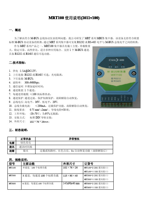
MRT100使用说明(2011v100)一.概述为了解决符合M-BUS总线协议仪表组网问题,我公司研发了MRT系列MBUS集中器。
该设备支持符合欧盟标准M-BUS协议设备的转换。
通过MRT系列集中器可实现RS232或RS-485电平与M-BUS总线电平之间的转换。
作为MRT系列产品之一,MRT100集中器具有施工方便,带载数量大,稳定可靠,高性价比,适合多种应用场合。
支持1个M-BUS通道,具备RS232或RS485通信可选功能。
二.技术指标:1.供电:1.5A@DC12V;2.上行连接:RS232或RS485可选;光电隔离;3.下行连接:M-BUS;4.波特率:300~9600bps;5.通信延时:不增加延时时间;6.通道数量:1个通道;7.每通道带载数:≤100块标准热表;8.通道保护:通道过流、保护短路保护,故障解除自动恢复;9.总线电压:高电平:36V,低电平:20V;10.总线负载电流:≤200mA,过载保护功能,故障解除自动恢复;11.接线要求:0.75mm²~2mm²;导线电阻<50欧;12.工作环境:-20~70℃;5~95%无凝露;13.安装方式:标准DIN导轨安装;14.外形尺寸:102×76×26mm。
三、状态说明:正常状态异常情况电源绿色常亮通讯通讯时闪烁故障熄灭过载或短路时,红色点亮,5s自动恢复功能(故障解除后)四、规格说明:型号主要功能外形尺寸订货号MRT100单通道,100个标准负载102×76×26MRT100-2(232通讯接口)MRT100-4(485通讯接口)MRT3003通道,每通道100个标准负载115×90×40MRT300-2(232通讯接口)MRT300-4(485通讯接口)MRT6006通道,每通道100个标准负载145x90x40mm MRT600-2(232通讯接口)MRT600-4(485通讯接口)。

M-BUS集中器说明书1 概述集中器带有M-BUS、RS232,RS485 接口分别与M-Bus 仪表和抄表主站或控制器连接。
与M-BUS 仪表的通讯,采用消费类仪表国际标准M-BUS(Meter-BUS,EN1434-3),按照树型总线连接。
2 型号介绍集中器型号包括HS1101,HS1101B,HS1102A 和HS1106B 四种种型号。
2.1 HS1101A 型为单路无通讯协议转换型,该型号提供M-BUS 接口和RS232 或RS485 接口,只支持数据透传,直接通过RS232 或RS485接口发送读表指令。
最大连接仪表数量为60 块。
2.2 HS1101B 型为单路支持标准MODBUS 协议型,用户可发送标准MODBUS 协议指令读取仪表数据。
最大连接仪表数量为60 块。
2.3 HS1102A 型为多路(最大6 路)无通讯协议转换型,提供可选的1至6路,最大连接仪表数量为360 块。
2.4 HS1102B 型为多路(最大6 路)支持标准MODBUS 协议型,用户可发送标准MODBUS 协议指令读取仪表数据。
最大支持仪表数量360 块。
3 性能指标3.1 工作电压:12V 1A DC。
3.2 通讯接口:RS232/RS485 接口,M-BUS 接口。
3.3 该集中器提供单路或多路M-BUS 接口,单个集中器最多支持6 路,每路可连接60 块仪表。
3.4 指示灯包括电源指示,收发状态指示,过载报警指示。
3.5 工作环境:温度:-30℃---80℃湿度:90%,无结晶。
4 功能特点4.1 集中器带有M-BUS、RS232,RS485接口分别与M-Bus仪表和抄表主站或控制器连接4.2 单个集中器最多可连接M-BUS仪表360台(六路通道,每路接表60台)4.3 热量表与集中器的通讯连接,采用消费类仪表国际标准M-BUS(Meter-BUS,EN1434-3),按照树型总线连接4.4 采用普通的两芯电缆连接,同时完成数据通讯和提供通讯电源的功能,最大传输距离可达1000 米。
ZNE-100T以太网转串口模块的应用 (2)1.ZNE-100T模块功能简介 (2)2.ZNE-100T模块硬件电路说明 (3)3.硬件连接使用说明 (7)4.软件配置使用说明 (8)(1)安装配置软件 (10)(2)利用配置软件进行配置 (12)5.网页配置说明 (20)6.ZNE-100T的应用领域 (27)7.ZNE-100T与LPC213X的硬件连接 (29)8.实验过程及现象 (29)ZNE-100T以太网转串口模块的应用1. ZNE-100T 模块功能简介ZNE-100T是周立功公司开发的一款嵌入式网络模块,它内部集成了TCP/IP协议栈,用户利用它可以轻松完成嵌入式设备的网络功能,节省人力物力和开发时间,使产品更快的投入市场,增强竞争力。
(1)功能特点z Serial (TTL) to 10M Ethernet,Serial最大波特率为115200 bps;z可利用Web browser和Windows utility 轻松进行设定;z TCP Server,TCP Client, UDP, Real COM ,Group组播等作业模式;z支持动态(DHCP)或静态获取IP地址;z提供5个可控制I/O口;z尺寸小(44×31.5mm)。
(2)产品特性z32位ARM7 CPU;z16KB RAM;z128KB FLASH;z10M以太网接口(使用排针方式引出);z 1.5KV 电磁隔离;z串口TTL电平方式,波特率300~115200 bps;z串口任意校验;z串口数据位5,6,7,8可设定;z串口停止位1,2位可设定;z支持TCP/IP协议包括:ETHERNET、ARP、IP、ICMP、IGMP、UDP、TCP、HTTP、DHCP;z工作方式可选择为TCP Server, TCP Client, UDP, Real COM driver,Group Mode,组播地址、工作端口、目标IP和端口均可设定,支持Pair Connection 对连方式工作;z提供5个可控制I/O,可通过网页控制或TCP控制,控制端口任意设定;z提供Real COM driver模式下的管理软件,可动态修改串口参数,真正实现虚拟串口;z提供Group Mode组播模式下的数据分组广播,实现多机通讯,轻松实现RS485网络到以太网的升级;z提供串口起始字节和结束字节分包功能;z可使用配置工具ZnetCom Utility for Windows98/me/NT/2000/XP进行配置;z另外提供通用配置函数库,方便用户使用VC、VB、Delphi和C++ Builder开发应用程序z可使用网页浏览器进行配置;z输入电压 5V DC;z功耗低最大工作电流 38 mA;z工作温度0~65ºC;z保存温度-25~85ºC。
发布日期2013-05-07版本 1.60页数共6页文件类型受控文件M-BUS网络预付费水表电子模块用户手册产品名称M-BUS网络预付费水表电子模块应用范围水表数据采集与控制产品型号CJ-MA602Y-V16软件版本号V2.75文件编号产品版本版本发布日期更改内容发布者1.602013-10-16增加报警点关阀后过10秒自动开阀Yu目录1.概述1.1简介 (1)1.2功能介绍 (1)2.技术指标2.1技术参数 (2)3.安装指南 (4)4.注意事项 (4)5.典型应用 (5)1.概述1.1简介水表是与人民生活有密切关系的户用仪表,这些表都是贸易结算型的计量仪表。
网络预付费水表电子模块是和基表(电子发讯表)配合使用的。
电子模块在电路设计中使用美国德州仪器公司的微功耗单片机作为微处理器。
它能完成下列规定功能:接受从水表发出的脉冲信号进行计数、运算处理及实时控制,按确定的通信协议与上位机进行双向传输,并对水表进行有效的管理。
14工作模式预付费模式可将预付费模式放在表头部分或者放在上位机部分;放在上位机部分报警点和关阀点功能不起作用;默认不激活磁干扰关阀模式激活磁干扰关阀模式,检测到磁干扰后关阀不激活时只报警,默认不激活与预付费模式无关。
15读阶梯价将表内正运行的阶梯价读出16读报警点关阀点将表内正运行的报警点,关阀点,定量点,工作模式等参数读出2.技术指标4.安装指南1.参考图片2.管脚说明管脚号码名称说明1电池负接电池负极2电池正接电池正极3电机驱动端驱动电机正转(开阀)4电机驱动端驱动电机反转(关阀)5地接到位开关公共端6开到位接到位开关开到位7关到位接到位开关关到位8计量信号公共端(地)接干簧管公共端9计量信号信号端接干簧管10计量信号信号端接干簧管11计量信号供电端不接12计量信号供电端不接13M-BUS通信接口14M-BUS通信接口。
迅饶Mbus集中器使用说明
一、Mbus 介绍
M-Bus 远程抄表系统(symphonic mbus)是欧洲标准的2 线的二总线,主要用于消耗测量仪器,诸如热表和水表,流量计系列。
Mbus 总线是欧洲标准,与普通485 总线主要区别在于:
1,Mbus 两线没有正负之分(无极性),而485 总线是有正负极性之分;
2,Mbus 总线工作是有30~36V 工作电压,用于仪表传输数据;485 总线一般工作电压是3.8V 左右;
3,Mbus 可以完全支持星型连接方式总线,485 总线常规都是需要手拉手串联方式;
二、Mbus 集中器工作原理
迅饶Mbus 集中器通过Mbus 接口连接到仪表Mbus 总线,然后转换为
RS485/RS232 电平方式,这样可以让PC 上位机或者串口设备访问终端仪表。
三、接线图
Mbus-RS485 转换模块,提供Mbus 总线至RS485 总线转换服务;
●供电:DC12V~24V
● Mbus 接线:5 组Mbus 总线Mbus+,Mbus-(每组不超过32 台设备)
●通信口:隔离RS485 通信的A+B-信号线。
SMS100 SMS (Text) ModuleUser’s ManualRevision 1.0Copyright © 2013 Maretron, LLP All Rights ReservedMaretron, LLP9014 N. 23rd Ave #10Phoenix, AZ 85021Maretron Manual Part #: M003040SMS100 User's ManualRevision HistoryRevision Description Release1.0 InitialTable of Contents1 General (1)1.1 Introduction (1)1.2 Firmware Revision (1)1.3 Features (1)1.4 Quick Install (1)1.5 Theory of Operation (2)1.5.1 SIM Card (2)2 Installation (2)2.1 Unpacking the Box (2)2.2 Choosing a Mounting Location (2)2.3 SIM Card (2)2.3.1 Purchasing a SIM Card (2)2.3.2 Installing the SIM Card (3)2.4 Mounting the SMS100 (4)2.5 Connecting the SMS100 (4)2.5.1 NMEA 2000® Connection (4)2.5.2 Cellular Antenna Connection (5)3 Configuring the SMS100 (5)3.1 Advanced Configuration (5)3.1.1 Device Instance (5)3.1.2 Installation Description (5)3.1.3 Restore Factory Defaults (5)3.2 Label (6)4 Usage (6)4.1 Transmitting Messages (6)4.2 Receiving Messages (6)4.3 Monitoring the SMS100 (6)5 Maintenance (6)6 Troubleshooting (7)7 Technical Specifications (7)8 Regulatory Compliance (9)8.1 FCC (9)9 Technical Support (9)10 Installation Template (10)11 Maretron (2 Year) Limited Warranty (11)SMS100 User's ManualTable of FiguresFigure 1 – Mounting the SMS100 (4)Figure 2 – NMEA 2000® Connector Face Views (5)Figure 3 – Troubleshooting Guide (7)Figure 4 – Mounting Template (10)1 General1.1 IntroductionCongratulations on your purchase of the Maretron SMS (Text) Module (SMS100). Maretron has designed and built your SMS module to the highest standards for years of reliable, dependable, and accurate service.Maretron’s SMS100 SMS (Text_ Module is a device which can programmatically send SMS (Short Message Service, or text message) alerts over the GSM/UMTS network to multiple mobile telephone users. Maretron’s SMS100 SMS Module works in concert with Maretron’sN2KView® Vessel Monitoring System and Maretron’s DSM150 and DSM250 displays. Upon detection of an alert condition, N2KView (with the optional Alerts module), a DSM150 display, or a DSM250 display can instruct the SMS100 to connect to the mobile network and transmit a user-selected alert message to user-programmed telephone numbers, alerting you quickly to conditions onboard your vessel that require attention anywhere you have cellular network coverage. You may also send a text message from your mobile phone to the SMS100, which will reply with basic ship’s status.The SMS100 has an NMEA 2000® port for communication with the attached NMEA 2000®network and an SMA antenna connector for connecting the included mobile antenna.The Maretron SMS100 is designed to operate within the harsh demands of the marine environment. However, no piece of marine electronic equipment can function properly unless installed, calibrated, and maintained in the correct manner. Please read carefully and follow these instructions for installation, calibration, and usage of the Maretron SMS100 in order to ensure optimal performance.1.2 Firmware RevisionThis manual corresponds to SMS100 firmware revision 1.0.0.1.3 FeaturesThe Maretron SMS100 has the following features:• NMEA 2000® interface•Can be used along with Maretron’s N2KView software running on the following platforms:o DSM800 displayo TSM800 displayo TSM1330 displayo Windows PC running N2KView softwareo Mac OS/X PC running N2KView software•Can be used along with Maretron’s DSM150 or DSM250 displays1.4 Quick InstallInstalling the Maretron SMS100 involves the following steps. Please refer to the individual sections for additional details.SMS100 User's Manual1. Unpacking the Box (Section2.1)2. Choosing a Mounting Location (Section 2.2)3. Installing the SIM Card (Section 2.3)4. Mounting the SMS100 (Section 2.4)5. Connecting the SMS100 (Section 2.5)6. Configuring the SMS100 (Section 3)1.5 Theory of OperationThe SMS100 accepts commands over its NMEA 2000® network connection which have generated by N2KView software with the optional alerts module or from DSM150 or DSM250 displays and transmits these text messages over the cellular network to user selected telephone numbers.1.5.1 SIM CardIn order to use the SMS100, you must install a SIM card with an active SMS plan that is capable of connecting to a mobile network in the area in which you are using the SMS100.2 Installation2.1 Unpacking the BoxWhen unpacking the box containing the Maretron SMS100, you should find the following items: • 1 – SMS100 SMS (Text) Module• 1 – Parts Bag containing 4 Stainless Steel Mounting Screws• 1 – SMS100 User’s Manual• 1 – Warranty Registration Card• 1 – TG.10.0113 Cellular AntennaIf any of these items are missing or damaged, please contact Maretron.2.2 Choosing a Mounting LocationPlease consider the following when choosing a mounting location.1. The SMS100 is waterproof, so it can be mounted in a damp or dry location.2. The orientation of the SMS100 is not important, so the SMS100 can be mounted on ahorizontal deck, or a vertical bulkhead.3. The SMS100 is temperature-rated to 55°C (130°F), so it should be mounted away fromengines or engine rooms where the operating temperature exceeds the specified limit.2.3 SIM Card2.3.1 Purchasing a SIM CardIn the United States, the SMS100 is certified for the AT&T mobile network.AT&T Prepaid (goPhone) SIM cards may be purchased at an AT&T retail location or from a large number of online retailers (search “gophone SIM card”).The SIM card will come with instructions for activating the card online and adding funds to the card. The SIM card must be activated before you can transmit messages with the SMS100. When this manual was written, there were two prepaid plan options:•The $25/month plan with unlimited text messaging•The 10 cent per minute plan (no monthly fee, but $0.20 per message sent or received). Please check Maretron’s website for the latest information.2.3.2 Installing the SIM CardIn order to use the SMS100, the SIM card must be installed into the SMS100. To install the SIM card, please perform the following steps:1) Remove the four screws from the bottom of the SMS100 enclosure.2) Separate the top and bottom of the SMS100 enclosure.3) Slide the lid of the SIM card socket to the “OPEN” position and flip up.4) Slide the SIM card into the lid of the SIM card socket so that the gold contacts arevisible and so that the corner of the SIM card that is cut off is at the top of the SIM card socket lid.5) Close the SIM card socket lid and slide it to the “LOCK” position. Be careful not to forcethe lid into position. It should close easily. If it does not, check the orientation andalignment of the SIM card.6) Reassemble the top and bottom parts of the SIM100 enclosure with the four screwsremoved earlier, ensuring that the gasket is seated properly.The SIM card is now installed.SMS100 User's Manual2.4 Mounting the SMS100The SMS100 may be mounted to a horizontal or a vertical surface; the only requirement is that the antenna be oriented vertically after the unit is mounted.The SMS100 may be mounted using the two keyhole screw holes on each end.To mount, attach the SMS100 securely to the vessel using the included stainless steel mounting screws or other fasteners as shown in Figure 1. Using the mounting template in Section 10, drill two holes for the included mounting screws and install the screws, leaving the head of the screws protruding above the mounting surface. Place the SMS100 over the mounting screws and slide so that the heads of the mounting screws are over the narrow portions of the keyhole slots, then tighten the mounting screws until snug.Figure 1 – Mounting the SMS1002.5 Connecting the SMS1002.5.1 NMEA 2000® ConnectionThe NMEA 2000® connector can be found on the side of the enclosure. The NMEA 2000®connector is a round five pin male connector (see Figure 2). You connect the SMS100 to an NMEA 2000® network using a Maretron NMEA 2000® cable (or an NMEA 2000® compatible cable) by connecting the female end of the cable to the SMS100 (note the key on the male connector and keyway on the female connector). Be sure the cable is connected securely and that the collar on the cable connector is tightened firmly. Connect the other end of the cable (male) to the NMEA 2000® network in the same manner. The SMS100 is designed such that you can plug or unplug it from an NMEA 2000® network while the power to the network is connected or disconnected. Please follow recommended practices for installing NMEA 2000®network products.Figure 2 – NMEA 2000® Connector Face Views2.5.2 Cellular Antenna ConnectionThe SMS100 has one external SMA cellular antenna connector. This connector is intended for use only with the included TG.10.0113 cellular antenna. Screw the antenna onto the SMA connector and tighten until snug. Rotate the antenna so that it is a vertical orientation for best signal reception.3 Configuring the SMS100The SMS100 has several configurable parameters, which are shown below including the default values. If you are not using the default values, then you will need to refer to the corresponding section for configuring the SMS100 appropriately. You may configure the SMS100 using a Maretron DSM150 or DSM250 display or Maretron N2KAnalyzer® software. 3.1 Advanced Configuration3.1.1 Device InstanceProgram this parameter to the desired instance number for this device. You can program this parameter to any value between 0 and 252. The default device instance is 03.1.2 Installation DescriptionThis entry allows you to modify the NMEA 2000® installation description text strings. You can enter any information you like here, such as the date the unit was installed, or the location in which it was installed, for later reference. Tools such as Maretron N2KAnalyzer® allow you to view these values later. The default installation description is blank text.3.1.3 Restore Factory DefaultsThis option restores all settings on the SMS100 device to their factory default states.SMS100 User's Manual3.2 LabelProgram this parameter with a text string which identifies this device. Maretron display products will display this label text when you are selecting data to display. The default device label is blank.4 Usage4.1 Transmitting MessagesThe SMS100 may be used to transmit SMS text messages to user-selected telephone numbers on the occurrence of an alert generated by N2KView software (with the optional Alerts license) or the DSM150 or DSM250 displays. Please refer to the N2KView User’s Manual, DSM150 User’s Manual, or DSM250 User’s Manual, as appropriate, for details.4.2 Receiving MessagesYou may send a message to the SMS100 in order to receive a predefined message showing the current status of various parameters on the vessel.Send a SMS message containing the single word “STATUS” to the telephone number of the SMS100.The SMS100 will respond with a text message containing the following information:1) Position2) Bilge Water Detector Status3) Battery Voltage4) AC Voltage5) Apparent Wind Speed6) Outdoor Temperature7) Indoor Temperature4.3 Monitoring the SMS100The state of the SMS100’s connection to the cellular network may be observed using N2KView software or the DSM150 or DSM250 displays. Please refer to the N2KView User’s Manual, DSM150 User’s Manual, or DSM250 User’s Manual, as appropriate, for details. From these devices and software, you can observe the following information:1) Cellular Carrier2) Telephone number of the SMS1003) Signal Strength5 MaintenanceRegular maintenance is not required; however, an occasional inspection will ensure continued proper operation of the Maretron SMS100. Perform the following tasks periodically:•Clean the unit with a soft cloth. Do not use chemical cleaners as they may remove paint or markings or may corrode the SMS100 enclosure or seals. Do not use any cleaners containing acetone, as they will deteriorate the plastic enclosure.•Ensure that the unit is mounted securely and cannot be moved relative to the mounting surface. If the unit is loose, tighten the mounting screws.•Check the security of all cable connections and tighten if necessary.6 TroubleshootingIf you notice unexpected operation of the Maretron SMS100, follow the troubleshooting procedures in this section to remedy simple problems.Symptom Troubleshooting ProcedureText Messages not Transmitted •Check the connection to the NMEA 2000® and connector and tighten if necessary•Ensure that power is supplied to the connected NMEA 2000®network segment• Use N2KView®, a DSM150, or DSM250 to verify Cellular Provider, signal strength, and active SIM card status•Check that the proper cellular telephone number has been programmed into N2KView®, the DSM150, or DSM250No Cellular Provider Indicated •Check that the antenna is connected properly to the antenna connector on the SMS100•Check to see if you are within the coverage area of the cellular operator whose SIM card is installed in the SMS100•Check that the SIM card has an active SMS planSIM Card Not Ready or Present •Check that the SIM card is properly installed in the SMS100 •Check that the SIM card has an active SMS planFigure 3 – Troubleshooting GuideIf these steps do not solve your problem, please contact Maretron Technical Support (refer to Section 8 for contact information).7 Technical SpecificationsSpecificationsParameter Value CommentNMEA 2000® Connector DeviceNet Micro-C Industry Standard WaterproofNMEA 2000® Isolation Opto-IsolatedAntenna Connector SMA For use only with supplied cellular antennaCellular Technologies 2G GSM/GPRS/EDGE3G UMTS/HSDPA/HSUPASupported Bands 800/850/900/1700/1900/2100 MHzSMS100 User's ManualCertificationsParameter CommentNMEA 2000® Standard Level AMaritime Navigation and Radiocommunication Equipment & Systems IEC 61162-3Maritime Navigation and Radiocommunication Equipment & Systems IEC 60945FCC and R&TTE/CE Mark Electromagnetic CompatibilityPTCRB Certified AT&T Network ReadyNMEA 2000® Parameter Group Numbers (PGNs)Description PGN # PGN Name Default RateResponse to Requested PGNs 126464 PGN List (Transmit and Receive) N/A 126996 Product Information N/A 126998 Configuration Information N/AProtocol PGNs 059392 ISO Acknowledge N/A059904 ISO Request N/A060416 ISO Transport Protocol, Connection Management N/A060160 ISO Transport Protocol, Data Transfer N/A060928 ISO Address Claim N/A065240 ISO Address Command N/A126208 NMEA Request/Command/Acknowledge N/A Periodic PGNs 130834 SMS Status (Maretron Proprietary) 10 seconds130835 SMS Text Message (Maretron Proprietary) On Receipt ElectricalParameter Value CommentOperating Voltage 9 to 32 Volts DC VoltagePower Consumption <150mA Average Current DrainLoad Equivalence Number (LEN) 3 NMEA 2000® Spec. (1LEN = 50 mA) Reverse Battery Protection Yes IndefinitelyLoad Dump Protection Yes Energy Rated per SAE J1113 MechanicalParameter Value CommentSize 6.871” x 3.571” x 2.045”(152mm x 91mm x 52 mm) Including Flanges for Mounting Not Including Cellular AntennaWeight 10.6 oz. (301 g)EnvironmentalParameter ValueIEC 60945 Classification ExposedDegree of Protection IP65Operating Temperature -25°C to 55°CStorage Temperature -40°C to 85°CRelative Humidity 93%RH @40° per IEC60945-8.2Vibration 2-13.2Hz @ ±1mm, 13.2-100Hz @ 7m/s2 per IEC 60945-8.7Rain and Spray 12.5mm Nozzle @ 100liters/min from 3m for 30min per IEC 60945-8.8 Solar Radiation Ultraviolet B, A, Visible, and Infrared per IEC 60945-8.10 Corrosion (Salt Mist) 4 times 7days @ 40°C, 95%RH after 2 hour Salt Spray Per IEC 60945-8.12 Electromagnetic Immunity Conducted, Radiated, Fast Transient, Supply, and ESD per IEC 60945-10 Safety Precautions Dangerous Voltage, Electromagnetic Radio Frequency per IEC 60945-128 Regulatory Compliance8.1 FCCThis device complies with part 15 of the FCC Rules. Operation is subject to the following two conditions: (1) This device may not cause harmful interference, and (2) this device must accept any interference received, including interference that may cause undesired operation. CONTAINS FCC ID: XPYLISAU2009 Technical SupportIf you require technical support for Maretron products, you can reach us in any of the following ways:1-866-550-9100Telephone:1-602-861-1777Fax:********************E-mail:World Wide Web: Mail:LLPMaretron,Attn: Technical Support9014 N. 23rd Ave Suite 10Phoenix, AZ 85021 USASMS100 User's Manual10 I nstallation TemplatePlease check the dimensions before using the following diagram as a template for drilling theFigure 4 – Mounting Template11 M aretron (2 Year) Limited WarrantyMaretron warrants the SMS100 to be free from defects in materials and workmanship for two (2) years from the date of original purchase. If within the applicable period any such products shall be proved to Maretron’s satisfaction to fail to meet the above limited warranty, such products shall be repaired or replaced at Maretron’s option. Purchaser's exclusive remedy and Maretron’s sole obligation hereunder, provided product is returned pursuant to the return requirements below, shall be limited to the repair or replacement, at Maretron’s option, of any product not meeting the above limited warranty and which is returned to Maretron; or if Maretron is unable to deliver a replacement that is free from defects in materials or workmanship, Purchaser’s payment for such product will be refunded. Maretron assumes no liability whatsoever for expenses of removing any defective product or part or for installing the repaired product or part or a replacement therefore or for any loss or damage to equipment in connection with which Maretron’s products or parts shall be used. With respect to products not manufactured by Maretron, Maretron’s warranty obligation shall in all respects conform to and be limited to the warranty actually extended to Maretron by its supplier. The foregoing warranties shall not apply with respect to products subjected to negligence, misuse, misapplication, accident, damages by circumstances beyond Maretron’s control, to improper installation, operation, maintenance, or storage, or to other than normal use or service.THE FOREGOING WARRANTIES ARE EXPRESSLY IN LIEU OF AND EXCLUDES ALL OTHER EXPRESS OR IMPLIED WARRANTIES, INCLUDING BUT NOT LIMITED TO THE IMPLIED WARRANTIES OF MERCHANTABILITY AND OF FITNESS FOR A PARTICULAR PURPOSE.Statements made by any person, including representatives of Maretron, which are inconsistent or in conflict with the terms of this Limited Warranty, shall not be binding upon Maretron unless reduced to writing and approved by an officer of Maretron.IN NO CASE WILL MARETRON BE LIABLE FOR INCIDENTAL OR CONSEQUENTIAL DAMAGES, DAMAGES FOR LOSS OF USE, LOSS OF ANTICIPATED PROFITS OR SAVINGS, OR ANY OTHER LOSS INCURRED BECAUSE OF INTERRUPTION OF SERVICE. IN NO EVENT SHALL MARETRON’S AGGREGATE LIABILITY EXCEED THE PURCHASE PRICE OF THE PRODUCT(S) INVOLVED. MARETRON SHALL NOT BE SUBJECT TO ANY OTHER OBLIGATIONS OR LIABILITIES, WHETHER ARISING OUT OF BREACH OF CONTRACT OR WARRANTY, TORT (INCLUDING NEGLIGENCE), OR OTHER THEORIES OF LAW WITH RESPECT TO PRODUCTS SOLD OR SERVICES RENDERED BY MARETRON, OR ANY UNDERTAKINGS, ACTS OR OMISSIONS RELATING THERETO.Maretron does not warrant that the functions contained in any software programs or products will meet purchaser’s requirements or that the operation of the software programs or products will be uninterrupted or error free. Purchaser assumes responsibility for the selection of the software programs or products to achieve the intended results, and for the installation, use and results obtained from said programs or products. No specifications, samples, descriptions, or illustrations provided Maretron to Purchaser, whether directly, in trade literature, brochures or other documentation shall be construed as warranties of any kind, and any failure to conform with such specifications, samples, descriptions, or illustrations shall not constitute any breach of Maretron’s limited warranty.Warranty Return Procedure:To apply for warranty claims, contact Maretron or one of its dealers to describe the problem and determine the appropriate course of action. If a return is necessary, place the product in its original packaging together with proof of purchase and send to an Authorized Maretron Service Location. You are responsible for all shipping and insurance charges. Maretron will return the replaced or repaired product with all shipping and handling prepaid except for requests requiring expedited shipping (i.e. overnight shipments). Failure to follow this warranty return procedure could result in the product’s warranty becoming null and void.Maretron reserves the right to modify or replace, at its sole discretion, without prior notification, the warranty listed above. To obtain a copy of the then current warranty policy, please go to the following web page:/company/warranty.php。
TH-MR100使用手册
TH-MR100概述
为了便于连接符合EN1434、EN13757等标准的总线设备,我公司研发了TH-MR100 设备,该设备支持符合欧盟标准的M-BUS 协议设备的转换。
通过TH-MR100,M-BUS 电平转换为RS232电平,PC 机或其它设备可以通过串口直接访问M-BUS设备。
TH-MR100实物图如下:
图1:TH-MR100实物图
⏹采用冗余设计方式,稳定工作范围宽
⏹输出短路、过载保护,输入防反接设计,更安全可靠⏹供电:24VDC
⏹外壳:金属
⏹工作温度:-10℃~70℃
⏹存储温度:-40℃~125℃
⏹工作湿度:5%~95%,无凝露
⏹通信速率:300bps~9600bps,流控自适应
⏹负载能力:5
⏹指示灯:电源、过载短路、数据通信
⏹外形尺寸(mm):105*53*30
⏹电磁兼容:轻工业级标准
⏹串口方式:RS232
⏹支持所有进口热表解码;提供国产表解码支持
⏹上位机软件免费提供
图2 TH-MR100外观图
图 3 TH-MR100模块简单控制接线图
RS232为DB9母头,可与PC直连通信,其线序为:
2:TXD(接PC或控制器的RXD)
3:RXD(接PC或控制器的TXD)
5:GND(接PC或控制器的GND)
使用情况:
1、刚上电时,Power灯亮,如不亮请检查电源是否正常,COM灯不亮,如常亮
则说明M+与M-之间短路。
2、在通讯过程中,COM灯不断闪烁,说明上位机在读设备的数据,读数完毕后,
COM灯恢复熄灭。
3、如果模块过载,COM灯亮,此时需要断电一段时间,减小负载后,再给模块
重新上电才能正常通讯。
4、M-BUS 的传输距离可达1km-2km,与挂接仪表的波特率有关,波特率越低
传输距离越远,如果要传输2km,必须把波特率设置成300bps。
M-BUS 标准要求,传输线阻必须小于90 欧姆,否则对模块的负载能力有影响。
5、信号M+和M-不能短路,短路后需要断电、重新上电后,模块才能恢复正
常工作状态。
6、TH-MR100能够承受长时间的M+/M-之间的短路,只要将短路故障排除,数
秒之内模块即可恢复正常工作。
M-BUS测试软件使用说明
【第一步】打开M-bus热表数据测试软件,在“串口选择”栏目中,正确选择连接TH-MR100的串口号和串口通信波特率(默认2400),而后点击“打开串口”。
如下图所示:
图5 设置操作串口
【第二步】在“仪表设置”栏目中,选择和输入M-BUS总线上设备的地址。
选择“自动”,程序将主动尝试使用万能读表指令进行通信。
也可填入实际的热表地址(16进制)。
之后点击“开始读数”按钮。
如下图所示:
图6 设置仪表/开始读数
【第三步】1s之后,返回结果如下图。
数据自动完整解码,我们可提供遵循EN13757-3协议的热表(进口表)的解码DLL文件和编程参考!
图7 返回数据和数据解码
附录:
一般M-BUS 设备的串口参数设置为波特率2400,8 为数据位,1 为停止位,偶校验,十六进制码制。
1、进口表读表命令:105BFE5916,其中FE 是万能地址,回复的是一串数据,字
节数可能不同。
2、国产表指令不一。
3、M-BUS总线的电平特性如下:
发送:传号电压:24V~36V(CJ-T188-2004:20.8V~42V)
空号电压:传号电压-12V(CJ-T188-2004:传号电压-10V)
接收:传号电流:≤1.5mA
空号电流:11~20mA
更多信息请访问。